JP2007239801A - Angular contact ball bearing with seal - Google Patents
Angular contact ball bearing with seal Download PDFInfo
- Publication number
- JP2007239801A JP2007239801A JP2006060029A JP2006060029A JP2007239801A JP 2007239801 A JP2007239801 A JP 2007239801A JP 2006060029 A JP2006060029 A JP 2006060029A JP 2006060029 A JP2006060029 A JP 2006060029A JP 2007239801 A JP2007239801 A JP 2007239801A
- Authority
- JP
- Japan
- Prior art keywords
- bearing
- outer ring
- seal
- diameter
- grease
- Prior art date
- Legal status (The legal status is an assumption and is not a legal conclusion. Google has not performed a legal analysis and makes no representation as to the accuracy of the status listed.)
- Pending
Links
Images

Landscapes
- Rolling Contact Bearings (AREA)
Abstract
Description
本発明は、シール付きアンギュラ玉軸受に関し、特に、工作機械の主軸を回転支持するために使用されるシール付きアンギュラ玉軸受に関するものである。 The present invention relates to a sealed angular contact ball bearing, and more particularly to a sealed angular contact ball bearing used for rotationally supporting a spindle of a machine tool.
近年、工作機械の主軸を回転支持するアンギュラ玉軸受では、グリースの長寿命化と主軸装置への組み付け性等の観点から、グリースが予め封入され、シールにより密封されているシール付きアンギュラ玉軸受のニーズが高まっている(例えば、特許文献1参照)。一般に、アンギュラ玉軸受では、国際規格(ISO15)の主要寸法によって、軸受内径、軸受外径、軸受幅等、標準的な軸受寸法が規定されており、主軸やハウジングの寸法によって規格内の軸受が採用される。JIS規格(JISB1522)もこれと整合しており、アンギュラ玉軸受は、寸法系列が19,10,02及び03である一般に用いる軸受の寸法範囲から定められている。上記のシール付きアンギュラ玉軸受でも、この標準的な軸受寸法を有するものが使用されており、シール部材によって囲まれる内輪と外輪との間の軸受空間に、例えば、空間容積の15〜30%程度のグリースが封入されている。
ところで、従来のシール付きアンギュラ玉軸受では、グリースを多く封入することでグリース耐久性を向上することができるが、空間容積の30%程度のグリースを軸受空間内に封入する場合、グリースの落ちつきが悪く、グリースの慣らし運転をする際に多くの時間がかかる。 By the way, in a conventional angular contact ball bearing with a seal, it is possible to improve the grease durability by enclosing a large amount of grease. However, when grease of about 30% of the space volume is encapsulated in the bearing space, the grease is not settled. Unfortunately, it takes a lot of time to run-in the grease.
一方、従来のシール付きアンギュラ玉軸受では、シールと保持器の干渉を避けるため、或いは、グリースを封入するための空間容積を大きくとるため、保持器の幅を小さくして使用されることがあり、保持器の強度が不十分となる可能性がある。 On the other hand, conventional angular contact ball bearings with seals may be used with a smaller cage width in order to avoid interference between the seal and the cage, or to increase the space volume for enclosing grease. The strength of the cage may be insufficient.
本発明は、上記事情を鑑みてなされたものであり、その目的は、グリースの慣らし運転時間を長期化することなく、グリース封入量を多くすることができ、耐久性を向上できるシール付きアンギュラ玉軸受を提供する。 The present invention has been made in view of the above circumstances, and an object of the present invention is to provide an angular ball with a seal that can increase the amount of grease filled without increasing the operating time of the grease and can improve durability. Provide bearings.
本発明の上記目的は、下記構成によって達成される。
(1) 外周面に内輪軌道面を有する内輪と、内周面に外輪軌道面を有する外輪と、前記外輪軌道面と前記内輪軌道面との間に転動自在に配置された複数の玉と、該複数の玉を円周方向に所定の間隔で保持する保持器と、前記外輪の軸方向両端部に形成されたシール溝に嵌合されたシール部材と、を備えるシール付きアンギュラ玉軸受であって、
前記内輪の内径寸法をd、前記外輪の外径寸法をDとすると、前記軸受の軸方向断面寸法X、前記軸受の径方向断面寸法(D−d)/2、玉径Daとの関係は、
1.2≦(X/Da)/{(D−d)/2/Da}≦1.4
であることを特徴とするシール付きアンギュラ玉軸受。
The above object of the present invention is achieved by the following configurations.
(1) An inner ring having an inner ring raceway surface on an outer peripheral surface, an outer ring having an outer ring raceway surface on an inner peripheral surface, and a plurality of balls arranged in a freely rollable manner between the outer ring raceway surface and the inner ring raceway surface; A sealed angular contact ball bearing comprising: a cage that holds the plurality of balls in the circumferential direction at predetermined intervals; and a seal member that is fitted in seal grooves formed at both axial ends of the outer ring. There,
When the inner diameter of the inner ring is d and the outer diameter of the outer ring is D, the relationship between the axial sectional dimension X of the bearing, the radial sectional dimension (Dd) / 2 of the bearing, and the ball diameter Da is ,
1.2 ≦ (X / Da) / {(D−d) / 2 / Da} ≦ 1.4
A sealed angular contact ball bearing characterized by being
本発明のシール付きアンギュラ玉軸受によれば、軸受の軸方向断面寸法X、軸受の径方向断面寸法(D−d)/2、玉径Daとの関係を、1.2≦(X/Da)/{(D−d)/2/Da}とし、アンギュラ玉軸受における標準的な軸受幅の寸法を変更し、軸受の径方向断面寸法に対し軸方向断面寸法を大きく設定している。これにより、グリースを封入するための空間容積を従来よりも広くすることができ、空間容積に対するグリース封入量の割合を同等にしても、グリース封入量の絶対量を多くすることができる。このグリース封入量のアップにより、グリース寿命の長期化を図ることができる。また、グリース封入量が多くなるものの、空間容積も広がるので、慣らし時間の長期化を避けることができる。また、(X/Da)/{(D−d)/2/Da}≦1.4とすることで、グリースを無駄に増加することがなく、経済性のよいものとなる。 According to the sealed angular contact ball bearing of the present invention, the relationship between the axial sectional dimension X of the bearing, the radial sectional dimension (Dd) / 2 of the bearing, and the ball diameter Da is 1.2 ≦ (X / Da ) / {(D−d) / 2 / Da}, the standard bearing width dimension of the angular ball bearing is changed, and the axial sectional dimension is set larger than the radial sectional dimension of the bearing. As a result, the space volume for enclosing the grease can be made wider than before, and the absolute amount of the grease enclosure amount can be increased even if the ratio of the grease enclosure amount to the space volume is equal. By increasing the amount of grease, the grease life can be extended. Further, although the amount of grease filled increases, the space volume also increases, so that it is possible to avoid a prolonged break-in time. Further, by setting (X / Da) / {(D−d) / 2 / Da} ≦ 1.4, the grease is not increased unnecessarily, and the cost is improved.
また、内輪の内径寸法dと外輪の外径寸法Dは、ISO15の主要寸法において直径系列が9または0の関係を有する構成であってもよい。この場合、主軸やハウジング等は従来のまま使用可能であり、軸受幅を極端に幅広とするわけではないので、取り付けに当たっては、外輪間座や内輪間座等で軸受の位置関係を調整すれば足り、大きな設計変更が不要となる。また、軸受幅を広げることにより、標準の保持器の使用が可能になり、保持器の強度向上も図れ、玉案内保持器の採用も可能になる。 In addition, the inner diameter dimension d of the inner ring and the outer diameter dimension D of the outer ring may be configured such that the diameter series in the main dimension of ISO 15 has a relationship of 9 or 0. In this case, the main shaft, housing, etc. can be used as they are, and the bearing width does not become extremely wide.Therefore, when mounting, if the positional relationship of the bearing is adjusted with the outer ring spacer or inner ring spacer, etc. There is no need for major design changes. In addition, by expanding the bearing width, a standard cage can be used, the strength of the cage can be improved, and a ball guide cage can be adopted.
以下、本発明のシール付きアンギュラ玉軸受が組み込まれる主軸装置の一実施形態について図面を参照して説明する。 DESCRIPTION OF EMBODIMENTS Hereinafter, an embodiment of a spindle apparatus in which a sealed angular ball bearing of the present invention is incorporated will be described with reference to the drawings.
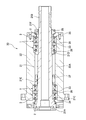
図1に示すように、工作機械に使用される主軸装置20では、主軸21は、その前後部が各々複列に並ぶシール付きアンギュラ玉軸受1を介してハウジング22に支持されている。各々のアンギュラ玉軸受1は、2列ずつが互いに背面を向けて配置されている(DBB組合せ)。
As shown in FIG. 1, in a
ハウジング22の内周面は円筒面とされ、中間部に小径の内鍔部22Aを有する。前方の2列のアンギュラ玉軸受1の外輪3は、これらの間に外輪間座23を配して、ハウジング22の内鍔部22Aと前蓋24との間に固定され、後方の2列のアンギュラ玉軸受1の外輪3も、これらの間に外輪間座23を配して、ハウジング22の内鍔部22Aと後蓋25との間に所定の隙間を持って配置される。
The inner peripheral surface of the housing 22 is a cylindrical surface, and has an
主軸21は、前部に工具ホルダ取付部21A、後部にプーリ取付部21Bが設けられており、前部及び中間部には後部に向けて徐々に縮径となるように段差21C,21Dが設けられている。前方の2列のアンギュラ玉軸受1の内輪2は、これらの間に内輪間座26を配して、主軸21の段差21Cと、主軸21に形成された雄ねじ部分21Eに螺合されるナット27によって挟みつけ状態で主軸21に固定され、後方の2列のアンギュラ玉軸受1の内輪2も、これらの間及びその前後に複数の内輪間座26を配して、主軸21の段差21Dと、主軸21に形成された雄ねじ部分21Fに螺合されるナット28によって挟みつけ状態で主軸21に固定される。
The
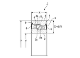
このシール付きアンギュラ玉軸受1は、外周面に内輪軌道面2aを有する内輪2と、内周面に外輪軌道面3aを有する外輪3と、外輪軌道面3aと内輪軌道面2aとの間に所定の接触角αを持って転動自在に配置された複数の玉4と、該複数の玉4によって案内されるとともに、複数の玉4を円周方向に所定の間隔で保持する保持器5と、外輪3の軸方向両端部に形成されたシール溝6、7に嵌合された非接触のシール部材8、9と、を備える。
This sealed angular
内輪2の内径寸法dと外輪3の外径寸法Dは、国際規格(ISO15)の主要寸法において直径系列が9または0の関係を満たすように設定されている。また、このシール付きアンギュラ玉軸受1の軸方向断面寸法(軸受幅)をX、軸受1の径方向断面寸法を(D−d)/2、玉径をDaとすると、表1及び表2に示されるように、これらの関係は、1.2≦(X/Da)/{(D−d)/2/Da}≦1.4、好ましくは、1.2≦(X/Da)/{(D−d)/2/Da}≦1.3となるように設定され、軸方向断面寸法Xは、従来の軸方向断面寸法Xよりも大きく幅広な軸受となる(図3及び図4参照)。特に、本実施形態では、軸受幅Xは、製造を簡潔に行えるように、国際規格(ISO15)の主要寸法において幅系列が2となるように設定されている。例えば、直径系列が9で、内輪2の内径寸法dが70mm、外輪3の外径寸法Dが100mmの場合、標準用及び超高速用での玉径Daはともに8.731mmのものが使用されており、長径系列が0で、内輪2の内径寸法dが70mm、外輪3の外径寸法Dが110mmの場合、標準用での玉径Daは11.906mmのものが使用され、超高速用での玉径Daは8.731mmのものがそれぞれ使用されている。
The inner diameter dimension d of the

ここで、(X/Da)/{(D−d)/2/Da}の値を1.2(下限値)より小さくすると、軸受空間を大きくとることができず、グリースの慣らし運転に時間がかかるため、十分な量のグリースを封入することができない。一方、1.4(上限値)より大きくすると、多量のグリースを封入する必要があり経済性が悪い。 Here, if the value of (X / Da) / {(D−d) / 2 / Da} is made smaller than 1.2 (lower limit value), the bearing space cannot be made large, and the grease break-in operation takes time. Therefore, a sufficient amount of grease cannot be sealed. On the other hand, if it is larger than 1.4 (upper limit value), it is necessary to enclose a large amount of grease, which is not economical.
例えば、直径系列が9または0の超高速用のシール付きアンギュラ玉軸受1は、表3及び表4に示すように、発明品の空間容積比を従来品のものに比べ1.25〜1.6倍とすることができる。これにより、慣らし運転の時間を同じ条件としても、グリース封入量を静的空間容積の30%に増加することができ、従来品に比べて2.5〜3倍の封入量となる。従って、グリース封入量のアップにより、グリース寿命の長期化を図ることができる。 For example, as shown in Tables 3 and 4, the ultra high speed sealed angular contact ball bearing 1 having a diameter series of 9 or 0 has a space volume ratio of 1.25 to 1. It can be 6 times. This makes it possible to increase the grease filling amount to 30% of the static space volume even when the running-in time is the same, which is 2.5 to 3 times that of the conventional product. Therefore, the grease life can be extended by increasing the amount of grease.
なお、本実施形態のシール付きアンギュラ玉軸受1では、保持器の外周面より径方向外方と、外輪の内周面との間に形成される空間容積は、従来品のものに比べ1.2〜1.6倍に設定されている。 In the sealed angular contact ball bearing 1 of the present embodiment, the spatial volume formed between the outer circumferential surface of the cage and the outer circumferential surface and the inner circumferential surface of the outer ring is 1. It is set to 2 to 1.6 times.
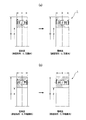
また、本発明のシール付きアンギュラ玉軸受1は、本実施形態のように玉案内方式の保持器であってもよく、或いは、外輪案内方式の保持器であってもよい。図3(a)は、直径系列が9で、且つ玉案内方式の従来品と発明品との対比を示し、図3(b)は、直径系列が9で、且つ外輪案内方式の従来品と発明品との対比を示す。図4(a)は、直径系列が0で、且つ玉案内方式の従来品と発明品との対比を示し、図4(b)は、直径系列が0で、且つ外輪案内方式の従来品と発明品との対比を示す。 Further, the sealed angular contact ball bearing 1 of the present invention may be a ball guide type retainer as in the present embodiment, or may be an outer ring guide type retainer. FIG. 3 (a) shows a comparison between the diameter series of 9 and the conventional ball guide method and the invention, and FIG. 3 (b) shows the diameter series of 9 and the outer ring guide type of the conventional product. The comparison with the invention is shown. FIG. 4 (a) shows a comparison between a conventional product with a diameter series of 0 and a ball guide system and an inventive product, and FIG. 4 (b) shows a comparison with a conventional product with a diameter series of 0 and an outer ring guide system. The comparison with the invention is shown.
従って、本実施形態のシール付きアンギュラ玉軸受1では、軸受1の軸方向断面寸法X、軸受1の径方向断面寸法(D−d)/2、玉径Daとの関係は、1.2≦(X/Da)/{(D−d)/2/Da}であるので、アンギュラ玉軸受1における標準的な軸受幅Xの寸法を変更し、軸受1の径方向断面寸法に対し軸方向断面寸法を大きく設定している。これにより、グリースを封入するための空間容積を従来よりも広くすることができ、空間容積に対するグリース封入量の割合を同等にしても、グリース封入量の絶対量を多くすることができる。例えば、本発明の軸受において空間容積の30%のグリースを封入した場合、そのグリースの絶対量は、従来の軸受の空間容積の40%に相当する。このグリース封入量のアップにより、グリース寿命の長期化を図ることができる。また、グリース封入量が多くなるものの、空間容積も広がるので、慣らし時間の長期化を避けることができる。また、(X/Da)/{(D−d)/2/Da}≦1.4とすることで、グリースを無駄に増加することがなく、経済性のよいものとなる。
Therefore, in the sealed angular
また、内輪2の内径寸法dと外輪3の外径寸法Dは、ISO15の主要寸法において直径系列が9または0の関係を有しているので、主軸21やハウジング22等は従来のまま使用可能であり、軸受幅を極端に幅広とするわけではないので、取り付けに当たっては、外輪間座23や内輪間座26等で軸受1の位置関係を調整すれば足り、大きな設計変更が不要となる。また、軸受幅を広げることにより、標準の保持器の使用が可能になり、保持器の強度向上も図れ、玉案内保持器の採用も可能になる。
In addition, since the inner diameter dimension d of the
なお、本発明は上記実施形態に限定されるものでなく、本発明の要旨を逸脱しない範囲において適宜変更、または改良が可能である。
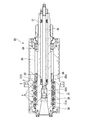
本発明のシール付アンギュラ玉軸受1が適用される主軸装置は、図1のものに限定されるものでなく、図5に示すようなツールクランプ方式のものであってもよく、任意の主軸装置に適用可能である。
In addition, this invention is not limited to the said embodiment, In the range which does not deviate from the summary of this invention, it can change or improve suitably.
The spindle device to which the sealed
例えば、図5に示す主軸装置30では、主軸31の中空部には、先端に工具ホルダを取り付ける為のコレット部32Aが形成されるドローバー32が皿ばね等の付勢手段33を介して前後に移動可能に配置されている。この主軸31は、前方に配置された本発明の4列のアンギュラ玉軸受1と、後方に配置された複列円筒ころ軸受34によって、ハウジング35に回転自在に支持されている。この主軸装置30においても、アンギュラ玉軸受1の外輪3は、ハウジング35の小径鍔部35Aと前蓋36との間に、外輪間座37を介して固定されており、内輪2は、これらの間に内輪間座38を配して、主軸31の段差31Aと、主軸31に形成された雄ねじ部分31Bに螺合されるナット39によって挟みつけ状態で主軸31に固定される。
For example, in the
2 内輪
2a 内輪軌道面
3 外輪
3a 外輪軌道面
4 玉
5 保持器
6,7 シール溝
8,9 シール部材
2
Claims (1)
前記内輪の内径寸法をd、前記外輪の外径寸法をDとすると、前記軸受の軸方向断面寸法X、前記軸受の径方向断面寸法(D−d)/2、玉径Daとの関係は、
1.2≦(X/Da)/{(D−d)/2/Da}≦1.4
であることを特徴とするシール付きアンギュラ玉軸受。 An inner ring having an inner ring raceway surface on an outer peripheral surface, an outer ring having an outer ring raceway surface on an inner peripheral surface, a plurality of balls arranged in a freely rollable manner between the outer ring raceway surface and the inner ring raceway surface, An angular ball bearing with a seal, comprising: a cage that holds the balls of the outer ring at predetermined intervals in the circumferential direction; and seal members that are fitted into seal grooves formed at both axial ends of the outer ring,
Assuming that the inner diameter of the inner ring is d and the outer diameter of the outer ring is D, the relationship between the axial sectional dimension X of the bearing, the radial sectional dimension (Dd) / 2 of the bearing, and the ball diameter Da is ,
1.2 ≦ (X / Da) / {(D−d) / 2 / Da} ≦ 1.4
A sealed angular contact ball bearing characterized by being
Priority Applications (1)
| Application Number | Priority Date | Filing Date | Title |
|---|---|---|---|
| JP2006060029A JP2007239801A (en) | 2006-03-06 | 2006-03-06 | Angular contact ball bearing with seal |
Applications Claiming Priority (1)
| Application Number | Priority Date | Filing Date | Title |
|---|---|---|---|
| JP2006060029A JP2007239801A (en) | 2006-03-06 | 2006-03-06 | Angular contact ball bearing with seal |
Publications (2)
| Publication Number | Publication Date |
|---|---|
| JP2007239801A true JP2007239801A (en) | 2007-09-20 |
| JP2007239801A5 JP2007239801A5 (en) | 2009-09-17 |
Family
ID=38585549
Family Applications (1)
| Application Number | Title | Priority Date | Filing Date |
|---|---|---|---|
| JP2006060029A Pending JP2007239801A (en) | 2006-03-06 | 2006-03-06 | Angular contact ball bearing with seal |
Country Status (1)
| Country | Link |
|---|---|
| JP (1) | JP2007239801A (en) |
Cited By (2)
| Publication number | Priority date | Publication date | Assignee | Title |
|---|---|---|---|---|
| WO2014013754A1 (en) * | 2012-07-19 | 2014-01-23 | 日本精工株式会社 | Angular contact ball bearing and duplex bearing |
| JP2014031862A (en) * | 2012-08-06 | 2014-02-20 | Nsk Ltd | Angular ball bearing |
Citations (3)
| Publication number | Priority date | Publication date | Assignee | Title |
|---|---|---|---|---|
| JP2003021149A (en) * | 2001-07-11 | 2003-01-24 | Nsk Ltd | Rotary support device for pulley for compressor |
| JP2003042160A (en) * | 2001-07-31 | 2003-02-13 | Nsk Ltd | Angular contact ball bearing and main bearing |
| JP2003113840A (en) * | 2001-10-09 | 2003-04-18 | Nsk Ltd | Ball bearing |
-
2006
- 2006-03-06 JP JP2006060029A patent/JP2007239801A/en active Pending
Patent Citations (3)
| Publication number | Priority date | Publication date | Assignee | Title |
|---|---|---|---|---|
| JP2003021149A (en) * | 2001-07-11 | 2003-01-24 | Nsk Ltd | Rotary support device for pulley for compressor |
| JP2003042160A (en) * | 2001-07-31 | 2003-02-13 | Nsk Ltd | Angular contact ball bearing and main bearing |
| JP2003113840A (en) * | 2001-10-09 | 2003-04-18 | Nsk Ltd | Ball bearing |
Cited By (3)
| Publication number | Priority date | Publication date | Assignee | Title |
|---|---|---|---|---|
| WO2014013754A1 (en) * | 2012-07-19 | 2014-01-23 | 日本精工株式会社 | Angular contact ball bearing and duplex bearing |
| JP2014020481A (en) * | 2012-07-19 | 2014-02-03 | Nsk Ltd | Angular contact ball bearing |
| JP2014031862A (en) * | 2012-08-06 | 2014-02-20 | Nsk Ltd | Angular ball bearing |
Similar Documents
| Publication | Publication Date | Title |
|---|---|---|
| JP2006322496A (en) | Multi-row angular ball bearing | |
| JP2008291921A (en) | Resin retainer for tapered roller bearing, and tapered roller bearing | |
| JP2007239801A (en) | Angular contact ball bearing with seal | |
| JP2007139045A (en) | Rotating shaft seal and bearing device | |
| JP2007303566A (en) | Rolling bearing with rotation sensor | |
| JP2005042894A (en) | Double row rolling bearing device | |
| JP2005098452A (en) | Rolling bearing device | |
| JP4895754B2 (en) | Rolling bearing with seal | |
| JP2006200670A (en) | Spacer for supporting bearing and bearing device including this spacer | |
| JP2014088928A (en) | Assembly method of conical roller bearing | |
| JP2009174556A (en) | Rolling bearing device | |
| JP2008169998A (en) | Duplex ball bearing and double-row ball bearing | |
| JP2008032148A (en) | Rolling bearing, sealing member for rolling bearing, and rotating shaft supporting structure of wind power generator | |
| JP2005226761A (en) | Linear motion bearing mechanism | |
| JP2006307886A (en) | Roller bearing | |
| JP2008008464A (en) | Double-row ball bearing unit | |
| JP2004156778A (en) | Bearing and method of assembling the bearing | |
| JP2006329388A (en) | Rolling bearing with seal | |
| TWI655374B (en) | Radial roller bearing | |
| JP2008256140A (en) | Tapered roller bearing | |
| JP2009210091A (en) | Automatic aligning roller bearing | |
| JP2009191939A (en) | Tapered roller bearing | |
| JP2006144815A (en) | Roller bearing | |
| JP2007010034A (en) | Double-row combined bearing and support unit | |
| JP2007331446A (en) | In-wheel motor bearing device and its carrying tool |
Legal Events
| Date | Code | Title | Description |
|---|---|---|---|
| RD04 | Notification of resignation of power of attorney |
Free format text: JAPANESE INTERMEDIATE CODE: A7424 Effective date: 20071128 |
|
| A621 | Written request for application examination |
Effective date: 20090226 Free format text: JAPANESE INTERMEDIATE CODE: A621 |
|
| A521 | Written amendment |
Effective date: 20090730 Free format text: JAPANESE INTERMEDIATE CODE: A523 |
|
| A977 | Report on retrieval |
Free format text: JAPANESE INTERMEDIATE CODE: A971007 Effective date: 20100210 |
|
| A131 | Notification of reasons for refusal |
Effective date: 20100302 Free format text: JAPANESE INTERMEDIATE CODE: A131 |
|
| A02 | Decision of refusal |
Free format text: JAPANESE INTERMEDIATE CODE: A02 Effective date: 20100706 |