JP2007220080A - Light-pointing device and light-tracking receiver having function selection key, and device using them - Google Patents
Light-pointing device and light-tracking receiver having function selection key, and device using them Download PDFInfo
- Publication number
- JP2007220080A JP2007220080A JP2006323326A JP2006323326A JP2007220080A JP 2007220080 A JP2007220080 A JP 2007220080A JP 2006323326 A JP2006323326 A JP 2006323326A JP 2006323326 A JP2006323326 A JP 2006323326A JP 2007220080 A JP2007220080 A JP 2007220080A
- Authority
- JP
- Japan
- Prior art keywords
- optical
- light beam
- tracking
- flicker
- light
- Prior art date
- Legal status (The legal status is an assumption and is not a legal conclusion. Google has not performed a legal analysis and makes no representation as to the accuracy of the status listed.)
- Pending
Links
Images

Classifications
-
- G—PHYSICS
- G06—COMPUTING OR CALCULATING; COUNTING
- G06F—ELECTRIC DIGITAL DATA PROCESSING
- G06F3/00—Input arrangements for transferring data to be processed into a form capable of being handled by the computer; Output arrangements for transferring data from processing unit to output unit, e.g. interface arrangements
- G06F3/01—Input arrangements or combined input and output arrangements for interaction between user and computer
- G06F3/03—Arrangements for converting the position or the displacement of a member into a coded form
- G06F3/0304—Detection arrangements using opto-electronic means
-
- G—PHYSICS
- G06—COMPUTING OR CALCULATING; COUNTING
- G06F—ELECTRIC DIGITAL DATA PROCESSING
- G06F3/00—Input arrangements for transferring data to be processed into a form capable of being handled by the computer; Output arrangements for transferring data from processing unit to output unit, e.g. interface arrangements
- G06F3/01—Input arrangements or combined input and output arrangements for interaction between user and computer
- G06F3/03—Arrangements for converting the position or the displacement of a member into a coded form
- G06F3/033—Pointing devices displaced or positioned by the user, e.g. mice, trackballs, pens or joysticks; Accessories therefor
- G06F3/0346—Pointing devices displaced or positioned by the user, e.g. mice, trackballs, pens or joysticks; Accessories therefor with detection of the device orientation or free movement in a 3D space, e.g. 3D mice, 6-DOF [six degrees of freedom] pointers using gyroscopes, accelerometers or tilt-sensors
Landscapes
- Engineering & Computer Science (AREA)
- General Engineering & Computer Science (AREA)
- Theoretical Computer Science (AREA)
- Human Computer Interaction (AREA)
- Physics & Mathematics (AREA)
- General Physics & Mathematics (AREA)
- Position Input By Displaying (AREA)
Abstract
Description
本発明は機能選択キーを有する光ポインティング装置及び光トラッキング受信器並びにこれらを用いる装置に関し、さらに詳しくは、非接触光スポットで、カーソルの制御及び所望の機能の選択を行う装置に関する。 The present invention relates to an optical pointing device having a function selection key, an optical tracking receiver, and a device using the same, and more particularly to a device for controlling a cursor and selecting a desired function with a non-contact light spot.
現在、ポンティングデバイス(例えば、ローラーボールマウス、光学マウス等)は、入力インターフェースと接触面の間の相対運動の検知に基づいてターゲット(またはカーソル)の位置をトラッキングする。通常のローラーボールマウスが面上を移動すると、マウス内部のローラーボールが回転して、一組の光エンコーダーを駆動することができる。これらの光エンコーダーがX方向及びY方向に沿う移動のステップ数を同時に計算する。ステップ数に関する情報にしたがって、コンピュータはそれぞれのフレーム期間中の前の位置の座標に対するカーソルの移動ベクトルを決定することができる。さらに、光学マウスは、画像センサを用いて連続的に変化する表面の画像を取り込み、画像を比較して前の位置に対する現在のカーソルの移動量を計算する。 Currently, a ponting device (eg, a rollerball mouse, an optical mouse, etc.) tracks the position of a target (or cursor) based on the detection of relative motion between the input interface and the contact surface. When a normal rollerball mouse moves on the surface, the rollerball inside the mouse rotates to drive a set of optical encoders. These optical encoders simultaneously calculate the number of steps along the X and Y directions. According to the information regarding the number of steps, the computer can determine the cursor movement vector with respect to the coordinates of the previous position during each frame period. Furthermore, the optical mouse captures a continuously changing surface image using an image sensor and compares the images to calculate the amount of current cursor movement relative to the previous position.
さらに、TVゲームを制御するためまたはTVスクリーン上に表示される電子ブックのページをめくるために、別の非接触型ポインティングデバイスが設計されている。そのようなポインティングデバイスはフレーム上のターゲットまたはカーソルの移動を制御するために赤外光ビームを放射する。実際には、フレームが表示されるスクリーンに隣接する場所に、モーショントラッキングセンサを有する光受信器が配置される。ユーザがポインティングデバイスを動かすと、複数のフレームの画像を毎秒取り込んでいるモーショントラッキングセンサが赤外光ビームの移動の連続する断続点パターンを受け取ることができる。したがって、光受信器はそれぞれのフレームにおいて生じる断続点パターンの様々な座標を比較することができ、直ちにスクリーン上のターゲットまたはカーソルの現在位置を修正する。 In addition, other contactless pointing devices have been designed to control TV games or to turn pages of an electronic book displayed on a TV screen. Such pointing devices emit an infrared light beam to control the movement of the target or cursor on the frame. In practice, an optical receiver having a motion tracking sensor is disposed adjacent to the screen on which the frame is displayed. As the user moves the pointing device, a motion tracking sensor that captures multiple frames of images every second can receive a continuous pattern of intermittence of infrared light beam movement. Thus, the optical receiver can compare the various coordinates of the interrupt pattern occurring in each frame and immediately corrects the current position of the target or cursor on the screen.
しかし、ポインティングデバイスはターゲットまたはカーソルの表示された位置しか制御できず、TVゲームまたは電子ブックの機能選択のための要件(例えば、スクリーン上の機能アイコンまたはページめくりボタンのクリック)を満たすことはできない。したがって、現在のTVゲーム市場では、カーソルの位置の制御及び対話式機能選択の可能化のいずれも行うことができる光ポインティング/受信装置がTVゲーム機及び電子ブックのリアルタイムで対話式のエンタテイメント効果を向上させるために緊急に必要とされている。 However, the pointing device can only control the displayed position of the target or cursor, and cannot satisfy the requirements for selecting a function of a TV game or an ebook (for example, clicking a function icon or a page turning button on the screen) . Therefore, in the current TV game market, the optical pointing / receiving device capable of both controlling the cursor position and enabling the interactive function selection has an interactive entertainment effect in real time on the TV game machine and the electronic book. There is an urgent need to improve.
本発明の課題は、機能選択キーを有する光ポインティングデバイス及び光トラッキング受信器並びにこれらを用いる装置を提供することである。光ポインティングデバイス上の様々な選択キーへの応答における実行は光ビームのフリッカー周波数によって識別され、光トラッキング受信器は受信される光スポットのフリッカー周波数にしたがって特定の機能の開始を決定する。 An object of the present invention is to provide an optical pointing device and an optical tracking receiver having a function selection key, and an apparatus using them. Execution in response to various selection keys on the optical pointing device is identified by the flicker frequency of the light beam, and the optical tracking receiver determines the start of a particular function according to the flicker frequency of the received light spot.
上記課題を達成するため、本発明は機能選択キーを有する光ポインティングデバイス及び光トラッキング受信器並びにこれらを用いる装置を開示する。光ポインティングデバイスは光ビームを発生し、機能選択キーによって光ビームを光フリッカーモードに切り換える。機能選択キーが異なれば起発される光ビームフリッカーの周波数も異なる。光ビームの断続点画像がトラッキング受信器によって検出される複数のフレームに形成される。トラッキング受信器はフリッカー周波数すなわち連続する複数のフレームにおける断続点画像の断続間隔モードにしたがって特定の機能の開始を決定する。 To achieve the above object, the present invention discloses an optical pointing device and an optical tracking receiver having a function selection key, and an apparatus using the same. The optical pointing device generates a light beam and switches the light beam to a light flicker mode by a function selection key. If the function selection key is different, the frequency of the emitted light beam flicker is also different. Intermittent images of the light beam are formed in a plurality of frames that are detected by the tracking receiver. The tracking receiver determines the start of a specific function according to the flicker frequency, i.e. the intermittent interval mode of the intermittent image in a plurality of consecutive frames.
フレームはいくつかの領域を定め、それぞれの領域は様々な機能ブロックを示すために対応する座標で囲まれる。光ビームの断続点パターンが対応する座標で囲まれたある機能ブロックを表す領域に現れ、その機能ブロックに対応する機能選択キーが起動されると、その機能ブロックで定められる機能が開始される。 The frame defines several regions, each region is surrounded by corresponding coordinates to indicate various functional blocks. When the intermittent pattern of the light beam appears in an area representing a certain function block surrounded by the corresponding coordinates and the function selection key corresponding to the function block is activated, the function defined by the function block is started.
添付図面にしたがって本発明を説明する。 The present invention will be described with reference to the accompanying drawings.
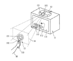
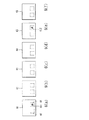
図1は本発明の光ポインティング/受信装置の応用の略図を示す。ユーザ80は光ポインティングデバイス13を動かしてTV11のスクリーン上に表示されるTVフレーム111にあるカーソル112またはターゲットの移動を制御することができる。光ポインティングデバイス13の前面に発光部131が配されている。光ビームを発生することができる発光部131は通常、環境における可視光の干渉を防止するために赤外線を放射する。機能選択キー132が光ポインティングデバイス13の手持ち部分133上に配されている。機能選択キー132が押し下げられると、発光部131から発生される光ビームは、光ビームが交互に明るくなり、暗くなる、光フリッカーモードに切り換えられる。異なる機能選択キー132には対応して異なるフリッカー周波数を割り当てても差し支えない。
FIG. 1 shows a schematic diagram of the application of the optical pointing / receiving apparatus of the present invention. The
発光部131から放射される赤外線はフィルタ121及び広角レンズ122を通過し、次いでトラッキング受信器12内部の光電素子に入る。赤外線の断続点画像が、検出される様々なフレームに形成され、トラッキング受信器12は、点々をつないで線にすることによって、検出された断続点画像を直ちにTVフレーム111のカーソル112に変換する。カーソル112がそれぞれの機能ブロック113に移動され、対応する機能選択キー132が押されると、それぞれの機能ブロック113によって定められる、次のページに進むかまたは前のページに戻るというような機能が開始され、実行される。さらに、広角レンズ122の前面にフレーム座標に対応する有効検出範囲及び有効検出領域14が定められる。ユーザ80が有効検出領域14の外側に光ビームを動かすと、カーソル112の移動を制御することはできない。
Infrared rays emitted from the
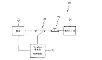
図2は本発明の光ポインティングデバイス13の光発生回路の略図である。光ポインティングデバイス13の光発生回路20は、電源ユニット24,電源スイッチ23,切換スイッチ22,フリッカー周波数制御回路25及び発光ダイオード(LED)21を有する。電源スイッチ32は電源ユニット24を直接制御してLED21に電力を供給する。光ポインティングデバイス13上の機能選択キー132の1つが押し下げられると、切換スイッチ22がフリッカー周波数制御回路25に切り換えられるであろう。したがって、LED21はフリッカー周波数制御回路25からのパルス電流出力を受け取り、周波数が一定のフリッカー光ビームを発生する。
FIG. 2 is a schematic diagram of the light generation circuit of the
図3は本発明のトラッキング受信器12の光トラッキング/受信回路30の略図である。光トラッキング/受信回路30は、相補型金属―酸化物−半導体(CMOS)センサ31,デジタル信号プロセッサ(DSP)32,ユニバーサル非同期型レシーバートランスミッター(UART)インターフェース33及び中央処理ユニット(CPU)34を有する。CMOSセンサ31が複数のフレームの連続画像の光信号をデジタル信号に変換する。次いでDSP32が、それぞれのフレームにおいて検出されたオブジェクトの品質、寸法、形状及び座標のパラメータのデジタル信号を得るために、デジタル信号にデータ圧縮及びデータフィルタリングをかける。次いでUARTインターフェース33が得られたデジタル信号を、CPU34が光スポットの位置及び移動ベクトルを決定できるように、シリアル信号に変換する。圧縮及びフィルタリングされた後はデータ量が小さくなるから、光トラッキング/受信回路30は毎秒200フレーム(200FPS)を取り込んで処理することができる。CPU34は次いで連続フレームにおける光スポットの位置及び周波数(すなわち断続間隔)にしたがってどの機能が開始されるべきであるかを決定する。
FIG. 3 is a schematic diagram of the optical tracking / receiving
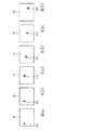
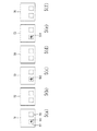
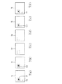
図4a〜4fは本発明のトラッキング受信器12によって取り込まれる連続フレームの略図である。図2を再び参照すれば、光発生回路20がフリッカー周波数制御回路25に切り換えられていないときには、光スポットの断続点パターン411〜416がフレーム41〜46で検出される。しかし、光発生回路20がフリッカー周波数制御回路25に切り換えられると、LED21は相異なる機能選択キー132によって要求される周波数にしたがうフリッカー光ビームを発生するであろう。例えば、上側の機能選択キー132が押されると、光は毎秒100回のフリッカーを示すであろう。したがって、毎秒200フレームを処理することができるトラッキング受信器12は図5a〜5fに示されるように連続フレーム51〜56を受信する。フレーム51〜56は、それぞれ異なる座標範囲を占める、2つの機能ブロック57及び59を有する。光スポットの断続点パターン511〜513が機能ブロック57に間欠的に現れ、機能ブロック57に受け入れられる毎秒100回のフリッカー周波数を有していると、機能ブロック57によって定められる機能が開始される。図5a〜5fの断続点パターン511〜513は2フレーム毎に現れ、よってCPU34はフリッカー周波数が毎秒100回であると計算することができる。
4a-4f are schematic diagrams of successive frames captured by the
同様に、図6a〜6fに示されるように、機能ブロック69が毎秒70回のフリッカーを示す光スポットを受け取らない限りその機能を開始できなければ、断続点パターン611〜612はフレーム61〜66の間で4フレーム毎に検出される。さらに、機能ブロック67は毎秒100回のフリッカーを示す光スポットでしか起動されない座標範囲を有するように構成される。すなわち、CPU34は4フレーム毎に断続点パターン612が現れなければ機能ブロック69によって定められる機能を実施しないであろう。
Similarly, as shown in FIGS. 6a-6f, if the
上述した光フリッカーモードに加えて、図7a〜7fは本発明のトラッキング受信器12で受け入れられる光スポットの別の断続間隔モードを示す。図7a〜7fにおいて、連続フレーム71〜76の断続点パターン711〜714は隣り合う2つのフレーム71〜72のそれぞれの機能ブロック77に現れた後、次の2つのフレーム73〜74の機能ブロック77から消え、上述したモードにしたがって出現及び消失を続けるであろう。本発明の光ポインティングデバイス13の光フリッカーモードが実施形態に説明される断続間隔態様に限定されず、同様に、トラッキング受信器12が定義に基づく様々なフリッカーモードの断続点パターンを受信できることは明らかである。
In addition to the optical flicker mode described above, FIGS. 7a-7f show another intermittent interval mode of the light spot accepted by the
本発明の上述した形態は説明だけを目的にしている。添付される特許請求の範囲を逸脱することのない数多くの別の実施形態が当業者によって案出され得る。 The above-described form of the invention is for illustrative purposes only. Numerous other embodiments may be devised by those skilled in the art without departing from the scope of the appended claims.
11 TV
12 トラッキング受信器
13 光ポインティングデバイス
14 有効検出領域
20 光発生回路
21 発光ダイオード(LED)
22 切換スイッチ
23 電源スイッチ
24 電源ユニット
25 フリッカー周波数制御回路
30 光トラッキング受信回路
31 相補型金属―酸化物−半導体(CMOS)センサ
32 デジタル信号プロセッサ(DSP)
33 ユニバーサル非同期型レシーバートランスミッター(UART)インターフェース
34 中央処理ユニット(CPU)
80 ユーザ
111 TVフレーム
112 カーソル
113 機能ブロック
121 フィルタ
122 広角レンズ
131 発光部
132 機能選択キー
133 手持ち部分
11 TV
12
22
33 Universal Asynchronous Receiver / Transmitter (UART)
80
Claims (17)
光ビームを放射するための発光部、
前記発光部を駆動してフリッカー光ビームを放射するための電力を発生するためのフリッカー周波数制御回路、及び
前記フリッカー周波数制御回路によって駆動されて前記フリッカー光ビームを放射するように前記発光部を切り換えるための少なくとも1つの機能選択キー、
を備えることを特徴とする光ポインティングデバイス。 In an optical pointing device having a function selection key,
A light emitting part for emitting a light beam,
A flicker frequency control circuit for generating power for driving the light emitting unit to emit a flicker light beam; and switching the light emitting unit to emit the flicker light beam driven by the flicker frequency control circuit. At least one function selection key for,
An optical pointing device comprising:
複数のフレームからなる連続画像を取り込み、前記連続画像の少なくとも1つの光信号を少なくとも1つのデジタル信号に変換するための画像センサ、
前記デジタル信号を処理し、少なくとも1つの出力信号を出力するためのデジタル信号プロセッサ(DSP)、及び
前記DSPからの前記出力信号に基づいて前記複数のフレームにおける特定のパターンの位置及び周波数を確認するための中央処理ユニット(CPU)、
を備えることを特徴とする光トラッキング受信器。 In an optical tracking receiver for tracking and receiving a light beam from an optical pointing device,
An image sensor for capturing a continuous image comprising a plurality of frames and converting at least one optical signal of the continuous image into at least one digital signal;
A digital signal processor (DSP) for processing the digital signal and outputting at least one output signal; and confirming positions and frequencies of specific patterns in the plurality of frames based on the output signal from the DSP Central processing unit (CPU) for
An optical tracking receiver comprising:
光ビームを発生し、少なくとも1つの機能選択キーによって前記光ビームを光フリッカーモードに切り換えるための機能選択キーを有する、光ポインティングデバイス、及び
前記光ビームの画像を有する連続する複数のフレームの画像を連続的に取り込み、前記連続する複数のフレームにおける前記光ビームの前記画像の周波数及び位置にしたがって特定の機能を開始するか否かを決定するための、光トラッキング受信器、
を備えることを特徴とする光ポインティング/トラッキング/受信装置。 In an optical pointing / tracking / receiving apparatus with function selection,
An optical pointing device having a function selection key for generating a light beam and switching the light beam to an optical flicker mode by at least one function selection key; and an image of a plurality of consecutive frames having an image of the light beam. An optical tracking receiver for continuously capturing and determining whether to initiate a specific function according to the frequency and position of the image of the light beam in the consecutive frames;
An optical pointing / tracking / receiving apparatus.
Applications Claiming Priority (1)
| Application Number | Priority Date | Filing Date | Title |
|---|---|---|---|
| TW095105012A TWI306572B (en) | 2006-02-15 | 2006-02-15 | Light pointing device and light tracking receiver having function selection key and system using the same |
Related Child Applications (1)
| Application Number | Title | Priority Date | Filing Date |
|---|---|---|---|
| JP2010047734A Division JP2010152924A (en) | 2006-02-15 | 2010-03-04 | Light-pointing device and light-tracking receiver having function selection key and system using the same |
Publications (1)
| Publication Number | Publication Date |
|---|---|
| JP2007220080A true JP2007220080A (en) | 2007-08-30 |
Family
ID=38367853
Family Applications (2)
| Application Number | Title | Priority Date | Filing Date |
|---|---|---|---|
| JP2006323326A Pending JP2007220080A (en) | 2006-02-15 | 2006-11-30 | Light-pointing device and light-tracking receiver having function selection key, and device using them |
| JP2010047734A Pending JP2010152924A (en) | 2006-02-15 | 2010-03-04 | Light-pointing device and light-tracking receiver having function selection key and system using the same |
Family Applications After (1)
| Application Number | Title | Priority Date | Filing Date |
|---|---|---|---|
| JP2010047734A Pending JP2010152924A (en) | 2006-02-15 | 2010-03-04 | Light-pointing device and light-tracking receiver having function selection key and system using the same |
Country Status (3)
| Country | Link |
|---|---|
| US (1) | US8933883B2 (en) |
| JP (2) | JP2007220080A (en) |
| TW (1) | TWI306572B (en) |
Cited By (1)
| Publication number | Priority date | Publication date | Assignee | Title |
|---|---|---|---|---|
| JP2010028820A (en) * | 2008-07-23 | 2010-02-04 | Pixart Imaging Inc | Wide-angle sensor array module, and image calibration method therefor, and operation method and application |
Families Citing this family (5)
| Publication number | Priority date | Publication date | Assignee | Title |
|---|---|---|---|---|
| US7796116B2 (en) | 2005-01-12 | 2010-09-14 | Thinkoptics, Inc. | Electronic equipment for handheld vision based absolute pointing system |
| US8913003B2 (en) | 2006-07-17 | 2014-12-16 | Thinkoptics, Inc. | Free-space multi-dimensional absolute pointer using a projection marker system |
| US9176598B2 (en) | 2007-05-08 | 2015-11-03 | Thinkoptics, Inc. | Free-space multi-dimensional absolute pointer with improved performance |
| AT506617B1 (en) * | 2008-02-27 | 2011-03-15 | Isiqiri Interface Tech Gmbh | DISPLAY AREA AND COMBINED CONTROL DEVICE |
| US8525786B1 (en) * | 2009-03-10 | 2013-09-03 | I-Interactive Llc | Multi-directional remote control system and method with IR control and tracking |
Family Cites Families (14)
| Publication number | Priority date | Publication date | Assignee | Title |
|---|---|---|---|---|
| US5933132A (en) * | 1989-11-07 | 1999-08-03 | Proxima Corporation | Method and apparatus for calibrating geometrically an optical computer input system |
| WO1995020787A1 (en) * | 1994-01-27 | 1995-08-03 | Exos, Inc. | Multimode feedback display technology |
| US6906699B1 (en) * | 1998-04-30 | 2005-06-14 | C Technologies Ab | Input unit, method for using the same and input system |
| US6501518B2 (en) * | 1998-07-28 | 2002-12-31 | Intel Corporation | Method and apparatus for reducing flicker effects from discharge lamps during pipelined digital video capture |
| JP2001290600A (en) | 2000-04-06 | 2001-10-19 | Casio Comput Co Ltd | Coordinate input system |
| JP4697916B2 (en) * | 2000-07-07 | 2011-06-08 | キヤノン株式会社 | Coordinate input device, control method therefor, and program |
| CA2420866A1 (en) * | 2000-08-28 | 2002-03-07 | Cognitens, Ltd. | Accurately aligning images in digital imaging systems by matching points in the images |
| US6704000B2 (en) * | 2000-11-15 | 2004-03-09 | Blue Iris Technologies | Method for remote computer operation via a wireless optical device |
| US7039253B2 (en) * | 2001-07-24 | 2006-05-02 | Casio Computer Co., Ltd. | Image display device, image display method, program, and projection system |
| JP2003108305A (en) * | 2001-09-28 | 2003-04-11 | Fuji Photo Optical Co Ltd | Presentation system |
| US6724368B2 (en) | 2001-12-14 | 2004-04-20 | Koninklijke Philips Electronics N.V. | Remote control system and method for a television receiver |
| US7623115B2 (en) * | 2002-07-27 | 2009-11-24 | Sony Computer Entertainment Inc. | Method and apparatus for light input device |
| JP2004164142A (en) | 2002-11-12 | 2004-06-10 | Totoku Electric Co Ltd | Optical coordinate input pen and coordinate input device |
| US7626575B2 (en) * | 2003-03-28 | 2009-12-01 | Samsung Electronics Co., Ltd. | Light pen |
-
2006
- 2006-02-15 TW TW095105012A patent/TWI306572B/en not_active IP Right Cessation
- 2006-10-30 US US11/554,404 patent/US8933883B2/en active Active
- 2006-11-30 JP JP2006323326A patent/JP2007220080A/en active Pending
-
2010
- 2010-03-04 JP JP2010047734A patent/JP2010152924A/en active Pending
Cited By (1)
| Publication number | Priority date | Publication date | Assignee | Title |
|---|---|---|---|---|
| JP2010028820A (en) * | 2008-07-23 | 2010-02-04 | Pixart Imaging Inc | Wide-angle sensor array module, and image calibration method therefor, and operation method and application |
Also Published As
| Publication number | Publication date |
|---|---|
| JP2010152924A (en) | 2010-07-08 |
| US20070188447A1 (en) | 2007-08-16 |
| TWI306572B (en) | 2009-02-21 |
| TW200730222A (en) | 2007-08-16 |
| US8933883B2 (en) | 2015-01-13 |
Similar Documents
| Publication | Publication Date | Title |
|---|---|---|
| CN101238428B (en) | Free-space pointing and handwriting | |
| KR100714722B1 (en) | Apparatus and method for implementing a pointing user interface using a signal from a light source | |
| US8188973B2 (en) | Apparatus and method for tracking a light pointer | |
| JP4927021B2 (en) | Cursor control device and control method for image display device, and image system | |
| JP5581817B2 (en) | Control system, control device, handheld device, control method and program. | |
| WO2009061619A2 (en) | Apparatus and method for tracking a light pointer | |
| JP2010152924A (en) | Light-pointing device and light-tracking receiver having function selection key and system using the same | |
| JP2010244484A (en) | Image display device, image display method and image display program | |
| US20160187996A1 (en) | Apparatus and methods for image/sensory processing to control computer operations | |
| JP2000259340A (en) | Input device and method, input system, and providing medium | |
| US10852848B2 (en) | Interactive system having angle snap | |
| US20080244466A1 (en) | System and method for interfacing with information on a display screen | |
| JP2012053584A (en) | Information display system and program | |
| JP2011138503A (en) | Object detection device | |
| JP5291560B2 (en) | Operating device | |
| JP4836099B2 (en) | Input system and method, and computer program | |
| CN102106099B (en) | Mapping detected movement of the interference pattern of coherent beams to cursor movement for user interface navigation | |
| JP4112878B2 (en) | Coordinate detection device | |
| TWI607343B (en) | Information technology device input systems and associated methods | |
| JP2007088835A (en) | Apparatus control unit | |
| JP4687820B2 (en) | Information input device and information input method | |
| KR20070119267A (en) | Apparatus and method having a contactless mouse function | |
| JP2006338328A (en) | Operation system, processor, indicating device, operating method, and program | |
| US8575552B2 (en) | System and method for distinguishing and detecting multiple infrared signal coordinates | |
| JP2007213197A (en) | Coordinate designation device |
Legal Events
| Date | Code | Title | Description |
|---|---|---|---|
| A131 | Notification of reasons for refusal |
Free format text: JAPANESE INTERMEDIATE CODE: A131 Effective date: 20090507 |
|
| A601 | Written request for extension of time |
Free format text: JAPANESE INTERMEDIATE CODE: A601 Effective date: 20090807 |
|
| A602 | Written permission of extension of time |
Free format text: JAPANESE INTERMEDIATE CODE: A602 Effective date: 20090812 |
|
| A521 | Request for written amendment filed |
Free format text: JAPANESE INTERMEDIATE CODE: A523 Effective date: 20090907 |
|
| A02 | Decision of refusal |
Free format text: JAPANESE INTERMEDIATE CODE: A02 Effective date: 20091104 |
|
| A521 | Request for written amendment filed |
Free format text: JAPANESE INTERMEDIATE CODE: A523 Effective date: 20100304 |
|
| A911 | Transfer to examiner for re-examination before appeal (zenchi) |
Free format text: JAPANESE INTERMEDIATE CODE: A911 Effective date: 20100420 |