JP2007209263A - Unit type carrier for microorganism of bioreactor - Google Patents

Unit type carrier for microorganism of bioreactor Download PDF

Info

Publication number
JP2007209263A
JP2007209263A JP2006032962A JP2006032962A JP2007209263A JP 2007209263 A JP2007209263 A JP 2007209263A JP 2006032962 A JP2006032962 A JP 2006032962A JP 2006032962 A JP2006032962 A JP 2006032962A JP 2007209263 A JP2007209263 A JP 2007209263A
Authority
JP
Japan
Prior art keywords
holding frame
bioreactor
microbial carrier
carrier element
rigid holding
Prior art date
Legal status (The legal status is an assumption and is not a legal conclusion. Google has not performed a legal analysis and makes no representation as to the accuracy of the status listed.)
Granted
Application number
JP2006032962A
Other languages
Japanese (ja)
Other versions
JP4817426B2 (en
Inventor
Yoshitaka Togo
芳孝 東郷
Teruhiko Yoshida
輝彦 吉田
Current Assignee (The listed assignees may be inaccurate. Google has not performed a legal analysis and makes no representation or warranty as to the accuracy of the list.)
Kajima Corp
Original Assignee
Kajima Corp
Priority date (The priority date is an assumption and is not a legal conclusion. Google has not performed a legal analysis and makes no representation as to the accuracy of the date listed.)
Filing date
Publication date
Application filed by Kajima Corp filed Critical Kajima Corp
Priority to JP2006032962A priority Critical patent/JP4817426B2/en
Publication of JP2007209263A publication Critical patent/JP2007209263A/en
Application granted granted Critical
Publication of JP4817426B2 publication Critical patent/JP4817426B2/en
Expired - Fee Related legal-status Critical Current
Anticipated expiration legal-status Critical

Links

Images

Classifications

    • YGENERAL TAGGING OF NEW TECHNOLOGICAL DEVELOPMENTS; GENERAL TAGGING OF CROSS-SECTIONAL TECHNOLOGIES SPANNING OVER SEVERAL SECTIONS OF THE IPC; TECHNICAL SUBJECTS COVERED BY FORMER USPC CROSS-REFERENCE ART COLLECTIONS [XRACs] AND DIGESTS
    • Y02TECHNOLOGIES OR APPLICATIONS FOR MITIGATION OR ADAPTATION AGAINST CLIMATE CHANGE
    • Y02EREDUCTION OF GREENHOUSE GAS [GHG] EMISSIONS, RELATED TO ENERGY GENERATION, TRANSMISSION OR DISTRIBUTION
    • Y02E50/00Technologies for the production of fuel of non-fossil origin
    • Y02E50/30Fuel from waste, e.g. synthetic alcohol or diesel
    • YGENERAL TAGGING OF NEW TECHNOLOGICAL DEVELOPMENTS; GENERAL TAGGING OF CROSS-SECTIONAL TECHNOLOGIES SPANNING OVER SEVERAL SECTIONS OF THE IPC; TECHNICAL SUBJECTS COVERED BY FORMER USPC CROSS-REFERENCE ART COLLECTIONS [XRACs] AND DIGESTS
    • Y02TECHNOLOGIES OR APPLICATIONS FOR MITIGATION OR ADAPTATION AGAINST CLIMATE CHANGE
    • Y02WCLIMATE CHANGE MITIGATION TECHNOLOGIES RELATED TO WASTEWATER TREATMENT OR WASTE MANAGEMENT
    • Y02W10/00Technologies for wastewater treatment
    • Y02W10/10Biological treatment of water, waste water, or sewage

Abstract

<P>PROBLEM TO BE SOLVED: To provide a unit type carrier for microorganism hard to form a narrow segment in filling to a bioreactor and easy to correct after filling. <P>SOLUTION: The unit type carrier for microorganism of bioreactor 1 comprises a plurality of hollow cylindrical microorganism carrier elements 20 installed on a predetermined position in a self standing rigid holding frame 10 having substantially the same height to the microorganism carrier element. A plurality of the microorganism carrier elements 20 are preferably filled in the rigid holding frame 10 in a way in which the carrier elements coherently come into contact with each other. Preferably the rigid holding frame 10 has a polygonal cross cut and the length of each side of the polygon is the multiple of the outside diameter of the carrier element 20. A position adjusting member is installed on the top end and/or bottom of the rigid holding frame 10 according to the needs. <P>COPYRIGHT: (C)2007,JPO&INPIT

Description

本発明はバイオリアクタのユニット型微生物担体に関し、とくに有機性廃水や有機性廃棄物スラリー等を微生物により分解処理するバイオリアクタ内で用いるユニット型微生物担体に関する。本発明は、バイオリアクタ内で長期間使用するメタン発酵微生物の固定床として有効に利用できる。   The present invention relates to a unit type microbial carrier of a bioreactor, and more particularly to a unit type microbial carrier used in a bioreactor that decomposes organic waste water, organic waste slurry, or the like with microorganisms. The present invention can be effectively used as a fixed bed of methane fermentation microorganisms used for a long time in a bioreactor.

有機性廃水や有機性廃棄物スラリー等の有機性処理液を微生物の固定床が設けられたバイオリアクタ(生物処理槽)に導き、固定床に付着した微生物と接触させ、微生物の消化作用により分解処理する生物処理が行われている。処理効率化の観点からバイオリアクタ内の固定床は、微生物を高濃度に付着させることができ、処理液との接触効率を低下させる変形や処理液残渣・余剰微生物等の固形物による閉塞が生じにくい等の条件を満たすことが要求される。   Organic treatment liquids such as organic waste water and organic waste slurry are guided to a bioreactor (biological treatment tank) equipped with a fixed bed of microorganisms, brought into contact with microorganisms attached to the fixed bed, and decomposed by the digestive action of the microorganisms. Biological treatment to be processed is performed. From the viewpoint of improving processing efficiency, the fixed bed in the bioreactor can attach microorganisms at a high concentration, resulting in deformation that reduces the contact efficiency with the processing liquid and clogging with solids such as processing liquid residues and surplus microorganisms. It is required to satisfy conditions such as difficulty.

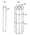
これらの条件を満たす固定床として本発明者等は、図3に示すように、ガラス繊維製の織布又は不織布により形成した多孔性の中空筒状体21を合成樹脂製の周方向及び軸方向部材からなる枠体22で支持した微生物担体素子20を開発し、特許文献1に開示した。この微生物担体素子20は、中空筒状体21の織布又は不織布の細孔に微生物を高濃度に捕捉することができ、微生物付着表面積を勘案しつつ中空筒状体21の内経の大きさを調整することにより処理液中の固形物に対する抵抗を小さくして閉塞を防止できる。また担体素子20を多数積み上げた場合でも、枠体22の形状保持能により下方の担体素子20の変形を生じない。   As shown in FIG. 3, the present inventors set the porous hollow cylindrical body 21 formed of glass fiber woven or non-woven fabric as a synthetic floor satisfying these conditions. A microbial carrier element 20 supported by a frame 22 made of a member was developed and disclosed in Patent Document 1. This microbial carrier element 20 can capture microorganisms at a high concentration in the pores of the woven or non-woven fabric of the hollow cylindrical body 21, and the inner diameter of the hollow cylindrical body 21 while taking into consideration the microbial adhesion surface area. By adjusting the resistance, the resistance to the solids in the treatment liquid can be reduced to prevent clogging. Further, even when a large number of carrier elements 20 are stacked, the lower carrier element 20 is not deformed due to the shape retaining ability of the frame 22.

また本発明者等は、バイオリアクタ内に長期間固定するメタン発酵微生物の担体素子20の材質としてガラス繊維より炭素繊維が適していることを見出し、特許文献2に開示した。ガラス繊維製の微生物担体素子20は、メタン発酵過程で発生する有機酸により酸性化しやすいバイオリアクタ内で長期間使用すると、酸性化した処理液によってガラス繊維の強度が劣化(脆弱化)し、変形や閉塞を生じる問題が経験された。炭素繊維製の微生物担体素子20は、酸に対する耐性が大きく単位面積当たりの付着微生物量も多いので、酸性化しやすいバイオリアクタ中で長期間使用しても変形や閉塞を生じにくい。炭素繊維の一例は石炭ピッチを高温で熔融紡糸し不融炭素化して得られる繊維であり、好ましくは径1〜30μmの炭素繊維からなる厚さ0.3〜6.0mm、単位重量20〜300g/m2の炭素繊維製不織布により微生物担体素子20の中空筒状体21を形成する。 In addition, the present inventors have found that carbon fiber is more suitable than glass fiber as a material for the carrier element 20 of methane fermentation microorganisms to be fixed in the bioreactor for a long time, and disclosed in Patent Document 2. When used for a long time in a bioreactor that is easily acidified by organic acids generated during the methane fermentation process, the glass fiber microbial carrier element 20 deteriorates (weakens) the strength of the glass fiber due to the acidified treatment liquid, and deforms. And problems that caused blockage were experienced. The microbial carrier element 20 made of carbon fiber has a high resistance to acid and a large amount of attached microorganisms per unit area. Therefore, even when used for a long time in a bioreactor that is easily acidified, the microbial carrier element 20 does not easily deform or clog. An example of the carbon fiber is a fiber obtained by melt spinning a coal pitch at a high temperature to convert it into an infusible carbon, preferably a thickness of 0.3 to 6.0 mm made of carbon fiber having a diameter of 1 to 30 μm, and a unit weight of 20 to 300 g / m 2. The hollow cylindrical body 21 of the microorganism carrier element 20 is formed of the carbon fiber non-woven fabric.

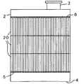
特許文献1及び2の微生物担体素子20は、例えば図4に示すように1本ずつ又は数本〜10本程度を紐24で束にして、図5に示すようにマンホール3を介してバイオリアクタ2内に搬入し、軸線を揃えて規則的に充填して固定床とする。中空筒状体21の内径が小さ過ぎると閉塞のおそれがあり、大き過ぎると微生物付着表面積が不足するが、例えば内径10〜100mm程度の微生物担体素子20をバイオリアクタ2内に規則的に充填することにより微生物の付着濃度が十分高く且つ閉塞が生じにくい固定床とすることができる。図中の符号5は微生物担体素子20を載置する孔あき受け台を示し、符号6は微生物担体素子20の浮き上がり防止用の孔あき蓋を示す。   The microbial carrier elements 20 of Patent Documents 1 and 2 are, for example, one by one as shown in FIG. 4 or a bundle of several to 10 pieces with a string 24, and a bioreactor through a manhole 3 as shown in FIG. Carry into 2 and align regularly with the axis to make a fixed bed. If the inner diameter of the hollow cylindrical body 21 is too small, there is a risk of clogging, and if it is too large, the surface area for attaching microorganisms will be insufficient. For example, a microorganism carrier element 20 having an inner diameter of about 10-100 mm is regularly packed in the bioreactor 2. Thus, it is possible to provide a fixed bed having a sufficiently high concentration of microorganisms and hardly clogging. Reference numeral 5 in the figure indicates a perforated cradle on which the microorganism carrier element 20 is placed, and reference numeral 6 indicates a perforated lid for preventing the microorganism carrier element 20 from being lifted.

実公平7−021280号公報Japanese Utility Model Publication No. 7-021280 特許第3470944号公報Japanese Patent No. 3470944

しかし、特許文献1及び2の微生物担体素子20は、バイオリアクタ2への搬入・充填の作業性を考慮すると1本の長さは2〜3mが限界であり、背の高い大型のバイオリアクタ2の固定床とする場合は、図5のように多数の微生物担体素子20を上下の軸線を一致させて複数段(図示例では3段)積み上げる必要がある。このように多数の微生物担体素子20を積み上げる作業は、非常に手間がかかると共に、上下の軸線が部分的にずれて内径が狭くなる部分(中空の狭窄部)が生じやすい問題点がある。中空の狭窄部が生じると、処理液中の固形物が堆積しやすくなり固定床の閉塞の原因となる。また、多数の微生物担体素子20を積み上げた固定床は、たとえ部分的に閉塞が生じたとしても閉塞部分だけを修復することが難しく、微生物担体素子20の全体をバイオリアクタ2から一旦搬出して新たに積み直さなければならない問題点もある。   However, in the microbial carrier element 20 of Patent Documents 1 and 2, when considering the workability of loading and filling into the bioreactor 2, the length of one microbial carrier element is limited to 2 to 3 m, and the tall and large bioreactor 2 In the case of a fixed bed, a plurality of microbial carrier elements 20 need to be stacked in a plurality of stages (three stages in the illustrated example) with their upper and lower axes aligned as shown in FIG. The operation of stacking a large number of microbial carrier elements 20 as described above is very troublesome and has a problem in that a portion (hollow constriction portion) in which the upper and lower axes are partially shifted and the inner diameter becomes narrow is easily generated. If a hollow constriction portion is generated, solid matter in the treatment liquid is likely to be deposited, which causes the fixed bed to be blocked. In addition, it is difficult to repair only the closed portion of the fixed bed on which a large number of microbial carrier elements 20 are stacked, even if a partial blockage occurs. There is also a problem that has to be reloaded.

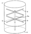
従来から、多数の微生物担体素子20の充填・修復作業の効率化や傾斜防止のため、図6に示すようにバイオリアクタ2の内部を適当な断面積の区画に分ける仕切り部材9が用いられている。図示例の仕切り部材9は、バイオリアクタ2の底板4に支持した柱部材9aから放射状に金属棒等を張り出したものであり、金属棒で仕切られた区画単位で微生物担体素子20の充填・修復を可能とする。しかし、仕切り部材9はバイオリアクタ2の構造を複雑にすると共にバイオリアクタ2の有効内容積を小さくするので、仕切り部材9で仕切れる区画数には限界がある。また、仕切り部材9を用いても微生物担体素子20の積み上げ時の軸線のずれを有効に防止することは困難である。特許文献1及び2の微生物担体素子20を用いて大型のバイオリアクタ2の固定床とするためには、多数の微生物担体素子20を狭窄部が生じないように充填し、しかも充填後に一部分のみを容易に修復できることが必要である。   Conventionally, a partition member 9 that divides the interior of the bioreactor 2 into compartments having appropriate cross-sectional areas as shown in FIG. Yes. The partition member 9 in the illustrated example is obtained by projecting a metal rod or the like radially from a column member 9a supported on the bottom plate 4 of the bioreactor 2, and filling / restoring the microbial carrier element 20 in a partition unit partitioned by the metal rod. Is possible. However, since the partition member 9 complicates the structure of the bioreactor 2 and reduces the effective internal volume of the bioreactor 2, the number of partitions partitioned by the partition member 9 is limited. Even if the partition member 9 is used, it is difficult to effectively prevent the deviation of the axis line when the microorganism carrier elements 20 are stacked. In order to use the microbial carrier element 20 of Patent Documents 1 and 2 as a fixed bed of a large bioreactor 2, a large number of microbial carrier elements 20 are filled so that no constriction occurs, and only a part is filled after filling. It must be easy to repair.

そこで本発明の目的は、バイオリアクタへの充填時に狭窄部が生じにくく且つ充填後の修復が容易であるユニット型微生物担体を提供することにある。   Therefore, an object of the present invention is to provide a unit-type microbial carrier that is less likely to cause a constriction when filling a bioreactor and that is easy to repair after filling.

図1の実施例を参照するに、本発明によるバイオリアクタのユニット型微生物担体1は、複数の中空筒状の微生物担体素子20(図3参照)をその担体素子20と実質上同じ高さの自立可能な剛性保持枠10内の所定位置に位置決めしつつ装填してなるものである。   Referring to the embodiment of FIG. 1, a unit type microbial carrier 1 of a bioreactor according to the present invention has a plurality of hollow cylindrical microbial carrier elements 20 (see FIG. 3) having substantially the same height as the carrier element 20. The self-supporting rigid holding frame 10 is loaded while being positioned at a predetermined position.

好ましくは、複数の微生物担体素子20を剛性保持枠10内に相互に密着させて充填する。更に好ましくは、剛性保持枠10を多角形断面とし、多角形断面の各辺を担体素子20の外径の整数倍とする。必要に応じて、剛性保持枠10の上端及び/又は下端に位置合わせ部材を設けることができる。   Preferably, a plurality of microbial carrier elements 20 are filled in the rigid holding frame 10 in close contact with each other. More preferably, the rigid holding frame 10 has a polygonal cross section, and each side of the polygonal cross section is an integral multiple of the outer diameter of the carrier element 20. An alignment member can be provided on the upper end and / or the lower end of the rigid holding frame 10 as necessary.

本発明のバイオリアクタのユニット型微生物担体1は、複数の中空筒状の微生物担体素子20を自立可能な剛性保持枠10内の所定位置に位置決めしつつ装填するので、次の顕著な効果を奏する。   Since the unit type microbial carrier 1 of the bioreactor of the present invention is loaded while positioning a plurality of hollow cylindrical microbial carrier elements 20 at predetermined positions within the self-supporting rigid holding frame 10, the following remarkable effects are exhibited. .

(イ)剛性保持枠10の上下方向の位置合わせにより複数の微生物担体素子20を同時に芯合わせして積層することができ、担体素子20の上下軸線のずれによる内径の狭窄部のない固定床を容易に形成できる。
(ロ)自立可能なユニット型微生物担体1を積層して固定床とすることができ、固定床の一部分が閉塞した場合に閉塞部分のユニットだけを容易に交換することが可能となる。
(ハ)また、バイオリアクタ内に微生物担体素子20の傾斜防止用の仕切り部材等を設ける必要がなくなり、バイオリアクタの構造の簡単化及び内容積の有効利用を図ることができる。
(ニ)例えば数10本〜数100本の微生物担体素子20をユニットとし、固定床をユニット単位で充填・修復できるので、従来の微生物担体素子1本又は数本〜10本ずつの充填・修復方法に比し作業効率を格段に向上できる。
(ホ)微生物担体素子を製造工場において剛性保持枠内に装填してユニット型微生物担体とすれば、搬送時の担体素子の破損を剛性保持枠で防止することができ、担体素子の破損を防止するフィルム等の梱包材料が不要となる。
(A) A plurality of microbial carrier elements 20 can be simultaneously aligned and stacked by aligning the rigid holding frame 10 in the vertical direction, and a fixed bed without a narrowed portion of the inner diameter due to the deviation of the vertical axis of the carrier element 20 can be formed. Can be easily formed.
(B) The self-supporting unit type microbial carrier 1 can be laminated to form a fixed bed. When a part of the fixed bed is blocked, only the unit of the blocked part can be easily replaced.
(C) In addition, it is not necessary to provide a partition member for preventing the inclination of the microorganism carrier element 20 in the bioreactor, and the structure of the bioreactor can be simplified and the internal volume can be effectively used.
(D) For example, several tens to several hundreds of microorganism carrier elements 20 can be used as a unit, and the fixed bed can be filled and restored in units. Work efficiency can be greatly improved compared to the method.
(E) If a microbial carrier element is loaded into a rigid holding frame in a manufacturing factory to form a unit type microbial carrier, the carrier element can be prevented from being damaged during transportation by the rigid holding frame, and the carrier element is prevented from being damaged. No packaging material such as film is required.

図1は、複数の微生物担体素子20を剛性保持枠10内に装填した本発明のユニット型微生物担体1(以下、ユニット1ということがある)の一実施例を示す。図示例の微生物担体素子20は、図3に示すように、ガラス繊維又は炭素繊維の織布又は不織布により形成した外径90mm、長さ2000mmの多孔性の中空円筒状の筒状体21を、合成樹脂製の周方向及び軸方向部材からなる枠体22で支持したものである。例えばメタン発酵を行うバイオリアクタ2では、発酵過程で発生するガス状産物により担体素子20から微生物が剥離しやすいことが知られているが、ガラス繊維又は炭素繊維の織布又は不織布は繊維間に嫌気性微生物を捕捉することにより微生物が剥離しにくく、微生物の単位面積当たりの付着量を効果的に高めることができる。また上述したように、炭素繊維製の布は酸性溶液中での強度劣化が少ないので、とくに酸性化しやすいバイオリアクタ2において長期間に亘り嫌気性微生物を安定に担持できる。   FIG. 1 shows an embodiment of a unit type microbial carrier 1 of the present invention (hereinafter sometimes referred to as a unit 1) in which a plurality of microbial carrier elements 20 are loaded in a rigid holding frame 10. As shown in FIG. 3, the microbial carrier element 20 of the illustrated example comprises a porous hollow cylindrical tubular body 21 having an outer diameter of 90 mm and a length of 2000 mm formed of a woven or non-woven fabric of glass fiber or carbon fiber. It is supported by a frame 22 made of a synthetic resin circumferential and axial member. For example, in the bioreactor 2 that performs methane fermentation, it is known that microorganisms are easily separated from the carrier element 20 by a gaseous product generated in the fermentation process. However, a woven or non-woven fabric of glass fiber or carbon fiber is interposed between the fibers. Capturing anaerobic microorganisms makes it difficult for the microorganisms to peel off, and can effectively increase the amount of microorganisms per unit area. Further, as described above, since the carbon fiber cloth has little strength deterioration in the acidic solution, the anaerobic microorganisms can be stably supported over a long period of time in the bioreactor 2 that is particularly easily acidified.

図示例の剛性保持枠10は、一辺990mmの矩形(正方形)の底端枠部材13及び頂端枠部材14と、両端枠部材13、14を結合する高さ2000mmの4本の柱枠部材15とを有する体積約2m3の直方体であり、底端枠部材13で自立可能としたものである。保持枠10は断面矩形に限らず、上下方向の位置合わせ可能な適当な断面形状、例えば多角形(正多角形)とすることができる。各枠部材13、14、15の材質は、例えば直径6mmの鋼製丸棒又は等辺山型鋼であるが、鋼管等としてもよく、バイオリアクタ2内で腐食しにくい材質又は被覆を設ければ太さ、形状等に特に制限はない。好ましくは、上段ユニット1の底端枠部材13が下段ユニット1の頂端枠部材14上に安定して載置できるように、頂端枠部材14を等辺山型とする。保持枠10が重くなると強度を大きくする必要があり、製造及び運搬コストも嵩むので、軽量の材質が望ましい。 The illustrated example of the rigid holding frame 10 includes a rectangular (square) bottom end frame member 13 and a top end frame member 14 each having a side of 990 mm, and four column frame members 15 having a height of 2000 mm for joining the both end frame members 13 and 14 together. A rectangular parallelepiped having a volume of about 2 m 3 and capable of being self-supported by the bottom end frame member 13. The holding frame 10 is not limited to a rectangular cross section, but may be an appropriate cross sectional shape that can be aligned in the vertical direction, for example, a polygon (regular polygon). The material of each of the frame members 13, 14 and 15 is, for example, a steel round bar having a diameter of 6 mm or an equilateral mountain type steel, but may be a steel pipe or the like, and thicker if a material or coating that does not easily corrode in the bioreactor 2 is provided. There is no particular limitation on the shape and the like. Preferably, the top end frame member 14 has an equilateral mountain shape so that the bottom end frame member 13 of the upper unit 1 can be stably placed on the top end frame member 14 of the lower unit 1. When the holding frame 10 becomes heavy, it is necessary to increase the strength, and the manufacturing and transportation costs increase. Therefore, a lightweight material is desirable.

また図1(C)に示すように、剛性保持枠10の底面には、保持枠10内に装填する微生物担体素子20を支えるため、微生物担体素子20の外径より小さな空隙を多数有する多孔壁11(図示例では、約76mm間隔で配置した鋼製丸棒製のグレーチング)を設けることができる。また必要に応じて、剛性保持枠10の頂面に、担体素子20の浮き上がり防止用の多孔蓋(図示せず)を設けてもよい。剛性保持枠10の頂面に多孔蓋を設ければ、後述するバイオリアクタ2内の孔あき蓋6を省略することも可能である。剛性保持枠10を補強する必要がある場合は、図示例のように、柱枠部材15の中間部分の2個所程度(例えば頂端及び底端からそれぞれ300mmの部位)に梁枠部材12を設けることができる。梁枠部材12は、剛性保持枠10内に装填した微生物担体素子20の枠外への抜け出し防止機能も果たす。   Further, as shown in FIG. 1C, a porous wall having a large number of voids smaller than the outer diameter of the microorganism carrier element 20 on the bottom surface of the rigid holding frame 10 to support the microorganism carrier element 20 loaded in the holding frame 10. 11 (in the illustrated example, a grating made of steel round bars arranged at intervals of about 76 mm) can be provided. If necessary, a porous lid (not shown) for preventing the carrier element 20 from floating may be provided on the top surface of the rigid holding frame 10. If a perforated lid is provided on the top surface of the rigid holding frame 10, the perforated lid 6 in the bioreactor 2 described later can be omitted. When it is necessary to reinforce the rigid retaining frame 10, the beam frame member 12 is provided at about two places (for example, 300 mm from the top and bottom ends) of the middle part of the column frame member 15 as shown in the example of the figure. Can do. The beam frame member 12 also functions to prevent the microbial carrier element 20 loaded in the rigid holding frame 10 from slipping out of the frame.

ユニット型微生物担体1の内部には、図1(B)に示すように微生物担体素子20を相互に密着させて縦横11列に平行に並べ、121(11×11)本装填することができる。保持枠10の矩形断面の各辺を円筒状の微生物担体素子20の外径の整数倍とし、微生物担体素子20を相互に密着させて保持枠10に規則的に充填することにより、各微生物担体素子20の軸線を保持枠10に対して位置決めできる。円筒形状の微生物担体素子20は、相互に密着させた場合も十分な隙間を設けることができるので、隙間の閉塞を生じにくい利点がある。ただし、保持枠10に対して位置決め可能であれば微生物担体素子20は円筒形に限定されず、また適当な位置決め部材等を用いて微生物担体素子20を保持枠10内の所定位置に位置決めしてもよい。   Inside the unit type microbial carrier 1, as shown in FIG. 1 (B), the microbial carrier elements 20 can be in close contact with each other and arranged in 11 rows in length and breadth, and 121 (11 × 11) can be loaded. Each side of the rectangular cross section of the holding frame 10 is an integral multiple of the outer diameter of the cylindrical microorganism carrier element 20, and the microorganism carrier elements 20 are in close contact with each other to regularly fill the holding frame 10, thereby each microorganism carrier. The axis of the element 20 can be positioned with respect to the holding frame 10. The cylindrical microbial carrier element 20 can provide a sufficient gap even when closely attached to each other, and therefore has an advantage that the gap is hardly blocked. However, the microorganism carrier element 20 is not limited to a cylindrical shape as long as it can be positioned with respect to the holding frame 10, and the microorganism carrier element 20 is positioned at a predetermined position in the holding frame 10 using an appropriate positioning member or the like. Also good.

図示例のユニット型微生物担体1は、図2に示すように、マンホール3を介してバイオリアクタ2内に搬入し、例えば底端枠部材13及び頂端枠部材14の四隅部を位置合わせ部位として上下にずれないように正確に複数積み重ねる。装填された各微生物担体素子20の軸線が保持枠10に対して位置決めされているので、保持枠1の上下方向の位置合わせにより担体素子20の各々の軸線を同時に且つ容易に芯合わせすることができる。また、剛性保持枠10を正多角形断面とすれば、各ユニット1の向きに拘わらず、底端及び頂端の隅部の位置合わせ(保持枠10の軸線の位置合わせ)により各担体素子20の軸線を芯合わせすることが可能となる。必要に応じて、底端枠部材13及び頂端枠部材14に位置合わせ部材(例えば突起)、及び保持枠10を相互に結合する結合部材等を設けてもよい。   As shown in FIG. 2, the unit type microbial carrier 1 of the illustrated example is carried into the bioreactor 2 through the manhole 3, and is vertically moved with the four corners of the bottom end frame member 13 and the top end frame member 14 as alignment parts. Accurately stack multiple items so that they do not slip. Since the axis of each loaded microorganism carrier element 20 is positioned with respect to the holding frame 10, the axes of the carrier elements 20 can be simultaneously and easily aligned by the vertical alignment of the holding frame 1. it can. Further, if the rigid holding frame 10 has a regular polygonal cross section, regardless of the direction of each unit 1, the position of each carrier element 20 is adjusted by the alignment of the bottom and top corners (the alignment of the axis of the holding frame 10). It is possible to align the axis. If necessary, the bottom end frame member 13 and the top end frame member 14 may be provided with an alignment member (for example, a protrusion) and a coupling member for coupling the holding frame 10 to each other.

すなわち本発明のユニット型微生物担体1によれば、多数の微生物担体素子20を整然と位置決めしつつバイオリアクタ2に充填できるので、従来の充填方法に比し作業時間を大幅に短縮できる。また、積層する微生物担体素子20の上下軸線のずれがほとんどなくなり、内径の狭窄部が生じにくいので、固定床の閉塞を有効に防止できる。また、自立可能なユニット1を積層して固定床とするので、固定床に閉塞が生じた場合も閉塞したユニット1のみをバイオリアクタ2からマンホール3を介して取り出すことができ、固定床の一部分の修復が容易になる。   That is, according to the unit type microbial carrier 1 of the present invention, the bioreactor 2 can be filled while positioning a large number of microbial carrier elements 20 in an orderly manner, so that the working time can be greatly reduced as compared with the conventional filling method. Further, since the vertical axis of the microbial carrier element 20 to be laminated is almost eliminated and a narrowed portion of the inner diameter is hardly generated, it is possible to effectively prevent the fixed bed from being blocked. Further, since the self-supporting units 1 are laminated to form a fixed bed, even when the fixed bed is blocked, only the blocked unit 1 can be taken out from the bioreactor 2 through the manhole 3, and a part of the fixed bed Repair becomes easier.

こうして本発明の目的である「バイオリアクタへの充填時に狭窄部が生じにくく且つ充填後の修復が容易であるユニット型微生物担体」の提供を達成することができる。   Thus, it is possible to achieve the object of the present invention, which is “a unit type microbial carrier that is less likely to cause a constriction when filled into a bioreactor and is easy to repair after filling”.

図2は、本発明のユニット型微生物担体1を充填した内径約6mのバイオリアクタ2の平面図及び断面図を示す。図示例では、バイオリアクタ2の底部にユニット載置用の孔あき受け台(グレーチング)5を設け、マンホール3から搬入したユニット1を受け台5上に相互に密着させて2段に積み上げている。断面矩形のユニット1は受け台5上の全域に敷き詰めることができないため、同図(B)に示すように、ユニット1が置けない受け台5の周縁部分には微生物担体素子20のみを従来と同様に規則的に充填して図5のような固定床を形成する。ユニット1の断面形状及び大きさは、受け台5上のできるだけ広範囲に敷き詰めることができるように工夫できる。また、受け台5の周縁部分に充填するため、断面扇方等のユニット1を用いてもよい。また積み上げた固定床の上部には、ユニット1及び微生物担体素子20が浮き上がらないように、浮き上がり防止用の孔あき蓋(グレーチング)6を設けている。   FIG. 2 shows a plan view and a cross-sectional view of a bioreactor 2 having an inner diameter of about 6 m filled with the unit type microbial carrier 1 of the present invention. In the illustrated example, a perforated cradle (grating) 5 for unit placement is provided at the bottom of the bioreactor 2, and the units 1 loaded from the manhole 3 are closely attached to each other on the cradle 5 and stacked in two stages. . Since the unit 1 having a rectangular cross section cannot be spread over the entire area of the cradle 5, as shown in FIG. 5B, only the microorganism carrier element 20 is provided on the peripheral portion of the cradle 5 where the unit 1 cannot be placed. Similarly, regular packing is performed to form a fixed bed as shown in FIG. The cross-sectional shape and size of the unit 1 can be devised so that the unit 1 can be spread over as wide a range as possible. Further, in order to fill the peripheral portion of the cradle 5, a unit 1 such as a sectional fan may be used. Further, a perforated lid (grating) 6 for preventing the unit 1 and the microorganism carrier element 20 from floating is provided on the upper part of the fixed floor.

図2のように本発明のユニット型微生物担体1を用いてバイオリアクタ2の固定床とすることにより、図6のような微生物担体素子20の傾斜防止用の仕切り部材9等を設ける必要がなくなり、バイオリアクタ2の構造を簡単化できると共に、バイオリアクタ2内の担体充足率を高めて微生物反応の効率向上も期待できる。また従来は、微生物担体素子20を製造工場から現場のバイオリアクタ2まで輸送する場合に、微生物担体素子20が破損しないよう全体を合成樹脂製フィルム等で梱包する必要があり、包装作業や包装を取り除く作業に手間がかかり、また包装フィルム等が新たな廃棄物となる等の問題も指摘されていた。本発明のユニット型微生物担体1によれば、微生物担体素子20を製造工場において剛性保持枠10内に装填した上で現場のバイオリアクタ2まで搬送することができ、搬送時の微生物担体素子20の破損を剛性保持枠10により防止できので、担体素子20の破損防止用の梱包材料等が不要となる。   By using the unit type microbial carrier 1 of the present invention as shown in FIG. 2 as a fixed bed of the bioreactor 2, there is no need to provide a partition member 9 for preventing the inclination of the microbial carrier element 20 as shown in FIG. The structure of the bioreactor 2 can be simplified, and the efficiency of the microbial reaction can be expected to increase by increasing the carrier filling rate in the bioreactor 2. Conventionally, when the microbial carrier element 20 is transported from the manufacturing plant to the on-site bioreactor 2, the entire microbial carrier element 20 must be packed with a synthetic resin film so that the microbial carrier element 20 is not damaged. It has been pointed out that the removal work takes time and the packaging film becomes a new waste. According to the unit type microbial carrier 1 of the present invention, the microbial carrier element 20 can be transported to the on-site bioreactor 2 after being loaded into the rigid holding frame 10 in the manufacturing factory. Since the breakage can be prevented by the rigid holding frame 10, a packing material for preventing the breakage of the carrier element 20 is not necessary.

本発明によるユニット型微生物担体の一実施例の説明図である。It is explanatory drawing of one Example of the unit type microorganism carrier by this invention. ユニット型微生物担体のバイオリアクタへの装填方法の説明図である。It is explanatory drawing of the loading method to the bioreactor of a unit type microbial support | carrier. 微生物担体の一例の説明図である。It is explanatory drawing of an example of a microorganism carrier. 従来の微生物担体の束ね方の説明図である。It is explanatory drawing of how to bundle the conventional microorganisms carrier. 従来の微生物担体のバイオリアクタへの装填方法の説明図である。It is explanatory drawing of the loading method to the bioreactor of the conventional microbial support | carrier. 従来の微生物担体のバイオリアクタ内での傾斜防止方法の説明図である。It is explanatory drawing of the inclination prevention method in the bioreactor of the conventional microorganism carrier.

符号の説明Explanation of symbols

1…ユニット型微生物担体 2…バイオリアクタ
3…マンホール 4…底板
5…孔あき受け台 6…孔あき蓋
9…仕切り部材 9a…柱部材
10…剛性保持枠 11…多孔壁
12…梁枠部材 13…底端枠部材
14…頂端枠部材 15…柱枠部材
20…微生物担体素子 21…中空筒状体
22…枠体 24…束ね紐
DESCRIPTION OF SYMBOLS 1 ... Unit type microorganism carrier 2 ... Bioreactor 3 ... Manhole 4 ... Bottom plate 5 ... Perforated cradle 6 ... Perforated lid 9 ... Partition member 9a ... Column member
10 ... Rigid holding frame 11 ... Perforated wall
12 ... Beam frame member 13 ... Bottom end frame member
14… Top frame member 15… Column frame member
20 ... Microorganism carrier element 21 ... Hollow cylindrical body
22 ... Frame 24 ... Bundled string

Claims (7)

複数の中空筒状の微生物担体素子を当該担体素子と実質上同じ高さの自立可能な剛性保持枠内の所定位置に位置決めしつつ装填してなるバイオリアクタのユニット型微生物担体。   A unit type microbial carrier for a bioreactor in which a plurality of hollow cylindrical microbial carrier elements are loaded while being positioned at predetermined positions in a self-supporting rigid holding frame having substantially the same height as the carrier element. 請求項1の微生物担体において、前記複数の微生物担体素子を剛性保持枠内に相互に密着させて充填してなるバイオリアクタのユニット型微生物担体。   2. The microbial carrier according to claim 1, wherein the plurality of microbial carrier elements are packed in close contact with each other in a rigid holding frame. 請求項1又は2の微生物担体において、前記剛性保持枠を多角形断面とし、当該多角形断面の各辺を前記担体素子の外径の整数倍としてなるバイオリアクタのユニット型微生物担体。   The microbial carrier according to claim 1 or 2, wherein the rigid holding frame has a polygonal cross section, and each side of the polygonal cross section is an integral multiple of the outer diameter of the carrier element. 請求項1から3の何れかの微生物担体において、前記剛性保持枠の上端及び/又は下端に位置合わせ部材を設けてなるバイオリアクタのユニット型微生物担体。   4. The microbial carrier according to claim 1, wherein an alignment member is provided on the upper end and / or the lower end of the rigid holding frame. 請求項1から4の何れかの微生物担体において、前記剛性保持枠の底面に、前記担体素子を支持する多孔壁を設けてなるバイオリアクタのユニット型微生物担体。   5. The microbial carrier according to claim 1, wherein a porous wall for supporting the carrier element is provided on the bottom surface of the rigid holding frame. 請求項1から5の何れかの微生物担体において、前記剛性保持枠の頂面に、前記担体素子の浮き上がり防止用の多孔蓋を設けてなるバイオリアクタのユニット型微生物担体。   6. The microbial carrier according to claim 1, wherein a porous lid for preventing the carrier element from being lifted is provided on the top surface of the rigid holding frame. 請求項1から6の何れかの微生物担体において、前記微生物担体素子を、ガラス繊維又は炭素繊維の織布又は不織布を円筒状に成形したものとしてなるバイオリアクタのユニット型微生物担体。   The microbial carrier according to any one of claims 1 to 6, wherein the microbial carrier element is a unit type microbial carrier of a bioreactor obtained by forming a woven or non-woven fabric of glass fiber or carbon fiber into a cylindrical shape.
JP2006032962A 2006-02-09 2006-02-09 Bioreactor unit type microbial carrier Expired - Fee Related JP4817426B2 (en)

Priority Applications (1)

Application Number Priority Date Filing Date Title
JP2006032962A JP4817426B2 (en) 2006-02-09 2006-02-09 Bioreactor unit type microbial carrier

Applications Claiming Priority (1)

Application Number Priority Date Filing Date Title
JP2006032962A JP4817426B2 (en) 2006-02-09 2006-02-09 Bioreactor unit type microbial carrier

Publications (2)

Publication Number Publication Date
JP2007209263A true JP2007209263A (en) 2007-08-23
JP4817426B2 JP4817426B2 (en) 2011-11-16

Family

ID=38488208

Family Applications (1)

Application Number Title Priority Date Filing Date
JP2006032962A Expired - Fee Related JP4817426B2 (en) 2006-02-09 2006-02-09 Bioreactor unit type microbial carrier

Country Status (1)

Country Link
JP (1) JP4817426B2 (en)

Cited By (1)

* Cited by examiner, † Cited by third party
Publication number Priority date Publication date Assignee Title
CN111269806A (en) * 2020-02-07 2020-06-12 滁州学院 Thermophilic microbial enzyme fermentation mixing stirring device

Citations (4)

* Cited by examiner, † Cited by third party
Publication number Priority date Publication date Assignee Title
JPS5153757A (en) * 1974-11-07 1976-05-12 Aisin Seiki
JPH02290297A (en) * 1989-04-28 1990-11-30 Ngk Insulators Ltd Bioreactor
JPH11207379A (en) * 1998-01-28 1999-08-03 Kajima Corp Microorganism carrier for biological treatment
JPH11267671A (en) * 1998-03-25 1999-10-05 Tokico Ltd Water purifying device

Patent Citations (4)

* Cited by examiner, † Cited by third party
Publication number Priority date Publication date Assignee Title
JPS5153757A (en) * 1974-11-07 1976-05-12 Aisin Seiki
JPH02290297A (en) * 1989-04-28 1990-11-30 Ngk Insulators Ltd Bioreactor
JPH11207379A (en) * 1998-01-28 1999-08-03 Kajima Corp Microorganism carrier for biological treatment
JPH11267671A (en) * 1998-03-25 1999-10-05 Tokico Ltd Water purifying device

Cited By (1)

* Cited by examiner, † Cited by third party
Publication number Priority date Publication date Assignee Title
CN111269806A (en) * 2020-02-07 2020-06-12 滁州学院 Thermophilic microbial enzyme fermentation mixing stirring device

Also Published As

Publication number Publication date
JP4817426B2 (en) 2011-11-16

Similar Documents

Publication Publication Date Title
US20160058182A1 (en) Cylinder storage rack system
JP4817426B2 (en) Bioreactor unit type microbial carrier
CN104334267A (en) Particulate material loading device
US5718823A (en) Device for biological wastewater treatment
CN101867265A (en) Make and transport the method for generator stator core
CN203127521U (en) Dry-mixed mortar anti-dissociation product cabin
US7934619B1 (en) Cable supported multi-chamber waste water tank
US20060131312A1 (en) Pouch assembly for use in a container
JP2014530749A (en) Fixed bed for aerobic or anaerobic wastewater purification
JP6465910B2 (en) Microorganism carrier for biological treatment and method for producing fixed bed
JP2010099008A (en) Rack for culturing mushrooms
US20150068960A1 (en) High-capacity biological contact rotor
US8281543B2 (en) Systems and methods for ballasting covers for gas-holding sludge digestors
JP2010276577A (en) Drum fixing tool and drum fixing method
CN107455312A (en) Aquaculture pond and aquaculture equipment
CN214654293U (en) Assembled domestic sewage treatment device
CN210853389U (en) Tray for plastic film
US11498752B2 (en) Digester cover left-in-place ballast ring
CN101448761A (en) Dual purpose intermodal and bioconversion container
EP2397540A1 (en) Gas storage device
CN202045119U (en) Well pipe centralizer for landfill site gas well
EP1595042B1 (en) Distillation apparatus and method of transporting the same
CN107073400A (en) Filtering module and filter plant
JP4564723B2 (en) Box storage type membrane gas holder
KR101010386B1 (en) No agitation type&#39;s composter with multilayer air supply pipe

Legal Events

Date Code Title Description
A621 Written request for application examination

Free format text: JAPANESE INTERMEDIATE CODE: A621

Effective date: 20081203

A131 Notification of reasons for refusal

Free format text: JAPANESE INTERMEDIATE CODE: A131

Effective date: 20110622

A521 Written amendment

Free format text: JAPANESE INTERMEDIATE CODE: A523

Effective date: 20110812

TRDD Decision of grant or rejection written
A01 Written decision to grant a patent or to grant a registration (utility model)

Free format text: JAPANESE INTERMEDIATE CODE: A01

Effective date: 20110829

A01 Written decision to grant a patent or to grant a registration (utility model)

Free format text: JAPANESE INTERMEDIATE CODE: A01

A61 First payment of annual fees (during grant procedure)

Free format text: JAPANESE INTERMEDIATE CODE: A61

Effective date: 20110829

FPAY Renewal fee payment (event date is renewal date of database)

Free format text: PAYMENT UNTIL: 20140909

Year of fee payment: 3

R150 Certificate of patent or registration of utility model

Free format text: JAPANESE INTERMEDIATE CODE: R150

LAPS Cancellation because of no payment of annual fees