JP2007206955A - Apparatus and method for information processing, program, and recording medium - Google Patents
Apparatus and method for information processing, program, and recording medium Download PDFInfo
- Publication number
- JP2007206955A JP2007206955A JP2006024647A JP2006024647A JP2007206955A JP 2007206955 A JP2007206955 A JP 2007206955A JP 2006024647 A JP2006024647 A JP 2006024647A JP 2006024647 A JP2006024647 A JP 2006024647A JP 2007206955 A JP2007206955 A JP 2007206955A
- Authority
- JP
- Japan
- Prior art keywords
- data
- interrupt
- information processing
- received
- processor
- Prior art date
- Legal status (The legal status is an assumption and is not a legal conclusion. Google has not performed a legal analysis and makes no representation as to the accuracy of the status listed.)
- Pending
Links
- 238000000034 method Methods 0.000 title claims abstract description 45
- 230000010365 information processing Effects 0.000 title claims description 33
- 238000004458 analytical method Methods 0.000 claims description 12
- 238000003672 processing method Methods 0.000 claims description 8
- 238000010586 diagram Methods 0.000 description 15
- 101100398248 Arabidopsis thaliana KIN10 gene Proteins 0.000 description 6
- 238000005516 engineering process Methods 0.000 description 5
- 101000835860 Homo sapiens SWI/SNF-related matrix-associated actin-dependent regulator of chromatin subfamily B member 1 Proteins 0.000 description 3
- 102100025746 SWI/SNF-related matrix-associated actin-dependent regulator of chromatin subfamily B member 1 Human genes 0.000 description 3
- 238000004891 communication Methods 0.000 description 3
- 239000000470 constituent Substances 0.000 description 3
- 101100419874 Caenorhabditis elegans snr-2 gene Proteins 0.000 description 1
- 230000004044 response Effects 0.000 description 1
- 238000007616 round robin method Methods 0.000 description 1
Images


Classifications
-
- G—PHYSICS
- G06—COMPUTING; CALCULATING OR COUNTING
- G06F—ELECTRIC DIGITAL DATA PROCESSING
- G06F13/00—Interconnection of, or transfer of information or other signals between, memories, input/output devices or central processing units
- G06F13/14—Handling requests for interconnection or transfer
- G06F13/20—Handling requests for interconnection or transfer for access to input/output bus
- G06F13/24—Handling requests for interconnection or transfer for access to input/output bus using interrupt
Abstract
Description
本発明は、情報処理装置および方法、プログラム、並びに記録媒体に関し、特に、複数のプロセッサにより、それぞれ異なるOSが実行されるコンピュータにおいて他のプロセッサやOSの処理に影響を与えることなく、正確にデータを受信させることができるようにする情報処理装置および方法、プログラム、並びに記録媒体に関する。 The present invention relates to an information processing apparatus and method, a program, and a recording medium. In particular, a computer that executes different OSs by a plurality of processors can accurately perform data processing without affecting other processors and OS processes. The present invention relates to an information processing apparatus and method, a program, and a recording medium.
近年、プロセッサの速度向上などに伴い、単一の物理計算機上で複数の仮想計算機を動作させることが可能となってきている。このような場合、通常、各仮想計算機においては異なるOS(Operating System)が動作する。 In recent years, it has become possible to operate a plurality of virtual machines on a single physical computer as the processor speed increases. In such a case, a different OS (Operating System) normally operates in each virtual machine.
このように、1つのCPU(Central Processing Unit)において複数のOSが稼動しているコンピュータなどが、他のコンピュータなどと通信を行う場合、送信されてきたパケットなどのデータがどのOSに対して受信させるべきパケットであるかを正しく判定する必要がある。このため、IPアドレスやMACアドレスなどを用いて、当該パケットを受信させるべきOSを特定する技術が提案されている(例えば、特許文献1参照)。 As described above, when a computer or the like on which a plurality of OSs are operating in one CPU (Central Processing Unit) communicates with other computers or the like, which OS receives data such as transmitted packets. It is necessary to correctly determine whether the packet is to be transmitted. For this reason, a technique for specifying an OS to receive the packet using an IP address, a MAC address, or the like has been proposed (for example, see Patent Document 1).
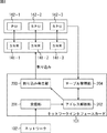
図1は、1つのCPU(Central Processing Unit)において複数のOSが稼動しているコンピュータの、パケットの受信に関する処理を行う部分の機能的構成例を示すブロック図である。ここでは、IPアドレスを用いて、当該パケットを受信させるべきOSが特定される例について説明する。 FIG. 1 is a block diagram illustrating a functional configuration example of a part that performs processing related to packet reception in a computer in which a plurality of OSs are operating in one CPU (Central Processing Unit). Here, an example will be described in which an OS that should receive the packet is specified using an IP address.
同図において、ネットワークカードインタフェース11は、通信媒体上に送信された信号を受信し、自分が受信すべきデータのフレーム(例えば、イーサネット(登録商標)フレーム)を受信する。そしてネットワークインタフェースカード11は、割り込みコントローラ12に割り込みの通知を行う。
In the figure, a
CPU13は、割り込みコントローラの制御に基づいて、割り込み処理を実行する。このとき、CPU13上で実行されるソフトウェアなどで構成されるマイクロカーネル14が、ネットワークカードインタフェース11により受信されたフレームに格納されていたデータに基づいてIPアドレスを解析し、当該フレームのデータ(パケット)を受信させるべきOSを特定する。ここで、OSの特定は、例えば、図2に示されるテーブルなど参照して行われる。
The
図2は、予め設定されたOSとIPアドレスの対応付けを表すテーブルの例を示す図である。この例では、IPアドレス「192.168.0.10」に対してOS0が対応付けられており、IPアドレス「192.168.0.11」に対してOS1が対応付けられており、IPアドレス「192.168.0.12」に対してOS2が対応付けられている。 FIG. 2 is a diagram illustrating an example of a table representing a correspondence between a preset OS and an IP address. In this example, OS0 is associated with the IP address “192.168.0.10”, OS1 is associated with the IP address “192.168.0.11”, and the IP address OS2 is associated with “192.168.0.12”.
このようにして特定されたOS0乃至OS2のいずれかに当該パケットのデータが供給されることになる。 The data of the packet is supplied to any one of OS0 to OS2 specified in this way.
また、近年では複数のプロセッサを有する情報処理装置が普及してきている。図3は、複数のプロセッサを有するコンピュータの、パケットの受信に関する処理を行う部分の機能的構成例を示すブロック図である。 In recent years, information processing apparatuses having a plurality of processors have become widespread. FIG. 3 is a block diagram illustrating a functional configuration example of a part that performs processing related to packet reception in a computer having a plurality of processors.
図3の例では、CPU0乃至CPU2により単一のOSが実行される構成とされており、いまの場合、自分が受信すべきデータのフレーム(例えば、イーサネット(登録商標)フレーム)を受信したネットワークインタフェースカード11は、割り込みコントローラ12に割り込みの通知が行われ、その後、CPU0乃至CPU2のいずれかによりパケットの受信が行われる。このとき、パケットの受信を行うCPUは、例えば、ラウンドロビン方式で選択されるようにしてもよいし、最も負荷の少ないCPUが選択されるようにしてもよいし、あるいは、予め設定されたCPUが常にパケットの受信を行うようにしてもよい。
In the example of FIG. 3, a single OS is executed by the
しかしながら、図4に示されるように複数のCPU(CPU0乃至CPU2)により、それぞれ異なるOS(OS0乃至OS2)が実行される情報処理装置においては、ラウンドロビン方式で選択されるCPUに割り込みを通知しても、実際にパケットを受信すべきOSは、別のCPUにおいて実行されている場合がある。このため、CPUに割り込みを通知する前に、予めどのOSで受信されるべきパケットであるかを解析する処理を行う必要があるが、従来の技術では、複数のCPUにより、それぞれ異なるOSが実行される情報処理装置において他のCPUやOSの処理に影響を与えることなく、正確にデータを受信させることは困難であった。 However, as shown in FIG. 4, in an information processing apparatus in which different OSs (OS0 to OS2) are executed by a plurality of CPUs (CPU0 to CPU2), an interrupt is notified to the CPU selected by the round robin method. However, the OS that should actually receive the packet may be executed in another CPU. Therefore, before notifying the interrupt to CPU, it is necessary to perform processing for analyzing whether the packet should be received in advance by any OS, in the prior art, a plurality of CPU, different OS each run It has been difficult for an information processing apparatus to receive data accurately without affecting the processing of other CPUs and OSs.
本発明はこのような状況に鑑みてなされたものであり、複数のプロセッサにより、それぞれ異なるOSが実行されるコンピュータにおいて他のプロセッサやOSの処理に影響を与えることなく、正確にデータを受信させることができるようにするものである。 The present invention has been made in view of such circumstances, and allows a plurality of processors to receive data accurately without affecting other processors and the processing of the OS in a computer on which a different OS is executed. Is to be able to.
本発明の一側面の情報処理装置は、ネットワークを介して受信したデータを、複数のプロセッサにより実行されるそれぞれ個別のOS(Operating System)により処理させる情報処理装置であって、前記ネットワークから所定の単位のデータを受信する受信手段と、前記受信手段により受信されたデータに付加された識別データを解析する解析手段と、前記識別データと、前記OSを実行するプロセッサの割り込みレジスタを特定する情報とを対応付けたテーブルを保持する保持手段と、前記保持手段に保持されるテーブルに基づいて特定される前記解析手段により解析された前記識別データに対応する前記割り込みレジスタに、前記受信手段により受信されたデータを書き込むことで、前記プロセッサに対する割り込み処理を発生させる発生手段とを備える情報処理装置である。 An information processing apparatus according to an aspect of the present invention is an information processing apparatus that processes data received via a network by individual OSs (Operating Systems) executed by a plurality of processors. Receiving means for receiving unit data, analyzing means for analyzing identification data added to the data received by the receiving means, the identification data, and information for specifying an interrupt register of a processor executing the OS; Received by the receiving means to the interrupt register corresponding to the identification data analyzed by the analyzing means specified based on the table held by the holding means and a table held by the holding means Generating means for generating interrupt processing for the processor by writing the data It is obtain the information processing apparatus.
前記受信手段により受信されるデータがIPパケットであり、前記識別情報は、前記IPパケットの宛先IPアドレスであるようにすることができる。 The data received by the receiving means may be an IP packet, and the identification information may be a destination IP address of the IP packet.
前記受信手段により受信されるデータがデータリンク層のフレームであり、前記識別情報は、前記フレームの宛先MACアドレスであるようにすることができる。 The data received by the receiving means may be a data link layer frame, and the identification information may be a destination MAC address of the frame.
前記イーサネット(登録商標)のフレームは、IEEE 802.1Qに適合する形式のフレームであり、前記識別情報は、前記フレームのタグに含まれるVLANIDであるようにすることができる。 The Ethernet (registered trademark) frame may be a frame conforming to IEEE 802.1Q, and the identification information may be a VLAN ID included in a tag of the frame.
前記複数のプロセッサは、単一のOSで実行されるそれぞれ個別のプロセスを実行し、前記保持手段は、前記識別データと、前記プロセスを実行するプロセッサの割り込みレジスタを特定する情報とを対応付けたテーブルを保持するようにすることができる。 The plurality of processors execute individual processes executed by a single OS, and the holding unit associates the identification data with information for specifying an interrupt register of a processor executing the process. A table can be held.
本発明の一側面の情報処理方法は、ネットワークを介して受信したデータを、複数のプロセッサにより実行されるそれぞれ個別のOS(Operating System)により処理させる情報処理装置の情報処理方法であって、前記ネットワークから所定の単位のデータを受信し、前記受信されたデータに付加された識別データを解析し、前記識別データと、前記OSを実行するプロセッサの割り込みレジスタを特定する情報とを対応付けたテーブルに基づいて、前記解析された前記識別データに対応する前記割り込みレジスタを特定し、特定された前記割り込みレジスタに、前記受信されたデータを書き込むことで、前記プロセッサに対する割り込み処理を発生させるステップを含む情報処理方法である。 An information processing method according to an aspect of the present invention is an information processing method for an information processing apparatus that causes data received via a network to be processed by each individual OS (Operating System) executed by a plurality of processors, A table that receives data in a predetermined unit from the network, analyzes identification data added to the received data, and associates the identification data with information for specifying an interrupt register of a processor that executes the OS And specifying the interrupt register corresponding to the analyzed identification data, and writing the received data to the specified interrupt register to generate an interrupt process for the processor. Information processing method.
本発明の一側面のプログラムは、ネットワークを介して受信したデータを、複数のプロセッサにより実行されるそれぞれ個別のOS(Operating System)により処理させる情報処理装置に情報処理方法を実行させるプログラムであって、前記ネットワークから所定の単位のデータの受信を制御し、前記受信されたデータに付加された識別データの解析を制御し、前記識別データと、前記OSを実行するプロセッサの割り込みレジスタを特定する情報とを対応付けたテーブルに基づいて、前記解析された前記識別データに対応する前記割り込みレジスタの特定を制御し、特定された前記割り込みレジスタに、前記受信されたデータを書き込むことで、前記プロセッサに対する割り込み処理の発生を制御するステップを含むコンピュータが読み取り可能なプログラムである。 A program according to one aspect of the present invention is a program for causing an information processing apparatus to process data received via a network by each individual OS (Operating System) executed by a plurality of processors, and to execute an information processing method. Information for controlling reception of data in a predetermined unit from the network, controlling analysis of identification data added to the received data, and identifying the identification data and an interrupt register of a processor executing the OS And controlling the identification of the interrupt register corresponding to the analyzed identification data, and writing the received data to the identified interrupt register. A computer-readable program that includes steps to control the occurrence of interrupt processing. A gram.
本発明の一側面においては、ネットワークから所定の単位のデータが受信され、前記受信されたデータに付加された識別データが解析され、前記識別データと、前記OSを実行するプロセッサの割り込みレジスタを特定する情報とを対応付けたテーブルに基づいて、前記解析された前記識別データに対応する前記割り込みレジスタが特定され、特定された前記割り込みレジスタに、前記受信されたデータを書き込むことで、前記プロセッサに対する割り込み処理が発生させられる。 In one aspect of the present invention, a predetermined unit of data is received from a network, identification data added to the received data is analyzed, and the identification data and an interrupt register of a processor that executes the OS are specified. The interrupt register corresponding to the analyzed identification data is identified based on the table that associates the information to be performed, and the received data is written to the identified interrupt register, whereby the processor Interrupt handling is generated.
本発明によれば、複数のプロセッサにより、それぞれ異なるOSが実行されるコンピュータにおいて他のプロセッサやOSの処理に影響を与えることなく、正確にデータを受信させることができる。 According to the present invention, data can be accurately received by a plurality of processors without affecting the processing of other processors or OSs in a computer on which different OSs are executed.
以下に本発明の実施の形態を説明するが、本発明の構成要件と、明細書または図面に記載の実施の形態との対応関係を例示すると、次のようになる。この記載は、本発明をサポートする実施の形態が、明細書または図面に記載されていることを確認するためのものである。従って、明細書または図面中には記載されているが、本発明の構成要件に対応する実施の形態として、ここには記載されていない実施の形態があったとしても、そのことは、その実施の形態が、その構成要件に対応するものではないことを意味するものではない。逆に、実施の形態が構成要件に対応するものとしてここに記載されていたとしても、そのことは、その実施の形態が、その構成要件以外の構成要件には対応しないものであることを意味するものでもない。 Embodiments of the present invention will be described below. Correspondences between constituent elements of the present invention and the embodiments described in the specification or the drawings are exemplified as follows. This description is intended to confirm that the embodiments supporting the present invention are described in the specification or the drawings. Therefore, even if there is an embodiment which is described in the specification or the drawings but is not described here as an embodiment corresponding to the constituent elements of the present invention, that is not the case. It does not mean that the form does not correspond to the constituent requirements. Conversely, even if an embodiment is described here as corresponding to a configuration requirement, that means that the embodiment does not correspond to a configuration requirement other than the configuration requirement. It's not something to do.
本発明の一側面の情報処理装置は、ネットワークを介して受信したデータを、複数のプロセッサ(例えば、図6のPU142−1乃至SPU142−3)により実行されるそれぞれ個別のOS(Operating System)により処理させる情報処理装置(例えば、図8のネットワークインタフェースカード101)であって、前記ネットワークから所定の単位のデータを受信する受信手段(例えば、図8の受信部201)と、前記受信手段により受信されたデータに付加された識別データを解析する解析手段(例えば、図8のアドレス解析部202)と、前記識別データと、前記OSを実行するプロセッサの割り込みレジスタ(例えば、図6のSNR141−1乃至141−3)を特定する情報とを対応付けたテーブルを保持する保持手段(例えば、図8のテーブル管理部204)と、前記保持手段に保持されるテーブルに基づいて特定される前記解析手段により解析された前記識別データに対応する前記割り込みレジスタに、前記受信手段により受信されたデータを書き込むことで、前記プロセッサに対する割り込み処理を発生させる発生手段(例えば、図8の割り込み発生部203)とを備える。
An information processing apparatus according to an aspect of the present invention receives data received via a network by each individual OS (Operating System) executed by a plurality of processors (for example, PU 142-1 to SPU 142-3 in FIG. 6). An information processing apparatus to be processed (for example, the
この情報処理装置は、前記複数のプロセッサが、単一のOS(例えば、図14のOS143)で実行されるそれぞれ個別のプロセス(例えば、図14のプロセス151−1乃至151−3)を実行し、前記保持手段は、前記識別データと、前記プロセスを実行するプロセッサの割り込みレジスタを特定する情報とを対応付けたテーブルを保持するようにすることができる。
In this information processing apparatus, the plurality of processors execute individual processes (for example, processes 151-1 to 151-3 in FIG. 14) executed by a single OS (for example,
本発明の一側面の情報処理方法は、ネットワークを介して受信したデータを、複数のプロセッサ(例えば、図6のPU142−1乃至SPU142−3)により実行されるそれぞれ個別のOS(Operating System)により処理させる情報処理装置(例えば、図8のネットワークインタフェースカード101)の情報処理方法であって、前記ネットワークから所定の単位のデータを受信し(例えば、図9のステップS101の処理)、前記受信されたデータに付加された識別データを解析し(例えば、図9のステップS102の処理)、前記識別データと、前記OSを実行するプロセッサの割り込みレジスタ(例えば、図6のSNR141−1乃至141−3)を特定する情報とを対応付けたテーブルに基づいて、前記解析された前記識別データに対応する前記割り込みレジスタを特定し(例えば、図9のステップS103の処理)、特定された前記割り込みレジスタに、前記受信されたデータを書き込むことで、前記プロセッサに対する割り込み処理を発生させる(例えば、図9のステップS104の処理)ステップを含む。
According to an information processing method of one aspect of the present invention, data received via a network is processed by each individual OS (Operating System) executed by a plurality of processors (for example, PU 142-1 to SPU 142-3 in FIG. 6). An information processing method of an information processing apparatus to be processed (for example, the
以下、図面を参照して、本発明の実施の形態について説明する。 Embodiments of the present invention will be described below with reference to the drawings.
図5は、本発明を適用したネットワークインタフェースカードの一実施形態に係る例を示す図である。 FIG. 5 is a diagram showing an example according to an embodiment of a network interface card to which the present invention is applied.
図5において、ネットワークインタフェースカード101は、例えば、パーソナルコンピュータやサーバなどの端末に組み込まれて使用されるように構成されている。ネットワークインタフェースカードは、自身にケーブルなどの通信媒体が接続されることで、例えば、イーサネット(登録商標)などのネットワーク102に接続され、ネットワーク102に送信される信号を取得する。
In FIG. 5, the
ネットワークインタフェースカード101は、ネットワーク102から取得した信号に対応するデータのうち、ネットワークインタフェースカード101が組み込まれた端末が受信すべきイーサネット(登録商標)フレームやIPパケットなどのデータを受信する。ネットワークインタフェースカード101が組み込まれた端末が受信すべきデータを受信した場合、ネットワークインタフェースカード101は、図示せぬ内部バスなどを介して端末のプロセッサ103に対して割り込みを通知する。
The
プロセッサ103は、ネットワークインタフェースカード101が組み込まれた端末における各種の処理を実行し、ネットワークインタフェースカード101から割り込みの通知を受けた場合、ネットワークインタフェースカード101から供給されるデータを、図示せぬメモリの所定のエリアに転送させるよう端末を構成する各部を制御する。
The
本発明を適用したネットワークインタフェースカード101は、自身がマルチコア方式の高性能プロセッサ「Cell」の技術を採用した端末に組み込み可能となるように構成されている。「Cell」の技術を採用したコンピュータなどにおいては、複数のプロセッサにより、それぞれ異なるOS(Operating System)を稼動させることが可能となる。
The
図6は、「Cell」の技術を採用したコンピュータの構成と、ネットワークインタフェースカード101の関係を説明する図である。このコンピュータ(端末)においては、複数(いまの場合、3)のプロセッサとしてPU(Processing Unit)142−1、SPU(Synergitic Processing Unit)142−2、SPU142−3が儲けられており、PU142−1乃至SPU142−3において、OS143−1乃至OS143−3が稼動しており、複数のプロセッサにおいて個別のOSがそれぞれ稼動される構成とされている。
FIG. 6 is a diagram for explaining the relationship between the configuration of a computer employing the “Cell” technology and the
「Cell」の技術を採用したコンピュータにおいては、各プロセッサ間での同期をとるため、または各プロセッサと、コンピュータに組み込まれた各種のデバイスとの間での同期をとるためのレジスタである、SNR(Signal Notification Register)がプロセッサ毎に設けられる。いまの場合、PU142−1乃至SPU142−3に対応してSNR141−1乃至SNR141−3が設けられている。 In a computer employing the “Cell” technology, the SNR is a register for synchronizing each processor, or for synchronizing each processor and various devices incorporated in the computer. (Signal Notification Register) is provided for each processor. In this case, SNR 141-1 to SNR 141-3 are provided corresponding to PU 142-1 to SPU 142-3.
例えば、コンピュータに組み込まれた各種のデバイスが、所定のプロセッサに対して割り込みを行う場合、割り込みを行うべきプロセッサに対応するSNRに割り込みが発生したこと表すデータなどを書き込む。そして、そのSNRに対応するプロセッサがSNRに書き込まれたデータに基づいて、例えば、デバイスから供給されるデータを図示せぬメモリの所定のエリアに移動させるなどの割り込み処理を実行する。 For example, when various devices incorporated in a computer interrupt a predetermined processor, data indicating that the interrupt has occurred is written in the SNR corresponding to the processor that should perform the interrupt. Then, based on the data written in the SNR, for example, the processor corresponding to the SNR executes interrupt processing such as moving data supplied from the device to a predetermined area of a memory (not shown).
複数のプロセッサにより、それぞれ異なるOSが実行される端末においては、ネットワークインタフェースカード101がデータを受信した場合、プロセッサに割り込みを通知する前に、予めどのOSで受信されるべきデータであるかを特定する必要がある。そこで、本発明においては、図7に示されるようなテーブルを参照することで、ネットワークインタフェースカード101が予めどのOSで受信されるべきデータであるかを特定する。
A plurality of processors, in a terminal different OS, respectively, are performed, identify or if the
なお、ここでは、OS143−1乃至OS143−3に対してそれぞれ異なるIPアドレスが付与されているものとする。すなわち、OS143−1には、IPアドレス「192.168.0.10」が付与されており、OS143−2には、IPアドレス「192.168.0.11」が付与されており、OS143−3には、IPアドレス「192.168.0.12」が付与されているものとする。 Here, it is assumed that different IP addresses are assigned to the OSs 143-1 to 143-3. That is, the IP address “192.168.0.10” is assigned to the OS 143-1, the IP address “192.168.0.11” is assigned to the OS 143-2, and the OS 143-3 is assigned. 3 is assigned the IP address “192.168.0.12”.
図7は、IPアドレスとSNRとを対応付けたテーブルの例を示す図である。同図において、SNR0乃至SNR2は、それぞれ図6のSNR141−1乃至SNR141−3を特定するIDとされ、IPアドレス「192.168.0.10」に対してSNR0が対応付けられており、IPアドレス「192.168.0.11」に対してSNR1が対応付けられており、IPアドレス「192.168.0.12」に対してSNR2が対応付けられている。 FIG. 7 is a diagram illustrating an example of a table in which IP addresses are associated with SNRs. In the figure, SNR0 to SNR2 are IDs for identifying SNR141-1 to SNR141-3 in FIG. 6, respectively, and SNR0 is associated with the IP address “192.168.0.10”. SNR1 is associated with the address “192.168.0.11”, and SNR2 is associated with the IP address “192.168.0.12”.
ネットワークインタフェースカード101が図7に示されるようなテーブルを参照して受信したデータ(いまの場合、IPパケット)に対応するSNRを特定すれば、他のプロセッサやOSの処理に影響を与えることなく、正確にデータを受信させることが可能となる。
If the SNR corresponding to the data (in this case, the IP packet) received by the
図8は、ネットワークインタフェースカード101の機能的構成例を示すブロック図である。
FIG. 8 is a block diagram illustrating a functional configuration example of the
ネットワークインタフェースカード101の受信部201は、ネットワーク102に送信された信号を取得し、ネットワーク102から取得した信号に対応するデータのうち、ネットワークインタフェースカード101が組み込まれた端末が受信すべきイーサネット(登録商標)フレームやIPパケットなどのデータを受信する。
The receiving
アドレス解析部202は、受信部201が受信したデータ(いまの場合、IPパケット)の宛先IPアドレスをチェックし、テーブル管理部204により記憶されているテーブルを検索する。
The address analysis unit 202 checks the destination IP address of the data (IP packet in this case) received by the
テーブル管理部204は、例えば、図7に示されるようなIPアドレスとSNRとを対応付けたテーブルを記憶しており、PU142−1乃至SPU142−3により、それぞれのプロセッサで稼動するOSに付与されたIPアドレスと、それぞれのプロセッサに対応して設けられたSNRのIDに関する情報の供給を受けて、テーブルを生成または更新し、記憶する。 The table management unit 204 stores, for example, a table in which an IP address and an SNR are associated with each other as illustrated in FIG. 7, and is assigned to the OS running on each processor by the PU 142-1 to SPU 142-3. The table is generated or updated in response to the supply of the IP address and the information related to the SNR ID provided for each processor.
割り込み発生部203は、アドレス解析部202からの指令に基づいて、所定のSNRに対してIPパケットの受信を通知することで割り込みを発生させる。すなわち、割り込み発生部203は、アドレス解析部202がテーブル管理部204により記憶されているテーブルに基づいて特定したID(例えば、SNR2)に対応するSNR(例えば、SNR141−3)にネットワークインタフェースカード101からの割り込みが発生したこと表すデータなどを書き込む。そして、そのSNRに対応するプロセッサ(例えば、SPU142−3)がSNRに書き込まれたデータに基づいて、受信部201が受信したデータを図示せぬメモリの所定のエリアに移動させる割り込み処理を実行する。
The interrupt generation unit 203 generates an interrupt by notifying reception of an IP packet to a predetermined SNR based on a command from the address analysis unit 202. That is, the interrupt generation unit 203 sets the
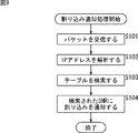
図9は、ネットワークインタフェースカード101による割り込み処理を説明するフローチャートである。
FIG. 9 is a flowchart for explaining interrupt processing by the
ステップS101において、受信部201は、ネットワーク102に送信された信号を取得し、ネットワーク102から取得した信号に対応するデータのうち、ネットワークインタフェースカード101が組み込まれた端末が受信すべきIPパケットなどのデータを受信する。
In step S101, the receiving
ステップS102において、アドレス解析部202は、受信部201が受信したIPパケットの宛先IPアドレスを解析する。
In step S102, the address analysis unit 202 analyzes the destination IP address of the IP packet received by the
ステップS103において、アドレス解析部202は、テーブル管理部204により記憶されているテーブルを検索する。このとき、例えば、図7に示されるようなテーブルが参照され、ステップS102の処理で解析されたIPアドレスに対応するSNRのIDが検索され、検索されたSNRのIDが割り込み発生部203に供給される。 In step S <b> 103, the address analysis unit 202 searches the table stored by the table management unit 204. At this time, for example, a table as shown in FIG. 7 is referred to, an SNR ID corresponding to the IP address analyzed in the process of step S102 is searched, and the searched SNR ID is supplied to the interrupt generation unit 203. Is done.
ステップS104において、割り込み発生部203は、ステップS103の処理で検索されたSNRのIDに基づいて特定されたSNRに対してIPパケットの受信を通知することで割り込みを発生させる。 In step S104, the interrupt generation unit 203 generates an interrupt by notifying the reception of the IP packet to the SNR identified based on the SNR ID searched in the process of step S103.
このようにして割り込み通知処理が行われる。このようにすることで、他のプロセッサやOSの処理に影響を与えることなく、所定のOSに正確にデータを受信させることが可能となる。 In this way, interrupt notification processing is performed. By doing so, it becomes possible to cause a predetermined OS to receive data accurately without affecting the processing of other processors and OS.
以上においては、OS143−1乃至OS143−3に対してそれぞれ異なるIPアドレスが付与されている場合の例について説明したが、OS143−1乃至OS143−3に対してそれぞれ異なるMACアドレスが付与されている場合、テーブル管理部204により生成または更新されて記憶されるテーブルは、図10に示されるようにすることがきる。 In the above, an example in which different IP addresses are assigned to the OSs 143-1 to OS143-3 has been described. However, different MAC addresses are assigned to the OSs 143-1 to OS143-3. In this case, the table generated and updated by the table management unit 204 can be stored as shown in FIG.
図10は、MACアドレスとSNRとを対応付けたテーブルの例を示す図である。同図において、SNR0乃至SNR2は、それぞれ図6のSNR141−1乃至SNR141−3を特定するIDとされ、MACアドレス「08:00:46:EA:10:BE」に対してSNR0が対応付けられており、MACアドレス「08:00:46:D2:10:C2」に対してSNR1が対応付けられており、MACアドレス「08:00:46:54:42:F7」に対してSNR2が対応付けられている。 FIG. 10 is a diagram illustrating an example of a table in which MAC addresses are associated with SNRs. In the figure, SNR0 to SNR2 are IDs for identifying SNR141-1 to SNR141-3 in FIG. 6, respectively, and SNR0 is associated with the MAC address “08: 0: 46: EA: 10: BE”. SNR1 is associated with MAC address “08: 0: 46: D2: 10: C2” and SNR2 is associated with MAC address “08: 0: 46: 54: 42: F7” It is attached.
図7を参照して上述した場合と同様に、ネットワークインタフェースカード101が図10に示されるようなテーブルを参照して受信したデータ(いまの場合、イーサネット(登録商標)などのフレーム)に対応するSNRを特定すれば、他のプロセッサやOSの処理に影響を与えることなく、正確にデータを受信させることが可能となるが、図7の場合、ネットワーク層のパケットのアドレスを解析する必要があったのに対し、図10の場合、ネットワーク層の下位の階層であるデータリンク層のフレームのアドレスを解析するだけでよいので、図7の場合と比較して、より負荷を軽減させることが可能となる。
Similarly to the case described above with reference to FIG. 7, the
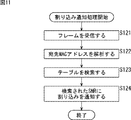
図11は、図10の場合に対応した、ネットワークインタフェースカード101による割り込み処理を説明するフローチャートである。
FIG. 11 is a flowchart for explaining interrupt processing by the
ステップS121において、受信部201は、ネットワーク102に送信された信号を取得し、ネットワーク102から取得した信号に対応するデータのうち、ネットワークインタフェースカード101が組み込まれた端末が受信すべきイーサネット(登録商標)フレームなどのデータを受信する。
In step S <b> 121, the
ステップS122において、アドレス解析部202は、受信部201が受信したフレームの宛先MACアドレスを解析する。
In step S122, the address analysis unit 202 analyzes the destination MAC address of the frame received by the
ステップS123において、アドレス解析部202は、テーブル管理部204により記憶されているテーブルを検索する。このとき、例えば、図10に示されるようなテーブルが参照され、ステップS122の処理で解析されたMACアドレスに対応するSNRのIDが検索され、検索されたSNRのIDが割り込み発生部203に供給される。 In step S123, the address analysis unit 202 searches the table stored by the table management unit 204. At this time, for example, a table as shown in FIG. 10 is referred to, an SNR ID corresponding to the MAC address analyzed in step S122 is searched, and the searched SNR ID is supplied to the interrupt generation unit 203. Is done.
ステップS124において、割り込み発生部203は、ステップS123の処理で検索されたSNRのIDに基づいて特定されたSNRに対してフレームの受信を通知することで割り込みを発生させる。 In step S124, the interrupt generation unit 203 generates an interrupt by notifying reception of a frame to the SNR identified based on the SNR ID searched in the process of step S123.
このようにして割り込み通知処理が行われる。このようにすることで、やはり他のプロセッサやOSの処理に影響を与えることなく、所定のOSに正確にデータを受信させることが可能となる。 In this way, interrupt notification processing is performed. By doing so, it is possible to cause a predetermined OS to receive data accurately without affecting the processing of other processors and OSs.
また、ネットワーク102がIEEE802.1Qに対応するネットワークである場合、OS143−1乃至OS143−3に対してそれぞれ異なるVLANIDが付与されていることもあり得る。IEEE802.1Qは、例えば、スイッチングハブを用いて構成されるバーチャルLAN(VLAN)に関する規格であり、IEEE802.1Qに適合した仕様を有するネットワーク機器により送受信される通信データおいては、イーサネット(登録商標)フレームの「Source Address」のフィールドと「Type」のフィールドの間に「Tag」のフィールドが挿入される。そして、「Tag」のフィールドに含まれるVLANIDに基づいて、そのフレームが属するVLAN(Virtual LAN)が特定されることになる。
Further, when the
OS143−1乃至OS143−3に対してそれぞれ異なるVLANIDが付与されている場合、テーブル管理部204により生成または更新されて記憶されるテーブルは、図12に示されるようにすることがきる。 When different VLAN IDs are assigned to the OSs 143-1 to 143-3, the table generated and updated by the table management unit 204 can be configured as shown in FIG.
図12は、VLANIDとSNRとを対応付けたテーブルの例を示す図である。同図において、SNR0乃至SNR2は、それぞれ図6のSNR141−1乃至SNR141−3を特定するIDとされ、VLANID「10」に対してSNR0が対応付けられており、VLANID「11」に対してSNR1が対応付けられており、VLANID「12」に対してSNR2が対応付けられている。 FIG. 12 is a diagram illustrating an example of a table in which VLAN IDs and SNRs are associated with each other. In FIG. 6, SNR0 to SNR2 are IDs that identify SNR141-1 to SNR141-3 in FIG. 6, respectively, and SNR0 is associated with VLANID “10”, and SNR1 is associated with VLANID “11”. Are associated with each other, and SNR2 is associated with VLAN ID “12”.
図13は、図12の場合に対応した、ネットワークインタフェースカード101による割り込み処理を説明するフローチャートである。
FIG. 13 is a flowchart for explaining interrupt processing by the
ステップS141において、受信部201は、ネットワーク102に送信された信号を取得し、ネットワーク102から取得した信号に対応するデータのうち、ネットワークインタフェースカード101が組み込まれた端末が受信すべきイーサネット(登録商標)フレームなどのデータを受信する。
In step S <b> 141, the
ステップS142において、アドレス解析部202は、受信部201が受信したフレームのVLANIDを解析する。
In step S142, the address analysis unit 202 analyzes the VLAN ID of the frame received by the
ステップS143において、アドレス解析部202は、テーブル管理部204により記憶されているテーブルを検索する。このとき、例えば、図12に示されるようなテーブルが参照され、ステップS142の処理で解析されたVLANIDに対応するSNRのIDが検索され、検索されたSNRのIDが割り込み発生部203に供給される。 In step S143, the address analysis unit 202 searches the table stored by the table management unit 204. At this time, for example, a table as shown in FIG. 12 is referred to, an SNR ID corresponding to the VLAN ID analyzed in the process of step S142 is searched, and the searched SNR ID is supplied to the interrupt generation unit 203. The
ステップS144において、割り込み発生部203は、ステップS143の処理で検索されたSNRのIDに基づいて特定されたSNRに対してフレームの受信を通知することで割り込みを発生させる。 In step S144, the interrupt generation unit 203 generates an interrupt by notifying the reception of the frame to the SNR identified based on the SNR ID searched in the process of step S143.
このようにして割り込み通知処理が行われる。このようにすることで、やはり他のプロセッサやOSの処理に影響を与えることなく、所定のOSに正確にデータを受信させることが可能となる。 In this way, interrupt notification processing is performed. By doing so, it is possible to cause a predetermined OS to receive data accurately without affecting the processing of other processors and OSs.
ここまで、複数のOSに対してそれぞれ異なるIPアドレス、MACアドレス、またはVLANIDが付与されている場合の例について説明してきたが、例えば、単一のOSにおいて稼動する複数のプロセスに対してそれぞれ異なるIPアドレス、MACアドレス、またはVLANIDが付与される場合も考えられる。 Up to this point, examples have been described in which different IP addresses, MAC addresses, or VLAN IDs are assigned to multiple OSs. For example, different processes are executed for multiple processes running on a single OS. An IP address, MAC address, or VLAN ID may be assigned.
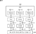
例えば、「Cell」の技術を採用したコンピュータにおいて、図14に示されるように、PU141−1乃至SPU141−3において単一のOS143が稼動しており、OS143の中で、プロセス151−1乃至151−3が稼動している場合も考えられる。
For example, in a computer adopting the “Cell” technology, as shown in FIG. 14, a
図14に示されるような場合であっても、プロセス151−1乃至151−3に対してそれぞれ異なるIPアドレス、MACアドレス、またはVLANIDが付与されていれば、本発明を適用することが可能である。この場合、PU142−1乃至SPU142−3からそれぞれのプロセッサで処理するプロセスに付与されたIPアドレス、MACアドレス、またはVLANIDと、それぞれのプロセッサに対応して設けられたSNRのIDに関する情報をテーブル管理部204に供給し、図7、図10、または図12に示されるようなテーブルを生成または更新するようにすればよい。 Even in the case shown in FIG. 14, the present invention can be applied if different IP addresses, MAC addresses, or VLAN IDs are assigned to the processes 151-1 to 151-3. is there. In this case, table management is performed on information regarding IP addresses, MAC addresses, or VLAN IDs assigned to processes processed by the respective processors from the PU 142-1 to SPU 142-3, and IDs of SNRs provided for the respective processors. The table may be supplied to the unit 204 to generate or update a table as shown in FIG. 7, FIG. 10, or FIG.
なお、上述した一連の処理は、ハードウェアにより実行させることもできるし、ソフトウェアにより実行させることもできる。すなわち、上述したネットワークインタフェースカードを情報処理装置として構成し、その情報処理装置にインストールされたソフトウェアにより上述した一連の処理を実行させるようにすることも可能である。上述した一連の処理をソフトウェアにより実行させる場合には、そのソフトウェアを構成するプログラムが、インターネットなどのネットワークや、リムーバブルメディアなどからなる記録媒体からインストールされる。 The series of processes described above can be executed by hardware, or can be executed by software. That is, the above-described network interface card can be configured as an information processing apparatus, and the above-described series of processing can be executed by software installed in the information processing apparatus. When the above-described series of processing is executed by software, a program constituting the software is installed from a network such as the Internet or a recording medium such as a removable medium.
本明細書において上述した一連の処理を実行するステップは、記載された順序に沿って時系列的に行われる処理はもちろん、必ずしも時系列的に処理されなくとも、並列的あるいは個別に実行される処理をも含むものである。 The steps of executing the series of processes described above in this specification are performed in parallel or individually even if they are not necessarily processed in time series, as well as processes performed in time series in the order described. It also includes processing.
101 ネットワークインタフェースカード, 102 ネットワーク, 141−1乃至141−3 SNR, 142−1 PU, 142−2 SPU, 142−3 SPU, 143−1乃至143−3 OS, 151−1乃至151−3 プロセス, 201 受信部, 202 アドレス解析部, 203 割り込み発生部, 204 テーブル管理部 101 network interface card, 102 network, 141-1 to 141-3 SNR, 142-1 PU, 142-2 SPU, 142-3 SPU, 143-1 to 143-3 OS, 151-1 to 151-3 process, 201 reception unit, 202 address analysis unit, 203 interrupt generation unit, 204 table management unit
Claims (8)
前記ネットワークから所定の単位のデータを受信する受信手段と、
前記受信手段により受信されたデータに付加された識別データを解析する解析手段と、
前記識別データと、前記OSを実行するプロセッサの割り込みレジスタを特定する情報とを対応付けたテーブルを保持する保持手段と、
前記保持手段に保持されるテーブルに基づいて特定される前記解析手段により解析された前記識別データに対応する前記割り込みレジスタに、前記受信手段により受信されたデータを書き込むことで、前記プロセッサに対する割り込み処理を発生させる発生手段と
を備える情報処理装置。 An information processing apparatus that processes data received via a network by each individual OS (Operating System) executed by a plurality of processors,
Receiving means for receiving a predetermined unit of data from the network;
Analyzing means for analyzing identification data added to the data received by the receiving means;
Holding means for holding a table in which the identification data is associated with information specifying an interrupt register of a processor that executes the OS;
Interrupt processing for the processor by writing the data received by the receiving means to the interrupt register corresponding to the identification data analyzed by the analyzing means specified based on the table held by the holding means An information processing apparatus comprising: generating means for generating
請求項1に記載の情報処理装置。 The information processing apparatus according to claim 1, wherein the data received by the receiving unit is an IP packet, and the identification information is a destination IP address of the IP packet.
請求項1に記載の情報処理装置。 The information processing apparatus according to claim 1, wherein the data received by the receiving unit is a data link layer frame, and the identification information is a destination MAC address of the frame.
請求項1に記載の情報処理装置。 The information processing apparatus according to claim 1, wherein the Ethernet (registered trademark) frame is a frame conforming to IEEE 802.1Q, and the identification information is a VLAN ID included in a tag of the frame.
前記保持手段は、前記識別データと、前記プロセスを実行するプロセッサの割り込みレジスタを特定する情報とを対応付けたテーブルを保持する
請求項1に記載の情報処理装置。 The plurality of processors execute respective individual processes executed by a single OS,
The information processing apparatus according to claim 1, wherein the holding unit holds a table in which the identification data is associated with information for specifying an interrupt register of a processor that executes the process.
前記ネットワークから所定の単位のデータを受信し、
前記受信されたデータに付加された識別データを解析し、
前記識別データと、前記OSを実行するプロセッサの割り込みレジスタを特定する情報とを対応付けたテーブルに基づいて、前記解析された前記識別データに対応する前記割り込みレジスタを特定し、
特定された前記割り込みレジスタに、前記受信されたデータを書き込むことで、前記プロセッサに対する割り込み処理を発生させるステップ
を含む情報処理方法。 An information processing method of an information processing apparatus for processing data received via a network by each individual OS (Operating System) executed by a plurality of processors,
Receiving a predetermined unit of data from the network;
Analyzing the identification data added to the received data;
Identifying the interrupt register corresponding to the analyzed identification data based on a table associating the identification data with information identifying the interrupt register of the processor executing the OS,
An information processing method comprising: generating an interrupt process for the processor by writing the received data to the identified interrupt register.
前記ネットワークから所定の単位のデータの受信を制御し、
前記受信されたデータに付加された識別データの解析を制御し、
前記識別データと、前記OSを実行するプロセッサの割り込みレジスタを特定する情報とを対応付けたテーブルに基づいて、前記解析された前記識別データに対応する前記割り込みレジスタの特定を制御し、
特定された前記割り込みレジスタに、前記受信されたデータを書き込むことで、前記プロセッサに対する割り込み処理の発生を制御するステップ
を含むコンピュータが読み取り可能なプログラム。 A program for causing an information processing apparatus to process data received via a network by each individual OS (Operating System) executed by a plurality of processors,
Control reception of a predetermined unit of data from the network;
Controlling analysis of identification data added to the received data;
Based on a table in which the identification data is associated with information for identifying an interrupt register of a processor that executes the OS, the identification of the interrupt register corresponding to the analyzed identification data is controlled,
A computer-readable program including the step of controlling generation of interrupt processing for the processor by writing the received data to the specified interrupt register.
Priority Applications (2)
| Application Number | Priority Date | Filing Date | Title |
|---|---|---|---|
| JP2006024647A JP2007206955A (en) | 2006-02-01 | 2006-02-01 | Apparatus and method for information processing, program, and recording medium |
| US11/669,766 US7783810B2 (en) | 2006-02-01 | 2007-01-31 | Apparatus and method of processing information |
Applications Claiming Priority (1)
| Application Number | Priority Date | Filing Date | Title |
|---|---|---|---|
| JP2006024647A JP2007206955A (en) | 2006-02-01 | 2006-02-01 | Apparatus and method for information processing, program, and recording medium |
Publications (2)
| Publication Number | Publication Date |
|---|---|
| JP2007206955A true JP2007206955A (en) | 2007-08-16 |
| JP2007206955A5 JP2007206955A5 (en) | 2009-03-26 |
Family
ID=38445374
Family Applications (1)
| Application Number | Title | Priority Date | Filing Date |
|---|---|---|---|
| JP2006024647A Pending JP2007206955A (en) | 2006-02-01 | 2006-02-01 | Apparatus and method for information processing, program, and recording medium |
Country Status (2)
| Country | Link |
|---|---|
| US (1) | US7783810B2 (en) |
| JP (1) | JP2007206955A (en) |
Cited By (3)
| Publication number | Priority date | Publication date | Assignee | Title |
|---|---|---|---|---|
| EP2161660A2 (en) | 2008-09-09 | 2010-03-10 | Fujitsu Limited | Information processing device having load sharing function |
| US8645668B2 (en) | 2007-01-11 | 2014-02-04 | Sony Corporation | Information processing apparatus, information processing method and computer program |
| JP2014038438A (en) * | 2012-08-14 | 2014-02-27 | Fujitsu Ltd | Arithmetic processing unit, information processing apparatus and interruption control method |
Families Citing this family (3)
| Publication number | Priority date | Publication date | Assignee | Title |
|---|---|---|---|---|
| KR101475640B1 (en) * | 2010-10-22 | 2014-12-22 | 미쓰비시덴키 가부시키가이샤 | Interrupt signal accepting device and computer device |
| JP5933356B2 (en) * | 2012-06-12 | 2016-06-08 | ルネサスエレクトロニクス株式会社 | Computer system |
| US9628333B2 (en) * | 2013-12-04 | 2017-04-18 | International Business Machines Corporation | Operating a dual chipset network interface controller (‘NIC’) that includes a high performance media access control chipset and a low performance media access control chipset |
Citations (4)
| Publication number | Priority date | Publication date | Assignee | Title |
|---|---|---|---|---|
| JPS6159565A (en) * | 1984-08-31 | 1986-03-27 | Hitachi Ltd | Interrupt input device of multicomputer system |
| JPH05298264A (en) * | 1992-04-22 | 1993-11-12 | Toshiba Corp | Computer system |
| JP2002342299A (en) * | 2001-05-18 | 2002-11-29 | Nec Corp | Cluster system, computer and program |
| JP2005316629A (en) * | 2004-04-28 | 2005-11-10 | Hitachi Ltd | Network protocol processing device |
Family Cites Families (11)
| Publication number | Priority date | Publication date | Assignee | Title |
|---|---|---|---|---|
| US6389468B1 (en) * | 1999-03-01 | 2002-05-14 | Sun Microsystems, Inc. | Method and apparatus for distributing network traffic processing on a multiprocessor computer |
| US6467008B1 (en) * | 1999-03-01 | 2002-10-15 | Sun Microsystems, Inc. | Method and apparatus for indicating an interrupt in a network interface |
| US6631422B1 (en) * | 1999-08-26 | 2003-10-07 | International Business Machines Corporation | Network adapter utilizing a hashing function for distributing packets to multiple processors for parallel processing |
| US7126952B2 (en) * | 2001-09-28 | 2006-10-24 | Intel Corporation | Multiprotocol decapsulation/encapsulation control structure and packet protocol conversion method |
| US7177943B1 (en) * | 2001-12-27 | 2007-02-13 | Cisco Technology, Inc. | System and method for processing packets in a multi-processor environment |
| US7529242B1 (en) * | 2002-02-15 | 2009-05-05 | Symantec Corporation | Routing network packets for multi-processor network flow analysis |
| JP2004252776A (en) | 2003-02-20 | 2004-09-09 | Ntt Data Corp | Control method of multi-operating system, program making computer execute same method, and control device of multi-operating system |
| US7418505B2 (en) * | 2003-05-26 | 2008-08-26 | Ewha University Industry Collaboration Foundation | IP address lookup using either a hashing table or multiple hash functions |
| US20050125582A1 (en) * | 2003-12-08 | 2005-06-09 | Tu Steven J. | Methods and apparatus to dispatch interrupts in multi-processor systems |
| US7103693B2 (en) * | 2004-09-30 | 2006-09-05 | International Business Machines Corporation | Method for applying interrupt coalescing to incoming messages based on message length |
| EP1734418A1 (en) * | 2005-06-15 | 2006-12-20 | Manufacture Roger Dubuis S.A. | Timepiece |
-
2006
- 2006-02-01 JP JP2006024647A patent/JP2007206955A/en active Pending
-
2007
- 2007-01-31 US US11/669,766 patent/US7783810B2/en not_active Expired - Fee Related
Patent Citations (4)
| Publication number | Priority date | Publication date | Assignee | Title |
|---|---|---|---|---|
| JPS6159565A (en) * | 1984-08-31 | 1986-03-27 | Hitachi Ltd | Interrupt input device of multicomputer system |
| JPH05298264A (en) * | 1992-04-22 | 1993-11-12 | Toshiba Corp | Computer system |
| JP2002342299A (en) * | 2001-05-18 | 2002-11-29 | Nec Corp | Cluster system, computer and program |
| JP2005316629A (en) * | 2004-04-28 | 2005-11-10 | Hitachi Ltd | Network protocol processing device |
Cited By (3)
| Publication number | Priority date | Publication date | Assignee | Title |
|---|---|---|---|---|
| US8645668B2 (en) | 2007-01-11 | 2014-02-04 | Sony Corporation | Information processing apparatus, information processing method and computer program |
| EP2161660A2 (en) | 2008-09-09 | 2010-03-10 | Fujitsu Limited | Information processing device having load sharing function |
| JP2014038438A (en) * | 2012-08-14 | 2014-02-27 | Fujitsu Ltd | Arithmetic processing unit, information processing apparatus and interruption control method |
Also Published As
| Publication number | Publication date |
|---|---|
| US20070204084A1 (en) | 2007-08-30 |
| US7783810B2 (en) | 2010-08-24 |
Similar Documents
| Publication | Publication Date | Title |
|---|---|---|
| US10678583B2 (en) | Guest controlled virtual device packet filtering | |
| CA2852471C (en) | Method and system for supporting wake-on-lan in a virtualized environment | |
| US20220052943A1 (en) | Methods and apparatus to configure and manage network resources for use in network-based computing | |
| US8949498B2 (en) | Interrupt handling in a virtual machine environment | |
| US7865782B2 (en) | I/O device fault processing method for use in virtual computer system | |
| US8886862B2 (en) | Virtualization of interrupts | |
| US20150100970A1 (en) | Application-driven shared device queue polling | |
| US10409744B1 (en) | Low-latency wake-up in a peripheral device | |
| JP2006099331A5 (en) | ||
| JP2007206955A (en) | Apparatus and method for information processing, program, and recording medium | |
| US20230029932A1 (en) | Server delay control device, server delay control method, and program | |
| JP2013508833A (en) | Apparatus, method, and computer program for efficient communication between partitions in a logically partitioned system | |
| US10353857B2 (en) | Parallel processing apparatus and method for controlling communication | |
| US10044813B2 (en) | Failover and live migration of zero/thin clients | |
| US20110282987A1 (en) | Communication method, system, and program | |
| US20220342769A1 (en) | Application consistent network backup using three phase full quorum | |
| US10162675B2 (en) | Parallel processing system | |
| JP5854130B2 (en) | Information processing apparatus, information processing method, and program | |
| US20240129255A1 (en) | Server delay control device, server delay control method, and program | |
| EP4310680A1 (en) | Intra-server delay control device, intra-server delay control method, and program | |
| JP4432975B2 (en) | Packet communication device, packet communication method, and packet communication program | |
| WO2022172366A1 (en) | Intra-server delay control device, intra-server delay control method, and program | |
| JP6582785B2 (en) | Virtual machine management system, virtual machine management method and program | |
| JP2014078099A (en) | Virtual computer system and control method therefor | |
| JP2017174327A (en) | Information processing device, power saving control method, and power saving control program |
Legal Events
| Date | Code | Title | Description |
|---|---|---|---|
| A521 | Request for written amendment filed |
Free format text: JAPANESE INTERMEDIATE CODE: A523 Effective date: 20090129 |
|
| A621 | Written request for application examination |
Free format text: JAPANESE INTERMEDIATE CODE: A621 Effective date: 20090129 |
|
| RD02 | Notification of acceptance of power of attorney |
Free format text: JAPANESE INTERMEDIATE CODE: A7422 Effective date: 20090205 |
|
| A977 | Report on retrieval |
Free format text: JAPANESE INTERMEDIATE CODE: A971007 Effective date: 20100621 |
|
| A131 | Notification of reasons for refusal |
Free format text: JAPANESE INTERMEDIATE CODE: A131 Effective date: 20100624 |
|
| A521 | Request for written amendment filed |
Free format text: JAPANESE INTERMEDIATE CODE: A523 Effective date: 20100811 |
|
| A711 | Notification of change in applicant |
Free format text: JAPANESE INTERMEDIATE CODE: A712 Effective date: 20101126 |
|
| A02 | Decision of refusal |
Free format text: JAPANESE INTERMEDIATE CODE: A02 Effective date: 20110111 |