JP2007200575A - Multi-pole connector and portable wireless terminal or small-sized electronic apparatus using same - Google Patents
Multi-pole connector and portable wireless terminal or small-sized electronic apparatus using same Download PDFInfo
- Publication number
- JP2007200575A JP2007200575A JP2006014349A JP2006014349A JP2007200575A JP 2007200575 A JP2007200575 A JP 2007200575A JP 2006014349 A JP2006014349 A JP 2006014349A JP 2006014349 A JP2006014349 A JP 2006014349A JP 2007200575 A JP2007200575 A JP 2007200575A
- Authority
- JP
- Japan
- Prior art keywords
- contact
- receptacle
- contacts
- meandering curved
- curved portion
- Prior art date
- Legal status (The legal status is an assumption and is not a legal conclusion. Google has not performed a legal analysis and makes no representation as to the accuracy of the status listed.)
- Granted
Links
- 230000005405 multipole Effects 0.000 title claims description 8
- 239000000758 substrate Substances 0.000 claims description 19
- 238000000465 moulding Methods 0.000 claims description 5
- 230000005489 elastic deformation Effects 0.000 claims description 2
- 230000005540 biological transmission Effects 0.000 abstract description 9
- 238000003780 insertion Methods 0.000 description 10
- 230000037431 insertion Effects 0.000 description 10
- 238000000034 method Methods 0.000 description 6
- 230000008054 signal transmission Effects 0.000 description 5
- 238000005476 soldering Methods 0.000 description 5
- 239000011347 resin Substances 0.000 description 3
- 229920005989 resin Polymers 0.000 description 3
- WYTGDNHDOZPMIW-RCBQFDQVSA-N alstonine Natural products C1=CC2=C3C=CC=CC3=NC2=C2N1C[C@H]1[C@H](C)OC=C(C(=O)OC)[C@H]1C2 WYTGDNHDOZPMIW-RCBQFDQVSA-N 0.000 description 2
- 239000004973 liquid crystal related substance Substances 0.000 description 2
- 229910000679 solder Inorganic materials 0.000 description 2
- RYGMFSIKBFXOCR-UHFFFAOYSA-N Copper Chemical compound [Cu] RYGMFSIKBFXOCR-UHFFFAOYSA-N 0.000 description 1
- XAGFODPZIPBFFR-UHFFFAOYSA-N aluminium Chemical compound [Al] XAGFODPZIPBFFR-UHFFFAOYSA-N 0.000 description 1
- 229910052782 aluminium Inorganic materials 0.000 description 1
- 238000013459 approach Methods 0.000 description 1
- 239000004020 conductor Substances 0.000 description 1
- 229910052802 copper Inorganic materials 0.000 description 1
- 239000010949 copper Substances 0.000 description 1
- 230000006866 deterioration Effects 0.000 description 1
- 230000000694 effects Effects 0.000 description 1
- 230000000149 penetrating effect Effects 0.000 description 1
Images


Classifications
-
- H—ELECTRICITY
- H01—ELECTRIC ELEMENTS
- H01R—ELECTRICALLY-CONDUCTIVE CONNECTIONS; STRUCTURAL ASSOCIATIONS OF A PLURALITY OF MUTUALLY-INSULATED ELECTRICAL CONNECTING ELEMENTS; COUPLING DEVICES; CURRENT COLLECTORS
- H01R24/00—Two-part coupling devices, or either of their cooperating parts, characterised by their overall structure
- H01R24/28—Coupling parts carrying pins, blades or analogous contacts and secured only to wire or cable
- H01R24/30—Coupling parts carrying pins, blades or analogous contacts and secured only to wire or cable with additional earth or shield contacts
-
- H—ELECTRICITY
- H01—ELECTRIC ELEMENTS
- H01R—ELECTRICALLY-CONDUCTIVE CONNECTIONS; STRUCTURAL ASSOCIATIONS OF A PLURALITY OF MUTUALLY-INSULATED ELECTRICAL CONNECTING ELEMENTS; COUPLING DEVICES; CURRENT COLLECTORS
- H01R12/00—Structural associations of a plurality of mutually-insulated electrical connecting elements, specially adapted for printed circuits, e.g. printed circuit boards [PCB], flat or ribbon cables, or like generally planar structures, e.g. terminal strips, terminal blocks; Coupling devices specially adapted for printed circuits, flat or ribbon cables, or like generally planar structures; Terminals specially adapted for contact with, or insertion into, printed circuits, flat or ribbon cables, or like generally planar structures
- H01R12/70—Coupling devices
- H01R12/71—Coupling devices for rigid printing circuits or like structures
- H01R12/712—Coupling devices for rigid printing circuits or like structures co-operating with the surface of the printed circuit or with a coupling device exclusively provided on the surface of the printed circuit
- H01R12/716—Coupling device provided on the PCB
-
- H—ELECTRICITY
- H01—ELECTRIC ELEMENTS
- H01R—ELECTRICALLY-CONDUCTIVE CONNECTIONS; STRUCTURAL ASSOCIATIONS OF A PLURALITY OF MUTUALLY-INSULATED ELECTRICAL CONNECTING ELEMENTS; COUPLING DEVICES; CURRENT COLLECTORS
- H01R12/00—Structural associations of a plurality of mutually-insulated electrical connecting elements, specially adapted for printed circuits, e.g. printed circuit boards [PCB], flat or ribbon cables, or like generally planar structures, e.g. terminal strips, terminal blocks; Coupling devices specially adapted for printed circuits, flat or ribbon cables, or like generally planar structures; Terminals specially adapted for contact with, or insertion into, printed circuits, flat or ribbon cables, or like generally planar structures
- H01R12/70—Coupling devices
- H01R12/77—Coupling devices for flexible printed circuits, flat or ribbon cables or like structures
- H01R12/79—Coupling devices for flexible printed circuits, flat or ribbon cables or like structures connecting to rigid printed circuits or like structures
-
- H—ELECTRICITY
- H01—ELECTRIC ELEMENTS
- H01R—ELECTRICALLY-CONDUCTIVE CONNECTIONS; STRUCTURAL ASSOCIATIONS OF A PLURALITY OF MUTUALLY-INSULATED ELECTRICAL CONNECTING ELEMENTS; COUPLING DEVICES; CURRENT COLLECTORS
- H01R13/00—Details of coupling devices of the kinds covered by groups H01R12/70 or H01R24/00 - H01R33/00
- H01R13/648—Protective earth or shield arrangements on coupling devices, e.g. anti-static shielding
- H01R13/658—High frequency shielding arrangements, e.g. against EMI [Electro-Magnetic Interference] or EMP [Electro-Magnetic Pulse]
-
- Y—GENERAL TAGGING OF NEW TECHNOLOGICAL DEVELOPMENTS; GENERAL TAGGING OF CROSS-SECTIONAL TECHNOLOGIES SPANNING OVER SEVERAL SECTIONS OF THE IPC; TECHNICAL SUBJECTS COVERED BY FORMER USPC CROSS-REFERENCE ART COLLECTIONS [XRACs] AND DIGESTS
- Y10—TECHNICAL SUBJECTS COVERED BY FORMER USPC
- Y10S—TECHNICAL SUBJECTS COVERED BY FORMER USPC CROSS-REFERENCE ART COLLECTIONS [XRACs] AND DIGESTS
- Y10S439/00—Electrical connectors
- Y10S439/941—Crosstalk suppression
Abstract
Description
本発明は、携帯電話に代表される携帯型無線端末やノート型パソコンに代表される小型電子機器等に使用されるコネクタ、より詳しくは、横長のボディの長手方向に複数のコンタクトが所定間隔で組み込まれた多極コネクタ及び多極コネクタを使用した携帯型無線端末又は小型電子機器に関する。 The present invention relates to a connector used in a portable wireless terminal typified by a mobile phone or a small electronic device typified by a notebook computer, and more specifically, a plurality of contacts are arranged at predetermined intervals in the longitudinal direction of a horizontally long body. The present invention relates to a built-in multipolar connector and a portable wireless terminal or small electronic device using the multipolar connector.
携帯電話やノート型パソコンにおいては、液晶表示装置等に接続されたケーブルをマザーボード上の基板に接続するために、多極基板実装型のコネクタが使用されている。この型式のコネクタは、例えば特許文献1〜3に記載されているように、複数本のケーブルがアッセンブリされる横長のコネクタプラグと、これが嵌合する横長の基板実装型レセプタクルとの組合せからなる。 In mobile phones and notebook computers, multi-pole board mounting connectors are used to connect cables connected to a liquid crystal display device or the like to a board on a motherboard. This type of connector comprises, for example, a combination of a horizontally long connector plug into which a plurality of cables are assembled and a horizontally long board-mounted receptacle to which the cable is fitted, as described in Patent Documents 1 to 3, for example.
横長のコネクタプラグは通常、横長のレセプタクルに被さるキャップ型式になっており、長手方向(横幅方向)に所定間隔で配列された多数個のプラグコンタクトを有している。多数個のプラグコンタクトは、アッセンブリされた多数本のケーブルと電気的に接続されている。一方、レセプタクルは、多数個のプラグコンタクトに対応するように長手方向(横幅方向)に所定間隔で配列された多数個のレセプタクルコンタクトを有している。多数個のレセプタクルコンタクトは、横長の樹脂ボディの長手方向に所定間隔で形成された長手方向に直角なスリット状の挿入部に挿入されており、各レセプタクルコンタクトの一端部は対応するプラグコンタクトに圧接する接点部である。また、他端部は基板実装部であり、基板表面に形成された配線パターンに半田付けなどにより接合される。 The horizontally long connector plug is usually of a cap type covering a horizontally long receptacle, and has a large number of plug contacts arranged at predetermined intervals in the longitudinal direction (lateral width direction). The multiple plug contacts are electrically connected to the assembled multiple cables. On the other hand, the receptacle has a large number of receptacle contacts arranged at predetermined intervals in the longitudinal direction (lateral width direction) so as to correspond to the large number of plug contacts. A large number of receptacle contacts are inserted into slit-shaped insertion portions perpendicular to the longitudinal direction formed at predetermined intervals in the longitudinal direction of the horizontally long resin body, and one end of each receptacle contact is pressed against the corresponding plug contact. It is a contact part. The other end is a board mounting part, and is joined to a wiring pattern formed on the board surface by soldering or the like.
そして通常は、プラグコンタクトとの弾性接触を確実とするために、接点部と基板実装部との間に、弾性変形部としての蛇行湾曲部が設けられている。 In general, a meandering curved portion as an elastically deforming portion is provided between the contact portion and the substrate mounting portion in order to ensure elastic contact with the plug contact.
基板表面に実装されたレセプタクルにコネクタプラグを装着することにより、レセプタクル内の多数個のレセプタクルコンタクトの各蛇行湾曲部などが弾性変形し、その復元力により、多数個のレセプタクルコンタクトがコネクタプラグ内の対応するプラグコンタクトに圧接する。これにより、コネクタプラグにアッセンブリされた多数本のケーブルが、基板表面に形成された配線パターンに電気的に接続される。 By attaching the connector plug to the receptacle mounted on the surface of the board, the meandering curved portions of the multiple receptacle contacts in the receptacle are elastically deformed, and the restoring force causes the multiple receptacle contacts to be in the connector plug. Press contact the corresponding plug contact. Thereby, a large number of cables assembled in the connector plug are electrically connected to the wiring pattern formed on the surface of the substrate.
このような多極基板実装型のコネクタにおいては、レセプタクルの基板との接合強度の確保やシールドなどを目的として、レセプタクルボディの両端部、即ちレセプタクルコンタクト群の両側に、実装端子を兼ねるグランド端子が設けられる。しかしながら、両端のグランド端子の間に多数個のレセプタクルコンタクトが配置されるために、レセプタクルコンタクトの配置位置によって、コンタクトからグランド端子までの距離に差が生じる。すなわち、ボディの両端部に配置されたコンタクトはグランド端子に近く、両端部から離れて中央部に近づくほどグランド端子までの距離は増大する。その結果、コンタクト間でインピーダンス特性に差が生じ、次のような問題を発生させることになる。 In such a multi-pole board-mounted connector, ground terminals that also serve as mounting terminals are provided at both ends of the receptacle body, that is, both sides of the receptacle contact group, for the purpose of ensuring the bonding strength of the receptacle and the shield, etc. Provided. However, since a large number of receptacle contacts are arranged between the ground terminals at both ends, the distance from the contact to the ground terminal varies depending on the arrangement position of the receptacle contacts. That is, the contacts disposed at both ends of the body are close to the ground terminal, and the distance to the ground terminal increases as the distance from the both ends approaches the center. As a result, a difference in impedance characteristics occurs between the contacts, causing the following problems.
高速デジタル信号処理のために、コネクタ通過域でのインピーダンス特性の整合が求められるが、差動伝送を行う場合、2本のライン間のスキュー(電気的な長さの差)が大きくなると、差動伝送路の伝送特性が低下する。また、複数の差動ラインにより電気信号を伝送する場合、差動ペア間でスキューが大きくなると、受信側での処理にエラーが多くなる危険がある。前述した従来構造の場合、コンタクト間でインピーダンス特性に差が生じるために、スキューが大きくなり、差動ペア間のスキューも大きくなる。その結果、前述した伝送特性の低下や受信側でのエラー増加といった問題が発生する。 For high-speed digital signal processing, matching of impedance characteristics in the connector passband is required. However, when differential transmission is performed, if the skew (difference in electrical length) between two lines increases, The transmission characteristics of the dynamic transmission line deteriorate. Further, when an electrical signal is transmitted through a plurality of differential lines, there is a risk that errors in processing on the receiving side increase if the skew between the differential pairs increases. In the case of the above-described conventional structure, a difference occurs in the impedance characteristics between the contacts, so that the skew increases and the skew between the differential pairs also increases. As a result, problems such as the aforementioned deterioration of transmission characteristics and an increase in errors on the receiving side occur.
この問題を解決するために、従来は差動ペア用の2極の両側にあるコンタクトをグランド端子に使用して両極間でインピーダンス特性の整合を図っているが、必要なコンタクト数が増加し、部品点数が増加するだけでなく、コネクタが長手方向(コンタクト配列方向)で大型化する。 In order to solve this problem, the contacts on both sides of the two poles for the differential pair are conventionally used as ground terminals to match the impedance characteristics between the two poles, but the number of required contacts increases, Not only does the number of components increase, but the size of the connector increases in the longitudinal direction (contact arrangement direction).
これに加えて、高速デジタル信号処理では、基板配線、ケーブル配線及びコネクタ配線は、単なる接続線ではなく、信号伝送路と考えること必要であり、信号伝送路とグランドとの位置関係を一定にする配慮が必要となる。すなわち、コンタクト配列方向だけでなく、コンタクト配列方向に直角な方向においても、コンタクトとグランドとの位置関係を一定に保ち、インピーダンス特性を均一化することが必要である。 In addition to this, in high-speed digital signal processing, board wiring, cable wiring, and connector wiring need to be considered as signal transmission paths, not simple connection lines, and the positional relationship between the signal transmission path and the ground is made constant. Consideration is required. That is, it is necessary to maintain the positional relationship between the contact and the ground constant and make the impedance characteristics uniform not only in the contact arrangement direction but also in a direction perpendicular to the contact arrangement direction.
しかしながら、従来の基板実装型レセプタクルにおいては、前述したとおり、プラグ側の対応するコンタクトとの弾性接触を確実ならしめるために、レセプタクルコンタクトの中間部に蛇行湾曲部が設けられていることが多い。その結果、この蛇行湾曲部でグランドとの位置関係が大きく変化し、これによってもインピーダンス特性の不整合に起因する問題が生じる。 However, in the conventional board-mounted receptacle, as described above, a meandering curved portion is often provided at the intermediate portion of the receptacle contact in order to ensure elastic contact with the corresponding contact on the plug side. As a result, the positional relationship with the ground changes greatly at the meandering curved portion, and this also causes a problem due to impedance mismatching.
本発明はかかる事情に鑑みて創案されたものであり、コンタクト数が多い場合にもコンタクト配列方向でインピーダンス特性の整合を図ることができる多極コネクタ及び多極コネクタを使用した携帯型無線端末又は小型電子機器を提供することを目的とする。 The present invention was devised in view of such circumstances, and a multi-pole connector capable of matching impedance characteristics in the contact arrangement direction even when the number of contacts is large, and a portable wireless terminal using the multi-pole connector or An object is to provide a small electronic device.
本発明の別の目的は、コンタクト中間部に弾性変形部としての蛇行湾曲部を有するにもかかわらず、この部分でコンタクトとグランドの間の位置関係を可及的に一定に保ち、コンタクト配列方向に直角な方向でインピーダンス特性の整合を図ることができる多極コネクタを提供することにある。 Another object of the present invention is to maintain the positional relationship between the contact and the ground as constant as possible in this portion, despite having a meandering curved portion as an elastically deforming portion in the middle portion of the contact. It is an object of the present invention to provide a multipolar connector capable of matching impedance characteristics in a direction perpendicular to the direction.
上記目的を達成するために、本発明に係る多極コネクタは、横長のボディの長手方向に複数のコンタクトが所定間隔で組み込まれており、各コンタクトが、対応するコンタクトとの弾性接触のための弾性変形部として蛇行湾曲部を中間部に有する多極コネクタにおいて、複数のコンタクトの各蛇行湾曲部の内側を通って前記ボディの長手方向に延在するアース部材を具備している。 In order to achieve the above object, in the multipolar connector according to the present invention, a plurality of contacts are incorporated at predetermined intervals in the longitudinal direction of the horizontally long body, and each contact is for elastic contact with the corresponding contact. The multipolar connector having a meandering curved portion as an elastic deformation portion in the middle portion includes an earth member extending in the longitudinal direction of the body through the inside of each meandering curved portion of the plurality of contacts.
本発明に係る多極コネクタにおいては、複数のコンタクトの各蛇行湾曲部の内側を通ってボディの長手方向に延在するアース部材が設けられていることにより、コンタクト配列方向において、複数のコンタクトとグランドとの位置関係が一定になり、コンタクト間でインピーダンス特性の整合が図られる。また、複数のコンタクトの各蛇行湾曲部で、コンタクトとグランドの位置関係が均等化され、コンタクト配列方向に直角な方向でもインピーダンス特性の整合が図られる。 In the multipolar connector according to the present invention, by providing a grounding member extending in the longitudinal direction of the body through the inside of each meandering curved portion of the plurality of contacts, in the contact arrangement direction, a plurality of contacts and The positional relationship with the ground becomes constant, and impedance characteristics are matched between the contacts. Further, the positional relationship between the contact and the ground is equalized at each meandering curved portion of the plurality of contacts, and impedance characteristics are matched even in a direction perpendicular to the contact arrangement direction.
このアース部材は、各コンタクトにおける蛇行湾曲部に対して同じ位置関係であることが、コンタクト間でのインピーダンス整合性を高める点から望ましい。また、蛇行湾曲部でのコンタクトとグランドの位置関係の均等化を図る点から、各コンタクトにおける蛇行湾曲部の内側のほぼ中央部に存在させるのが好ましく、具体的には、各コンタクトにおける蛇行湾曲部が、3つの直線部をほぼ直角に繋いだ略コ字状である場合は、アース部材は、それら3つの直線部からほぼ当距離の位置に存在させるのが好ましい。 It is desirable that the ground member has the same positional relationship with respect to the meandering curved portion in each contact from the viewpoint of improving impedance matching between the contacts. Further, from the viewpoint of equalizing the positional relationship between the contact and the ground in the meandering curved portion, it is preferable to be present at the substantially central portion inside the meandering curved portion in each contact. Specifically, the meandering curvature in each contact In the case where the portion has a substantially U-shape that connects the three straight portions at a substantially right angle, it is preferable that the grounding member be present at a position that is substantially the same distance from the three straight portions.
アース部材は又、ボディ中にインサート成形により組み込むのが好ましい。これにより、ボディに溝等を設ける必要がなくなり、ボディの強度低下による反りの防止等が可能になる。また、アース部材とコンタクトとを接近させるための薄肉化も可能となり、アース部材の配置位置に関する自由度が大きくなる。 The ground member is also preferably incorporated into the body by insert molding. As a result, it is not necessary to provide a groove or the like in the body, and it becomes possible to prevent warping due to a decrease in the strength of the body. Further, it is possible to reduce the thickness of the ground member and the contact so that the degree of freedom with respect to the position of the ground member is increased.
本発明に係る多極コネクタは、基板実装型として好適であり、特にコネクタプラグと組み合わされるレセプタクルにその構造は好適である。 The multipolar connector according to the present invention is suitable as a board mounting type, and the structure is particularly suitable for a receptacle combined with a connector plug.
本発明に係る多極コネクタにおいては、コンタクトの蛇行湾曲部についてインピーダンス特性の整合を図ることを主眼とするが、蛇行湾曲部は通常コンタクトの一端部に形成された接点部と他端部に形成された基板実装部との間の中間部分に形成されており、前記中間部分における蛇行湾曲部以外の部分の少なくとも一部についても、下方の基板までの距離が前記蛇行湾曲部から前記アース部材までの距離にほぼ等しくなるように構成するのが好ましい。これにより、コンタクト配列方向に直角な方向におけるインピーダンス特性の整合性が更に向上する。 In the multipolar connector according to the present invention, the main purpose is to match the impedance characteristics of the meandering curved portion of the contact, but the meandering curved portion is usually formed at one end of the contact and the other end. Formed at an intermediate portion between the board mounting portion and at least a part of the intermediate portion other than the meandering curved portion, the distance to the lower substrate is also from the meandering curved portion to the ground member. It is preferable that the distance is approximately equal to the distance. This further improves the consistency of impedance characteristics in the direction perpendicular to the contact arrangement direction.
また、レセプタクルとコネクタプラグが組み合わされる多極コネクタの場合、コネクタプラグは、複数個のレセプタクルコンタクトに対応するプラグコンタクトをボディに装備すると共に、前記ボディを覆うシールド部材を装備しており、各プラグコンタクトは、レセプタクルコンタクトと接触する第1接点部を一端部に有すると共に、他端部にケーブルと接続される第2接点部を有するのが通例である。 In the case of a multipolar connector in which a receptacle and a connector plug are combined, the connector plug is equipped with plug contacts corresponding to a plurality of receptacle contacts on the body, and a shield member covering the body. The contact typically has a first contact portion in contact with the receptacle contact at one end and a second contact portion connected to the cable at the other end.
そして、各プラグコンタクトについてもインピーダンス対策を施すのが好ましく、具体的には、第1接点部及び第2接点部からシールド部材までの各距離が、レセプタクルコンタクトにおける蛇行湾曲部から前記アース部材までの距離にほぼ等しくなるように構成するのが好ましく、第1接点部と第2接点部を繋ぐ部分の少なくとも一部が、前記シールド部材までの距離がレセプタクルコンタクトにおける蛇行湾曲部から前記アース部材までの距離にほぼ等しくなるように構成するのが更に好ましい。これにより、コンタクト配列方向に直角な方向におけるインピーダンス特性の整合性が更に向上する。 In addition, it is preferable to take measures against impedance for each plug contact. Specifically, each distance from the first contact portion and the second contact portion to the shield member is from the meandering curved portion in the receptacle contact to the ground member. It is preferable that the distance between the first contact portion and the second contact portion is at least part of the portion connecting the first contact portion and the second contact portion. More preferably, it is configured to be approximately equal to the distance. This further improves the consistency of impedance characteristics in the direction perpendicular to the contact arrangement direction.
本発明に係る多極コネクタは、複数のコンタクトの各蛇行湾曲部の内側を通ってボディの長手方向に延在するアース部材を具備することにより、コンタクト数が多い場合も各コンタクトとグランドとの位置関係を一定にし、コンタクト間、すなわちコンタクト配列方向でのインピーダンス特性の整合を図ることができる。また、各コンタクトが蛇行湾曲部を有するので、対応するコンタクトとの接触状態が良好であり、それにもかかわらず、蛇行湾曲部でコンタクトとグランドとの位置関係が均等化され、コンタクト配列方向に直角な方向でもインピーダンス特性の整合を図ることができる。そして、これら2つのインピーダンス制御により、インピーダンス特性の不整合に起因する諸問題を効果的に解決し、高速デジタル信号の安定伝送に寄与する。また、アース部材によりボディを強化できるとか、アース部材が蛇行湾曲部の内側に配置されるためにボディの大型化が回避されるといった効果も、本発明に係る多極コネクタは奏する。 The multipolar connector according to the present invention includes an earth member extending in the longitudinal direction of the body through the inside of each meandering curved portion of the plurality of contacts, so that even when the number of contacts is large, the contacts and the ground The positional relationship can be kept constant, and impedance characteristics can be matched between contacts, that is, in the contact arrangement direction. In addition, since each contact has a meandering curved portion, the contact state with the corresponding contact is good. Nevertheless, the positional relationship between the contact and the ground is equalized at the meandering curved portion, and the contact is perpendicular to the contact arrangement direction. The impedance characteristics can be matched even in any direction. These two impedance controls effectively solve various problems caused by impedance characteristic mismatch and contribute to stable transmission of high-speed digital signals. In addition, the multipolar connector according to the present invention also has the effect that the body can be strengthened by the ground member, and that the ground member is disposed inside the meandering curved portion, so that the enlargement of the body is avoided.
そして、このような特徴をもつ本発明に係る多極コネクタを携帯型無線端末又は小型電子機器に使用すれば、これらの機器は高速デジタル信号の伝送特性に優れ、合わせて経済性、信頼性にも優れたものになる。 If the multipolar connector according to the present invention having such characteristics is used in a portable wireless terminal or a small electronic device, these devices are excellent in transmission characteristics of high-speed digital signals, and are also economical and reliable. Will also be excellent.
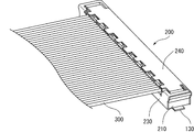
以下に本発明の実施形態を図面に基づいて説明する。図1は本発明の一実施形態を示す多極コネクタの斜視図、図2は同コネクタにおけるレセプタクルの斜視図、図3は同レセプタクルの縦断側面図、図4は同レセプタクルをプラグを組み合わせた状態の縦断側面図である。 Embodiments of the present invention will be described below with reference to the drawings. 1 is a perspective view of a multipolar connector showing an embodiment of the present invention, FIG. 2 is a perspective view of a receptacle in the connector, FIG. 3 is a longitudinal side view of the receptacle, and FIG. 4 is a state in which the receptacle is combined with a plug. FIG.
本実施形態に係る多極コネクタは、携帯電話やノート型パソコンにおける液晶表示装置とマザーボード上の基板との接続などに使用される基板実装型のコネクタである。このコネクタは、基板の表面に実装される横長のレセプタクル100と、これに装着される横長のコネクタプラグ200とからなる。コネクタプラグ200には、横に並ぶ複数本の同軸ケーブル300が正面側から挿入されて接続されている。
The multipolar connector according to the present embodiment is a board-mounted connector used for connection between a liquid crystal display device in a mobile phone or a notebook computer and a board on a motherboard. This connector includes a horizontally
基板の表面に実装されるレセプタクル100は、樹脂からなる横長のレセプタクルボディ110と、これに保持された多数個のレセプタクルコンタクト120と、レセプタクルボディ110内に長手方向の全長にわたって埋設された横長のアース部材130とを備えている。
The
レセプタクルボディ110は横に長い直方体であり、長手方向に所定間隔で形成された多数個のコンタクト挿入部111を有している。コンタクト挿入部111はボディ110の長手方向に直角なスリット状の凹部であり、ボディ110の両端部及び中央部を除く部分に設けられている。各挿入部111は、正面側の深い凹部112と、ボディ110の凸部115の上に形成された背面側の浅い部分113と、その更に背面側の貫通部114とからなり、正面側の凹部111は、レセプタクルコンタクト120を突出させるために正面側に開口している。
The
レセプタクルコンタクト120は、正面側のほぼ垂直な接点部121と、接点部121の背面側に連接された上に凸の蛇行湾曲部122と、これらを繋ぐ水平な接続部123と、蛇行湾曲部122の背面側に連続して設けられた基板実装部124とからなる。接点部121は、プラグ200の側の対応するコンタクトとの接触性を高めるために、正面側へ凸の「く」の字状に折れ曲がって、挿入部111の正面側へ突出している。
The
蛇行湾曲部122は、水平部122aとその両端部から下方へ延出した一対の垂直部122b,122cとからなる逆U状の角形湾曲部であり、ボディ110の凸部115に被さるようにして挿入部111に挿入されている。これにより、正面側の垂直部122bは、その下端部と接点部121の下端部を繋ぐ水平な接続部123と共に、挿入部111の深い凹部112に嵌合しており、水平部122aは凸部115の上の浅い部分113に嵌合している。また、背面側の垂直部122cは貫通部114に嵌合している。
The meandering
基板実装部124は、垂直部122cの下端部から背面側へ突出しており、更に基板との接続のためにボディ110から背面側へ突出している。基板実装部124の下面はボディ110の下面と同レベルである。
The
横長のアース部材130は、銅板などの板状導電性材料からなり、ボディ110内にインサート成形により長手方向に貫通して埋設されており、その両端部は基板実装部131,131として、ボディ110の両端側に突出している。アース部材130の両端部を除く埋設部分は、ボディ110の凸部115を貫通する位置に配置されており、より詳しくは、凸部115に被さる蛇行湾曲部122の水平部122a及び垂直部122b,122cの3部分から等距離となる凸部115の中央部分に位置するように配置されている。
The horizontally
両端の基板実装部131,131は、基板の表面への実装のために、レセプタクルコンタクト120の基板実装部124同様に、ボディ110の底面と同一レベルに位置している。
The
コネクタプラグ200は、基板表面に実装された前記レセプタクル100に上方から被さる横長のキャップである。このコネクタプラグ200は、樹脂からなる横長のプラグボディ210と、プラグボディ210内にインサート成形により組み合わされた多数個のプラグコンタクト220と、プラグボディ210にプラグコンタクト220と共にインサート成形により組み合わされた第1シールド部材230と、プラグボディ110に嵌合により組み合わされる第2シールド部材240とを備えている。両シールド部材230,240はアルミニウム板からなる。
The
プラグボディ210は、レセプタクル100が嵌合する横長のレセプタクル嵌合部211を下面に有している。多数個のプラグコンタクト220は、レセプタクルコンタクト120に対応してボディ210の長手方向に所定間隔で配列されている。
The
各プラグコンタクト220は、レセプタクルコンタクト120の接点部121と接触するように嵌合部211の内壁面(レセプタクルボディ110の正面に対向する正面側の内壁面)に露出した垂直な第1接点部221を一端部に有している。各プラグコンタクト220の他端部は、同軸ケーブル300の芯線310との接続のために、ボディ210の背面側の上面に露出した水平な第2接点部222である。垂直な第1接点部221は、嵌合部211の天井面に露出する水平接続部223、その先端から背面側へ傾斜して延出する傾斜接続部224を介して上方の水平な第2接点部222に接続されており、傾斜接続部224はプラグボディ210中に完全に埋設されている。
Each
第1シールド部材230は、ボディ210の正面及び正面側の上面を覆う断面が逆L字状のシールドケースであり、ボディ210の正面に露出する垂直面部231と、ボディ210の正面側の上面に露出する水平面部232とから構成されている。
The
第2シールド部材240は、プラグボディ210の背面及びプラグボディ210の上面全体を覆う断面が逆L字状のシールドカバーであり、プラグボディ210の背面に当接する垂直面部241と、垂直面部241の上端部から正面側へ水平に延出した水平面部242とから構成されている。水平面部242は、プラグボディ210の上面との間に、同軸ケーブル300が挿入されるケーブル収容部243を形成する。
The
同軸ケーブル300は、その被覆カバー330を除去して接地線320を露出させた状態でケーブル収容部243に挿入される。挿入部の先端部分では、芯線310が露出している。そして、挿入部の露出した接地線320を一括半田部400により第1シールド部材230の水平面部232及び第2シールド部材240の水平面部242に一括して半田付けすることによりグランドバーを形成している。先端部分の露出した芯線310は、対応するプラグコンタクト220の第2接点部222に半田付けにより接合されている。
The
次に、本実施形態に係る多極コネクタの使用方法及び機能について説明する。 Next, the usage method and function of the multipolar connector according to the present embodiment will be described.
レセプタクル100を基板の表面に実装する。具体的には、多数個のレセプタクルコンタクト120の各基板実装部124を基板表面の対応するパターンに半田付けにより接合する。これと共に、レセプタクルボディ110を長手方向に貫通するアース部材130の両端の実装端子部131,131を基板表面のグランドパターンに半田付けにより接合する。レセプタクルコンタクト120の各基板実装部124以外に、アース部材130の両実装端子部131,131を基板表面に接合するので、優れた接合強度が確保される。しかも、両実装端子部131,131はアース部材130の一部であり、一部品であるので、部品点数の増加が回避される。
The
また、そのアース部材130はレセプタクルボディ110にインサート成形されているので、レセプタクル10の組立工程で実装端子部131,131をレセプタクルボディ110に取り付ける必要がない。レセプタクル100の組立工程で取り付けを行うのはレセプタクルコンタクト120のみである。これにより、1工程でレセプタクル100の組立を終えることができ、2工程で問題になる工程間の移動による時間的ロスや部品変形が防止される。
Further, since the
機器組立では、基板の表面に実装されたレセプタクル100に、同軸ケーブル300が接続されたコネクタプラグ200が装着される。具体的には、コネクタプラグ200のボディ下面に形成されたレセプタクル嵌合部211にレセプタクル100が嵌合するように、レセプタクル100にコネクタプラグ200を被せる。
In the device assembly, the
レセプタクル100にコネクタプラグ200が装着されると、レセプタクル100における多数個のレセプタクルコンタクト120の各接点部121が、コネクタプラグ200において対応するプラグコンタクト220の第1接点部221に圧接する。このとき、レセプタクルコンタクト120では、接点部121と共に、弾性変形部である上に凸状の蛇行湾曲部122が弾性変形する。これらによる反発力により、確実な電気的接触が得られる。
When the
そして、この電気的接触により、同軸ケーブル300の芯線310が、プラグコンタクト220及びレセプタクルコンタクト120を介して基板上の対応するパターンと電気的に接続される。また、並列する複数本の同軸ケーブル300の各接地線320は、一括半田部400を介して、プラグ200を覆う第1シールド部材230(シールドケース)及び第2シールド部材240(シールドカバー)と電気的に接続される。
By this electrical contact, the
ここで、レセプタクルボディ110に組み込まれた多数個のレセプタクルコンタクト120に注目するならば、ボディ110をアース部材130が長手方向、すなわちレセプタクルコンタクト120の配列方向に貫通している。このため、全てのレセプタクルコンタクト120はグランドに対して位置関係が同じになり、コンタクト配列方向におけるインピーダンス特性の整合が図られる。
Here, if attention is paid to a large number of
しかも、このアース部材130は、各レセプタクルコンタクト120の蛇行湾曲部122が被さるボディ100の凸部115の中央部を貫通しており、より詳しくは、上に凸の角形状の蛇行湾曲部122を構成する水平部122a及び垂直部122b,122cの3部分から等距離となる部分に配置されている。上に凸の角形状の蛇行湾曲部122は、レセプタクルコンタクト120の弾性接触のために重要な部分であるが、必然的にこの部分でコンタクト120が下の基板から離れる。
Moreover, the
レセプタクルコンタクト120は、高速デジタル信号の伝送では、プラグコンタクト220と共に信号伝送線路を構成する。すなわち、これらは単なる接続線ではなく、信号伝送線路となるのである。このため、レセプタクルコンタクト120の各部もグランドからの位置関係が一定になることが望まれるが、蛇行湾曲部122の部分では、レセプタクルコンタクト120が下の基板から離れるために、グランドとの位置関係が部分的に崩れる原因になる。しかるに、前記アース部材130は、蛇行湾曲部122を構成する水平部122a及び垂直部122b,122cの3部分から等距離となる部分に配置されているため、大きく変形する蛇行湾曲部122の部分でも、グランドとの位置関係が一定に保たれる。その結果、多数個のレセプタクルコンタクト120は、それらの配列方向だけでなく、配列方向に直角な方向でもインピーダンス特性の整合が図られることになる。より具体的には、各レセプタクルコンタクト120での蛇行湾曲部122に起因する、コンタクト配列方向に直角な方向でのインピーダンス特性の不整合が解消される。
The
これに加え、本実施形態に係る多極コネクタでは、レセプタクルコンタクト120の正面側の接点部121と蛇行湾曲部122とを繋ぐ水平な接続部123からその下の平行な基板までの距離も、蛇行湾曲部122からアース部材130までの距離にほぼ等しくされている。また、接点部121が弾性接触するプラグコンタクト220の垂直な第1接点部221から、その正面側に平行に配置された第1シールド部材230の垂直面部231までの距離も、蛇行湾曲部122からアース部材130までの距離にほぼ等しくされている。
In addition to this, in the multipolar connector according to the present embodiment, the distance from the horizontal connecting
すなわち、個々のレセプタクルコンタクト120は、蛇行湾曲部122の部分だけでなく、基板と接合される基板実装部124を除く全ての部分で、グランドとの位置関係が一定に保たれ、インピーダンス特性の整合が図られているのである。したがって、レセプタクルコンタクト120での伝送特性が優れる。
That is, the
また、プラグ200の側のコンタクト220に注目するならば、前述したとおり、第1接点部221から、その正面側に平行に配置された第1シールド部材230の垂直面部231までの距離が、蛇行湾曲部122からアース部材130までの距離にほぼ等しくされている。更に、同軸ケーブル300の芯線310と接続される水平な第2接点部222についても、その上に平行に配置された第2シールド部材240の水平面部242までの距離が、蛇行湾曲部122からアース部材130までの距離にほぼ等しくされている。その上、第1接点部221と第2接点部222を繋ぐ水平接続部223についても、その上に平行に配置された第1シールド部材230の水平面部232までの距離が、蛇行湾曲部122からアース部材130までの距離にほぼ等しくされている。
Further, if attention is paid to the
すなわち、個々のプラグコンタクト220は、傾斜接続部224を除く全ての部分で、シールド部材(グランド)との位置関係が一定に保たれ、インピーダンス特性の整合が図られているのである。したがって、レセプタクルコンタクト120だけでなく、プラグコンタクト220での伝送特性も優れる。なお、第1シールド部材230及び第2シールド部材240は、レセプタクル100へのプラグ200の装着に伴い、レセプタクル100の側のアース部材130を介して接地される。
That is, the
上記実施形態では、レセプタクルコンタクト120は全て同じ方向を向いた1列配置であるが、接点部121が向き合う2列配置等でもよく、レセプタクルコンタクト120及びプラグコンタクト220の配列形態や各形状については上記実施形態に限定するものではない。
In the above-described embodiment, the
100 レセプタクル
110 レセプタクルボディ
120 レセプタクルコンタクト
121 接点部
122 蛇行湾曲部
123 接続部
124 基板実装部
130 アース部材
131 基板実装部
200 コネクタプラグ
210 プラグボディ
220 プラグコンタクト
221 第1接点部
222 第2接点部
223 水平部
224 傾斜部
230 第1シールド部材
240 第2シールド部材
300 同軸ケーブル
DESCRIPTION OF
Claims (10)
A portable wireless terminal or a small electronic device using the multipolar connector according to claim 1.
Priority Applications (7)
| Application Number | Priority Date | Filing Date | Title |
|---|---|---|---|
| JP2006014349A JP4722712B2 (en) | 2006-01-23 | 2006-01-23 | Portable radio terminal or small electronic device using multipolar connector and multipolar connector |
| TW095143408A TW200803065A (en) | 2006-01-23 | 2006-11-23 | Multi-pole connector, and portable wireless terminal or compact electronic device using the multi-pole connector |
| CN2006101699377A CN101009415B (en) | 2006-01-23 | 2006-12-25 | Multi-pole connector, and portable wireless terminal or compact electronic device using the multi-pole connector |
| KR1020070003100A KR100904604B1 (en) | 2006-01-23 | 2007-01-11 | Multi-pole connector, and portable wireless terminal or compact electronic device using the multi-pole connector |
| DE602007013125T DE602007013125D1 (en) | 2006-01-23 | 2007-01-19 | Multi-pin connector and the multipolar connector using portable wireless terminal or small electronic device |
| EP07250211A EP1811607B1 (en) | 2006-01-23 | 2007-01-19 | Multipolar connector, and portable radio terminal or small-sized electronic device using multipolar connector |
| US11/655,909 US7789678B2 (en) | 2006-01-23 | 2007-01-22 | Multipolar connector and portable radio terminal or small-sized electronic device using multipolar connector |
Applications Claiming Priority (1)
| Application Number | Priority Date | Filing Date | Title |
|---|---|---|---|
| JP2006014349A JP4722712B2 (en) | 2006-01-23 | 2006-01-23 | Portable radio terminal or small electronic device using multipolar connector and multipolar connector |
Publications (2)
| Publication Number | Publication Date |
|---|---|
| JP2007200575A true JP2007200575A (en) | 2007-08-09 |
| JP4722712B2 JP4722712B2 (en) | 2011-07-13 |
Family
ID=37882403
Family Applications (1)
| Application Number | Title | Priority Date | Filing Date |
|---|---|---|---|
| JP2006014349A Expired - Fee Related JP4722712B2 (en) | 2006-01-23 | 2006-01-23 | Portable radio terminal or small electronic device using multipolar connector and multipolar connector |
Country Status (7)
| Country | Link |
|---|---|
| US (1) | US7789678B2 (en) |
| EP (1) | EP1811607B1 (en) |
| JP (1) | JP4722712B2 (en) |
| KR (1) | KR100904604B1 (en) |
| CN (1) | CN101009415B (en) |
| DE (1) | DE602007013125D1 (en) |
| TW (1) | TW200803065A (en) |
Families Citing this family (10)
| Publication number | Priority date | Publication date | Assignee | Title |
|---|---|---|---|---|
| DE102009019626B3 (en) * | 2009-04-30 | 2011-03-03 | Tyco Electronics Amp Gmbh | Electrical connector with impedance correcting element and method of making the same |
| TW201104979A (en) * | 2009-07-29 | 2011-02-01 | Adv Flexible Circuits Co Ltd | Circuit substrate inserting and positioning connector |
| JP2012146573A (en) * | 2011-01-13 | 2012-08-02 | Hitachi Cable Ltd | Flat cable and connection structure between flat cable and printed wiring board |
| JP2012234634A (en) * | 2011-04-28 | 2012-11-29 | Hitachi Cable Ltd | Flat cable and connection structure of flat cable and printed wiring board |
| JP5796256B2 (en) * | 2011-12-15 | 2015-10-21 | ホシデン株式会社 | Flexible flat cable |
| US9112302B2 (en) * | 2013-05-02 | 2015-08-18 | Hon Hai Precision Industry Co., Ltd. | Electrical connector and assembly thereof |
| JP6891046B2 (en) * | 2017-05-31 | 2021-06-18 | ヒロセ電機株式会社 | Electrical connector with power terminal |
| US10777924B1 (en) * | 2019-03-05 | 2020-09-15 | Dell Products L.P. | Connector receptacle |
| JP7180757B2 (en) * | 2019-03-29 | 2022-11-30 | 株式会社村田製作所 | Multi-pole connector set |
| JP7363440B2 (en) * | 2019-12-10 | 2023-10-18 | 株式会社オートネットワーク技術研究所 | connector |
Citations (5)
| Publication number | Priority date | Publication date | Assignee | Title |
|---|---|---|---|---|
| JPH08321358A (en) * | 1995-05-25 | 1996-12-03 | Kel Corp | Connector with gland plate |
| JPH11354232A (en) * | 1998-06-10 | 1999-12-24 | Alps Electric Co Ltd | Connector for ic card connector device |
| US6190206B1 (en) * | 2000-03-29 | 2001-02-20 | Tai-Her Yang | Conductor coupling incorporating a convexo-concave coupling labyrinth separator |
| JP2003217711A (en) * | 2002-01-28 | 2003-07-31 | Matsushita Electric Works Ltd | Connector |
| JP2005019009A (en) * | 2003-06-23 | 2005-01-20 | Matsushita Electric Ind Co Ltd | Surface-mounted electronic component and electronic circuit device using the same |
Family Cites Families (12)
| Publication number | Priority date | Publication date | Assignee | Title |
|---|---|---|---|---|
| US4687267A (en) * | 1986-06-27 | 1987-08-18 | Amp Incorporated | Circuit board edge connector |
| FR2704696B1 (en) * | 1993-04-27 | 1996-05-31 | Rudolf Gorlich | Plug connector for printed circuit boards. |
| JP3617220B2 (en) * | 1996-11-26 | 2005-02-02 | 松下電工株式会社 | connector |
| US5915976A (en) * | 1997-02-06 | 1999-06-29 | Hon Hai Precision Ind. Co., Ltd. | High speed connector |
| JP3277154B2 (en) * | 1998-05-06 | 2002-04-22 | ケル株式会社 | connector |
| JP4324822B2 (en) | 1999-05-21 | 2009-09-02 | 株式会社アイペックス | Cable connector |
| US6702590B2 (en) | 2001-06-13 | 2004-03-09 | Molex Incorporated | High-speed mezzanine connector with conductive housing |
| SG98466A1 (en) * | 2001-12-28 | 2003-09-19 | Fci Asia Technology Pte Ltd | An electrical connector |
| EP1523788B1 (en) | 2002-07-23 | 2011-03-02 | Panasonic Electric Works Co., Ltd. | Low-profile connector |
| KR100511180B1 (en) * | 2003-02-19 | 2005-08-30 | 재영솔루텍 주식회사 | Production method of electric-connector |
| JP2005071669A (en) | 2003-08-20 | 2005-03-17 | Matsushita Electric Works Ltd | Connector for cable connection |
| JP2005116447A (en) * | 2003-10-10 | 2005-04-28 | Sony Corp | Connector and electronic apparatus |
-
2006
- 2006-01-23 JP JP2006014349A patent/JP4722712B2/en not_active Expired - Fee Related
- 2006-11-23 TW TW095143408A patent/TW200803065A/en not_active IP Right Cessation
- 2006-12-25 CN CN2006101699377A patent/CN101009415B/en not_active Expired - Fee Related
-
2007
- 2007-01-11 KR KR1020070003100A patent/KR100904604B1/en not_active IP Right Cessation
- 2007-01-19 DE DE602007013125T patent/DE602007013125D1/en active Active
- 2007-01-19 EP EP07250211A patent/EP1811607B1/en not_active Expired - Fee Related
- 2007-01-22 US US11/655,909 patent/US7789678B2/en not_active Expired - Fee Related
Patent Citations (5)
| Publication number | Priority date | Publication date | Assignee | Title |
|---|---|---|---|---|
| JPH08321358A (en) * | 1995-05-25 | 1996-12-03 | Kel Corp | Connector with gland plate |
| JPH11354232A (en) * | 1998-06-10 | 1999-12-24 | Alps Electric Co Ltd | Connector for ic card connector device |
| US6190206B1 (en) * | 2000-03-29 | 2001-02-20 | Tai-Her Yang | Conductor coupling incorporating a convexo-concave coupling labyrinth separator |
| JP2003217711A (en) * | 2002-01-28 | 2003-07-31 | Matsushita Electric Works Ltd | Connector |
| JP2005019009A (en) * | 2003-06-23 | 2005-01-20 | Matsushita Electric Ind Co Ltd | Surface-mounted electronic component and electronic circuit device using the same |
Also Published As
| Publication number | Publication date |
|---|---|
| TWI318813B (en) | 2009-12-21 |
| US7789678B2 (en) | 2010-09-07 |
| KR100904604B1 (en) | 2009-06-25 |
| KR20070077440A (en) | 2007-07-26 |
| US20070173116A1 (en) | 2007-07-26 |
| EP1811607A1 (en) | 2007-07-25 |
| CN101009415A (en) | 2007-08-01 |
| CN101009415B (en) | 2011-04-06 |
| EP1811607B1 (en) | 2011-03-16 |
| DE602007013125D1 (en) | 2011-04-28 |
| TW200803065A (en) | 2008-01-01 |
| JP4722712B2 (en) | 2011-07-13 |
Similar Documents
| Publication | Publication Date | Title |
|---|---|---|
| JP4722712B2 (en) | Portable radio terminal or small electronic device using multipolar connector and multipolar connector | |
| US9948041B2 (en) | Electrical receptacle connector for providing grounding and reducing electromagnetic interference | |
| US9935401B2 (en) | Electrical receptacle connector | |
| US9525244B1 (en) | Electrical connector with and inner grounding unit and an outer grounding unit | |
| US9660399B2 (en) | Electrical connector with two insertion orientations | |
| US9742095B2 (en) | Electrical receptacle connector | |
| US9455530B2 (en) | Electrical connector with ground bus | |
| CN106921060B (en) | Rigid-flexible circuit connector | |
| TWI558006B (en) | First and second connectors mating with each other | |
| TW202029595A (en) | Connector and connector assembly | |
| US9190752B1 (en) | Board to board connector assembly having improved terminal arrangement | |
| US9812826B2 (en) | Electrical connector with grounding contact | |
| US9640925B2 (en) | Stacked right angle connectors | |
| JP6703900B2 (en) | Connectors and connector systems | |
| US8353728B2 (en) | Receptacle connector having contact modules and plug connector having a paddle board | |
| JP4843263B2 (en) | Connector for flexible printed cable | |
| US8506333B2 (en) | Connector assembly having front and rear rows of terminals with differently leveled contacting portions | |
| US7686618B2 (en) | Connector and connector device | |
| US20170294726A1 (en) | Electrical receptacle connector | |
| US10651612B2 (en) | Electrical connector with lower profile | |
| US9711912B2 (en) | Cable connector assembly with improved insulative member | |
| US9124036B2 (en) | Electrical connector with improved grounding member for cross-talk prevention | |
| JP2006331711A (en) | Connector | |
| JP2006331898A (en) | Transmission cable and connector for transmission cable | |
| JP4563250B2 (en) | Connector, receptacle connector, and portable wireless terminal or small electronic device |
Legal Events
| Date | Code | Title | Description |
|---|---|---|---|
| A621 | Written request for application examination |
Free format text: JAPANESE INTERMEDIATE CODE: A621 Effective date: 20080929 |
|
| A977 | Report on retrieval |
Free format text: JAPANESE INTERMEDIATE CODE: A971007 Effective date: 20101129 |
|
| A131 | Notification of reasons for refusal |
Free format text: JAPANESE INTERMEDIATE CODE: A131 Effective date: 20101207 |
|
| A521 | Request for written amendment filed |
Free format text: JAPANESE INTERMEDIATE CODE: A523 Effective date: 20110121 |
|
| TRDD | Decision of grant or rejection written | ||
| A01 | Written decision to grant a patent or to grant a registration (utility model) |
Free format text: JAPANESE INTERMEDIATE CODE: A01 Effective date: 20110405 |
|
| A01 | Written decision to grant a patent or to grant a registration (utility model) |
Free format text: JAPANESE INTERMEDIATE CODE: A01 |
|
| A61 | First payment of annual fees (during grant procedure) |
Free format text: JAPANESE INTERMEDIATE CODE: A61 Effective date: 20110406 |
|
| FPAY | Renewal fee payment (event date is renewal date of database) |
Free format text: PAYMENT UNTIL: 20140415 Year of fee payment: 3 |
|
| R150 | Certificate of patent or registration of utility model |
Ref document number: 4722712 Country of ref document: JP Free format text: JAPANESE INTERMEDIATE CODE: R150 Free format text: JAPANESE INTERMEDIATE CODE: R150 |
|
| LAPS | Cancellation because of no payment of annual fees |