JP2007200418A - Objective lens actuator and optical pickup device provided with the same - Google Patents
Objective lens actuator and optical pickup device provided with the same Download PDFInfo
- Publication number
- JP2007200418A JP2007200418A JP2006015975A JP2006015975A JP2007200418A JP 2007200418 A JP2007200418 A JP 2007200418A JP 2006015975 A JP2006015975 A JP 2006015975A JP 2006015975 A JP2006015975 A JP 2006015975A JP 2007200418 A JP2007200418 A JP 2007200418A
- Authority
- JP
- Japan
- Prior art keywords
- objective lens
- recording medium
- optical recording
- collision
- contact
- Prior art date
- Legal status (The legal status is an assumption and is not a legal conclusion. Google has not performed a legal analysis and makes no representation as to the accuracy of the status listed.)
- Pending
Links
Images


Classifications
-
- G—PHYSICS
- G11—INFORMATION STORAGE
- G11B—INFORMATION STORAGE BASED ON RELATIVE MOVEMENT BETWEEN RECORD CARRIER AND TRANSDUCER
- G11B7/00—Recording or reproducing by optical means, e.g. recording using a thermal beam of optical radiation by modifying optical properties or the physical structure, reproducing using an optical beam at lower power by sensing optical properties; Record carriers therefor
- G11B7/08—Disposition or mounting of heads or light sources relatively to record carriers
- G11B7/09—Disposition or mounting of heads or light sources relatively to record carriers with provision for moving the light beam or focus plane for the purpose of maintaining alignment of the light beam relative to the record carrier during transducing operation, e.g. to compensate for surface irregularities of the latter or for track following
- G11B7/0925—Electromechanical actuators for lens positioning
- G11B7/0935—Details of the moving parts
Abstract
Description
本発明は、光記録媒体に光ビームを照射して情報の記録や情報の読み取りを可能とする光ピックアップ装置に搭載される対物レンズアクチュエータに関し、特に対物レンズと光記録媒体との衝突を防止できる対物レンズアクチュエータの構造に関する。また、本発明は、そのような対物レンズアクチュエータを備える光ピックアップ装置に関する。 The present invention relates to an objective lens actuator that is mounted on an optical pickup device capable of recording information and reading information by irradiating an optical recording medium with a light beam, and in particular, can prevent collision between the objective lens and the optical recording medium. The present invention relates to the structure of an objective lens actuator. The present invention also relates to an optical pickup device including such an objective lens actuator.
コンパクトディスク(以下、CDという。)やデジタル多用途ディスク(以下、DVDという。)といった光記録媒体が普及している。更に、近年、光記録媒体の情報量を増やすために、光記録媒体の高密度化に関する研究が進められ、例えば、高品位のDVDであるHD−DVDやブルーレイディスク(以下、BDという。)といった高密度化された光記録媒体も実用化されつつある。 Optical recording media such as compact discs (hereinafter referred to as CDs) and digital versatile discs (hereinafter referred to as DVDs) are widely used. Further, in recent years, in order to increase the amount of information in an optical recording medium, research on increasing the density of the optical recording medium has been promoted. High-density optical recording media are also being put into practical use.
このような光記録媒体の記録再生を行うにあたっては、光記録媒体に光ビームを照射して情報の記録や情報の読み取りを可能とする光ピックアップ装置が用いられるが、BDのような高密度化された光記録媒体について、光ピックアップ装置を用いて情報の記録や情報の読み取りを行う場合、光ピックアップ装置に備えられる光源の波長を短くし(BDでは、例えば405nm)、更に対物レンズの開口数(NA)を大きくして(BDでは、例えばNA=0.85)、光源から出射される光ビームが光記録媒体上に形成する光ビームのスポットサイズを小さくする必要がある。そして、このように対物レンズの開口数を大きくした場合、光ピックアップ装置により光記録媒体の情報の記録再生を行う際の対物レンズ先端と光記録媒体との間隔(ワーキングディスタンス;WD)が非常に狭くなる。 When performing recording / reproduction of such an optical recording medium, an optical pickup device capable of recording information or reading information by irradiating the optical recording medium with a light beam is used. When recording information or reading information using the optical pickup device, the wavelength of the light source provided in the optical pickup device is shortened (for example, 405 nm for BD), and the numerical aperture of the objective lens is further reduced. It is necessary to increase (NA) (in the BD, for example, NA = 0.85) to reduce the spot size of the light beam formed on the optical recording medium by the light beam emitted from the light source. When the numerical aperture of the objective lens is increased in this way, the distance (working distance; WD) between the tip of the objective lens and the optical recording medium when recording / reproducing information on the optical recording medium by the optical pickup device is very high. Narrow.
ところで、光ピックアップ装置においては、光記録媒体の面振れ等によらず、光源から出射される光ビームの焦点が常に光記録媒体の記録面に合うように、対物レンズアクチュエータにより、対物レンズを駆動することによって、対物レンズと光記録媒体との位置関係を一定に制御する。以下、このような制御をフォーカスサーボと表現することがある。 By the way, in the optical pickup device, the objective lens is driven by the objective lens actuator so that the focal point of the light beam emitted from the light source always matches the recording surface of the optical recording medium regardless of the surface shake of the optical recording medium. By doing so, the positional relationship between the objective lens and the optical recording medium is controlled to be constant. Hereinafter, such control may be expressed as focus servo.
しかし、上述のように、近年の光ピックアップ装置においては、WDが非常に狭くなる傾向に有り、例えば、光記録媒体上の傷や外部からの振動によりフォーカスサーボが外れた場合に、対物レンズと光記録媒体とが衝突する可能性が非常に高くなっている。このようなことから、従来、対物レンズと光記録媒体の衝突によって、光記録媒体に記録される情報が使えなくなったり、対物レンズが損傷して光ピックアップ装置が使用できなくなったりするのを防止するために、様々な技術が提案されている。 However, as described above, in recent optical pickup devices, the WD tends to be very narrow. For example, when the focus servo is removed due to scratches on the optical recording medium or external vibrations, The possibility of collision with the optical recording medium is very high. For this reason, conventionally, it is possible to prevent the information recorded on the optical recording medium from being used due to the collision between the objective lens and the optical recording medium, or the objective lens from being damaged and the optical pickup device from being used. Various techniques have been proposed for this purpose.
例えば、特許文献1においては、対物レンズのフランジに突起状の緩衝部を設け、これにより対物レンズと光記録媒体とが直接接触するのを防止する技術を提案している。また、特許文献2においては、対物レンズを移動可能とする対物レンズ駆動装置(対物レンズアクチュエータ)が備える対物レンズホルダの上面に、弾性接着剤で形成した突起状のレンズ衝突防止部材を配置し、これにより対物レンズと光記録媒体とが衝突するのを防止する技術が提案されている。
For example,
また、特許文献3においては、基部に固着される弾性部材により支持され、光記録媒体の回転により光記録媒体に対して浮上する浮上型スライダーを光記録媒体と対物レンズホルダとの間に配置し、対物レンズと光記録媒体との衝突を防止する技術を提案している。更に、特許文献4においては、光記録媒体に配設した磁性層の磁界、もしくは光記録媒体を挟んで対物レンズと反対側に配設した磁性体又は磁界発生手段の磁界と、フォーカス用のアクチュエータコイルによる磁界、もしくは対物レンズ保持部に配置された磁性体又は磁界発生手段と、の斥力により、対物レンズと光記録媒体との衝突を防止する技術について提案されている。
In
しかしながら、特許文献1や2に提案される構成の場合、突起状に設けられる緩衝部又はレンズ衝突防止部材が光記録媒体に接触した際に、接触時の衝撃や回転している光記録媒体との摩擦力のために、光記録媒体の表面に傷が生じるという問題があった。この点、特許文献3や特許文献4の構成の場合には、基本的には光記録媒体が対物レンズやレンズ衝突防止部材等と接触することがないため、特許文献1や2の場合と比べて光記録媒体の表面に傷が発生し難い。
However, in the case of the configuration proposed in
しかし、特許文献3の構成のように基部に機械的ストッパーを設ける構成の場合には、特許文献1や2の場合に比べて衝突防止用に設ける部材の構成が大きくなるために、光ピックアップ装置を組み立てる際に、ストッパーの位置の調整が難しくなるといった欠点がある。また、弾性部材に支持された浮上型スライダーは、揺動し易く動作が安定し難いために、光記録媒体と衝突する可能性が高いという欠点もある。
However, in the configuration in which the mechanical stopper is provided at the base as in the configuration of
また、特許文献4の構成の場合、光記録媒体の構成が複雑となるか、又は光記録媒体を挟んで対物レンズと反対側に磁性体等を配設する構成であるために、装置の大型化に繋がるといった問題等がある。
以上の点を鑑みて、本発明の目的は、対物レンズと光記録媒体との衝突を防止できる機能を有し、更に光記録媒体を損傷することがない簡易な構成の対物レンズアクチュエータを提供することである。また、本発明の他の目的は、対物レンズ及び光記録媒体への損傷が発生しにくい対物レンズアクチュエータを備えることにより、情報の記録再生を安定して行える光ピックアップ装置を提供することである。 In view of the above points, an object of the present invention is to provide an objective lens actuator having a function of preventing collision between an objective lens and an optical recording medium and having a simple configuration that does not damage the optical recording medium. That is. Another object of the present invention is to provide an optical pickup device that can stably record and reproduce information by providing an objective lens actuator that is less likely to damage the objective lens and the optical recording medium.
上記目的を達成するために本発明は、光源と、該光源から出射された光束を光記録媒体の記録面に集束する対物レンズと、該対物レンズの光軸方向に延びる空洞部を有し、前記対物レンズを前記空洞部の前記光記録媒体側で保持する対物レンズホルダと、該対物レンズホルダを磁力によって駆動するための磁気回路と、を有し、前記対物レンズホルダの前記対物レンズが保持される側には、前記対物レンズホルダから突出して前記対物レンズと前記光記録媒体との衝突を防止する衝突防止部材が設けられる対物レンズアクチュエータと、を備える光ピックアップ装置において、前記衝突防止部材は、少なくとも2つ設けられて前記対物レンズを挟んで略対称な位置に配置され、また、前記対物レンズホルダと固着する固着部と、該固着部から前記光記録媒体に対して所定量傾いて前記光記録媒体の回転方向と同方向に延びる傾斜部と、該傾斜部から延び、前記記録面と略平行となる面を有して前記光記録媒体と接触することがある接触部と、から成って、前記光記録媒体と接触した際に、前記対物レンズホルダ側に撓むように形成されることを特徴としている。 In order to achieve the above object, the present invention has a light source, an objective lens that focuses a light beam emitted from the light source on a recording surface of an optical recording medium, and a cavity that extends in the optical axis direction of the objective lens, An objective lens holder that holds the objective lens on the optical recording medium side of the cavity, and a magnetic circuit for driving the objective lens holder by a magnetic force, and the objective lens of the objective lens holder holds the objective lens holder And an objective lens actuator provided with a collision prevention member that protrudes from the objective lens holder and prevents a collision between the objective lens and the optical recording medium. , At least two, disposed at substantially symmetrical positions across the objective lens, and a fixing portion that is fixed to the objective lens holder; and The optical recording medium having an inclined portion inclined by a predetermined amount with respect to the optical recording medium and extending in the same direction as the rotation direction of the optical recording medium, and a surface extending from the inclined portion and substantially parallel to the recording surface And a contact portion that may come into contact with the optical recording medium, and is formed so as to bend toward the objective lens holder when it comes into contact with the optical recording medium.
また、上記目的を達成するために本発明は、対物レンズと、該対物レンズの光軸方向に延びる空洞部を有し、前記対物レンズを前記空洞部の光記録媒体側で保持する対物レンズホルダと、該対物レンズホルダを磁力によって駆動するための磁気回路と、を備え、前記対物レンズホルダの前記対物レンズが保持される側には、前記対物レンズホルダから突出して前記対物レンズと前記光記録媒体との衝突を防止する衝突防止部材が設けられる対物レンズアクチュエータにおいて、前記衝突防止部材に、前記衝突防止部材と前記光記録媒体との接触による前記光記録媒体の損傷を防止する光記録媒体損傷防止機構を設けたことを特徴としている。 In order to achieve the above object, the present invention provides an objective lens holder having an objective lens and a cavity extending in the optical axis direction of the objective lens, and holding the objective lens on the optical recording medium side of the cavity. And a magnetic circuit for driving the objective lens holder by magnetic force, and the objective lens and the optical recording are projected from the objective lens holder on the side of the objective lens holder where the objective lens is held. In an objective lens actuator provided with a collision preventing member for preventing a collision with a medium, the optical recording medium damage for preventing the optical recording medium from being damaged due to contact between the collision preventing member and the optical recording medium. A prevention mechanism is provided.
また、本発明は、上記構成の対物レンズアクチュエータにおいて、前記光記録媒体損傷防止機構は、前記衝突防止部材と前記光記録媒体とが接触した時に、前記衝突防止部材が前記対物レンズホルダ側に撓む機構であることを特徴としている。 In the objective lens actuator configured as described above, the optical recording medium damage prevention mechanism may be configured such that when the collision prevention member and the optical recording medium come into contact with each other, the collision prevention member bends toward the objective lens holder. It is characterized by a mechanism.
また、本発明は、上記構成の対物レンズアクチュエータにおいて、前記衝突防止部材の前記光記録媒体との接触時に前記対物レンズホルダ側に撓む部分は、前記光記録媒体の回転に伴う前記光記録媒体と前記衝突防止部材との接触圧の上昇を抑制する向きに配置されることを特徴としている。 Further, according to the present invention, in the objective lens actuator configured as described above, the portion of the collision prevention member that is bent toward the objective lens holder when contacting the optical recording medium is the optical recording medium that accompanies the rotation of the optical recording medium. And the anti-collision member are arranged in a direction to suppress an increase in contact pressure.
また、本発明は、上記構成の対物レンズアクチュエータにおいて、前記衝突防止部材は、前記対物レンズホルダと固着する固着部と、該固着部から前記光記録媒体に対し所定量傾いて前記光記録媒体の回転方向と同方向に延びる傾斜部と、該傾斜部から延び、前記光記録媒体の記録面と略平行となる面を有して前記光記録媒体と接触することがある接触部と、から成ることを特徴としている。 According to the present invention, in the objective lens actuator having the above-described configuration, the collision prevention member includes a fixing portion fixed to the objective lens holder, and a predetermined amount of inclination from the fixing portion with respect to the optical recording medium. An inclined portion extending in the same direction as the rotation direction, and a contact portion extending from the inclined portion and having a surface substantially parallel to the recording surface of the optical recording medium and may contact the optical recording medium. It is characterized by that.
また、本発明は、上記構成の対物レンズアクチュエータにおいて、前記衝突防止部材の先端部にローラが設けられ、前記ローラは、前記衝突防止部材が前記光記録媒体と接触した時に、前記光記録媒体の回転に伴って回転するように形成されることを特徴としている。 According to the present invention, in the objective lens actuator configured as described above, a roller is provided at a tip portion of the collision preventing member, and the roller of the optical recording medium is in contact with the optical recording medium when the collision preventing member is in contact with the optical recording medium. It is characterized by being formed so as to rotate with rotation.
また、本発明は、上記構成の対物レンズアクチュエータにおいて、前記衝突防止部材の先端部は翼状に形成され、
前記翼状に形成される先端部は、前記光記録媒体の回転に伴う空気の流れによって前記対物レンズホルダ方向に力を受けるように配置されることを特徴としている。
Further, in the objective lens actuator having the above-described configuration, the tip of the collision preventing member is formed in a wing shape.
The tip formed in the wing shape is arranged so as to receive a force in the direction of the objective lens holder by the air flow accompanying the rotation of the optical recording medium.
また、本発明は、上記構成の対物レンズアクチュエータにおいて、前記衝突防止部材は少なくとも2つ設けられ、前記対物レンズを挟んで略対称な位置に配置されることを特徴としている。 According to the present invention, in the objective lens actuator having the above-described configuration, at least two collision preventing members are provided, and are arranged at substantially symmetrical positions with the objective lens interposed therebetween.
また、本発明は、上記構成の対物レンズアクチュエータを備える光ピックアップ装置であることを特徴としている。 Further, the present invention is an optical pickup device including the objective lens actuator configured as described above.
本発明の第1の構成によれば、衝突防止部材は、対物レンズと光記録媒体の衝突を防止するばかりではなく、衝突防止部材と光記録媒体とが接触した時に、衝突防止部材が撓むように構成されているために、衝突防止部材と光記録媒体との間の接触時の衝撃を緩和し、衝突防止部材と光記録媒体との接触圧を低減することができる。そして、撓む部分が光記録媒体の回転に伴う光記録媒体と衝突防止部材との接触圧の上昇を抑制する向きに配置されているために、光記録媒体に過大な負荷がかかり難い。このため、光ピックアップ装置が備える対物レンズと光記録媒体とのいずれもについて損傷する可能性が低減され、情報の記録再生を安定して行える光ピックアップ装置を提供することが可能となる。 According to the first configuration of the present invention, the collision prevention member not only prevents the collision between the objective lens and the optical recording medium, but also causes the collision prevention member to bend when the collision prevention member and the optical recording medium come into contact with each other. Since it is configured, the impact at the time of contact between the collision prevention member and the optical recording medium can be reduced, and the contact pressure between the collision prevention member and the optical recording medium can be reduced. Since the bent portion is arranged in such a direction as to suppress an increase in contact pressure between the optical recording medium and the collision preventing member accompanying the rotation of the optical recording medium, it is difficult to apply an excessive load to the optical recording medium. Therefore, the possibility of damaging both the objective lens and the optical recording medium included in the optical pickup device is reduced, and it becomes possible to provide an optical pickup device that can stably record and reproduce information.
また、本発明の第2の構成によれば、衝突防止部材は、対物レンズと光記録媒体の衝突を防止するばかりではなく、衝突防止部材と光記録媒体との接触による光記録媒体の損傷を防止する機構をも有しているために、対物レンズの損傷を防止できるばかりでなく、光記録媒体の損傷も防止することが可能となる。 According to the second configuration of the present invention, the collision preventing member not only prevents the collision between the objective lens and the optical recording medium but also damages the optical recording medium due to the contact between the collision preventing member and the optical recording medium. Since it also has a mechanism for preventing the damage, it is possible not only to prevent the objective lens from being damaged, but also to prevent the optical recording medium from being damaged.
また、本発明の第3の構成によれば、上記第2の構成の対物レンズアクチュエータにおいて、衝突防止部材が光記録媒体に接触した時に、対物レンズホルダ側に撓むために、衝突防止部材と対物レンズホルダとが接触した時の衝撃が緩和され、また、衝突防止部材と光記録媒体との接触圧を低減することが可能となる。このため、両者の接触が発生しても光記録媒体の損傷が発生し難くなる。 According to the third configuration of the present invention, in the objective lens actuator having the second configuration, when the collision prevention member comes into contact with the optical recording medium, the collision prevention member and the objective lens are bent to be bent toward the objective lens holder. The impact when the holder comes into contact is alleviated, and the contact pressure between the collision preventing member and the optical recording medium can be reduced. For this reason, even if both contact occurs, the optical recording medium is hardly damaged.
また、本発明の第4の構成によれば、上記第3の構成の対物レンズアクチュエータにおいて、衝突防止部材と光記録媒体とが接触し、光記録媒体が回転を続けても光記録媒体へ過大な負荷がかかり難く、光記録媒体の損傷を防止しやすい。 According to the fourth configuration of the present invention, in the objective lens actuator having the third configuration, the collision preventing member and the optical recording medium are in contact with each other, and the optical recording medium is excessively large even if the optical recording medium continues to rotate. It is difficult to apply a heavy load and it is easy to prevent damage to the optical recording medium.
また、本発明の第5の構成によれば、上記第4の構成の対物レンズアクチュエータにおいて、光記録媒体の損傷が発生しにくい衝突防止部材の構成を簡易な構成で実現できる。 Further, according to the fifth configuration of the present invention, in the objective lens actuator having the fourth configuration described above, the configuration of the collision preventing member that is less likely to cause damage to the optical recording medium can be realized with a simple configuration.
また、本発明の第6の構成によれば、上記第2の構成の対物レンズアクチュエータにおいて、衝突防止部材と光記録媒体とが接触しても、光記録媒体の回転に合わせて衝突防止部材に設けられるローラが回転するために、衝突防止部材と光記録媒体との間で起こる摩擦力が低減され、両者の接触が発生しても光記録媒体の損傷は発生しにくい。 According to the sixth configuration of the present invention, in the objective lens actuator having the second configuration described above, even if the collision preventing member and the optical recording medium come into contact with each other, the collision preventing member is synchronized with the rotation of the optical recording medium. Since the roller provided rotates, the frictional force generated between the collision preventing member and the optical recording medium is reduced, and the optical recording medium is unlikely to be damaged even if contact between both occurs.
また、本発明の第7の構成によれば、上記第2の構成の対物レンズアクチュエータにおいて、光記録媒体が回転している場合には、先端部が翼状に形成される衝突防止部材は、対物レンズホルダ方向に力を受けるために、衝突防止部材と光記録媒体との接触を回避するか、又は両者が接触しても、その際の衝撃を緩和できる。このため、光記録媒体が損傷する可能性は低い。 According to the seventh configuration of the present invention, in the objective lens actuator having the second configuration, when the optical recording medium is rotated, the collision preventing member whose tip is formed in a wing shape is the objective lens actuator. Since the force is received in the direction of the lens holder, it is possible to avoid the contact between the collision preventing member and the optical recording medium, or to reduce the impact at that time even if both contact. For this reason, the possibility that the optical recording medium is damaged is low.
また、本発明の第8の構成によれば、上記第2から第7のいずれかの構成の対物レンズアクチュエータにおいて、衝突防止部材の効果を発揮しやすい配置であるため、光記録媒体を損傷する可能性を更に低減できる。 Further, according to the eighth configuration of the present invention, the objective lens actuator having any one of the second to seventh configurations is arranged to easily exert the effect of the collision preventing member, and thus damages the optical recording medium. The possibility can be further reduced.
また、本発明の第9の構成によれば、上記第2から第8のいずれかの構成の対物レンズアクチュエータを備える光ピックアップ装置において、対物レンズ及び光記録媒体の損傷が発生しにくいため情報の記録再生を安定して行うことが可能となる。 According to the ninth configuration of the present invention, in the optical pickup device including the objective lens actuator having any one of the second to eighth configurations, the objective lens and the optical recording medium are not easily damaged. Recording and reproduction can be performed stably.
以下に本発明の実施形態を、図面を参照しながら説明する。なお、ここで示す実施形態は一例であり、本発明はここに示す実施形態に限定されるものではない。 Embodiments of the present invention will be described below with reference to the drawings. In addition, embodiment shown here is an example and this invention is not limited to embodiment shown here.
図1は、本発明の対物レンズアクチュエータを備える光ピックアップ装置の光学系を示す概略図である。図1において、1は光ピックアップ装置で、例えば、CD、DVD、BD等の光記録媒体9に対して、光ビームを照射して反射光を受光することにより光記録媒体9の記録面9aに記録されている情報を読み取ったり、光記録媒体9に光ビームを照射して記録面9aに情報を書き込んだりすることを可能とする装置である。この光ピックアップ装置1の光学系は、例えば、光源2と、ビームスプリッタ3と、コリメートレンズ4と、立ち上げミラー5と、1/4波長板6と、対物レンズ7と、光検出器8と、を備えている。以下に、各光学素子の詳細を説明する。
FIG. 1 is a schematic view showing an optical system of an optical pickup device provided with the objective lens actuator of the present invention. In FIG. 1,
光源2は、半導体レーザで構成されており、光ピックアップ装置1が例えば、BD用の光ピックアップ装置である場合には、光源2は、例えば405nm帯の光ビームを出射する。また、光ピックアップ装置1がCD用又はDVD用のものであれば、例えば、光源2はそれぞれ780nm帯、650nm帯の光ビームを出射する。
The
なお、本実施形態においては、単一の波長を有する光源を1つだけ配置する構成としているが、これに限定される趣旨ではなく、例えば、単一の波長を有する光源を複数個配置する構成等としても構わない。また、光源として、例えば2波長1パッケージタイプの光源を用いる構成等としても構わない。 In the present embodiment, only one light source having a single wavelength is arranged. However, the present invention is not limited to this. For example, a plurality of light sources having a single wavelength are arranged. And so on. Further, as the light source, for example, a configuration using a light source of two wavelengths and one package type may be used.
ビームスプリッタ3は、光ビームを分離する分離素子として機能し、光源2から出射された光ビームを透過して光記録媒体側9へと導くとともに、光記録媒体9で反射された反射光を反射して光検出器8へと導く。ビームスプリッタ3を透過した光ビームは、コリメートレンズ4に送られる。
The
コリメートレンズ4は、ビームスプリッタ3を透過した光ビームを平行光に変換するレンズである。ここで、平行光とは、光源2から出射された光ビームの全ての光路が光軸とほぼ平行である光をいう。コリメートレンズ4を透過した平行光は、立ち上げミラー5に送られる。
The
立ち上げミラー5は、コリメートレンズ4を透過してきた光ビームを反射して光記録媒体9へと導く。立ち上げミラー5は、コリメートレンズ4からの光ビームの光軸に対して45°傾いた状態となっており、立ち上げミラー5で反射された光ビームの光軸は、光記録媒体9の記録面9aと略直交する。立ち上げミラー5で反射された光ビームは、1/4波長板6へと送られる。
The raising
1/4波長板6は、光源2から出射され、立ち上げミラー5で反射された直線偏光の光ビームを円偏光へと変換する。1/4波長板6を透過した光ビームは、対物レンズ7へと送られる。
The quarter-wave plate 6 converts the linearly polarized light beam emitted from the
対物レンズ7は、1/4波長板6を透過した光ビームを光記録媒体9の記録面9a上に集光させる。対物レンズ7の開口数(NA)は、光ピックアップ装置1がBD用の場合は、例えばNA=0.85とされる。また、光ピックアップ装置1が、例えば、CD用、DVD用の場合には、それぞれ、NA=0.5、NA=0.65とされる。この対物レンズ7は、後述する対物レンズアクチュエータに搭載されており、所定の方向に移動できるように構成されている。
The
光記録媒体9で反射された反射光は、対物レンズ7、1/4波長板6を透過する。1/4波長板6を透過する反射光は、直線偏光に変換されるが、この際、直線偏光の偏光角は、光源2から出射される光ビームの偏光角と90°ずれている。1/4波長板6を透過した反射光は、立ち上げミラー5で反射され、コリメートレンズ4を通過した後のビームスプリッタ3で反射されて光検出器8の受光部(図示せず)に到達する。
The reflected light reflected by the
光検出器8は、受光した光情報を電気信号に変換して、例えば、図示しないRFアンプ等に出力する。そして、この電気信号は、記録面9aに記録されているデータの再生信号として、更には、フォーカス制御やトラッキング制御を行うためのサーボ制御用の信号として用いられる。
The
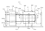
次に、光ピックアップ装置1が備える第1実施形態の対物レンズアクチュエータ11の詳細について、図2から図4を参照しながら説明する。ここで、図2は、第1実施形態の対物レンズアクチュエータ11の構成を示す概略上面図、図3は、第1実施形態の対物レンズアクチュエータ11の構成を示す概略側面図、図4は、図3のA−A断面図である。
Next, details of the
対物レンズアクチュエータ11は、大きくは、強磁性を有する金属性のベース部材12と、樹脂成型品の対物レンズホルダ13と、より構成される。ベース部材12のほぼ中央には、光源2(図1参照)からの光ビームを通過させる貫通穴(図示せず)が形成され、詳細は後述する対物レンズホルダ13が配置される。また、ベース部材12上には、対物レンズホルダ13を挟むように所定間隔をあけて相互に対向する一対の永久磁石14a、14bが立設されている。これらの各永久磁石14a、14bは、それぞれの外面がベース部材12から折曲形成された突片12a、12bに磁着されることで、ベース部材12と磁性的に一体化された状態で固定される。
The
更にベース部材12には、永久磁石14a、14bの間に、これらの永久磁石14a、14bの対向方向とほぼ直角な方向で対向する一対のヨーク15a、15bが立設されている。これらの各ヨーク15a、15bは、ベース部材12から折曲形成されて成る。ここで、各ヨーク15a、15bは、各永久磁石14a、14bから磁束を有効に引き込んで、主として、両者の間に配置される後述のフォーカス用コイル16、トラッキング用コイル17a、17bに高密度の磁束を与え、これにより、対物レンズホルダ13の駆動効率を高める役割を担う。
Further, the
対物レンズホルダ13は、その中央部に上下方向(図2における紙面方向)に延びる空洞部23が形成され、空洞部の上部に設けられる対物レンズ保持部(図示せず)に対物レンズ7が搭載される。なお、対物レンズ7は、その光軸が上下方向と平行となるように搭載される。対物レンズ7を挟んで左右にヨーク15a、15bが貫通している。
The
この対物レンズホルダ13の側壁の内側には、対物レンズ7の光軸を取り巻くようにフォーカス用コイル16が設けられ、対物レンズホルダ13に対して接着剤等で固着されている。また、対物レンズホルダ13の側壁のうちの各永久磁石14a、14bと対向する両側壁の外側には、それぞれトラッキング用コイル17a、17bが接着剤等で固着されている。これらの各トラッキング用コイル17a、17bは、それぞれヨーク15a、15bと対向するように左右に一対ずつ(図2参照)形成され、全体として1本の線で繋がっている。
A focusing
また、ベース部材12上には、一方の永久磁石14bが磁着された突片12bの外面側に、ポリカーボネート等の樹脂成型品のゲルホルダ18が固定され、更にそのゲルホルダ18の外側に隣接して回路基板19が立設されている。この回路基板19には、左右両側(図2参照)において、それぞれ上下方向(図3参照)に2箇所ずつ、導電性を有するワイヤ20a、20b、20c、20dの各一端がハンダ付けにて接続されている。これらの4本の各ワイヤ20a〜20dは、回路基板19への接続箇所に対応した位置、すなわち左右両側においてそれぞれ上下方向に2箇所ずつゲルホルダ18に形成された各貫通孔21a、21b、21c、21dを挿通している。
Further, on the
更に、各ワイヤ20a〜20dは、対物レンズホルダ13の左右両側から突出する突条13a、13bに接着剤等で接合され、これにより、対物レンズホルダ13は、各ワイヤ20a〜20dによってベース部材12に対して揺動可能に支持される。そして、上段の各ワイヤ20a、20cの他端は、フォーカス用コイル16にハンダ付けにて接続され、下段のワイヤ20b、20dの他端は、トラッキング用コイル17a、17bにハンダ付けにて接続されている。
Furthermore, each wire 20a-20d is joined to the protrusions 13a, 13b projecting from the left and right sides of the
また、各ワイヤ20a〜20dが挿通されたゲルホルダ18の各貫通孔21a〜21d内には、シリコンを主成分とするゲル材が充填されている。ここでゲル材は、低粘度のゲル材(ゾル)がゲルホルダ18の各貫通孔21a〜21dに注入された後、所定時間の紫外線照射によってゲル状に硬化したものである。そして、このゲルホルダ18は、対物レンズホルダ13の駆動に応じて各ワイヤ20a〜20dに生じた振動をゲル材によって減衰し、抑制する役目を果たす。
Moreover, each through-hole 21a-21d of the
このように構成される対物レンズアクチュエータ11において、回路基板19からワイヤ20a、20cを通じてフォーカス用コイル16に電流が供給されると、ベース部材12、永久磁石14a、14b及びヨーク15a、15bによって形成される磁気回路との電磁気的な作用により、対物レンズホルダ13は図2の紙面方向(図3の上下方向)に駆動可能となる。このため、フォーカス用コイル16に供給する電流の大きさ及び向きを調整することで対物レンズ7のフォーカス方向の調整が可能となる。
In the
また、回路基板19からワイヤ20b、20dを通じてトラッキング用コイル17a、17bに電流が供給されると、ベース部材12、永久磁石14a、14b及びヨーク15a、15bによって形成される磁気回路との電磁気的な作用により、対物レンズホルダ13は、図2の左右方向(図3の紙面方向)に駆動可能となる。このため、トラッキング用コイル17a、17bに供給する電流の大きさ及び向きを調整することで対物レンズ7のトラッキング方向(光記録媒体9の半径方向)の調整が可能となる。
Further, when a current is supplied from the
なお、本実施形態の対物レンズアクチュエータ11は、対物レンズ7をフォーカス方向とトラッキング方向との2方向にのみ移動する構成となっているが、この2方向への移動以外に、例えば、コマ収差の補正を行う目的で、対物レンズ7を立ち上げミラー5(図1参照)で反射された光ビームの光軸に対して傾けることができるように、チルト用のコイルを設ける構成等としても構わない。
Note that the
第1実施形態の対物レンズアクチュエータ11においては、図2、図3に示すように、対物レンズ7のフォーカス方向の調整時等に、対物レンズ7と光記録媒体9とが衝突するのを防止する衝突防止部材22が対物レンズホルダ13に設けられている。なお、本実施形態においては、衝突防止部材22を、対物レンズ7を挟んで対称な位置に2つ設ける構成としているが、この構成に限る趣旨ではない。すなわち、本発明の目的を逸脱しない範囲で、例えば、対物レンズ7を挟んで対称な位置に4つ以上の偶数個の衝突防止部材22を設ける構成等とすることも可能であるし、また、必ずしも衝突防止部材22を対物レンズ7に対して正確に対称な位置に配置しなくても良い。
In the
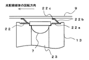
図5は、第1実施形態の対物レンズホルダ13に設けられる衝突防止部材22の構成を更に詳細に説明するための図で、図2におけるB−B断面の一部を示した図である。なお、図5においては、説明の便宜上、光記録媒体9も記載している。衝突防止部材22は、対物レンズホルダ13に固着するための固着部22aと、固着部22aから斜め上方に延びる傾斜部22bと、傾斜部22bから略水平方向(光記録媒体9の記録面9aと略平行な方向)に延びて、光記録媒体9と接触することがある接触部22cと、から成る。
FIG. 5 is a view for explaining the configuration of the
固着部22aには図示しないリブ穴が設けられており、このリブ穴に対物レンズホルダ13に立設されるリブ24(図2参照)を貫通することで、衝突防止部材22は対物レンズホルダ13に固定される。傾斜部22bは、光記録媒体9の回転方向(図5における矢印の方向)下流側に行くほど記録面9aに近づくように所定の傾きを持った状態で形成され、更に対物レンズ7より衝突防止部材22の接触部22cが高い位置となるように、その高さが調整される。固着部22a、傾斜部22b、及び接触部22cから成る衝突防止部材22は、例えば、ポリアセタール等の樹脂製の部材で一体的に形成される。
A rib hole (not shown) is provided in the fixing portion 22a, and the
衝突防止部材22は、上述のように対物レンズ7と光記録媒体9が衝突しないように設けられるが、この衝突防止部材22は、更に、光記録媒体9と衝突防止部材22とが接触することによって光記録媒体9が損傷するのを防止する光記録媒体損傷防止機構を有している。すなわち、衝突防止部材22に光記録媒体9が接触した場合、衝突防止部材22は、傾斜部22bの存在のために下方(対物レンズホルダ13側)に撓む。このため、衝突防止部材22と光記録媒体9とが接触した時の接触圧を低減し、光記録媒体9の損傷を防止する。
The
また、衝突防止部材22は、下方に撓むように構成されていることに加えて、傾斜部22cが光記録媒体9の回転方向と同方向に傾斜する構成としているために、衝突防止部材22と光記録媒体9が接触した状態で光記録媒体9が回転を続けても、光記録媒体9と衝突防止部材22との接触圧の上昇を抑制でき、光記録媒体9に過大な負荷がかかり難い。このため、光記録媒体9の損傷をより低確率とする。
Further, since the
なお、衝突防止部材22は、衝突防止部材22が光記録媒体9と接触して撓んだ場合にも光記録媒体9と対物レンズ7とが衝突することがないように、その高さの調整や部材の選定等が行われている。
The height of the
また、第1実施形態においては、衝突防止部材22を樹脂製の部材で形成する構成としているが、これに限られる趣旨ではない。すなわち、例えば、銅等の金属製の部材とする構成等としても構わない。
In the first embodiment, the
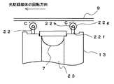
また、衝突防止部材22が、対物レンズホルダ側に撓む構成は、第1実施形態の構成のものに限定される趣旨ではなく、本発明の目的を逸脱しない範囲で種々の変形が可能である。すなわち、例えば、図6に示すような衝突防止部材22を設ける構成等としても構わない。図6における衝突防止部材22は、対物レンズホルダ13に固着するための固着部22aと、固着部22aから光記録媒体9の回転方向と同方向に延びて浮いた状態となっている平板部22dと、平板部22d上に設けられる球面形状の突起部22eと、から成る。
Further, the configuration in which the
この構成では、光記録媒体9が対物レンズ7と接近すると、突起部22eが光記録媒体9と接触し、平板部22dが下方に撓むことによって、光記録媒体9と衝突防止部材22が接触した時の衝撃を緩和する。そして、平板部22dが光記録媒体9の回転方向と同方向に延びて浮いた状態となっているために、衝突防止部材22と光記録媒体9が接触した状態で光記録媒体9が回転を続けても、光記録媒体9と衝突防止部材22との接触圧の上昇を抑制でき、光記録媒体9に過大な負荷がかかり難い。このため、光記録媒体9の損傷をより低確率とする。
In this configuration, when the
また、第1実施形態の他の構成として、図5における衝突防止部材22の傾斜部22bを光記録媒体9の回転方向と逆方向に傾ける構成等としても構わない。この場合でも、衝突防止部材22は光記録媒体9との接触時の衝撃を緩和することが可能である。そして、この場合には、光記録媒体9と衝突防止部材22とが接触した状態で光記録媒体9が回転を続けることで、光記録媒体9と衝突防止部材22との接触圧が増大し、光記録媒体9に大きな負荷がかかる可能性があるが、この点については、例えば、光記録媒体9と衝突防止部材22が接触した時点で対物レンズアクチュエータ11が対物レンズ7を光記録媒体9から離れる方向に即動かす構成とする等の対応策を講じることもできる。
Further, as another configuration of the first embodiment, a configuration in which the inclined portion 22b of the
次に、光ピックアップ装置1が備える対物レンズアクチュエータ11の第2実施形態について説明する。第2実施形態の対物レンズアクチュエータ11は、衝突防止部材22の構成を除いて第1実施形態の対物レンズアクチュエータ11と同様であるため、構成が異なる衝突防止部材22の構成についてのみ説明する。なお、第1実施形態と同一の部材については、同一の符号を付して説明する。
Next, a second embodiment of the
図7は、第2実施形態の対物レンズアクチュエータ11の衝突防止部材22周辺を拡大して示した概略断面図である。なお、説明の便宜上、光記録媒体9も記載している。図7に示すように、衝突防止部材22は、支持部22fと、支軸22hと、ローラ22gと、から成る。支持部22fは、ローラ22gを挟むように対向配置されて(図7においては紙面方向手前の支持部22fのみ見え、紙面方向奥側の支持部22fは見えていない)、対物レンズホルダ13に固設される。各支持部22fには、支軸22hを支える軸受け(図示せず)が設けられる。
FIG. 7 is an enlarged schematic cross-sectional view showing the periphery of the
支軸22hは、ローラ22gの中心を貫通しており、支持部22fに回転可能に保持される。ローラ22gは、光記録媒体9の回転方向を考慮して、図の矢印Cの方向に回転可能に配置される。このような構成される衝突防止部材22は、その高さが対物レンズ7の先端部より高く形成されているために、対物レンズ7と光記録媒体9との衝突を防止することができる。そして、第2実施形態の衝突防止部材22も第1実施形態の場合と同様に、光記録媒体9と衝突防止部材22とが接触することによって光記録媒体9が損傷するのを防止する光記録媒体損傷防止機構を有している。
The support shaft 22h passes through the center of the
すなわち、衝突防止部材22と光記録媒体9とが接触すると、衝突防止部材22の先端側に設けられるローラ22gが、光記録媒体9の回転に伴って矢印C方向に回転するために、衝突防止部材22と光記録媒体9との間に発生する摩擦が低減され、光記録媒体9と衝突防止部材22との摩擦による光記録媒体9の損傷を防止できる。
That is, when the
なお、衝突防止部材22にローラ22gを設けて、光記録媒体9の損傷を防止する構成は、第2実施形態の構成に限定される趣旨ではなく、本発明の目的を逸脱しない範囲で種々の変更が可能である。すなわち、衝突防止部材22を構成する支持部材22fの軸受け部分に弾性部材を配置して、光記録媒体9が衝突防止部材22に接触した時に、ローラ22gに貫通する支軸22hが対物レンズホルダ13側に沈み込むようにして、光記録媒体9と衝突防止部材22との接触による衝撃を緩和できる構成等としても構わない。
The configuration in which the
次に、光ピックアップ装置1が備える対物レンズアクチュエータ11の第3実施形態について説明する。第3実施形態の対物レンズアクチュエータ11は、衝突防止部材22の構成を除いて第1実施形態の対物レンズアクチュエータ11と同様であるため、構成が異なる衝突防止部材22の構成についてのみ説明する。なお、第1実施形態と同一の部材については、同一の符号を付して説明する。
Next, a third embodiment of the
図8は、第3実施形態の対物レンズアクチュエータ11の衝突防止部材22周辺を拡大して示した概略断面図である。なお、説明の便宜上、光記録媒体9も記載している。図8に示すように、衝突防止部材22は、支持部22fと、翼状に形成された先端部22iと、から成る。支持部22fは対物レンズホルダ13に固設され、支持部22fの先端側に翼状の部材(翼状に形成された先端部22i)が配置される。この際、翼状に形成された先端部22iは、光記録媒体の回転によっておきる空気の流れについて、光記録媒体9側に比べ対物レンズホルダ13側で空気の流れが速くなるように配置される。
FIG. 8 is an enlarged schematic cross-sectional view showing the periphery of the
このような構成される衝突防止部材22は、その高さが対物レンズ7の先端部より高く形成されているために、対物レンズ7と光記録媒体9との衝突を防止することができる。そして、第3実施形態の衝突防止部材22も第1実施形態の場合と同様に、光記録媒体9と衝突防止部材22とが接触することによって光記録媒体9が損傷するのを防止する光記録媒体損傷防止機構を有している。
Since the
すなわち、光記録媒体9の回転による空気の流れにより(図8中に矢印で示す)、対物レンズホルダ13が光記録媒体9に接近した場合には、衝突防止部材22の翼状の先端部22iは、空気密度の小さい対物レンズホルダ13方向に力を受ける。このため、光記録媒体9と衝突防止部材22は接触を回避することが可能となる。また、光記録媒体9と衝突防止部材22が接触するようなことがあっても、衝突防止部材22は対物レンズホルダ13方向に力を受けているために、光記録媒体9と衝突防止部材22が接触する時の衝撃は緩和される。従って、第3実施形態の衝突防止材22の存在により、光記録媒体9の損傷を防止することが可能となる。
That is, when the
なお、以上に示した実施形態における対物レンズアクチュエータ11は、対物レンズ7を保持する対物レンズホルダ13が、複数本のワイヤ(金属線)によってベース部材12に対して揺動可能に支持された、いわゆるワイヤ支持方式のアクチュエータとしているが、これに限定される趣旨ではなく、例えば、軸摺動型の二軸アクチュエータ等であっても、本発明はもちろん適用可能である。
In the
本発明は、対物レンズと、対物レンズの光軸方向に延びる空洞部を有し、対物レンズを空洞部の一方の端部側で保持する対物レンズホルダと、対物レンズホルダを磁力によって駆動するための磁気回路と、を備え、対物レンズホルダの対物レンズが保持される側には、対物レンズホルダから突出して対物レンズと光記録媒体との衝突を防止する衝突防止部材が設けられる対物レンズアクチュエータにおいて、衝突防止部材に、衝突防止部材と光記録媒体との接触による光記録媒体の損傷を防止する光記録媒体損傷防止機構を設けることとする。 The present invention has an objective lens, an objective lens holder having a cavity extending in the optical axis direction of the objective lens, and holding the objective lens on one end side of the cavity, and driving the objective lens holder by magnetic force An objective lens actuator provided with a collision preventing member that protrudes from the objective lens holder and prevents a collision between the objective lens and the optical recording medium on the side of the objective lens holder that holds the objective lens. The collision prevention member is provided with an optical recording medium damage prevention mechanism that prevents damage to the optical recording medium due to contact between the collision prevention member and the optical recording medium.
このため、衝突防止部材は、対物レンズと光記録媒体の衝突を防止するばかりではなく、衝突防止部材と光記録媒体との接触による光記録媒体の損傷を防止する機構をも有しているために、対物レンズの損傷を防止できるばかりでなく、光記録媒体の損傷も防止することが可能となる。 For this reason, the collision preventing member not only prevents the collision between the objective lens and the optical recording medium, but also has a mechanism for preventing damage to the optical recording medium due to contact between the collision preventing member and the optical recording medium. In addition, it is possible not only to prevent the objective lens from being damaged, but also to prevent the optical recording medium from being damaged.
また、衝突防止部材と光記録媒体とが接触した時に、衝突防止部材が対物レンズホルダ側に撓むように形成することで、光記録媒体と衝突防止部材とが接触した時の接触圧を低減でき、光記録媒体の損傷を防止することが可能となる。 Further, when the collision preventing member and the optical recording medium are in contact with each other, by forming the collision preventing member to bend toward the objective lens holder side, the contact pressure when the optical recording medium and the collision preventing member are in contact can be reduced. It is possible to prevent damage to the optical recording medium.
また、衝突防止部材の先端部にローラを設け、ローラを、衝突防止部材と光記録媒体とが接触した時に、光記録媒体の回転に伴って回転するように形成することで、光記録媒体と衝突防止部材との接触時の摩擦力を緩和できる。 Further, a roller is provided at the tip of the collision preventing member, and the roller is formed so as to rotate with the rotation of the optical recording medium when the collision preventing member and the optical recording medium come into contact with each other. The frictional force at the time of contact with the collision preventing member can be reduced.
また、衝突防止部材の先端部を翼状に形成し、翼状に形成される先端部を、光記録媒体の回転に伴う空気の流れによって対物レンズホルダ方向に力を受けるように配置することで、光記録媒体と衝突防止部材の接触を回避、又は両者が接触した場合の衝撃を緩和することができる。 In addition, the tip portion of the collision preventing member is formed in a wing shape, and the tip portion formed in the wing shape is disposed so as to receive a force in the direction of the objective lens holder by the air flow accompanying the rotation of the optical recording medium. The contact between the recording medium and the collision preventing member can be avoided, or the impact when both contact can be reduced.
また、上記の対物レンズアクチュエータを備える光ピックアップ装置は、対物レンズ及び光記録媒体の損傷が発生しにくいため情報の記録再生を安定して行うことが可能となる。 In addition, since the optical pickup device including the objective lens actuator described above is less likely to damage the objective lens and the optical recording medium, it is possible to stably record and reproduce information.
1 光ピックアップ装置
2 光源
7 対物レンズ
9 光記録媒体
9a 記録面
11 対物レンズアクチュエータ
22 衝突防止部材
22a 固着部
22b 傾斜部
22c 接触部
22g ローラ
22i 翼状に形成された先端部
23 空洞部
DESCRIPTION OF
Claims (9)
該光源から出射された光束を光記録媒体の記録面に集束する対物レンズと、
該対物レンズの光軸方向に延びる空洞部を有し、前記対物レンズを前記空洞部の前記光記録媒体側で保持する対物レンズホルダと、該対物レンズホルダを磁力によって駆動するための磁気回路と、を有し、前記対物レンズホルダの前記対物レンズが保持される側には、前記対物レンズホルダから突出して前記対物レンズと前記光記録媒体との衝突を防止する衝突防止部材が設けられる対物レンズアクチュエータと、
を備える光ピックアップ装置において、
前記衝突防止部材は、少なくとも2つ設けられて前記対物レンズを挟んで略対称な位置に配置され、また、前記対物レンズホルダと固着する固着部と、該固着部から前記光記録媒体に対して所定量傾いて前記光記録媒体の回転方向と同方向に延びる傾斜部と、該傾斜部から延び、前記記録面と略平行となる面を有して前記光記録媒体と接触することがある接触部と、から成って、前記光記録媒体と接触した際に、前記対物レンズホルダ側に撓むように形成されることを特徴とする光ピックアップ装置。 A light source;
An objective lens for focusing the light beam emitted from the light source on the recording surface of the optical recording medium;
An objective lens holder having a cavity extending in the optical axis direction of the objective lens, holding the objective lens on the optical recording medium side of the cavity, and a magnetic circuit for driving the objective lens holder by a magnetic force; An objective lens provided on the side of the objective lens holder on which the objective lens is held is provided with a collision preventing member that protrudes from the objective lens holder and prevents the objective lens and the optical recording medium from colliding with each other. An actuator,
In an optical pickup device comprising:
At least two collision preventing members are provided and arranged at substantially symmetrical positions with the objective lens interposed therebetween, and a fixing portion that is fixed to the objective lens holder, and the fixing portion to the optical recording medium A contact that may be in contact with the optical recording medium having an inclined portion that is inclined by a predetermined amount and extending in the same direction as the rotation direction of the optical recording medium, and a surface that extends from the inclined portion and is substantially parallel to the recording surface. And an optical pickup device formed to bend toward the objective lens holder when it comes into contact with the optical recording medium.
前記対物レンズホルダの前記対物レンズが保持される側には、前記対物レンズホルダから突出して前記対物レンズと前記光記録媒体との衝突を防止する衝突防止部材が設けられる対物レンズアクチュエータにおいて、
前記衝突防止部材に、前記衝突防止部材と前記光記録媒体との接触による前記光記録媒体の損傷を防止する光記録媒体損傷防止機構を設けたことを特徴とする対物レンズアクチュエータ。 An objective lens, an objective lens holder having a cavity extending in the optical axis direction of the objective lens, and holding the objective lens on the optical recording medium side of the cavity, and for driving the objective lens holder by magnetic force A magnetic circuit,
In the objective lens actuator provided with a collision preventing member that protrudes from the objective lens holder and prevents a collision between the objective lens and the optical recording medium, on the side of the objective lens holder where the objective lens is held,
An objective lens actuator comprising an optical recording medium damage prevention mechanism for preventing damage to the optical recording medium due to contact between the collision preventing member and the optical recording medium.
前記ローラは、前記衝突防止部材が前記光記録媒体と接触した時に、前記光記録媒体の回転に伴って回転するように形成されることを特徴とする請求項2に記載の対物レンズアクチュエータ。 A roller is provided at the tip of the collision preventing member,
3. The objective lens actuator according to claim 2, wherein the roller is formed to rotate along with the rotation of the optical recording medium when the collision preventing member comes into contact with the optical recording medium.
前記翼状に形成される先端部は、前記光記録媒体の回転に伴う空気の流れによって前記対物レンズホルダ方向に力を受けるように配置されることを特徴とする請求項2に記載の対物レンズアクチュエータ。 The tip of the collision preventing member is formed in a wing shape,
3. The objective lens actuator according to claim 2, wherein the tip formed in the wing shape is disposed so as to receive a force in the direction of the objective lens holder by an air flow accompanying rotation of the optical recording medium. .
Priority Applications (3)
| Application Number | Priority Date | Filing Date | Title |
|---|---|---|---|
| JP2006015975A JP2007200418A (en) | 2006-01-25 | 2006-01-25 | Objective lens actuator and optical pickup device provided with the same |
| US11/657,578 US20070171777A1 (en) | 2006-01-25 | 2007-01-25 | Objective lens actuator and optical pickup device having the same |
| DE102007003805A DE102007003805A1 (en) | 2006-01-25 | 2007-01-25 | Objective lens drive unit and the same optical pickup device |
Applications Claiming Priority (1)
| Application Number | Priority Date | Filing Date | Title |
|---|---|---|---|
| JP2006015975A JP2007200418A (en) | 2006-01-25 | 2006-01-25 | Objective lens actuator and optical pickup device provided with the same |
Publications (1)
| Publication Number | Publication Date |
|---|---|
| JP2007200418A true JP2007200418A (en) | 2007-08-09 |
Family
ID=38285422
Family Applications (1)
| Application Number | Title | Priority Date | Filing Date |
|---|---|---|---|
| JP2006015975A Pending JP2007200418A (en) | 2006-01-25 | 2006-01-25 | Objective lens actuator and optical pickup device provided with the same |
Country Status (3)
| Country | Link |
|---|---|
| US (1) | US20070171777A1 (en) |
| JP (1) | JP2007200418A (en) |
| DE (1) | DE102007003805A1 (en) |
Cited By (2)
| Publication number | Priority date | Publication date | Assignee | Title |
|---|---|---|---|---|
| JP2009176341A (en) * | 2008-01-22 | 2009-08-06 | Fujitsu Ten Ltd | Disk playback device |
| KR101742501B1 (en) * | 2017-01-09 | 2017-06-02 | 주식회사 나무가 | Dual camera |
Families Citing this family (4)
| Publication number | Priority date | Publication date | Assignee | Title |
|---|---|---|---|---|
| JP2008210458A (en) * | 2007-02-27 | 2008-09-11 | Funai Electric Co Ltd | Objective lens actuator and optical pickup device with same |
| JP4407744B2 (en) * | 2007-12-05 | 2010-02-03 | 船井電機株式会社 | Disk unit |
| JP2010192035A (en) * | 2009-02-18 | 2010-09-02 | Funai Electric Co Ltd | Objective lens actuator |
| JP6278858B2 (en) * | 2014-07-16 | 2018-02-14 | アルパイン株式会社 | Optical pickup device |
Family Cites Families (5)
| Publication number | Priority date | Publication date | Assignee | Title |
|---|---|---|---|---|
| JP3895471B2 (en) * | 1998-07-17 | 2007-03-22 | 富士通株式会社 | Lens actuator |
| JP2001285792A (en) * | 2000-03-30 | 2001-10-12 | Matsushita Electric Ind Co Ltd | Reproducing device, medium, information assembly, transmission medium and recording medium |
| JP4569800B2 (en) * | 2000-11-22 | 2010-10-27 | ソニー株式会社 | Optical pickup device and disk drive device |
| KR100772361B1 (en) * | 2001-06-08 | 2007-11-01 | 삼성전자주식회사 | Optical pickup apparatus |
| KR100493049B1 (en) * | 2003-02-18 | 2005-06-02 | 삼성전자주식회사 | Actuator for optical pickup and optical recording and/or reproducing apparatus employing it |
-
2006
- 2006-01-25 JP JP2006015975A patent/JP2007200418A/en active Pending
-
2007
- 2007-01-25 US US11/657,578 patent/US20070171777A1/en not_active Abandoned
- 2007-01-25 DE DE102007003805A patent/DE102007003805A1/en not_active Withdrawn
Cited By (2)
| Publication number | Priority date | Publication date | Assignee | Title |
|---|---|---|---|---|
| JP2009176341A (en) * | 2008-01-22 | 2009-08-06 | Fujitsu Ten Ltd | Disk playback device |
| KR101742501B1 (en) * | 2017-01-09 | 2017-06-02 | 주식회사 나무가 | Dual camera |
Also Published As
| Publication number | Publication date |
|---|---|
| US20070171777A1 (en) | 2007-07-26 |
| DE102007003805A1 (en) | 2007-09-06 |
Similar Documents
| Publication | Publication Date | Title |
|---|---|---|
| JP2007200418A (en) | Objective lens actuator and optical pickup device provided with the same | |
| US7543312B2 (en) | Optical pickup device | |
| JP2008034052A (en) | Objective lens actuator, and optical pickup device provided with the same | |
| EP2012318B1 (en) | Lens holder for optical pickup and optical pickup having same | |
| JP2007305179A (en) | Objective lens actuator and optical pickup incorporating it | |
| JP2009104740A (en) | Optical pickup | |
| JP4508134B2 (en) | Objective lens actuator and optical pickup device having the same | |
| JP2007157247A (en) | Objective lens actuator and information recording/reproducing device | |
| JP4543266B2 (en) | Objective lens actuator and optical pickup including the same | |
| JP4807398B2 (en) | Optical pickup | |
| JP2015028822A (en) | Optical pickup apparatus | |
| US8743668B2 (en) | Objective lens drive device and optical pickup | |
| JP2007149277A (en) | Objective lens actuator, and information recording and reproducing device | |
| JP2008152888A (en) | Objective lens driving device, assembling method for the same and optical disk apparatus | |
| US7872951B2 (en) | Actuator for optical pickup | |
| JP2007184064A (en) | Optical pickup device | |
| JP2009252331A (en) | Optical pickup apparatus and optical disk device | |
| JP2010020836A (en) | Optical pickup device and optical disk device | |
| JP2009245476A (en) | Objective lens actuator and optical disk device | |
| JP2002288857A (en) | Optical pickup actuator | |
| JP2005011531A (en) | Optical pickup device | |
| JP2008226326A (en) | Objective lens driving unit | |
| JP2009146531A (en) | Lens holder for optical pickup and optical pickup provided with the same | |
| JP2006260712A (en) | Objective lens driving device, optical pickup device, and optical disk device | |
| JP2009048724A (en) | Optical pickup |