JP2007198377A - Cooled cast component, cooled component manufacturing method, cast component surface cooling method, and gas turbine engine air foil structural element - Google Patents
Cooled cast component, cooled component manufacturing method, cast component surface cooling method, and gas turbine engine air foil structural element Download PDFInfo
- Publication number
- JP2007198377A JP2007198377A JP2007010928A JP2007010928A JP2007198377A JP 2007198377 A JP2007198377 A JP 2007198377A JP 2007010928 A JP2007010928 A JP 2007010928A JP 2007010928 A JP2007010928 A JP 2007010928A JP 2007198377 A JP2007198377 A JP 2007198377A
- Authority
- JP
- Japan
- Prior art keywords
- cooled
- passage
- turbine engine
- plenum
- outlet
- Prior art date
- Legal status (The legal status is an assumption and is not a legal conclusion. Google has not performed a legal analysis and makes no representation as to the accuracy of the status listed.)
- Pending
Links
Images


Classifications
-
- F—MECHANICAL ENGINEERING; LIGHTING; HEATING; WEAPONS; BLASTING
- F01—MACHINES OR ENGINES IN GENERAL; ENGINE PLANTS IN GENERAL; STEAM ENGINES
- F01D—NON-POSITIVE DISPLACEMENT MACHINES OR ENGINES, e.g. STEAM TURBINES
- F01D5/00—Blades; Blade-carrying members; Heating, heat-insulating, cooling or antivibration means on the blades or the members
- F01D5/12—Blades
- F01D5/14—Form or construction
- F01D5/18—Hollow blades, i.e. blades with cooling or heating channels or cavities; Heating, heat-insulating or cooling means on blades
- F01D5/186—Film cooling
-
- B—PERFORMING OPERATIONS; TRANSPORTING
- B22—CASTING; POWDER METALLURGY
- B22C—FOUNDRY MOULDING
- B22C9/00—Moulds or cores; Moulding processes
- B22C9/10—Cores; Manufacture or installation of cores
- B22C9/103—Multipart cores
-
- B—PERFORMING OPERATIONS; TRANSPORTING
- B22—CASTING; POWDER METALLURGY
- B22D—CASTING OF METALS; CASTING OF OTHER SUBSTANCES BY THE SAME PROCESSES OR DEVICES
- B22D7/00—Casting ingots, e.g. from ferrous metals
-
- F—MECHANICAL ENGINEERING; LIGHTING; HEATING; WEAPONS; BLASTING
- F01—MACHINES OR ENGINES IN GENERAL; ENGINE PLANTS IN GENERAL; STEAM ENGINES
- F01D—NON-POSITIVE DISPLACEMENT MACHINES OR ENGINES, e.g. STEAM TURBINES
- F01D5/00—Blades; Blade-carrying members; Heating, heat-insulating, cooling or antivibration means on the blades or the members
- F01D5/12—Blades
- F01D5/14—Form or construction
-
- F—MECHANICAL ENGINEERING; LIGHTING; HEATING; WEAPONS; BLASTING
- F02—COMBUSTION ENGINES; HOT-GAS OR COMBUSTION-PRODUCT ENGINE PLANTS
- F02C—GAS-TURBINE PLANTS; AIR INTAKES FOR JET-PROPULSION PLANTS; CONTROLLING FUEL SUPPLY IN AIR-BREATHING JET-PROPULSION PLANTS
- F02C7/00—Features, components parts, details or accessories, not provided for in, or of interest apart form groups F02C1/00 - F02C6/00; Air intakes for jet-propulsion plants
- F02C7/12—Cooling of plants
- F02C7/16—Cooling of plants characterised by cooling medium
- F02C7/18—Cooling of plants characterised by cooling medium the medium being gaseous, e.g. air
- F02C7/185—Cooling means for reducing the temperature of the cooling air or gas
-
- F—MECHANICAL ENGINEERING; LIGHTING; HEATING; WEAPONS; BLASTING
- F05—INDEXING SCHEMES RELATING TO ENGINES OR PUMPS IN VARIOUS SUBCLASSES OF CLASSES F01-F04
- F05D—INDEXING SCHEME FOR ASPECTS RELATING TO NON-POSITIVE-DISPLACEMENT MACHINES OR ENGINES, GAS-TURBINES OR JET-PROPULSION PLANTS
- F05D2230/00—Manufacture
- F05D2230/10—Manufacture by removing material
- F05D2230/12—Manufacture by removing material by spark erosion methods
-
- F—MECHANICAL ENGINEERING; LIGHTING; HEATING; WEAPONS; BLASTING
- F05—INDEXING SCHEMES RELATING TO ENGINES OR PUMPS IN VARIOUS SUBCLASSES OF CLASSES F01-F04
- F05D—INDEXING SCHEME FOR ASPECTS RELATING TO NON-POSITIVE-DISPLACEMENT MACHINES OR ENGINES, GAS-TURBINES OR JET-PROPULSION PLANTS
- F05D2230/00—Manufacture
- F05D2230/10—Manufacture by removing material
- F05D2230/13—Manufacture by removing material using lasers
-
- F—MECHANICAL ENGINEERING; LIGHTING; HEATING; WEAPONS; BLASTING
- F05—INDEXING SCHEMES RELATING TO ENGINES OR PUMPS IN VARIOUS SUBCLASSES OF CLASSES F01-F04
- F05D—INDEXING SCHEME FOR ASPECTS RELATING TO NON-POSITIVE-DISPLACEMENT MACHINES OR ENGINES, GAS-TURBINES OR JET-PROPULSION PLANTS
- F05D2230/00—Manufacture
- F05D2230/20—Manufacture essentially without removing material
- F05D2230/21—Manufacture essentially without removing material by casting
- F05D2230/211—Manufacture essentially without removing material by casting by precision casting, e.g. microfusing or investment casting
-
- F—MECHANICAL ENGINEERING; LIGHTING; HEATING; WEAPONS; BLASTING
- F05—INDEXING SCHEMES RELATING TO ENGINES OR PUMPS IN VARIOUS SUBCLASSES OF CLASSES F01-F04
- F05D—INDEXING SCHEME FOR ASPECTS RELATING TO NON-POSITIVE-DISPLACEMENT MACHINES OR ENGINES, GAS-TURBINES OR JET-PROPULSION PLANTS
- F05D2230/00—Manufacture
- F05D2230/90—Coating; Surface treatment
-
- F—MECHANICAL ENGINEERING; LIGHTING; HEATING; WEAPONS; BLASTING
- F05—INDEXING SCHEMES RELATING TO ENGINES OR PUMPS IN VARIOUS SUBCLASSES OF CLASSES F01-F04
- F05D—INDEXING SCHEME FOR ASPECTS RELATING TO NON-POSITIVE-DISPLACEMENT MACHINES OR ENGINES, GAS-TURBINES OR JET-PROPULSION PLANTS
- F05D2240/00—Components
- F05D2240/10—Stators
- F05D2240/12—Fluid guiding means, e.g. vanes
- F05D2240/121—Fluid guiding means, e.g. vanes related to the leading edge of a stator vane
-
- F—MECHANICAL ENGINEERING; LIGHTING; HEATING; WEAPONS; BLASTING
- F05—INDEXING SCHEMES RELATING TO ENGINES OR PUMPS IN VARIOUS SUBCLASSES OF CLASSES F01-F04
- F05D—INDEXING SCHEME FOR ASPECTS RELATING TO NON-POSITIVE-DISPLACEMENT MACHINES OR ENGINES, GAS-TURBINES OR JET-PROPULSION PLANTS
- F05D2240/00—Components
- F05D2240/20—Rotors
- F05D2240/30—Characteristics of rotor blades, i.e. of any element transforming dynamic fluid energy to or from rotational energy and being attached to a rotor
- F05D2240/303—Characteristics of rotor blades, i.e. of any element transforming dynamic fluid energy to or from rotational energy and being attached to a rotor related to the leading edge of a rotor blade
-
- F—MECHANICAL ENGINEERING; LIGHTING; HEATING; WEAPONS; BLASTING
- F05—INDEXING SCHEMES RELATING TO ENGINES OR PUMPS IN VARIOUS SUBCLASSES OF CLASSES F01-F04
- F05D—INDEXING SCHEME FOR ASPECTS RELATING TO NON-POSITIVE-DISPLACEMENT MACHINES OR ENGINES, GAS-TURBINES OR JET-PROPULSION PLANTS
- F05D2260/00—Function
- F05D2260/20—Heat transfer, e.g. cooling
- F05D2260/204—Heat transfer, e.g. cooling by the use of microcircuits
-
- F—MECHANICAL ENGINEERING; LIGHTING; HEATING; WEAPONS; BLASTING
- F05—INDEXING SCHEMES RELATING TO ENGINES OR PUMPS IN VARIOUS SUBCLASSES OF CLASSES F01-F04
- F05D—INDEXING SCHEME FOR ASPECTS RELATING TO NON-POSITIVE-DISPLACEMENT MACHINES OR ENGINES, GAS-TURBINES OR JET-PROPULSION PLANTS
- F05D2300/00—Materials; Properties thereof
- F05D2300/60—Properties or characteristics given to material by treatment or manufacturing
- F05D2300/611—Coating
-
- Y—GENERAL TAGGING OF NEW TECHNOLOGICAL DEVELOPMENTS; GENERAL TAGGING OF CROSS-SECTIONAL TECHNOLOGIES SPANNING OVER SEVERAL SECTIONS OF THE IPC; TECHNICAL SUBJECTS COVERED BY FORMER USPC CROSS-REFERENCE ART COLLECTIONS [XRACs] AND DIGESTS
- Y02—TECHNOLOGIES OR APPLICATIONS FOR MITIGATION OR ADAPTATION AGAINST CLIMATE CHANGE
- Y02T—CLIMATE CHANGE MITIGATION TECHNOLOGIES RELATED TO TRANSPORTATION
- Y02T50/00—Aeronautics or air transport
- Y02T50/60—Efficient propulsion technologies, e.g. for aircraft
Abstract
Description
本発明は、高温の構成部品の冷却に関する。より詳細には、本発明はガスタービンエンジンの構成部品のフィルム冷却に関する。 The present invention relates to cooling of hot components. More particularly, the present invention relates to film cooling of gas turbine engine components.
航空宇宙産業においては、ガスタービンエンジンの構成部品などの構成部品の冷却に関して充分に発達した技術が存在する。例示的な構成部品としては、ガスタービンエンジンのブレードおよびベーンが挙げられる。例示的なブレードおよびベーンは、ブレードまたはベーンのエアフォイルを通流し、エアフォイル表面の冷却孔から流出する空気によって冷却される。この冷却機構には、空気がエアフォイルを通流する直接冷却、および空気がエアフォイルから流出した後に下流のエアフォイル表面の近傍に沿って流れるフィルム冷却が含まれる。 In the aerospace industry, there are well developed technologies for cooling components such as gas turbine engine components. Exemplary components include gas turbine engine blades and vanes. Exemplary blades and vanes flow through the blade or vane airfoil and are cooled by air exiting through cooling holes in the airfoil surface. This cooling mechanism includes direct cooling where air flows through the airfoil and film cooling which flows along the vicinity of the downstream airfoil surface after the air flows out of the airfoil.
有効なフィルム冷却をもたらすためには、フィルム冷却用空気が流出する前に熱を最小限に抑えることが望ましい。これは、第1の空気流を用いて、第2の空気流が通流する通路を冷却するものであり、したがって、第2の空気流は、第1の空気流を用いない場合と比べて、より低温で流出することとなる。 In order to provide effective film cooling, it is desirable to minimize heat before the film cooling air exits. This uses the first air flow to cool the passage through which the second air flow passes. Therefore, the second air flow is compared with the case where the first air flow is not used. It will flow out at a lower temperature.
したがって、本発明の1つの態様は、外側表面を有する被冷却鋳造部分を含む。冷却通路システムは、少なくとも1つの入口ポートから複数の出口ポートまで延びている。この通路システムは、前記複数の出口のうち少なくとも第1の出口まで延びるとともに、少なくとも1つの支柱部分(ポスト)を取り囲む第1の通路を含む。また、この通路システムは、前記複数の出口のうち少なくとも第2の出口まで延びるとともに、前記少なくとも1つの支柱部分を貫通する第2の通路を含む。 Accordingly, one aspect of the present invention includes a cooled cast portion having an outer surface. The cooling passage system extends from at least one inlet port to a plurality of outlet ports. The passage system includes a first passage that extends to at least a first outlet of the plurality of outlets and surrounds at least one post portion (post). The passage system includes a second passage that extends to at least a second outlet of the plurality of outlets and penetrates the at least one strut portion.
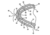
図1は、概略的なガスタービンエンジンのベーン20を示している。例示的なベーンは、単一の鋳造物から形成されるとともに、内側プラットフォーム24と外側シュラウド26との間で翼幅(スパン)方向に延びるエアフォイル22を備える。例示的なプラットフォームおよびシュラウドは、環状のセグメントであり、これらのプラットフォームおよびシュラウドのエッジをそれぞれ互いに付け合わせ、シールすることにより円周方向のベーンの列が形成される。エアフォイル22は、前縁30および後縁32を有する。前縁と後縁との間で正圧側34および負圧側36が流れ方向に延びている。
FIG. 1 shows a schematic gas
例示的なエアフォイルは、プラットフォームおよびシュラウドの少なくとも一方における1つまたは複数のポート38を通って、エアフォイルに沿った孔の列から流出する空気流により冷却される。図1の例示的なエアフォイルは、翼幅方向に整列した一連の第1の孔/出口40および第2の孔/出口42を備え、第1の孔/出口40は、前縁30あるいはその近傍に配列され、第2の孔/出口42は、前縁30のすぐ下流側で正圧側34に沿って配列されている。エアフォイルは、正圧側、負圧側および後縁の出口(図示せず)に沿った付加的なフィルム冷却孔(図示せず)など他の孔を備えていてもよい。
The exemplary airfoil is cooled by an air flow exiting from the row of holes along the airfoil through one or
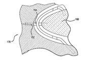
図2は、エアフォイルの前縁30近傍の領域を図示している。このエアフォイルは、翼幅方向に延びる前縁側供給通路54の境界をなすとともに局所的に内側表面52を有する壁部50を備える。この壁部には、主要部56を備えた冷却プレナム55が前縁に亘って配設されている。出口42は、対応する正圧側の出口通路57の端部におけるプレナム55の出口である。対応する翼幅方向の一連の入口58により、対応する入口通路59から空気がプレナムに供給される。したがって、第1の空気流60は、入口58からプレナム55内に流入して出口42から流出し、正圧側34に沿って下流方向に流れる。したがって、第1の空気流60は、プレナムに隣接する壁部50を直接冷却するとともに、出口42の下流における正圧側34に沿って壁部50にフィルム冷却をもたらす。
FIG. 2 illustrates a region near the leading
前縁30付近の冷却は特に重要である。付加的な冷却をもたらすように、一連の出口通路62が、供給通路54に沿って、対応する入口64から出口40まで直接延びている。通路62により、空気流61が導かれて出口40から流出する。通路62は、プレナムの主要部56の支柱部分(ポスト)66を貫通して延びている。支柱部分66は、壁部50の内側部分と外側部分との間に亘っている。各支柱部分の外周面70は、空気流60によって冷却される。この冷却により、第2の空気流61が入口64と出口40の間を通過する際に第2の空気流61の加熱が制限される。したがって、空気流61は出口40から流出するときには比較的低温となっており、これにより、特に向上したフィルム冷却効果がもたらされる。
Cooling near the leading
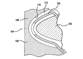
ベーン20や他の被冷却構成部品は、インベストメント鋳造によって形成され得る。例示的な工程では、耐熱金属コア(RMC)100(図3)を用いて、プレナム55を鋳造し、セラミックのフィードコア(feed core)102を用いて、供給通路54を鋳造する。図3では、模型用金型104内でフィードコア102に組み付けられたRMC100が図示されている。例示的な金型104は、一対の金型半部つまりプル106,108を含み、この半部は、コアアッセンブリを覆って犠牲模型材料(例えば、天然ろうまたは合成ろう)を成形するキャビティ112を画定するように位置決めされた内側面110を有する。成形後、模型は、金型から取り外され、シェルで覆われる(例えば、複数回のスタッコイングにより)。次いで、溶融金属を鋳込む型を形成するように、シェルからろうを除去して、シェルを焼成する。鋳込後、シェルおよびコアアッセンブリが除去される(例えば、シェルを機械的に壊し、コアアッセンブリを化学的に除去する)。機械加工や保護コーティングなど、鋳造物に付加的な処理を施してもよい。
The
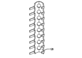
図4〜図7には、例示的なRMC(耐熱金属コア)100をさらに詳細に図示している。RMC100は、第1の翼幅方向端部122から第2の翼幅方向端部124まで延びる本体120を有する。本体120は、プレナムの主要部56を鋳造する形状を有する。したがって、本体120には、支柱部66を鋳造する形状を備えて配設された開口部126が翼幅方向に配列されている。支柱部形成用の開口部126は、内側コア表面128と外側コア表面130との間に延びている。本体120は、第1の縁部140を有し、この縁部140から延びるタブ142が翼幅方向に配列されている。また、本体120は、第2の縁部144を有し、この縁部144から延びるタブ146が翼幅方向に配列されている。タブ142の近接部分は、プレナムの出口通路57を鋳造するように構成かつ配設される。タブ142の遠位部分は、金型に対してRMCを配置するように、対応する金型のコンパートメント内に受容される。その後、タブ142の遠位部分は、鋳造中にRMC100を保持/配置するようにシェル内に埋め込まれてもよい。タブ146の近位部分は、入口通路59を鋳造するように構成かつ配設される。タブ146の遠位部分は、フィードコア102に対してRMC100を配置かつ固定するため、フィードコア102における1つまたは複数の対応するコンパートメント内に受容されるように構成されている。
4-7 illustrate an exemplary RMC (refractory metal core) 100 in more detail. The RMC 100 has a
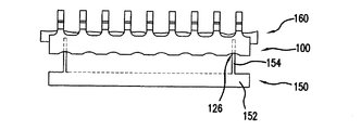
図8では、通路62および出口孔40をドリル加工する前の、鋳造したままの(鋳放し)状態の部品が図示されている。例示的なドリル加工としては、機械ドリル加工、レーザドリル加工、放電加工(EDM)などが挙げられる。別の実施例として、通路62を鋳造してもよい。一実施例として、図9および図10に、通路62および出口40を形成する第2のRMC150を示す。例示的なRMC150は、くし形状を有しており、背部152と、この背部から延びるとともに翼幅方向に配列された歯部154と、を有する。歯部154の近位部分は、第1のRMC100の開口部126を通るように構成かつ配置されている。また、歯部154の遠位部分は、セラミックのフィードコア160(図10;またはフィードコア102と同様であってもよい)に受容されるように構成かつ配置されている。例示的なコアの組み立て手順においては、まず、第1のRMC100をフィードコア160に組み付ける。次いで、第1のRMC100の開口部126を通して、第2のRMC150の歯部154をフィードコア160内の1つまたは複数のスロットまたは他のブラインドコンパートメントに挿入して、第2のRMC150をフィードコアに組み付ける。その後、このコアアッセンブリを模型成形用金型170内に配置する。
FIG. 8 shows the part as-cast (as cast) before drilling the
本発明の1つまたは複数の実施態様について述べた。しかし、本発明の精神ならびに範囲を逸脱することなく、種々の修正がなされることを理解されたい。例えば、基準となる構成部品の再設計を実施する場合に、基準の構成部品の細部によって、特定の実施の細部に影響が及ぶことがある。例示的な支柱部は、環状の断面形状を有しており、その周りを取り囲んでいる隣接のプレナム壁部から間隔を隔てているが、他の形態であってもよい。同様に、支柱部を貫通する孔についても種々の形状や配列が可能である。したがって、他の実施態様も添付の特許請求の範囲の範囲内にある。 One or more embodiments of the present invention have been described. However, it should be understood that various modifications can be made without departing from the spirit and scope of the invention. For example, when redesigning a reference component, the details of the reference component may affect the details of the particular implementation. The exemplary strut has an annular cross-sectional shape and is spaced from an adjacent plenum wall surrounding it, but may take other forms. Similarly, various shapes and arrangements are possible for the holes penetrating the support column. Accordingly, other embodiments are within the scope of the appended claims.
Claims (20)
外側表面と、
少なくとも1つの入口ポートから複数の出口ポートまで延びる冷却通路システムと、
を含み、
前記通路システムは、
前記複数の出口のうち少なくとも第1の出口まで延びるとともに、少なくとも1つの支柱部分を取り囲む第1の通路と、
前記複数の出口のうち少なくとも第2の出口まで延びるとともに、前記少なくとも1つの支柱部分を貫通する第2の通路と、
を含む被冷却鋳造部品。 A cooled cast part,
An outer surface;
A cooling passage system extending from at least one inlet port to a plurality of outlet ports;
Including
The passage system includes:
A first passage extending to at least a first outlet of the plurality of outlets and surrounding at least one strut portion;
A second passage extending to at least a second outlet of the plurality of outlets and penetrating the at least one strut portion;
Including cooled casting parts.
ガスタービンエンジンのベーン、
ガスタービンエンジンのブレード、
ガスタービンエンジンのブレード外側エアシール、
ガスタービンエンジンの燃焼器の構成部品、
のうちの1つであることを特徴とする請求項1に記載の被冷却鋳造部品。 The parts are
Gas turbine engine vanes,
Gas turbine engine blades,
Gas turbine engine blade outer air seal,
Gas turbine engine combustor components,
The to-be-cooled cast part according to claim 1, which is one of the following.
前記第1の通路は、前縁側冷却プレナムであることを特徴とする請求項1に記載の被冷却鋳造部品。 The component is an airfoil component of a turbine engine;
The to-be-cooled cast component according to claim 1, wherein the first passage is a leading edge side cooling plenum.
複数の供給通路を形成することと、
前記供給通路の少なくとも1つと連通するとともに、複数の支柱部分を有するプレナムを形成することと、
前記複数の支柱部分を貫通するとともに、少なくとも1つの供給通路と連通する出口通路を形成することと、
を含む被冷却部品製造方法。 A method for producing a cooled part, comprising:
Forming a plurality of supply passages;
Forming a plenum in communication with at least one of the supply passages and having a plurality of strut portions;
Forming an outlet passage that penetrates the plurality of strut portions and communicates with at least one supply passage;
A method for manufacturing a cooled part including:
前記コアアッセンブリを破壊的に取り外すことと、
を含み、
前記コアアッセンブリの第1の部分により、基本的に前記供給通路が形成され、
前記コアアッセンブリの第2の部分により、前記支柱部分を取り囲む前記プレナムの少なくとも一部分が形成されることを特徴とする請求項7に記載の被冷却部品製造方法。 Casting over the core assembly;
Destructively removing the core assembly;
Including
The supply passage is basically formed by the first part of the core assembly,
The method for manufacturing a cooled part according to claim 7, wherein the second part of the core assembly forms at least a part of the plenum surrounding the column part.
前記プレナムの形成が、前縁側プレナムとして前記プレナムを位置決めすることを含むことを特徴とする請求項7に記載の被冷却部品製造方法。 Used for casting turbine engine airfoil components,
The method for manufacturing a cooled part according to claim 7, wherein forming the plenum includes positioning the plenum as a leading edge side plenum.
第1の端部および第2の端部と、
前縁および後縁と、
正圧側および負圧側と、
複数の第1の出口を有する前縁側プレナムを含んだ内部冷却通路システムと、
を有するエアフォイルを備え、さらに、
前記前縁側プレナムを横切って延びる少なくとも1つの支柱部分と、
前記少なくとも1つの支柱部分を貫通して少なくとも1つの第2の出口まで延びる少なくとも1つの出口通路と、
を備えることを特徴とするガスタービンエンジンエアフォイル構成要素。 An airfoil component of a gas turbine engine,
A first end and a second end;
With leading and trailing edges,
Positive pressure side and negative pressure side,
An internal cooling passage system including a leading edge plenum having a plurality of first outlets;
An airfoil having,
At least one strut portion extending across the leading edge plenum;
At least one outlet passage extending through the at least one strut portion to at least one second outlet;
A gas turbine engine airfoil component comprising:
前記第1の端部および第2の端部は、内側シュラウドセグメントおよび外側シュラウドセグメントにそれぞれ位置することを特徴とする請求項14に記載のガスタービンエンジンエアフォイル構成要素。 The component is a vane;
The gas turbine engine airfoil component of claim 14, wherein the first end and the second end are located in an inner shroud segment and an outer shroud segment, respectively.
前記鋳造部品のチャンバ内の1つまたは複数の支柱部分の周囲を通って、1つまたは複数の第1の出口から流出するように、前記チャンバ内を通して第1の冷却流を流すことと、
1つまたは複数の第2の出口から流出し、前記部品の表面に沿ってフィルム冷却をもたらすように、前記1つまたは複数の支柱部分を通して第2の冷却流を流すことと、
を含む方法。 A method for cooling the surface of a cast part, comprising:
Flowing a first cooling flow through the chamber to flow out of one or more first outlets around one or more strut portions in the chamber of the cast part;
Flowing a second cooling flow through the one or more strut portions to exit from the one or more second outlets and provide film cooling along the surface of the part;
Including methods.
前記第2の冷却流が通流する複数の支柱部分を含むことを特徴とする請求項17に記載の鋳造部品表面冷却方法。 The chamber is a plenum along the leading edge portion of the airfoil;
The casting part surface cooling method according to claim 17, further comprising a plurality of strut portions through which the second cooling flow passes.
Applications Claiming Priority (1)
| Application Number | Priority Date | Filing Date | Title |
|---|---|---|---|
| US11/340,911 US7322795B2 (en) | 2006-01-27 | 2006-01-27 | Firm cooling method and hole manufacture |
Publications (2)
| Publication Number | Publication Date |
|---|---|
| JP2007198377A true JP2007198377A (en) | 2007-08-09 |
| JP2007198377A5 JP2007198377A5 (en) | 2008-03-27 |
Family
ID=37873107
Family Applications (1)
| Application Number | Title | Priority Date | Filing Date |
|---|---|---|---|
| JP2007010928A Pending JP2007198377A (en) | 2006-01-27 | 2007-01-22 | Cooled cast component, cooled component manufacturing method, cast component surface cooling method, and gas turbine engine air foil structural element |
Country Status (7)
| Country | Link |
|---|---|
| US (1) | US7322795B2 (en) |
| EP (1) | EP1813775B1 (en) |
| JP (1) | JP2007198377A (en) |
| KR (1) | KR20070078685A (en) |
| CN (1) | CN101008327A (en) |
| SG (1) | SG134205A1 (en) |
| TW (1) | TW200728594A (en) |
Families Citing this family (39)
| Publication number | Priority date | Publication date | Assignee | Title |
|---|---|---|---|---|
| US7625179B2 (en) * | 2006-09-13 | 2009-12-01 | United Technologies Corporation | Airfoil thermal management with microcircuit cooling |
| US8066052B2 (en) * | 2007-06-07 | 2011-11-29 | United Technologies Corporation | Cooled wall thickness control |
| US20090314748A1 (en) * | 2008-06-21 | 2009-12-24 | United Technologies Corporation | Ultrasonic assisted electrodischarge machining |
| US8157527B2 (en) * | 2008-07-03 | 2012-04-17 | United Technologies Corporation | Airfoil with tapered radial cooling passage |
| US8572844B2 (en) * | 2008-08-29 | 2013-11-05 | United Technologies Corporation | Airfoil with leading edge cooling passage |
| US8303252B2 (en) * | 2008-10-16 | 2012-11-06 | United Technologies Corporation | Airfoil with cooling passage providing variable heat transfer rate |
| US8109725B2 (en) * | 2008-12-15 | 2012-02-07 | United Technologies Corporation | Airfoil with wrapped leading edge cooling passage |
| US20130078418A1 (en) * | 2011-09-23 | 2013-03-28 | General Electric Company | Components with cooling channels and methods of manufacture |
| US8967957B2 (en) * | 2011-11-03 | 2015-03-03 | General Electric Company | Rotating airfoil component of a turbomachine |
| US9249670B2 (en) * | 2011-12-15 | 2016-02-02 | General Electric Company | Components with microchannel cooling |
| CH706090A1 (en) * | 2012-02-17 | 2013-08-30 | Alstom Technology Ltd | A method for manufacturing a near-surface cooling passage in a thermally highly stressed component and component with such a channel. |
| US20130280093A1 (en) * | 2012-04-24 | 2013-10-24 | Mark F. Zelesky | Gas turbine engine core providing exterior airfoil portion |
| US10259039B2 (en) | 2013-02-12 | 2019-04-16 | United Technologies Corporation | Gas turbine engine component cooling passage and space casting core |
| EP2971667A4 (en) | 2013-03-15 | 2016-12-14 | United Technologies Corp | Gas turbine engine shaped film cooling hole |
| CN103452595A (en) * | 2013-09-25 | 2013-12-18 | 青岛科技大学 | Novel air film hole with improved cooling efficiency |
| US20160222795A1 (en) * | 2013-10-23 | 2016-08-04 | United Technologies Corporation | Turbine Airfoil Cooling Core Exit |
| US9061349B2 (en) * | 2013-11-07 | 2015-06-23 | Siemens Aktiengesellschaft | Investment casting method for gas turbine engine vane segment |
| EP3124135B1 (en) * | 2014-03-28 | 2019-05-29 | IHI Corporation | CASTING MOLD, METHOD OF MANUFACTURING SAME, Ti-Al ALLOY CAST PRODUCT, AND METHOD OF CASTING SAME |
| US10329921B2 (en) | 2014-10-24 | 2019-06-25 | United Technologies Corporation | Cooling configuration for a component |
| US10578305B2 (en) | 2014-11-03 | 2020-03-03 | Siemens Aktiengesellschaft | Bruner assembly |
| US10099276B2 (en) | 2015-12-17 | 2018-10-16 | General Electric Company | Method and assembly for forming components having an internal passage defined therein |
| US10137499B2 (en) | 2015-12-17 | 2018-11-27 | General Electric Company | Method and assembly for forming components having an internal passage defined therein |
| US10099283B2 (en) | 2015-12-17 | 2018-10-16 | General Electric Company | Method and assembly for forming components having an internal passage defined therein |
| US10118217B2 (en) | 2015-12-17 | 2018-11-06 | General Electric Company | Method and assembly for forming components having internal passages using a jacketed core |
| US9579714B1 (en) | 2015-12-17 | 2017-02-28 | General Electric Company | Method and assembly for forming components having internal passages using a lattice structure |
| US9987677B2 (en) | 2015-12-17 | 2018-06-05 | General Electric Company | Method and assembly for forming components having internal passages using a jacketed core |
| US9968991B2 (en) | 2015-12-17 | 2018-05-15 | General Electric Company | Method and assembly for forming components having internal passages using a lattice structure |
| US10150158B2 (en) | 2015-12-17 | 2018-12-11 | General Electric Company | Method and assembly for forming components having internal passages using a jacketed core |
| US10099284B2 (en) | 2015-12-17 | 2018-10-16 | General Electric Company | Method and assembly for forming components having a catalyzed internal passage defined therein |
| US10046389B2 (en) | 2015-12-17 | 2018-08-14 | General Electric Company | Method and assembly for forming components having internal passages using a jacketed core |
| US10335853B2 (en) | 2016-04-27 | 2019-07-02 | General Electric Company | Method and assembly for forming components using a jacketed core |
| US10286450B2 (en) | 2016-04-27 | 2019-05-14 | General Electric Company | Method and assembly for forming components using a jacketed core |
| US20170335692A1 (en) * | 2016-05-20 | 2017-11-23 | United Technologies Corporation | Refractory metal core and components formed thereby |
| US10323569B2 (en) | 2016-05-20 | 2019-06-18 | United Technologies Corporation | Core assemblies and gas turbine engine components formed therefrom |
| US20180238175A1 (en) * | 2017-02-21 | 2018-08-23 | General Electric Company | Method and Device for Retaining Position of a Consumable Core |
| US20190218917A1 (en) | 2018-01-17 | 2019-07-18 | General Electric Company | Engine component with set of cooling holes |
| CN112145234B (en) * | 2020-09-24 | 2021-08-20 | 大连理工大学 | Omega type gyration chamber plywood cooling structure |
| CN112643298B (en) * | 2020-12-25 | 2021-07-23 | 浙江燃创透平机械股份有限公司 | Flow guide pipe of gas turbine stationary blade in heat pump system and preparation method |
| US11572803B1 (en) * | 2022-08-01 | 2023-02-07 | General Electric Company | Turbine airfoil with leading edge cooling passage(s) coupled via plenum to film cooling holes, and related method |
Family Cites Families (7)
| Publication number | Priority date | Publication date | Assignee | Title |
|---|---|---|---|---|
| BE755567A (en) * | 1969-12-01 | 1971-02-15 | Gen Electric | FIXED VANE STRUCTURE, FOR GAS TURBINE ENGINE AND ASSOCIATED TEMPERATURE ADJUSTMENT ARRANGEMENT |
| US5405242A (en) * | 1990-07-09 | 1995-04-11 | United Technologies Corporation | Cooled vane |
| US5290143A (en) * | 1992-11-02 | 1994-03-01 | Allied Signal | Bicast vane and shroud rings |
| US5779437A (en) * | 1996-10-31 | 1998-07-14 | Pratt & Whitney Canada Inc. | Cooling passages for airfoil leading edge |
| US5931638A (en) * | 1997-08-07 | 1999-08-03 | United Technologies Corporation | Turbomachinery airfoil with optimized heat transfer |
| US7281895B2 (en) * | 2003-10-30 | 2007-10-16 | Siemens Power Generation, Inc. | Cooling system for a turbine vane |
| US6929054B2 (en) * | 2003-12-19 | 2005-08-16 | United Technologies Corporation | Investment casting cores |
-
2006
- 2006-01-27 US US11/340,911 patent/US7322795B2/en active Active
- 2006-06-02 TW TW095119739A patent/TW200728594A/en unknown
- 2006-07-11 KR KR1020060064901A patent/KR20070078685A/en active IP Right Grant
- 2006-08-07 SG SG200605326-8A patent/SG134205A1/en unknown
-
2007
- 2007-01-22 JP JP2007010928A patent/JP2007198377A/en active Pending
- 2007-01-24 EP EP07250282.6A patent/EP1813775B1/en active Active
- 2007-01-26 CN CNA2007100061734A patent/CN101008327A/en active Pending
Also Published As
| Publication number | Publication date |
|---|---|
| TW200728594A (en) | 2007-08-01 |
| US20070177975A1 (en) | 2007-08-02 |
| CN101008327A (en) | 2007-08-01 |
| EP1813775A2 (en) | 2007-08-01 |
| EP1813775B1 (en) | 2016-07-06 |
| EP1813775A3 (en) | 2010-11-03 |
| SG134205A1 (en) | 2007-08-29 |
| KR20070078685A (en) | 2007-08-01 |
| US7322795B2 (en) | 2008-01-29 |
Similar Documents
| Publication | Publication Date | Title |
|---|---|---|
| JP2007198377A (en) | Cooled cast component, cooled component manufacturing method, cast component surface cooling method, and gas turbine engine air foil structural element | |
| EP1849965B1 (en) | Vane platform cooling | |
| US7625178B2 (en) | High effectiveness cooled turbine blade | |
| EP1927414B1 (en) | RMC-Defined tip blowing slots for turbine blades | |
| US8292581B2 (en) | Air cooled turbine blades and methods of manufacturing | |
| US9103225B2 (en) | Blade outer air seal with cored passages | |
| JP4416287B2 (en) | Internal cooling airfoil component and cooling method | |
| EP1010859B1 (en) | Cooling system for a turbine airfoil having a three pass cooling circuit | |
| JP2007061902A (en) | Method and apparatus for manufacturing pattern for investment casting, and casting core | |
| JP2004308659A (en) | Turbine element and method for manufacturing turbine blade | |
| JP2007170379A (en) | Turbine engine blade and its cooling method | |
| JP2007198377A5 (en) | ||
| JP6613803B2 (en) | Blade, gas turbine provided with the blade, and method of manufacturing the blade | |
| JP2007132342A (en) | Turbine engine component, refractory metal core, and airfoil part molding step | |
| KR20090127913A (en) | Guide vane duct element for a guide vane assembly of a gas turbine engine | |
| JP2008019861A (en) | Turbine engine component | |
| EP1923152B1 (en) | Trubine blade casting method | |
| JP2007170392A (en) | Airfoil for rotor blade, and turbine blade | |
| JP4208504B2 (en) | Method and apparatus for extending the useful life of gas turbine engine airfoils | |
| WO2014108318A1 (en) | Blade for a turbomachine | |
| US6619912B2 (en) | Turbine blade or vane | |
| EP2752554A1 (en) | Blade for a turbomachine | |
| US10024190B1 (en) | Apparatus and process for forming an air cooled turbine airfoil with a cooling air channel and discharge slot in a thin wall | |
| US11885230B2 (en) | Airfoil with internal crossover passages and pin array |
Legal Events
| Date | Code | Title | Description |
|---|---|---|---|
| A521 | Written amendment |
Free format text: JAPANESE INTERMEDIATE CODE: A523 Effective date: 20080213 |
|
| A871 | Explanation of circumstances concerning accelerated examination |
Free format text: JAPANESE INTERMEDIATE CODE: A871 Effective date: 20080213 |
|
| A975 | Report on accelerated examination |
Free format text: JAPANESE INTERMEDIATE CODE: A971005 Effective date: 20080222 |
|
| A131 | Notification of reasons for refusal |
Free format text: JAPANESE INTERMEDIATE CODE: A131 Effective date: 20080318 |
|
| A02 | Decision of refusal |
Free format text: JAPANESE INTERMEDIATE CODE: A02 Effective date: 20080812 |