JP2007190801A - Inkjet recording apparatus - Google Patents
Inkjet recording apparatus Download PDFInfo
- Publication number
- JP2007190801A JP2007190801A JP2006011097A JP2006011097A JP2007190801A JP 2007190801 A JP2007190801 A JP 2007190801A JP 2006011097 A JP2006011097 A JP 2006011097A JP 2006011097 A JP2006011097 A JP 2006011097A JP 2007190801 A JP2007190801 A JP 2007190801A
- Authority
- JP
- Japan
- Prior art keywords
- recording
- gap
- recording medium
- recording head
- ink
- Prior art date
- Legal status (The legal status is an assumption and is not a legal conclusion. Google has not performed a legal analysis and makes no representation as to the accuracy of the status listed.)
- Pending
Links
- 238000001035 drying Methods 0.000 claims description 14
- 238000000034 method Methods 0.000 claims description 7
- 230000008569 process Effects 0.000 claims description 6
- 238000010438 heat treatment Methods 0.000 claims description 4
- 238000007599 discharging Methods 0.000 claims description 2
- 238000010408 sweeping Methods 0.000 claims 1
- 239000002904 solvent Substances 0.000 abstract description 8
- XLYOFNOQVPJJNP-UHFFFAOYSA-N water Substances O XLYOFNOQVPJJNP-UHFFFAOYSA-N 0.000 abstract description 4
- 238000001704 evaporation Methods 0.000 abstract description 2
- 230000008020 evaporation Effects 0.000 abstract description 2
- 238000009833 condensation Methods 0.000 description 6
- 230000005494 condensation Effects 0.000 description 6
- 230000000694 effects Effects 0.000 description 3
- 239000000463 material Substances 0.000 description 3
- 230000015572 biosynthetic process Effects 0.000 description 2
- 238000007664 blowing Methods 0.000 description 2
- 238000004140 cleaning Methods 0.000 description 2
- 238000010586 diagram Methods 0.000 description 2
- 230000007246 mechanism Effects 0.000 description 2
- 238000007639 printing Methods 0.000 description 2
- 230000001629 suppression Effects 0.000 description 2
- 229910052782 aluminium Inorganic materials 0.000 description 1
- XAGFODPZIPBFFR-UHFFFAOYSA-N aluminium Chemical compound [Al] XAGFODPZIPBFFR-UHFFFAOYSA-N 0.000 description 1
- 238000001514 detection method Methods 0.000 description 1
- 230000007613 environmental effect Effects 0.000 description 1
- 238000011156 evaluation Methods 0.000 description 1
- 230000006698 induction Effects 0.000 description 1
- 239000007788 liquid Substances 0.000 description 1
- 229910052751 metal Inorganic materials 0.000 description 1
- 239000002184 metal Substances 0.000 description 1
- 239000007769 metal material Substances 0.000 description 1
- 238000010137 moulding (plastic) Methods 0.000 description 1
- 238000002360 preparation method Methods 0.000 description 1
- 230000009467 reduction Effects 0.000 description 1
- 230000004044 response Effects 0.000 description 1
- 230000000630 rising effect Effects 0.000 description 1
- 238000007789 sealing Methods 0.000 description 1
Images


Landscapes
- Ink Jet (AREA)
- Accessory Devices And Overall Control Thereof (AREA)
Abstract
Description
本発明は、記録ヘッドよりインク滴を吐出してイメージを被記録媒体に記録するインクジェット記録装置の、低温動作時等での記録ヘッド・ノズル面に結露付着するインク滴を除去する処理部を備えたインクジェット記録装置に関するものである。 The present invention includes a processing unit that removes ink droplets that adhere to the recording head / nozzle surface during a low temperature operation of an ink jet recording apparatus that records an image on a recording medium by ejecting ink droplets from the recording head. The present invention relates to an inkjet recording apparatus.
シリアルプリンティング方式のキャリッジが左右に往復動作(主走査方向)するインクジェット記録装置は、副走査方向に被記録媒体を搬送する搬送手段と、キャリッジに搭載され、副走査方向に直行する主走査方向に往復運動する記録ヘッドを具備し、印刷データに基づいて記録ヘッドより所望のタイミングでインク液滴を吐出して被記録媒体表面に着滴させることにより画像形成を行う構成となっている。 An ink jet recording apparatus in which a serial printing type carriage reciprocates left and right (in the main scanning direction) is equipped with a conveying means for conveying a recording medium in the sub scanning direction and a main scanning direction mounted on the carriage and perpendicular to the sub scanning direction. A reciprocating recording head is provided, and an image is formed by ejecting ink droplets from the recording head at a desired timing based on print data and landing on the surface of the recording medium.
取り分け溶剤系インクを使用した画像形成においては,被記録媒体表面に着滴したインクは被記録媒体を溶かし,溶解・固化することで被記録媒体表層に定着する。そのため油性・水性インクでの被記録媒体・受像層で定着し,画像形成する定着過程よりも定着するまでに時間がかかる傾向にある。今、記録ヘッドからの吐出インク液滴が被記録媒体記録面に着滴し、定着が不完全の状態で被記録媒体が搬送ローラ等によって搬送すると、記録面上の未定着なインクが搬送ローラに付着し、その付着したインクが更に後から搬送される被記録媒体に付着し被記録媒体を汚してしまう問題が発生する。このためこのような問題を解決するため、従来のインクジェット装置では記録ヘッド対面のガイド部材(プラテン)及びその前後の搬送経路に被記録媒体に着滴したインクの水分(主溶剤成分)を強制的に乾燥させる乾燥手段を備えたものが知られている。(例えば、特許文献1、2参照)。
一方、上記搬送経路の保持部を強制的に加熱して乾燥させる方法とは異なり、記録面上の未定着なインクを定着面より温風をあてることで強制的に乾燥させるインクジェット記録装置も提案されている。(例えば、特許文献3参照)
On the other hand, unlike the method of forcibly heating and drying the holding section of the conveyance path, an inkjet recording apparatus that forcibly dries unfixed ink on the recording surface by applying warm air from the fixing surface is also proposed. Has been. (For example, see Patent Document 3)
上記従来例での被記録媒体搬送経路上で被記録媒体表面に着滴したインクを強制的に乾燥させようとすると、被記録媒体表面より強制乾燥過程でインクの水分(主溶剤成分)の蒸発が発生する。取り分け、インクジェット装置の周囲温度が低い環境下においては記録ヘッドのノズル面も前記環境温度と同等温度にあり前記インクの水分(主溶剤成分)の蒸発物がノズル面に当たり、結露が生じる。このように、ノズル面上に液滴が生じると、この液滴の成長状態によっては被記録媒体表面に所要画像とは異なる着滴が発生する。また、前記液滴がノズル面のノズル近傍に発生するとノズルからの正常吐出ができなくなり、正常なイメージ画像が形成できないと言う問題がある。このため既存のインクジェット装置に備われた機能で上記問題を回避するには、記録ヘッドの吐出準備に使用するノズル面の液滴を排除するワイプ部材をノズル面に当接し、ワイプ所定動作を行う必要がある。前記ワイプ所定動作は、時間を費やすと共に、記録ヘッドからの吐出を安定的に保持するためには前記ノズル面上の液化成分を頻繁にワイプする必要がある。このため
被記録媒体への連続記録が中断することで記録速度が著しく低下する欠点があった。
そこで、本発明は、かかる短所を改善し、被記録媒体への連続記録の中断をすることのないインクジェット記録装置を提供することを目的としている。
If the ink deposited on the surface of the recording medium is forced to dry on the recording medium conveyance path in the conventional example, the moisture (main solvent component) of the ink evaporates from the surface of the recording medium during the forced drying process. Occurs. In particular, in an environment where the ambient temperature of the ink jet apparatus is low, the nozzle surface of the recording head is also at a temperature equivalent to the environmental temperature, and the water vapor (main solvent component) of the ink hits the nozzle surface, causing condensation. As described above, when a droplet is generated on the nozzle surface, depending on the growth state of the droplet, droplets that are different from the required image are generated on the surface of the recording medium. Further, when the liquid droplets are generated near the nozzle on the nozzle surface, there is a problem that normal ejection from the nozzle cannot be performed and a normal image cannot be formed. For this reason, in order to avoid the above problem with the functions provided in the existing ink jet apparatus, a wipe member that removes droplets on the nozzle surface used for preparation of ejection of the recording head is brought into contact with the nozzle surface and a predetermined wipe operation is performed. There is a need. The predetermined wipe operation takes time, and it is necessary to frequently wipe the liquefied component on the nozzle surface in order to stably hold the ejection from the recording head. For this reason, there is a drawback that the recording speed is remarkably lowered by interrupting continuous recording on the recording medium.
Accordingly, an object of the present invention is to provide an ink jet recording apparatus that improves such disadvantages and does not interrupt continuous recording on a recording medium.
上記目的を達成するため本発明のインクジェット記録装置は、記録ヘッドが搭載されるキャリッジに搭載された記録ヘッドのノズル面と被記録媒体との隙間空間に、所定の強制的な空気の流れを作る手段をキャリッジ上に設けたことを特徴とする。 In order to achieve the above object, an ink jet recording apparatus of the present invention creates a predetermined forced air flow in a gap space between a nozzle surface of a recording head mounted on a carriage on which a recording head is mounted and a recording medium. The means is provided on the carriage.
上記の課題解決手段の作用は次の通りである。強制的な空気の流れを記録ヘッドのノズル面と被記録媒体との隙間空間に形成することで、被記録媒体表面に着滴したインクを強制的に乾燥処理した過程で発生するインクの水分(主溶剤成分)の蒸発物を前記強制的な空気の流れによって記録ヘッドのノズル面と被記録媒体との隙間空間から排除することにより記録ヘッドでの結露によるノズル面上の液化成分の発生を抑止することができる。 The operation of the above problem solving means is as follows. By forming a forced air flow in the gap space between the nozzle surface of the recording head and the recording medium, ink moisture generated during the process of forcibly drying the ink deposited on the surface of the recording medium ( The generation of liquefied components on the nozzle surface due to condensation on the recording head is eliminated by removing the main solvent component) from the gap between the recording head nozzle surface and the recording medium by the forced air flow. can do.
上述したように本発明のインクジェット記録装置は、記録ヘッドでの連続記録動作において記録動作を中断することなく記録ヘッドからの吐出を安定的に保持することができるため、記録速度の低下を招くことのないインクジェット記録装置を実現することができる。 As described above, the ink jet recording apparatus of the present invention can stably hold the ejection from the recording head without interrupting the recording operation in the continuous recording operation with the recording head, thereby causing a decrease in recording speed. Ink jet recording apparatus can be realized.
以下、本発明の実施の形態を図面に基づいて説明する。 Hereinafter, embodiments of the present invention will be described with reference to the drawings.
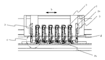
図1は、本発明のインクジェット記録装置のインクを吐出させて画像を記録する記録部の概略構成を模式的に示す構成図である。図2は、本発明の実施形態におけるインクジェット記録装置の主要部の概観斜視図である。図1、2において、ロール状に巻かれた被記録媒体4として記録紙6は、前記ロールからほどかれ図示しない駆動手段により回転制御される給紙ローラ8、9の挟持搬送(被記録媒体搬送手段)によって,記録紙6のガイドとなるガイド部材7a,7b、7c上に沿って矢印a方向に搬送される。また、ガイド部材7cから所定位置には画像形成された記録紙6を図示しない駆動手段により巻き取り制御可能な巻き取りローラ部5が構成され、画像形成後の記録紙6を巻き取ることが可能となっている。ガイド部材7b(プラテン)の搬送面に対向する部位にはガイド部材7bと所定間隔をおいて記録ヘッド1が搭載されたキャリッジ2が配置されている。前記記録ヘッド1には個々に所定インクが供給される構成となっている。(図示せず)
キャリッジ2は図示しない駆動手段によって駆動が伝達される構成となっており、駆動が伝達されるとキャリッジ2に固着された移動ガイド部12が装置の基本構造体である固定支柱部11に対し矢印b方向に往復移動(主走査)する。
FIG. 1 is a configuration diagram schematically showing a schematic configuration of a recording unit that records an image by ejecting ink in an ink jet recording apparatus of the present invention. FIG. 2 is a schematic perspective view of the main part of the ink jet recording apparatus according to the embodiment of the present invention. 1 and 2, the
The
また、主走査方向の非印字領域外(プラテン外)には記録ヘッド1の洗浄等を行なうサービスステーションが設けられており、このサービスステーションには、記録ヘッド1のノズル面1aを封止するキャッピング部、前記ノズル面1aを洗浄するワイプ部が配置されている。
Further, a service station for cleaning the
前記サービスステーションの各構成部材を駆動することにより記録ヘッド1での吐出準備が整うと外部ホストからの印字信号により、記録ヘッド1に伝達、印字信号に対応してインク液滴を記録紙6上に吐出し、イメージ画像の記録が行われる。
When the
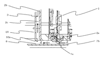
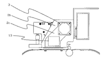
上記構成での画像形成過程において、記録ヘッド1での記録紙6記録面上に着滴したインクを強制的に乾燥させるため、金属材料で形成されるガイド部材7a,7b、7cの記録ヘッド1反対面には市販の面状ヒータ20,22線状ヒータ21等が設置され、金属の熱伝導特性を利用しガイド部材7a,7b、7c上を記録紙6が沿って搬送される際に記録紙6の裏面より加熱が行われる(乾燥手段)。従って、記録ヘッド1でのイメージ画像の記録過程において記録紙6の記録面にインク着滴した時点でインクの水分(主溶剤成分)の蒸発が発生し、蒸発物が記録面と対向配置された記録ヘッド1のノズル面1aに当たり結露、ノズル面1a上で液化することとなる。以下に、このノズル面1a上の液化を回避するための本発明について説明する。図3は、本発明の実施形態である図2のAA方向より断面とした要部断面図である。図4は、本発明の実施形態である図3のC部を詳細表示した要部拡大図である。図5は、本発明の実施形態である図2のB方向よりガイド板を除去した状態での概観斜視図である。
In the image forming process with the above configuration, the
図3、図4、図5においてキャリッジ2には、各記録ヘッド1が所定位置(XYZ方向)に仮設置可能な所定開口部を有し、前記記録ヘッド1が仮設置されたのち、キャリッジ2に搭載された固着可能な着脱機構(図示せず)によって固着される。前記固着された状態でのZ方向(鉛直方向)、ノズル面1aとガイド部材7bとの隙間は本実施形態では2.5mmと固定としたが、記録ヘッド1からのインク吐出能力が十分であればキャリッジ2と移動ガイド部12に隙間調整機構を設けることで可変設定することは可能である。
3, 4, and 5, the
キャリッジ2は、前記記録ヘッド1との接合が行われる底面部2aおよび移動ガイド部12との設置が図られる背面部2dからなるL字状の主構造体と、前記主構造体の主走査方向(矢印b)両側面に設けられた一対の側板構造体2bで骨格構成されている。そして、この主構造体と側板構造体2bに囲まれた部分に記録ヘッド1等が設置されている。本実施形態では、前記キャリッジ2をアルミ材での分離構成としたが、プラッスチック成型等での一体加工形成でもよく、構成を限定するものではない。
The
前記側板構造体2bの側面には、送風ファン3が固着設置される第一凹部2eが設けられている。そして側壁構造体2bには、第一凹部2eに連通し、キャリッジ2がガイド部材7bと対向する位置まで延設された凹ガイド部2cがさらに形成されている。この凹ガイド部2cは前記第一凹部2eよりさらに一段下がっており、送風ファン3の流出入空気を側板構造体2b内部で一定に整流されるように形成されている。また、送風ファン3からの空気の流れが、効率的にノズル面1aと被記録媒体との間に送られるように、凹ガイド部2cには蓋の役割をするガイド板10が圧入設置されている。このガイド板10はプラスチック材料で形成されている。このことにより、図2、図4、図5に示されるように、第一凹部2eおよび凹ガイド部2cは、一方が送風ファンにより閉鎖され、他方がノズル面1aとガイド部材7bとの隙間に向かって開口する矩形状の開口部が形成された閉鎖空間となっている。
A first recess 2e to which the
前記矩形状の開口部を主走査方向より見た幅寸法は、記録ヘッド1の吐出有効ノズル寸法よりも大きく、終始有効ノズル(記録ヘッド1上の両端に設けられたインク吐出を行なうノズル)から各々均等位置に配置されている。本実施形態では、ノズル面1a上の液化影響を回避するたに必要最小限の開口部の形状とするために、評価結果より終始有効ノズルより各5.0mm広げた開口部幅となっている。
The width of the rectangular opening as viewed from the main scanning direction is larger than the effective discharge nozzle size of the
一方、前記矩形状の開口部の副走査方向(矢印a方向)の断面形状は図3、図4に示すようにガイド板10の端部10a先端が鉛直方向でノズル面1aより記録紙6側に0.5mm下がった位置にある。そして、前記空気整流空間である凹ガイド部2cの断面積が、ガイド板10の端部10aに向かうにつれて縮小すると共に、ガイド板10の端部10a及び側板構造体2bの端部は、ノズル面1aとガイド部材7bとの隙間を流動する空気が記録紙6と極力平行流となるように導引されるべく隣接記録ヘッド1側に所定角度に曲げられた形状構成となっている。これは、前記ガイド板10の端部10a先端位置をノズル面1aより張り出すことで、キャリッジ2動作、イメージ画像記録時の記録紙6のシワ等によるジャム不具合によるノズル面1aへの破損防止のための機能をも兼ね備えている。また、前記所定形状・空気整流空間の断面積縮小率については、送付ファン3の空気送風量とキャリッジ2の動作速度と装置適用対象となる記録紙6の種類と装置環境等をパラメータとした評価より最適な構成とした。このように、被記録媒体のインク乾燥用(乾燥手段)とは別に、ノズル面1aとガイド部材7bとの隙間に空気の流れを発生させる手段を設けることにより、ノズル面1aへの結露を効果的に防止することが出来る。
On the other hand, the cross-sectional shape of the rectangular opening in the sub-scanning direction (arrow a direction) is as shown in FIGS. 3 and 4, and the tip of the
本実施形態では、前記ノズル面1aとガイド部材7bとの隙間への空気導入のために、キャリッジ2の構造体となる両側2つの側板構造体2bに送風ファン3を設け、一方は記録紙6に対し空気流入となるように吹付け駆動とし、他方は記録紙6に対し空気排出となるように吐き出し駆動となるように構成した。また、図5に示すように記録紙6に対し吹付け側となる凹ガイド部2c端部10aの近傍には温風吹付けが可能なように市販の温度制御機能付きのフィルムヒータ13が両面テープで所定位置に貼付され、フィルムヒータ13が所定温度に保持された状態になるように設定される。前記キャリッジ2の重量・スペース効率等の設計的制約を回避する案とした他の実施形態として、記録紙6面上での空気流動性は若干劣るが、両側2つの側板構造体2bの片側のみに送風ファン3を設け、記録紙6に対し空気流入・空気排出のどちらかを選択するかたちで送風ファン3を駆動する構成もある。本実施形態では、前記送風ファン3をスペース効率等の観点から市販の軸流型ファンを選定し、送風ファン3の機能である送風量を段階的に制御できるようにファンの回転速度を制御する入力パルス幅比率を変化させる制御可能(PWM制御)な駆動構成とした。
In the present embodiment, in order to introduce air into the gap between the nozzle surface 1a and the
上記のように構成されたキャリッジ2・記録ヘッド1において、キャリッジ2両側の送風ファン3及びフィルムヒータ13の駆動が開始される。図3での右側の吹付け側となる送風ファン3でのキャリッジ2周囲より流入した空気は、側板構造体2bの凹ガイド部2cを通り、フィルムヒータ13上で暖められた空気が所定温度の温風となってノズル面1aと被記録媒体との隙間に送りこまれる。(矢印d方向)
この隙間に送り込まれた温風は、他方の吐き出し側の送風ファン3による流線誘導効果も作用し図3、図4に示されるよう主走査方向(矢印b方向)の記録紙6に沿うかたちで流線が曲げられる。前記曲げられた空気(温風)の流線は、各記録ヘッド1のノズル面1aとガイド部材7bとの隙間を側板構造体2bの凹ガイド部2cの記録紙6側開口幅で、ほぼ一定流速分布を呈した強制的な空気(温風)の流れとして形成される。ここで送風ファン3駆動は一定速とし、この送風を考慮したインク吐出駆動を行なうことにより、印字品質を良好に保つことが出来る。今、記録ヘッド1からのインク吐出・イメージ画像の記録が開始され、ガイド部材7a,7bに設けられたヒータで暖められた記録紙6の記録面上にインク着滴するとインクの水分(主溶剤成分)の蒸発が開始され、記録紙6の記録面上から各ノズル面1aに向かって湯気となって立ちのぼりが開始される。しかしながら前記湯気は、前述のノズル面1aとガイド部材7bとの隙間に、被記録媒体の搬送方向と直行する記録ヘッド主走査方向(掃引方向)に沿って形成された空気(温風)の流れにより排除されることになる。記録紙6の記録面上から湯気が排除されることで、ノズル面1a上に湯気が付着し、結露によってノズル面1a上に液化成分が付着することを抑止することができる。
本実施形態では、前記強制的な空気の流れを温風としたが、フィルムヒータ13を駆動させない状態での空気の流れであってもノズル面1a上へ液化成分の付着抑止効果は期待できる。
また、本実施形態では、前述のノズル面1a上に液化成分の付着抑止する一連の動作をイメージ画像の記録時中は常時動作としたが、他の実施形態として、主にノズル面1a上に液化成分が付着する過程がノズル面1aと装置周囲温度との温度差での結露よる、記録ヘッド1・ノズル面1aの低温状態下での発生であることから、記録ヘッド1の吐出機能確保のために記録ヘッド1に既存搭載されている温度検出機能から記録ヘッド1温度を検出し、所定温度以下の状態においては前述の液化成分の付着抑止動作を駆動し、所定温度以上の状態においては付着抑止動作を停止することで、ノズル面1a上の液化成分の付着抑止ができ、且つ、消費電力の低減が図れる。
In the
The warm air sent into this gap also acts as a streamline induction effect by the
In the present embodiment, the forced air flow is warm air, but even if the air flow is in a state where the
In this embodiment, the series of operations for suppressing the adhesion of the liquefied component on the nozzle surface 1a is always performed during image recording. However, as another embodiment, the operation is mainly performed on the nozzle surface 1a. Since the process in which the liquefied component adheres is caused by condensation due to the temperature difference between the nozzle surface 1a and the ambient temperature of the apparatus, the discharge function of the
以上のことにより、記録ヘッド1が搭載されるキャリッジ2にノズル面1aとガイド部材7bとの隙間に強制的な空気の流れを形成する部材を構成することでイメージ画像記録時、記録紙6を強制的に乾燥処理した過程でのノズル面1a上の液化成分の付着抑止ができることでインク滴を安定して吐出することの出来る安定性の高いインクジェット記録装置を実現することが出来る。
As described above, a member that forms a forced air flow in the gap between the nozzle surface 1a and the
1 記録ヘッド
1a ノズル面(吐出口面)
2 キャリッジ
2b 側板構造体
3 送風ファン
4 被記録媒体
6 記録紙
7b ガイド部材
10 ガイド板
10a 端部
13 フィルムヒータ
20 面状ヒータ(乾燥手段)
21 線状ヒータ(乾燥手段)
22 面状ヒータ(乾燥手段)
1 Recording head 1a Nozzle surface (ejection port surface)
2
21 Linear heater (drying means)
22 Planar heater (drying means)
Claims (8)
前記被記録媒体を搬送する被記録媒体搬送手段と、
前記被記録媒体記録面上の前記インクを乾燥定着させる乾燥手段と、
前記被記録媒体の記録面と前記記録ヘッドの吐出口面との隙間に強制的な空気の流れを発生させる手段と、からなるインクジェット記録装置。 A recording head for recording on a recording medium by discharging ink from an ejection port;
A recording medium conveying means for conveying the recording medium;
Drying means for drying and fixing the ink on the recording medium recording surface;
An ink jet recording apparatus comprising: means for generating a forced air flow in a gap between a recording surface of the recording medium and an ejection port surface of the recording head.
Priority Applications (1)
| Application Number | Priority Date | Filing Date | Title |
|---|---|---|---|
| JP2006011097A JP2007190801A (en) | 2006-01-19 | 2006-01-19 | Inkjet recording apparatus |
Applications Claiming Priority (1)
| Application Number | Priority Date | Filing Date | Title |
|---|---|---|---|
| JP2006011097A JP2007190801A (en) | 2006-01-19 | 2006-01-19 | Inkjet recording apparatus |
Publications (1)
| Publication Number | Publication Date |
|---|---|
| JP2007190801A true JP2007190801A (en) | 2007-08-02 |
Family
ID=38446857
Family Applications (1)
| Application Number | Title | Priority Date | Filing Date |
|---|---|---|---|
| JP2006011097A Pending JP2007190801A (en) | 2006-01-19 | 2006-01-19 | Inkjet recording apparatus |
Country Status (1)
| Country | Link |
|---|---|
| JP (1) | JP2007190801A (en) |
Cited By (3)
| Publication number | Priority date | Publication date | Assignee | Title |
|---|---|---|---|---|
| JP2014172248A (en) * | 2013-03-07 | 2014-09-22 | Konica Minolta Inc | Inkjet recording method |
| JP2017094326A (en) * | 2016-11-29 | 2017-06-01 | エックスジェット エルティーディー. | Printing system having structure that allows self-purge, precipitation prevention, and gas removal |
| JP2023019282A (en) * | 2021-07-29 | 2023-02-09 | キヤノン株式会社 | recording device |
Citations (3)
| Publication number | Priority date | Publication date | Assignee | Title |
|---|---|---|---|---|
| JPH01202452A (en) * | 1988-02-09 | 1989-08-15 | Canon Inc | Ink jet recorder |
| JPH06270412A (en) * | 1993-03-24 | 1994-09-27 | Seiko Instr Inc | Ink jet recording apparatus |
| JP2001191507A (en) * | 2000-01-07 | 2001-07-17 | Hewlett Packard Co <Hp> | Method and apparatus for drying ink-jet printing area |
-
2006
- 2006-01-19 JP JP2006011097A patent/JP2007190801A/en active Pending
Patent Citations (3)
| Publication number | Priority date | Publication date | Assignee | Title |
|---|---|---|---|---|
| JPH01202452A (en) * | 1988-02-09 | 1989-08-15 | Canon Inc | Ink jet recorder |
| JPH06270412A (en) * | 1993-03-24 | 1994-09-27 | Seiko Instr Inc | Ink jet recording apparatus |
| JP2001191507A (en) * | 2000-01-07 | 2001-07-17 | Hewlett Packard Co <Hp> | Method and apparatus for drying ink-jet printing area |
Cited By (4)
| Publication number | Priority date | Publication date | Assignee | Title |
|---|---|---|---|---|
| JP2014172248A (en) * | 2013-03-07 | 2014-09-22 | Konica Minolta Inc | Inkjet recording method |
| JP2017094326A (en) * | 2016-11-29 | 2017-06-01 | エックスジェット エルティーディー. | Printing system having structure that allows self-purge, precipitation prevention, and gas removal |
| JP2023019282A (en) * | 2021-07-29 | 2023-02-09 | キヤノン株式会社 | recording device |
| JP7706972B2 (en) | 2021-07-29 | 2025-07-14 | キヤノン株式会社 | Recording device |
Similar Documents
| Publication | Publication Date | Title |
|---|---|---|
| US9073355B2 (en) | Recording apparatus with a blowing unit provided in a cover | |
| US8277015B2 (en) | Image forming device | |
| JP6631709B2 (en) | Droplet ejection device | |
| JP2021104633A (en) | Recording device | |
| WO2013121994A1 (en) | Inkjet printing method, and inkjet printing device | |
| JP2011194570A (en) | Drying device and recording device equipped with the drying device | |
| JPH03184852A (en) | Ink jet recording device | |
| US8820884B2 (en) | Recording device and recording device control method | |
| JP5720316B2 (en) | printer | |
| JP2016064583A (en) | Liquid ejection device | |
| JP2756341B2 (en) | Ink jet recording device | |
| JP6943254B2 (en) | Droplet ejection device | |
| JP2007190801A (en) | Inkjet recording apparatus | |
| JP7322542B2 (en) | printer | |
| JP5532734B2 (en) | Recording device | |
| JP2004330637A (en) | Recording device | |
| JP5720832B2 (en) | Recording device | |
| JP2013028009A (en) | Image recording apparatus | |
| US9962962B2 (en) | Printing apparatus | |
| JP5311753B2 (en) | Image forming apparatus | |
| JPH0516370A (en) | Image recorder | |
| JP2006218807A (en) | Recording device | |
| JP2001219548A (en) | Ink jet recording device | |
| JP2022047663A (en) | Recording device | |
| CN102673132B (en) | Printer |
Legal Events
| Date | Code | Title | Description |
|---|---|---|---|
| A621 | Written request for application examination |
Free format text: JAPANESE INTERMEDIATE CODE: A621 Effective date: 20080805 |
|
| RD01 | Notification of change of attorney |
Free format text: JAPANESE INTERMEDIATE CODE: A7421 Effective date: 20091105 |
|
| RD01 | Notification of change of attorney |
Free format text: JAPANESE INTERMEDIATE CODE: A7421 Effective date: 20091113 |
|
| RD01 | Notification of change of attorney |
Free format text: JAPANESE INTERMEDIATE CODE: A7421 Effective date: 20091118 |
|
| A977 | Report on retrieval |
Free format text: JAPANESE INTERMEDIATE CODE: A971007 Effective date: 20101027 |
|
| A131 | Notification of reasons for refusal |
Free format text: JAPANESE INTERMEDIATE CODE: A131 Effective date: 20101102 |
|
| A521 | Written amendment |
Free format text: JAPANESE INTERMEDIATE CODE: A523 Effective date: 20101221 |
|
| A02 | Decision of refusal |
Free format text: JAPANESE INTERMEDIATE CODE: A02 Effective date: 20110118 |