JP2007184635A - Execution method of surface cleaning parts - Google Patents
Execution method of surface cleaning parts Download PDFInfo
- Publication number
- JP2007184635A JP2007184635A JP2007069672A JP2007069672A JP2007184635A JP 2007184635 A JP2007184635 A JP 2007184635A JP 2007069672 A JP2007069672 A JP 2007069672A JP 2007069672 A JP2007069672 A JP 2007069672A JP 2007184635 A JP2007184635 A JP 2007184635A
- Authority
- JP
- Japan
- Prior art keywords
- surface cleaning
- inert gas
- cleaned
- purity inert
- gas
- Prior art date
- Legal status (The legal status is an assumption and is not a legal conclusion. Google has not performed a legal analysis and makes no representation as to the accuracy of the status listed.)
- Granted
Links
- 238000004140 cleaning Methods 0.000 title claims abstract description 326
- 238000000034 method Methods 0.000 title claims abstract description 132
- 239000012298 atmosphere Substances 0.000 claims abstract description 28
- 238000011144 upstream manufacturing Methods 0.000 claims abstract description 20
- 239000007789 gas Substances 0.000 claims description 195
- 239000011261 inert gas Substances 0.000 claims description 174
- 238000010438 heat treatment Methods 0.000 claims description 107
- 239000000463 material Substances 0.000 claims description 59
- 238000012545 processing Methods 0.000 claims description 55
- 238000001816 cooling Methods 0.000 claims description 46
- 239000001257 hydrogen Substances 0.000 claims description 33
- 229910052739 hydrogen Inorganic materials 0.000 claims description 33
- 229910052751 metal Inorganic materials 0.000 claims description 29
- 239000002184 metal Substances 0.000 claims description 29
- 238000010276 construction Methods 0.000 claims description 24
- 239000000126 substance Substances 0.000 claims description 24
- 239000005416 organic matter Substances 0.000 claims description 22
- UFHFLCQGNIYNRP-UHFFFAOYSA-N Hydrogen Chemical compound [H][H] UFHFLCQGNIYNRP-UHFFFAOYSA-N 0.000 claims description 18
- 150000002431 hydrogen Chemical class 0.000 claims description 13
- 230000002093 peripheral effect Effects 0.000 claims description 12
- 239000007769 metal material Substances 0.000 claims description 11
- 238000007747 plating Methods 0.000 claims description 7
- 238000007789 sealing Methods 0.000 claims description 7
- -1 moisture Substances 0.000 claims description 5
- 238000001179 sorption measurement Methods 0.000 claims description 5
- 238000001465 metallisation Methods 0.000 claims 2
- 239000004065 semiconductor Substances 0.000 abstract description 65
- 238000004519 manufacturing process Methods 0.000 abstract description 42
- 238000011065 in-situ storage Methods 0.000 abstract 1
- 239000012535 impurity Substances 0.000 description 65
- 239000004014 plasticizer Substances 0.000 description 41
- 239000011347 resin Substances 0.000 description 38
- 229920005989 resin Polymers 0.000 description 38
- 239000000047 product Substances 0.000 description 33
- XKRFYHLGVUSROY-UHFFFAOYSA-N Argon Chemical compound [Ar] XKRFYHLGVUSROY-UHFFFAOYSA-N 0.000 description 27
- 238000005070 sampling Methods 0.000 description 24
- 238000003795 desorption Methods 0.000 description 17
- 238000011282 treatment Methods 0.000 description 17
- 235000012431 wafers Nutrition 0.000 description 16
- 229910052786 argon Inorganic materials 0.000 description 14
- 238000003860 storage Methods 0.000 description 14
- 238000012856 packing Methods 0.000 description 13
- 229910001220 stainless steel Inorganic materials 0.000 description 11
- 239000010935 stainless steel Substances 0.000 description 11
- PXHVJJICTQNCMI-UHFFFAOYSA-N Nickel Chemical compound [Ni] PXHVJJICTQNCMI-UHFFFAOYSA-N 0.000 description 10
- 238000005516 engineering process Methods 0.000 description 10
- 230000035945 sensitivity Effects 0.000 description 9
- 239000000758 substrate Substances 0.000 description 9
- 239000011810 insulating material Substances 0.000 description 6
- 238000004949 mass spectrometry Methods 0.000 description 6
- 238000010926 purge Methods 0.000 description 6
- 239000003795 chemical substances by application Substances 0.000 description 5
- 238000010586 diagram Methods 0.000 description 5
- 229910052759 nickel Inorganic materials 0.000 description 5
- 238000007740 vapor deposition Methods 0.000 description 5
- XLYOFNOQVPJJNP-UHFFFAOYSA-N water Substances O XLYOFNOQVPJJNP-UHFFFAOYSA-N 0.000 description 5
- WGLPBDUCMAPZCE-UHFFFAOYSA-N Trioxochromium Chemical compound O=[Cr](=O)=O WGLPBDUCMAPZCE-UHFFFAOYSA-N 0.000 description 4
- 229910000423 chromium oxide Inorganic materials 0.000 description 4
- 238000007599 discharging Methods 0.000 description 4
- 239000004973 liquid crystal related substance Substances 0.000 description 4
- 238000012544 monitoring process Methods 0.000 description 4
- 230000003287 optical effect Effects 0.000 description 4
- MQIUGAXCHLFZKX-UHFFFAOYSA-N Di-n-octyl phthalate Natural products CCCCCCCCOC(=O)C1=CC=CC=C1C(=O)OCCCCCCCC MQIUGAXCHLFZKX-UHFFFAOYSA-N 0.000 description 3
- BJQHLKABXJIVAM-UHFFFAOYSA-N bis(2-ethylhexyl) phthalate Chemical compound CCCCC(CC)COC(=O)C1=CC=CC=C1C(=O)OCC(CC)CCCC BJQHLKABXJIVAM-UHFFFAOYSA-N 0.000 description 3
- 239000011651 chromium Substances 0.000 description 3
- 238000009833 condensation Methods 0.000 description 3
- 230000005494 condensation Effects 0.000 description 3
- 230000000694 effects Effects 0.000 description 3
- 238000002161 passivation Methods 0.000 description 3
- 238000004381 surface treatment Methods 0.000 description 3
- NBIIXXVUZAFLBC-UHFFFAOYSA-N Phosphoric acid Chemical compound OP(O)(O)=O NBIIXXVUZAFLBC-UHFFFAOYSA-N 0.000 description 2
- QAOWNCQODCNURD-UHFFFAOYSA-N Sulfuric acid Chemical compound OS(O)(=O)=O QAOWNCQODCNURD-UHFFFAOYSA-N 0.000 description 2
- 238000004458 analytical method Methods 0.000 description 2
- 238000005452 bending Methods 0.000 description 2
- 238000006243 chemical reaction Methods 0.000 description 2
- 239000007788 liquid Substances 0.000 description 2
- 238000005498 polishing Methods 0.000 description 2
- 238000005406 washing Methods 0.000 description 2
- 238000003466 welding Methods 0.000 description 2
- IJGRMHOSHXDMSA-UHFFFAOYSA-N Atomic nitrogen Chemical compound N#N IJGRMHOSHXDMSA-UHFFFAOYSA-N 0.000 description 1
- 239000004215 Carbon black (E152) Substances 0.000 description 1
- 229910000831 Steel Inorganic materials 0.000 description 1
- BZHJMEDXRYGGRV-UHFFFAOYSA-N Vinyl chloride Chemical compound ClC=C BZHJMEDXRYGGRV-UHFFFAOYSA-N 0.000 description 1
- 229910052782 aluminium Inorganic materials 0.000 description 1
- XAGFODPZIPBFFR-UHFFFAOYSA-N aluminium Chemical compound [Al] XAGFODPZIPBFFR-UHFFFAOYSA-N 0.000 description 1
- 229910000147 aluminium phosphate Inorganic materials 0.000 description 1
- 238000013459 approach Methods 0.000 description 1
- 230000015572 biosynthetic process Effects 0.000 description 1
- 238000011109 contamination Methods 0.000 description 1
- 229910001873 dinitrogen Inorganic materials 0.000 description 1
- OEIWPNWSDYFMIL-UHFFFAOYSA-N dioctyl benzene-1,4-dicarboxylate Chemical compound CCCCCCCCOC(=O)C1=CC=C(C(=O)OCCCCCCCC)C=C1 OEIWPNWSDYFMIL-UHFFFAOYSA-N 0.000 description 1
- 238000005530 etching Methods 0.000 description 1
- 238000004868 gas analysis Methods 0.000 description 1
- 239000001307 helium Substances 0.000 description 1
- 229910052734 helium Inorganic materials 0.000 description 1
- SWQJXJOGLNCZEY-UHFFFAOYSA-N helium atom Chemical compound [He] SWQJXJOGLNCZEY-UHFFFAOYSA-N 0.000 description 1
- 229930195733 hydrocarbon Natural products 0.000 description 1
- 150000002430 hydrocarbons Chemical class 0.000 description 1
- 238000007689 inspection Methods 0.000 description 1
- 150000002500 ions Chemical class 0.000 description 1
- 150000002605 large molecules Chemical class 0.000 description 1
- 239000002932 luster Substances 0.000 description 1
- 229920002521 macromolecule Polymers 0.000 description 1
- 238000012423 maintenance Methods 0.000 description 1
- 230000001590 oxidative effect Effects 0.000 description 1
- 238000004806 packaging method and process Methods 0.000 description 1
- 229920003023 plastic Polymers 0.000 description 1
- 239000004033 plastic Substances 0.000 description 1
- 238000003672 processing method Methods 0.000 description 1
- 239000012264 purified product Substances 0.000 description 1
- 230000005855 radiation Effects 0.000 description 1
- 238000011160 research Methods 0.000 description 1
- 230000000630 rising effect Effects 0.000 description 1
- 238000010206 sensitivity analysis Methods 0.000 description 1
- 238000000926 separation method Methods 0.000 description 1
- 238000004904 shortening Methods 0.000 description 1
- 239000002904 solvent Substances 0.000 description 1
- 239000010959 steel Substances 0.000 description 1
- 238000009489 vacuum treatment Methods 0.000 description 1
Images


Landscapes
- Cleaning In General (AREA)
- Cleaning And De-Greasing Of Metallic Materials By Chemical Methods (AREA)
- Cleaning Or Drying Semiconductors (AREA)
Abstract
Description
本発明は、例えば半導体製造工場等に用いられる高純度ガス供給システムに適用して有効な技術に関するものである。 The present invention relates to a technique effective when applied to a high-purity gas supply system used in, for example, a semiconductor manufacturing factory.
本発明は、表面清浄化部品の施工方法に関するものである。 The present invention relates to a method for constructing a surface cleaning component.
近年、半導体製造工程に用いられる高純度ガス供給システムにおいては、電界研磨処理、真空中での昇温脱離処理、クロム酸化膜不働態処理(Cr2O3膜)等を行ったガス供給部品が使用されている。また、従来の高純度ガス供給システムの施工方法においては、現地で電解研磨処理をした部品を用いて、曲げ加工を行ったり、溶接を行ったりして組み立てを行っていた。 In recent years, in high-purity gas supply systems used in semiconductor manufacturing processes, gas supply components that have been subjected to electropolishing, temperature programmed desorption in vacuum, chromium oxide film passivation (Cr 2 O 3 film), etc. Is used. In addition, in the conventional high purity gas supply system construction method, assembly is performed by bending or welding using parts that have been subjected to electrolytic polishing treatment in the field.
電界研磨処理は、硫酸とリン酸をベースとした電界研磨液を用いて、処理部品を陽極、相対電極を陰極とし、処理部品と電極の間に直流電流を流しながら、研磨を行って行く処理方法で、このあと溶剤洗浄、純水洗浄を行って乾燥させる処理である。また、真空中での昇温脱離処理は、真空ポンプで処理室内を真空に引きながら加熱を行い、処理部品に付着している脱離成分を除去する処理方法である。また、クロム酸化膜不働態処理(Cr2O3膜)は、酸化ガス雰囲気で、高温に加熱し、ステンレス表面にCr2O3膜を形成させる処理方法である。 The electropolishing process uses an electropolishing solution based on sulfuric acid and phosphoric acid, with the processing component as the anode and the relative electrode as the cathode, and polishing with direct current flowing between the processing component and the electrode. In this method, the solvent is then washed with pure water and dried. Further, the temperature-programmed desorption process in vacuum is a processing method in which heating is performed while a processing chamber is evacuated with a vacuum pump to remove desorbed components adhering to the processing components. The chromium oxide film passivation treatment (Cr 2 O 3 film) is a treatment method in which a Cr 2 O 3 film is formed on the stainless steel surface by heating to a high temperature in an oxidizing gas atmosphere.
また、下記特許文献1には、減圧下にて成膜又はエッチングを行う装置の非動作時には、該装置に超高純度ガスを送入するための配管をすくなくともある一定期間加熱するとともに、該配管から超高純度ガスを配管外に排出し、前記装置の動作時には該配管の加熱を停止して超高純度ガスを該装置の導入口を介して該配管から該装置内に送入することを特徴とする超高純度ガスの供給方法が、開示されている。
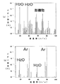
しかしながら、電界研磨処理においては、電界研磨液や洗浄液が残留しており、真空中での昇温脱離処理では、昇温加熱時に脱離成分を除去しても、冷却時、及び、真空雰囲気から大気雰囲気に戻す際に真空ポンプからのオイルバックにより、オイル成分が再付着するという問題点があり、クロム酸化膜不働態処理では、金属表面に膜を形成させるため、長時間の使用時に膜が剥離するという問題点があった。また、すべての処理に関して、処理後大気に暴露するため、大気中の有機物が付着するという問題点と、さらに、処理後の梱包方法においても、塩化ビニール等の樹脂フィルムにより封じられるため、樹脂中に含まれる軟化剤、可塑剤と呼ばれるディオクチルフタレイト(DOP)等の有機物が脱離し、再付着するという問題点があることがわかった。これらは、今まで有機物の高感度分析手法が、確立されておらず、検査が難しかったため、問題とされていなかったが、高純度アルゴンガスを用いた大気圧イオン化質量分析(APIMS)、高圧イオン化質量分析(HPIMS)といった高感度な分析手法により、確認できるようになった。 However, in the electropolishing process, the electropolishing liquid and the cleaning liquid remain, and in the temperature programmed desorption process in vacuum, even if the desorbed component is removed during the temperature rising heating, the cooling process and the vacuum atmosphere are performed. When returning to the atmosphere from the atmosphere, there is a problem that the oil component is reattached by the oil back from the vacuum pump. In the chromium oxide film passivation treatment, a film is formed on the metal surface. There was a problem of peeling. In addition, since all the treatments are exposed to the atmosphere after treatment, organic matter in the atmosphere adheres to them, and furthermore, the packaging method after treatment is sealed with a resin film such as vinyl chloride, It has been found that there is a problem that organic substances such as dioctyl phthalate (DOP) called softener and plasticizer contained in the material are detached and reattached. These were not considered to be a problem because a high-sensitivity analysis method for organic substances has not been established so far, and inspection was difficult, but atmospheric pressure ionization mass spectrometry (APIMS) using high-purity argon gas, high-pressure ionization This can be confirmed by a highly sensitive analytical technique such as mass spectrometry (HPIMS).
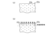
さらに、本発明者は、ステンレス鋼材料、ニッケル材料、ニッケル蒸着材料、乃至ニッケルメッキ材料表面には、水素が高濃度で吸着しており、これが大気中の水分、有機物と結合を起こしやすく、一度結合すると脱離しにくいこと、有機物の種類によっては、水素と有機物の結合部を核として、有機物の凝縮が進行し、突起物が成長することを見いだした。また、表面の水素濃度を低減していれば、水分、有機物がステンレス鋼表面と結合しにくいだけでなく、脱離も容易であること、さらに、ステンレス鋼においては水素の脱離ピークが350℃にあり、水素の脱離とともに水分やほとんどの有機物が脱離し、350℃以上の温度が脱離効率が優れていることを見出した。 Furthermore, the present inventor has adsorbed hydrogen at a high concentration on the surface of stainless steel material, nickel material, nickel vapor deposition material, or nickel plating material, which tends to cause bonding with moisture and organic matter in the atmosphere. It was found that when bonded, it was difficult to desorb, and depending on the type of organic substance, condensation of the organic substance progressed with the bond between hydrogen and organic substance as the nucleus, and protrusions grew. Moreover, if the hydrogen concentration on the surface is reduced, not only moisture and organic substances are not easily bonded to the stainless steel surface, but also desorption is easy. Further, in stainless steel, the hydrogen desorption peak is 350 ° C. It was found that moisture and most organic substances were desorbed along with the desorption of hydrogen, and the desorption efficiency was excellent at a temperature of 350 ° C. or higher.
また、例えばパッキン等の配管部品として、可塑剤を有する樹脂材料から成る樹脂部品を高純度ガス供給システムに使用した場合、その表面側領域にて樹脂中に含まれる例えばディオクチルテレフタレイト(DOP)等の可塑剤が脱離して、高純度ガス中に混入してしまうため、高純度ガスの純度が低下してしまうと共に、脱離した可塑剤が高純度ガス供給システムの他の箇所で再付着することになるという問題があった。 Further, when a resin component made of a resin material having a plasticizer is used as a piping component such as a packing in a high-purity gas supply system, for example, dioctyl terephthalate (DOP) contained in the resin in the surface side region. ) And the like are desorbed and mixed into the high-purity gas, so that the purity of the high-purity gas is reduced and the desorbed plasticizer is recycled at other locations in the high-purity gas supply system. There was a problem of sticking.
さらに、例えば半導体ウェハの保管容器や半導体部品の保持容器が可塑剤を有する樹脂材料から構成されている場合、これらの容器は、従来純水による洗浄のみにより清浄化されているため、使用の際に、樹脂材料から可塑剤が脱離して、半導体ウェハや半導体部品に付着してしまう等の問題があった。 Further, for example, when a semiconductor wafer storage container or a semiconductor component holding container is made of a resin material having a plasticizer, these containers are conventionally cleaned only by washing with pure water. In addition, there is a problem that the plasticizer is detached from the resin material and adheres to the semiconductor wafer or the semiconductor component.
本発明は、このような従来の技術が有する問題点に鑑みなされたもので、その目的とするところは、高純度ガス供給部品(配管)からの水素、水分、有機物の除去技術及び再付着防止技術を提供し、この技術により表面清浄化部品を提供すること、また、磁気ディスク基板、光ディスク基板、半導体ウェハ、液晶、金属パッキン等の表面に有機物起因の突起物の成長を防止できる技術を提供すること、さらに、半導体製造装置等における高純度ガス供給システムの現地での施工時間や施工後のシステム立ち上げ時間(使用可能となるまでの時間)やメンテナンス時間を短縮できる技術を提供することにある。 The present invention has been made in view of such problems of the conventional technology, and the object of the present invention is to remove hydrogen, moisture and organic substances from high-purity gas supply parts (piping) and prevent re-adhesion. Providing technology, providing surface cleaning parts by this technology, and providing technology that can prevent the growth of protrusions due to organic matter on the surface of magnetic disk substrates, optical disk substrates, semiconductor wafers, liquid crystals, metal packing, etc. In addition, to provide technology that can reduce the on-site construction time of the high-purity gas supply system in semiconductor manufacturing equipment, the system startup time after construction (time until it can be used), and maintenance time is there.
さらに、本発明は、可塑剤の脱離を低減するようにした、半導体ウェハの保管容器や半導体装置の保持容器等あるいはパッキン等の配管部品等の、可塑剤を有する樹脂材料を少なくとも一部に有するから成る物品を提供することを目的とする。 Furthermore, the present invention provides at least a part of a resin material having a plasticizer, such as a semiconductor wafer storage container, a semiconductor device holding container, or piping parts such as packing, which reduces the detachment of the plasticizer. The object is to provide an article comprising.
ここでは、前記課題を解決する技術手段として、下記第1乃至第52の態様を提示する。なお、下記第11の態様が請求項1乃至3に係る発明に相当し、下記第12の態様が請求項4乃至6に係る発明に相当し、下記第47の態様が請求項7乃至12に係る発明に相当している。
Here, the following 1st thru | or 52nd aspect is shown as a technical means to solve the said subject. The following eleventh aspect corresponds to the invention according to
第1の態様による表面清浄化方法は、ガス流路内に高純度不活性ガスを通流させた状態で、被表面清浄化部品の外周部より昇温加熱を行った後、室温まで冷却して、実質的に酸化膜を形成させる事なく、ガス流路内に吸着している水素、水分、有機物の吸着量を低減させるものである。この第1の態様による表面清浄化方法によれば、ガスの流路内は高純度不活性ガスが通流しているので、脱離成分はこのガスで希釈され速やかに排出されていくので、酸化膜を形成することなく表面の清浄化が行われる。しかし、高温の状態で高純度不活性ガスの通流を止めてしまうと、脱離した不純物や、滞留している不純物が冷却の過程で再付着し、せっかく清浄化した表面が汚染してしまう。このため、高純度不活性ガスを通流させた状態で略々室温まで冷却することが好ましい。 In the surface cleaning method according to the first aspect, the high-purity inert gas is allowed to flow through the gas flow path, the temperature is raised from the outer periphery of the surface-cleaned component, and then cooled to room temperature. Thus, the amount of adsorption of hydrogen, moisture, and organic matter adsorbed in the gas flow path is reduced without substantially forming an oxide film. According to the surface cleaning method according to the first aspect, since the high purity inert gas flows in the gas flow path, the desorbed component is diluted with this gas and quickly discharged. The surface is cleaned without forming a film. However, if the flow of high-purity inert gas is stopped at a high temperature, the desorbed impurities and the remaining impurities are reattached during the cooling process, and the cleaned surface is contaminated. . For this reason, it is preferable to cool to about room temperature in a state where a high purity inert gas is allowed to flow.
第2の態様による表面清浄化方法は、前記第1の態様による表面清浄化方法において、たとえば、大気圧イオン化質量分析(APIMS)、高圧イオン化質量分析(HPIMS)といった水素、水分、有機物を高感度に検出する手段を備えるものである。この第2の態様による表面清浄化方法によれば、被表面清浄化部品から脱離した成分をモニタリングしながら表面清浄化が行えるため、表面清浄化の終点検出が可能となり、最適時間で処理を行うことが出来る。 The surface cleaning method according to the second aspect is the same as the surface cleaning method according to the first aspect except that, for example, atmospheric pressure ionization mass spectrometry (APIMS) and high pressure ionization mass spectrometry (HPIMS) are highly sensitive to hydrogen, moisture, and organic matter. It is provided with the means to detect. According to the surface cleaning method according to the second aspect, the surface cleaning can be performed while monitoring the components detached from the surface cleaning component. Therefore, the end point of the surface cleaning can be detected, and the processing can be performed in the optimum time. Can be done.
第3の態様による表面清浄化方法は、前記第1又は第2の態様による表面清浄化方法において、高純度不活性ガスとして、高純度アルゴンガスを用いるものである。この第3の態様による表面清浄化方法によれば、高純度不活性ガスのうちで表面に吸着している不純物の除去能力が最も優れているアルゴンガスを用いている。本発明者の研究では、アルゴンガスはヘリウムガスの約8倍、窒素ガスの約2倍の除去能力があることがわかった。これは、分子量にほぼ比例しており、分子の大きな不活性ガスが除去効果が高いことを示している。また、アルゴンガスは水素の分析をAPIMSやHPIMSを用いて行う場合、Ar・H(M/z=41)でモニタリングするが、高純度アルゴンではM/z=41のバックグランドの値は極めて低いので、低濃度から水素をモニタリング出来る。 The surface cleaning method according to the third aspect uses high purity argon gas as the high purity inert gas in the surface cleaning method according to the first or second aspect. According to the surface cleaning method according to the third aspect, argon gas having the best ability to remove impurities adsorbed on the surface among the high purity inert gases is used. In the research conducted by the present inventor, it has been found that argon gas is capable of removing about 8 times helium gas and about 2 times nitrogen gas. This is almost proportional to the molecular weight, and shows that an inert gas having a large molecule has a high removal effect. Argon gas is monitored by Ar · H (M / z = 41) when hydrogen is analyzed using APIMS or HPIMS, but the background value of M / z = 41 is extremely low in high-purity argon. Therefore, hydrogen can be monitored from a low concentration.
第4の態様による表面清浄化方法は、前記第1乃至第3のいずれかの態様による表面清浄化方法において、350℃以上の温度で昇温加熱を行うものである。この第4の態様による表面清浄化方法によれば、ステンレス鋼においては水素の脱離ピークが350℃にあり、水素の脱離とともに水分やほとんどの有機物が脱離し、350℃以上の温度が脱離効率が優れているためである。 A surface cleaning method according to a fourth aspect is the surface cleaning method according to any one of the first to third aspects, in which heating is performed at a temperature of 350 ° C. or higher. According to the surface cleaning method of the fourth aspect, hydrogen has a desorption peak at 350 ° C. in stainless steel, and moisture and most organic substances are desorbed along with the desorption of hydrogen. This is because the separation efficiency is excellent.
第5の態様による表面清浄化方法は、高純度不活性ガスを通流させた雰囲気で、金属材料、金属蒸着材料、乃至金属メッキ材料のいずれかを、少なくとも一部に有する被表面清浄化部品を昇温加熱した後、室温まで冷却して、実質的に酸化膜を形成させることなく、表面の水素濃度を低減させるものである。この第5の態様による表面清浄化方法によれば、金属材料表面の水素を完全に脱離させることにより、表面清浄化処理後の表面に水素結合を介して水分、有機物が再付着しにくくなり、付着した水分、有機物を核として有機物の凝縮が進行し、デンドライト状の突起物が成長するのを防止できる。金属材料の中でも、ニツケル、ステンレスのように水素を表面に貯蔵しやすい材料に最も効果があり、被表面清浄化部品としては、磁気ディスク基板、光ディスク基板、半導体ウェハ、液晶、金属パッキンが最も効果がある。 The surface cleaning method according to the fifth aspect includes a surface cleaning component having at least a part of any one of a metal material, a metal vapor deposition material, and a metal plating material in an atmosphere in which a high purity inert gas is passed. After the temperature is raised and heated, it is cooled to room temperature, and the hydrogen concentration on the surface is reduced without substantially forming an oxide film. According to the surface cleaning method according to the fifth aspect, by completely desorbing hydrogen on the surface of the metal material, it becomes difficult for moisture and organic substances to be reattached to the surface after the surface cleaning process through hydrogen bonds. It is possible to prevent the dendrite-like protrusions from growing due to the condensation of the organic matter with the attached moisture and organic matter as the core. Among metal materials, it is most effective for materials that easily store hydrogen on the surface, such as nickel and stainless steel, and magnetic disk substrate, optical disk substrate, semiconductor wafer, liquid crystal, and metal packing are the most effective as the parts to be cleaned. There is.
第6の態様による表面清浄化装置は、ガスの流れ方向に沿って、高純度不活性ガス流入口、被表面清浄化部品、ガスサンプリング配管、高感度ガス分析装置の順序で構成され、被表面清浄化部品の外周部に加熱手段を備えるものである。この第6の態様による表面清浄化装置によれば、高純度不活性ガスを被表面清浄化部品に通流させながら被表面清浄化部品の外周部に備えられた加熱手段により、被表面清浄化部品を加熱することにより、表面に吸着している水素、水分、有機物を脱離させ、これをガスサンプリング配管を通して高感度ガス分析装置まで導いている。この場合、このガスサンプリング配管は、室温では水分、有機物が吸着してしまうため、高温に加熱することが好ましい。 The surface cleaning apparatus according to the sixth aspect includes a high purity inert gas inlet, a surface cleaning component, a gas sampling pipe, and a high sensitivity gas analyzer along the gas flow direction. A heating means is provided on the outer peripheral portion of the cleaning component. According to the surface cleaning apparatus of the sixth aspect, the surface cleaning is performed by the heating means provided on the outer peripheral portion of the surface cleaning component while passing the high purity inert gas through the surface cleaning component. By heating the parts, hydrogen, moisture, and organic substances adsorbed on the surface are desorbed, and this is led to a highly sensitive gas analyzer through a gas sampling pipe. In this case, the gas sampling pipe is preferably heated to a high temperature because moisture and organic substances are adsorbed at room temperature.
第7の態様による表面清浄化装置は、前記第6の態様による表面清浄化装置において、ガスサンプリング配管にガス切り替え手段を備えるものである。この第7の態様による表面清浄化装置によれば、ガスサンプリング配管に備えたガス切り替え手段により、複数の被表面清浄化部品を1台の高感度ガス分析装置で分析することが可能となり分析のコストを低減することが出来る。また、ガスの切り替えに際し、ガスサンプリングをしていない間も被表面清浄化部品にはガスを通流しておく必要があり、ガス切り替え手段の一方の出口は大気開放か、排気ダクト等に接続されていることが望ましい。 A surface cleaning apparatus according to a seventh aspect is the surface cleaning apparatus according to the sixth aspect, wherein the gas sampling pipe is provided with a gas switching means. According to the surface cleaning apparatus of the seventh aspect, the gas switching means provided in the gas sampling pipe enables a plurality of surface cleaning parts to be analyzed with one high-sensitivity gas analyzer. Cost can be reduced. In addition, when gas is switched, it is necessary to allow gas to flow through the surface-cleaned parts even during gas sampling, and one outlet of the gas switching means is open to the atmosphere or connected to an exhaust duct or the like. It is desirable that
第8の態様による表面清浄化装置は、前記第6又は第7の態様による表面清浄化装置において、全長の長い被表面清浄化部品において、加熱領域を複数に分轄して、加熱領域をガスの流れ方向に沿って上流側から下流側へ移動させて行く表面清浄化装置である。この第8の態様による表面清浄化装置によれば、被表面清浄化部品の全長が長いため、全てをいっきに加熱した場合、下流部で不純物濃度が高濃度となり、酸化膜が形成される恐れがある場合、いくつかに分割して加熱処理を行うものである。この際、加熱の順序は脱離成分の再付着を防止するためガスの流れ方向に沿って上流側から下流側へと移動する。 The surface cleaning apparatus according to an eighth aspect is the surface cleaning apparatus according to the sixth or seventh aspect, wherein the heating region is divided into a plurality of parts in the surface cleaning component having a long overall length, and the heating region is made of gas. It is a surface cleaning device that moves from the upstream side to the downstream side along the flow direction. According to the surface cleaning apparatus of the eighth aspect, since the entire length of the surface cleaning component is long, when all are heated at the same time, there is a possibility that the impurity concentration becomes high in the downstream portion and an oxide film is formed. In some cases, the heat treatment is carried out in several parts. At this time, the heating sequence moves from the upstream side to the downstream side along the gas flow direction in order to prevent reattachment of the desorbed components.
第9の態様による表面清浄化部品は、前記第1乃至第5のいずれかの態様による表面清浄化処理を行った後、大気に暴露させる事なく高純度不活性ガスを充満させて気密封じを行った表面清浄化部品である。この第9の態様による表面清浄化部品によれば、表面清浄化処理後の気密封じにより、大気や、梱包材等に含まれる水分、有機物の再付着を防止することが出来る。 The surface cleaning component according to the ninth aspect is subjected to the surface cleaning process according to any one of the first to fifth aspects, and then is filled with a high-purity inert gas without being exposed to the atmosphere to be hermetically sealed. This is the surface cleaning component that was performed. According to the surface cleaning component according to the ninth aspect, re-adhesion of moisture, organic substances contained in the atmosphere, packing materials, and the like can be prevented by air-sealing after the surface cleaning treatment.
第10の態様による表面清浄化部品は、前記第9の態様による表面清浄化部品において、当該表面清浄化部品の一部に高純度不活性ガス保有容器を備えるものである。この第10の態様による表面清浄化部品によれば、表面清浄化部品の接続(現地組み立て作業)に際し、高純度不活性ガスの保有容器に貯えられた高圧の高純度不活性ガスを放出(パージ)させながら接続を続けていくことが可能で、表面清浄化部品の内部への大気の流入を防止できる。この際、高純度不活性ガス保有容器は、終端に取り付けておくことが望ましく、被表面清浄化部品を接続したら、高純度不活性ガス保有容器は取り外して、工場側の高純度不活性ガスを放出(パージ)させながら接続を続けていくことが好ましい。 The surface cleaning component according to the tenth aspect is the surface cleaning component according to the ninth aspect, wherein a part of the surface cleaning component includes a high-purity inert gas holding container. According to the surface cleaning component according to the tenth aspect, when connecting the surface cleaning component (on-site assembly operation), the high-purity inert gas stored in the high-purity inert gas holding container is released (purged). ) And the connection can be continued, and the inflow of air into the surface cleaning component can be prevented. At this time, it is desirable to attach the high purity inert gas holding container to the end, and after connecting the surface cleaning parts, remove the high purity inert gas holding container and supply the factory side high purity inert gas. It is preferable to continue the connection while discharging (purging).
第11の態様による表面清浄化部品の施工方法は、前記第9又は第10の態様による複数個の表面清浄化部品を組み立てるに際し、高純度不活性ガスを流しながら、ガスの流れ方向に沿って上流側から下流側へと組み立てを行っていくものである。この第11の態様による施工方法によれば、高純度不活性ガスを放出(パージ)させながら接続を続けていくため、表面清浄化部品内部に大気の流入がなく、水分、有機物の再吸着を防止できる。 In the construction method of the surface cleaning component according to the eleventh aspect, when assembling the plurality of surface cleaning components according to the ninth or tenth aspect, along the gas flow direction while flowing a high purity inert gas. Assembly is performed from the upstream side to the downstream side. According to the construction method of the eleventh aspect, since the connection is continued while discharging (purging) high purity inert gas, there is no inflow of air into the surface cleaning component, and moisture and organic matter are re-adsorbed. Can be prevented.
第12の態様による表面清浄化部品の施工方法は、表面清浄化処理工場にて、第9又は第10の態様による表面清浄化部品を製作し、輸送手段を用いて現地まで輸送し、現地にて組み立てを行うものである。この第12の態様による施工方法によれば、現地での曲げ加工、溶接等の時間のかかる作業が必要なく短時間での施工が可能となる。たとえば、従来の施工方法との施工時間の比較を行えば、本発明を用いた施工方法では、従来の約1/5で施工を行うことが出来る。また、部品の共通化が可能となり、高純度ガス供給システムの価格低減も可能となる。 In the surface cleaning component construction method according to the twelfth aspect, the surface cleaning component according to the ninth or tenth aspect is manufactured at the surface cleaning processing factory, and transported to the site using the transportation means. To assemble. According to the construction method of the twelfth aspect, time-consuming work such as on-site bending and welding is not required, and construction in a short time is possible. For example, if the construction time is compared with the conventional construction method, the construction method using the present invention can be constructed at about 1/5 of the conventional construction method. In addition, parts can be shared, and the price of the high-purity gas supply system can be reduced.
第13の態様による被表面清浄化物の表面清浄化方法は、ガス流路内に被表面清浄化物の被清浄化表面が露出し、前記被表面清浄化物の前記被清浄化表面が高い温度に保持された状態で、前記ガス流路内に高純度不活性ガスを通流させる第1の段階を備えたものである。なお、前記被表面清浄化物は、部品であっても、複数の部品が組み立てられたものであってもよい。また、前記被表面清浄化物の材質は何ら限定されるものではないが、後述する第16及び第17の態様にはその例を挙げている。 According to a thirteenth aspect of the surface cleaning method for a surface to be cleaned, the surface to be cleaned of the surface to be cleaned is exposed in the gas flow path, and the surface to be cleaned of the surface to be cleaned is kept at a high temperature. In this state, a first stage of flowing a high purity inert gas into the gas flow path is provided. The surface-cleaned product may be a component or a plurality of components assembled. The material of the surface-cleaned material is not limited at all, but examples thereof are given in the 16th and 17th aspects described later.
この第13の態様による表面清浄化方法によれば、ガス流路内に被表面清浄化物の表面が露出し、被表面清浄化物の表面が高い温度に保持された状態で、ガス流路内に高純度不活性ガスが通流しているので、被表面清浄化物の表面からの不純物等の脱離成分はこのガスで希釈され速やかに排出されていくので、被表面清浄化物の表面の清浄化が行なわれる。 According to the surface cleaning method of the thirteenth aspect, the surface of the surface cleaning object is exposed in the gas channel, and the surface of the surface cleaning object is held at a high temperature in the gas channel. Since high-purity inert gas flows, desorbed components such as impurities from the surface of the surface to be cleaned are diluted with this gas and quickly discharged, so that the surface of the surface to be cleaned can be cleaned. Done.
第14の態様による表面清浄化方法は、前記第13の態様による表面清浄化方法において、前記第1の段階の後に、前記ガス流路内に前記高純度不活性ガスを通流させながら、前記被表面清浄化物の前記被清浄化表面の温度を略々室温に戻す第2の段階を備えたものである。 The surface cleaning method according to a fourteenth aspect is the surface cleaning method according to the thirteenth aspect, wherein the high purity inert gas is allowed to flow through the gas flow path after the first step. A second stage of returning the temperature of the surface to be cleaned of the object to be cleaned to substantially room temperature is provided.
この第14の態様による表面清浄化方法によれば、被表面清浄化物の表面から脱離した不純物等の脱離成分や滞留している不純物が再付着するようなことがない。 According to the surface cleaning method of the fourteenth aspect, desorbed components such as impurities desorbed from the surface of the surface to be cleaned and impurities that remain are not reattached.
第15の態様による表面清浄化方法は、前記第14の態様による表面清浄化方法において、前記第1の段階及びその後の前記第2の段階が、複数回繰り返されるものである。 A surface cleaning method according to a fifteenth aspect is the surface cleaning method according to the fourteenth aspect, wherein the first step and the second step thereafter are repeated a plurality of times.
この第15の態様による表面清浄化方法によれば、複数回の第1及び第2の段階によって、高純度不活性ガスによる不純物等の除去が十分に行なわれるので、残存する不純物等の濃度がより一層低減される。 According to the surface cleaning method of the fifteenth aspect, the impurities such as the high-purity inert gas are sufficiently removed by the first and second steps a plurality of times, so that the concentration of the remaining impurities and the like can be reduced. It is further reduced.
第16の態様による表面清浄化方法は、前記第13乃至第15のいずれかの態様による表面清浄化方法において、前記被表面清浄化物が、金属材料、金属蒸着材料及び金属メッキ材料のうちのいずれかを、前記被清浄化表面の少なくとも一部を形成する部分に少なくとも有するものである。 A surface cleaning method according to a sixteenth aspect is the surface cleaning method according to any one of the thirteenth to fifteenth aspects, wherein the surface cleaning object is any one of a metal material, a metal vapor deposition material, and a metal plating material. At least in a portion forming at least a part of the surface to be cleaned.
この第16の態様による表面清浄化方法によれば、金属部分の表面の水素、水分及び有機物等の不純物の吸着量が低減され、例えば水素が脱離されることにより、表面清浄化後に、水素結合を介して水分や有機物が再付着することが阻止され、付着した水分や有機物を核とする有機物が凝縮してデンドライト状の突起物が成長してしまうような事態が防止され得る。 According to the surface cleaning method of the sixteenth aspect, the amount of adsorption of impurities such as hydrogen, moisture and organic matter on the surface of the metal portion is reduced. For example, hydrogen is desorbed, so that hydrogen bonding is performed after the surface cleaning. It is possible to prevent moisture and organic matter from re-adhering via, and to prevent the dendritic protrusions from growing due to condensation of the attached moisture and organic matter as the core.
この場合、金属材料の中でも、特にニッケル、ステンレス鋼等のような水素を表面に貯蔵しやすい材料に効果があり、被表面清浄化物としては、アルミニウム等の金属から成る磁気ディスク基板、金属膜を表面に蒸着した光ディスク基板、そして半導体ウェハや液晶、さらには配管部品としての金属パッキン等が最も効果がある。 In this case, among metal materials, it is particularly effective for materials that can easily store hydrogen on the surface, such as nickel and stainless steel. As the surface-cleaned material, a magnetic disk substrate made of a metal such as aluminum or a metal film is used. An optical disk substrate deposited on the surface, a semiconductor wafer, a liquid crystal, and a metal packing as a piping component are most effective.
第17の態様による表面清浄化方法は、前記第13乃至第15のいずれかの態様による表面清浄化方法において、前記被表面清浄化物が、可塑剤を有する樹脂材料を、前記被清浄化表面の少なくとも一部を形成する部分に少なくとも有するものである。 The surface cleaning method according to a seventeenth aspect is the surface cleaning method according to any one of the thirteenth to fifteenth aspects, wherein the surface-cleaned product is a resin material having a plasticizer, the surface of the surface to be cleaned. It is at least in the part which forms at least one part.
この第17の態様による表面清浄化方法によれば、樹脂材料の表面に付着した水素、水分、有機物等の不純物の吸着量が低減されると共に、樹脂材料の表面側の部分に含まれていた可塑剤が脱離されて樹脂材料の表面側の可塑剤の濃度が内部側の可塑剤の濃度より低減される。これにより、表面清浄化後に、樹脂材料からの可塑剤の脱離及び再付着も防止され得る。 According to the surface cleaning method of the seventeenth aspect, the amount of adsorption of impurities such as hydrogen, moisture, and organic matter adhering to the surface of the resin material is reduced and included in the surface side portion of the resin material. The plasticizer is removed, and the concentration of the plasticizer on the surface side of the resin material is reduced from the concentration of the plasticizer on the inside side. Thereby, detachment | desorption and reattachment of the plasticizer from a resin material can also be prevented after surface cleaning.
この場合、樹脂材料を有する被表面清浄化物としては、例えば、半導体ウェハの保管容器、半導体装置の保持容器、樹脂パッキンを備えた配管部品やこれを含む配管等を挙げることができる。 In this case, examples of the surface-cleaned material having a resin material include a semiconductor wafer storage container, a semiconductor device holding container, a piping component including a resin packing, and a pipe including the piping component.
第18の態様による表面清浄化方法は、前記第13乃至第17のいずれかの態様による表面清浄化方法において、前記被表面清浄化物が内部に流路を有し当該内部流路の壁面を前記被清浄化表面とする物品であり、当該物品が前記ガス流路の少なくとも一部を構成するように設置されるものである。前記物品としては、例えば、パイプ、バルブ等の配管部品やこれらの組立体である配管等を挙げることができる。 The surface cleaning method according to an eighteenth aspect is the surface cleaning method according to any one of the thirteenth to seventeenth aspects, wherein the surface-cleaned object has a flow path inside and the wall surface of the internal flow path is An article to be cleaned, which is installed so that the article constitutes at least a part of the gas flow path. Examples of the article include piping parts such as pipes and valves, piping that is an assembly thereof, and the like.
この第18の態様による表面清浄化方法によれば、被表面清浄化物の内部流路を利用して、その内面に対して直接に高純度不活性ガスが導入される。従って、被表面清浄化物を高純度不活性ガス雰囲気中に保持するための処理室が不要となる。 According to the surface cleaning method of the eighteenth aspect, the high-purity inert gas is directly introduced into the inner surface using the internal flow path of the surface cleaning object. This eliminates the need for a treatment chamber for holding the surface-cleaned product in a high-purity inert gas atmosphere.
第19の態様による表面清浄化方法は、前記第18の態様による表面清浄化方法において、前記第1の段階において、前記物品をその外側に配設された加熱手段により加熱することによって、前記被清浄化表面が高い温度に保持されるものである。 The surface cleaning method according to a nineteenth aspect is the surface cleaning method according to the eighteenth aspect, wherein in the first step, the article is heated by a heating means disposed outside thereof. The cleaned surface is maintained at a high temperature.
この第19の態様による表面清浄化方法によれば、前記物品の外側に配設された加熱手段によって、被表面清浄化物の被清浄化表面が確実に所定の高温に保持され得る。 According to the surface cleaning method of the nineteenth aspect, the surface to be cleaned of the surface to be cleaned can be reliably maintained at a predetermined high temperature by the heating means disposed outside the article.
第20の態様による表面清浄化方法は、前記第18の態様による表面清浄化方法において、前記第1の段階において、前記高純度不活性ガスの温度が前記高純度不活性ガスが前記被清浄化表面に至る前に高くされていることによって、前記被清浄化表面が高い温度に保持されるものである。 The surface cleaning method according to a twentieth aspect is the surface cleaning method according to the eighteenth aspect, wherein in the first step, the temperature of the high-purity inert gas is changed to be cleaned. By being raised before reaching the surface, the surface to be cleaned is kept at a high temperature.
この第20の態様による表面清浄化方法によれば、前記物品の内部流路に導入される高純度不活性ガスが前以て加熱されることにより、この高い温度の高純度不活性ガスによって、被表面清浄化物の被清浄化表面が間接的に所定の高温に保持され得ることになり、前記物品を直接加熱する加熱手段が不要になる。 According to the surface cleaning method according to the twentieth aspect, the high-purity inert gas introduced into the internal flow path of the article is heated in advance, so that the high-purity inert gas at this high temperature The surface to be cleaned of the object to be cleaned can be indirectly maintained at a predetermined high temperature, and a heating means for directly heating the article is not necessary.
第21の態様による表面清浄化方法は、前記第20の態様による表面清浄化方法において、前記物品の外面が保温材により覆われているものである。 A surface cleaning method according to a twenty-first aspect is the surface cleaning method according to the twentieth aspect, in which the outer surface of the article is covered with a heat insulating material.
この第21の態様による表面清浄化方法によれば、前以て加熱された高純度不活性ガスが前記物品の内部流路に導入されたとき、この内部流路を流れる高純度不活性ガスが前記物品の外側の保温剤によって保温されることにより、前記物品の内部流路の下流側における高純度不活性ガスの温度低下が低減されることになり、高純度不活性ガスによる表面清浄化がより効果的に行なわれ得る。 According to the surface cleaning method of the twenty-first aspect, when the high-purity inert gas heated in advance is introduced into the internal flow path of the article, the high-purity inert gas flowing through the internal flow path is By being kept warm by the heat-retaining agent outside the article, the temperature drop of the high purity inert gas on the downstream side of the internal flow path of the article will be reduced, and the surface cleaning by the high purity inert gas is performed. It can be done more effectively.
第22の態様による表面清浄化方法は、前記第13乃至第17のいずれかの態様による表面清浄化方法において、前記ガス流路が処理室を有し、前記被表面清浄化物が前記処理室内に設置されるものである。 The surface cleaning method according to a twenty-second aspect is the surface cleaning method according to any one of the thirteenth to seventeenth aspects, wherein the gas flow path has a processing chamber, and the surface-cleaned product is in the processing chamber. It will be installed.
この第22の態様による表面清浄化方法によれば、内部流路を有しない被表面清浄化物であっても、この被表面清浄化物を処理室内に収容することにより、所定の高い温度での高純度ガスによる表面清浄化が確実に行なわれ得る。 According to the surface cleaning method of the twenty-second aspect, even if the surface-cleaned product does not have an internal flow path, the surface-cleaned material is accommodated in the processing chamber, so that the Surface cleaning with a pure gas can be performed reliably.
第23の態様による表面清浄化方法は、前記第22の態様による表面清浄化方法において、前記第1の段階において、前記処理室内の温度を前記処理室の外側に配設された加熱手段により上げることによって、被清浄化表面が高い温度に保持されるものである。 The surface cleaning method according to a twenty-third aspect is the surface cleaning method according to the twenty-second aspect, wherein the temperature in the processing chamber is raised by a heating means disposed outside the processing chamber in the first stage. As a result, the surface to be cleaned is maintained at a high temperature.
この第23の態様による表面清浄化方法によれば、処理室の外側に配設された加熱手段によって、処理室内に収容された被表面清浄化物の被清浄化表面が確実に所定の高温に保持され得る。 According to the surface cleaning method of the twenty-third aspect, the surface to be cleaned of the surface cleaning object accommodated in the processing chamber is reliably maintained at a predetermined high temperature by the heating means disposed outside the processing chamber. Can be done.
第24の態様による表面清浄化方法は、前記第22の態様による表面清浄化方法において、前記第1の段階において、前記高純度不活性ガスの温度が前記高純度不活性ガスが前記処理室に至る前に高くされていることによって、前記被清浄化表面が高い温度に保持されるものである。 The surface cleaning method according to a twenty-fourth aspect is the surface cleaning method according to the twenty-second aspect, wherein, in the first stage, the temperature of the high purity inert gas is changed into the processing chamber. By being raised before reaching, the surface to be cleaned is kept at a high temperature.
この第24の態様による表面清浄化方法によれば、処理室内に導入される高純度不活性ガスが前以て加熱されることにより、この高い温度の高純度不活性ガスによって、処理室内に収容された被表面清浄化物の表面が間接的に所定の高温に保持され得ることになり、処理室を直接加熱する加熱手段が不要になる。 According to the surface cleaning method of the twenty-fourth aspect, the high-purity inert gas introduced into the processing chamber is heated in advance, so that the high-purity inert gas at this high temperature is accommodated in the processing chamber. The surface of the surface-cleaned product thus obtained can be indirectly maintained at a predetermined high temperature, and a heating means for directly heating the processing chamber becomes unnecessary.
第25の態様による表面清浄化方法は、前記第13乃至第24のいずれかの態様による表面清浄化方法において、前記高純度不活性ガスが高純度アルゴンガスであるものである。 A surface cleaning method according to a twenty-fifth aspect is the surface cleaning method according to any one of the thirteenth to twenty-fourth aspects, wherein the high purity inert gas is a high purity argon gas.
この第25の態様による表面清浄化方法によれば、高純度不活性ガスとして、表面に吸着している不純物の除去能力が最も優れているアルゴンガスが使用されている。従って、表面清浄化後の不純物の濃度がより一層低減されることになる。 According to the surface cleaning method of the twenty-fifth aspect, as the high-purity inert gas, argon gas that has the best ability to remove impurities adsorbed on the surface is used. Therefore, the concentration of impurities after the surface cleaning is further reduced.
第26の態様による表面清浄化方法は、前記第13乃至第25のいずれかの態様による表面清浄化方法において、前記第1の段階において保持される前記被清浄化表面の温度が、前記被表面清浄化物の使用温度より少なくとも10℃以上高い温度であるものである。 The surface cleaning method according to a twenty-sixth aspect is the surface cleaning method according to any one of the thirteenth to twenty-fifth aspects, wherein the temperature of the surface to be cleaned held in the first stage is the surface to be cleaned. The temperature is at least 10 ° C. higher than the use temperature of the purified product.
この第26の態様による表面清浄化方法によれば、表面清浄化時の前記第1の段階における温度以下の温度においては不純物等の脱離が殆どないので、前述したしたように温度を設定しておくことによって、実際の使用温度で被表面清浄化部品の表面から不純物等が脱離し、再付着することが有効に防止され得る。 According to the surface cleaning method of the twenty-sixth aspect, since there is almost no desorption of impurities and the like at a temperature equal to or lower than the temperature in the first stage at the time of surface cleaning, the temperature is set as described above. Thus, it is possible to effectively prevent impurities and the like from desorbing from the surface of the surface-cleaned component at the actual use temperature and reattaching.
第27の態様による表面清浄化方法は、前記第13乃至第26のいずれかの態様による表面清浄化方法において、前記第1の段階において保持される前記被清浄化表面の温度が350℃以上の温度であるものである。 The surface cleaning method according to a twenty-seventh aspect is the surface cleaning method according to any one of the thirteenth to twenty-sixth aspects, wherein the temperature of the surface to be cleaned held in the first stage is 350 ° C. or higher. It is temperature.
この第27の態様による表面清浄化方法によれば、ステンレス鋼においては水素の脱離ピークが350℃にあり、水素の脱離とともに水分やほとんどの有機物が脱離し、350℃以上の温度での脱離効率が優れている。 According to the surface cleaning method of the twenty-seventh aspect, in stainless steel, the hydrogen desorption peak is at 350 ° C., and moisture and most organic substances are desorbed along with the desorption of hydrogen at a temperature of 350 ° C. or higher. Desorption efficiency is excellent.
第28の態様による表面清浄化方法は、前記第13乃至第27のいずれかの態様による表面清浄化方法において、前記被清浄化表面を通流したガスの成分を高感度ガス分析装置でモニタしつつ行われるものである。高感度ガス分析装置としては、例えば、大気圧イオン化質量分析(APIMS)や高圧イオン化質量分析(HPIMS)を挙げることができる。 A surface cleaning method according to a twenty-eighth aspect is the surface cleaning method according to any one of the thirteenth to twenty-seventh aspects, wherein the component of the gas flowing through the surface to be cleaned is monitored with a highly sensitive gas analyzer. It is done while. Examples of the high sensitivity gas analyzer include atmospheric pressure ionization mass spectrometry (APIMS) and high pressure ionization mass spectrometry (HPIMS).
この第28の態様による表面清浄化方法によれば、被表面清浄化物から脱離した成分をモニタリングしながら表面清浄化が行えるため、表面清浄化の終点検出が可能となり、最適時間で処理を行うことが出来る。 According to the surface cleaning method of the twenty-eighth aspect, the surface cleaning can be performed while monitoring the components desorbed from the surface cleaning object, so that the end point of the surface cleaning can be detected and the processing is performed in the optimum time. I can do it.
第29の態様による表面清浄化方法は、内部に流路を有する物品の当該内部流路の壁面を清浄化する表面清浄化方法であって、当該物品の前記内部流路に高純度不活性ガスを通流させながら、前記物品を上流側から下流側に部分的に順次に加熱していくものである。 A surface cleaning method according to a twenty-ninth aspect is a surface cleaning method for cleaning a wall surface of an internal flow path of an article having a flow path therein, and a high-purity inert gas in the internal flow path of the article. The article is partially heated sequentially from the upstream side to the downstream side while flowing through.
この第29の態様による表面清浄化方法によれば、前記物品を上流側から下流側に部分的に順次加熱していくので、前記物品(配管や配管部品等)の全長が長い場合に、前記部品の全体が同時に加熱されて、下流側における不純物濃度が高濃度になることが防止される。 According to the surface cleaning method according to the twenty-ninth aspect, since the article is partially heated sequentially from the upstream side to the downstream side, the total length of the article (piping, piping parts, etc.) is long. The whole part is heated at the same time, and the impurity concentration on the downstream side is prevented from becoming high.
第30の態様による表面清浄化方法は、前記第13乃至第29のいずれかの態様による表面清浄化方法において、前もって当該流路を真空引きする予備段階を備えたものである。この場合、前記第13乃至第28の態様に関しては、前記第1の段階の前に前記予備段階が行われ、前記第29の態様に関しては、高純度不活性ガスを通流させる前に前記予備段階が行われる。 A surface cleaning method according to a thirtieth aspect is the surface cleaning method according to any one of the thirteenth to twenty-ninth aspects, comprising a preliminary step of evacuating the flow path in advance. In this case, with respect to the thirteenth to twenty-eighth aspects, the preliminary stage is performed before the first stage, and with respect to the twenty-ninth aspect, the preliminary stage is performed before flowing the high purity inert gas. Stages are performed.
この第30の態様による表面清浄化方法によれば、被表面清浄化物の被清浄化表面の微細な孔内に入っている不純物等が前記真空引きにより当該孔から出てくるので、表面清浄化効果が高まる。 According to the surface cleaning method of the thirtieth aspect, since impurities and the like contained in fine holes on the surface to be cleaned of the surface to be cleaned come out of the holes by the evacuation, the surface cleaning is performed. Increases effectiveness.
第31の態様による表面清浄化装置は、内部に流路を有する物品の当該内部流路の壁面を清浄化する表面清浄化装置であって、前記物品の前記内部流路に高純度不活性ガスを導入するガス供給手段と、前記物品を加熱する加熱手段と、を備えたものである。 A surface cleaning apparatus according to a thirty-first aspect is a surface cleaning apparatus for cleaning a wall surface of an internal flow path of an article having a flow path therein, and a high purity inert gas in the internal flow path of the article And a heating means for heating the article.
この第31の態様による表面清浄化装置によれば、前記加熱手段により物品の内部流路の壁面が高い温度に保持された状態で、前記内部流路に高純度不活性ガスを通流させることができる。したがって、前記内部流路の壁面からの不純物等の脱離成分はこのガスで希釈され速やかに排出されていくので、前記物品の内部流路の壁面を清浄化することができる。また、その後、加熱手段を停止させれば、高純度不活性ガスを内部流路に通流させた状態で、前記内部流路の壁面の温度を略々室温に戻すことができるので、前記内部流路の壁面から脱離した不純物等の脱離成分や滞留している不純物が再付着するようなことがない。また、前記第31の態様では、前記物品の外側に配設された加熱手段によって、前記内部流路の壁面が確実に所定の高温に保持され得る。さらに、前記第31の態様では前記物品の内部流路を利用して、その内面に対して直接に高純度不活性ガスが導入される。従って、前記物品を高純度不活性ガス雰囲気中に保持するための処理室が不要となる。 According to the surface cleaning apparatus of the thirty-first aspect, the high purity inert gas is allowed to flow through the internal flow path while the wall surface of the internal flow path of the article is maintained at a high temperature by the heating means. Can do. Therefore, desorbed components such as impurities from the wall surface of the internal channel are diluted with this gas and quickly discharged, so that the wall surface of the internal channel of the article can be cleaned. After that, if the heating means is stopped, the temperature of the wall surface of the internal channel can be returned to substantially room temperature with the high purity inert gas flowing through the internal channel. There is no possibility that desorbed components such as impurities desorbed from the wall surface of the flow path or staying impurities will be reattached. In the thirty-first aspect, the wall surface of the internal flow path can be reliably maintained at a predetermined high temperature by the heating means disposed outside the article. Further, in the thirty-first aspect, a high purity inert gas is directly introduced into the inner surface of the article using the internal flow path of the article. Therefore, there is no need for a processing chamber for holding the article in a high purity inert gas atmosphere.
第32の態様による表面清浄化装置は、前記第31の態様による表面清浄化装置において、前記加熱手段が、前記物品の外面に前記物品の前記内部流路の方向に沿って配設されたワイヤ状のヒータであるものである。 A surface cleaning apparatus according to a thirty-second aspect is the surface cleaning apparatus according to the thirty-first aspect, wherein the heating means is disposed on the outer surface of the article along the direction of the internal flow path of the article. It is a heater of the shape.
この第32の態様による表面清浄化装置によれば、ワイヤ状のヒータを前記物品の外面に前記内部流路の方向に沿って配設することにより、容易に加熱手段が配設されることになる。 According to the surface cleaning apparatus of the thirty-second aspect, the heating means is easily disposed by disposing the wire heater on the outer surface of the article along the direction of the internal flow path. Become.
第33の態様による表面清浄化装置は、前記第31又は第32の態様による表面清浄化装置において、前記物品を冷却する冷却手段を備えたものである。 A surface cleaning apparatus according to a thirty-third aspect is the surface cleaning apparatus according to the thirty-first or thirty-second aspect, comprising cooling means for cooling the article.
この第33の態様による表面清浄化装置によれば、冷却手段を有しているので、前記物品の内部流路の壁面の温度を略々室温に戻す際に、その冷却時間を短縮することができる。 According to the surface cleaning apparatus of the thirty-third aspect, since the cooling means is provided, the cooling time can be shortened when the temperature of the wall surface of the internal flow path of the article is returned to substantially room temperature. it can.
第34の態様による表面清浄化装置は、内部に流路を有する物品の当該内部流路の壁面を清浄化する表面清浄化装置であって、前記物品の前記内部流路に高純度不活性ガスを導入するガス供給手段と、前記物品を上流側から下流側に部分的に順次に加熱する加熱手段と、を備えたものである。 A surface cleaning apparatus according to a thirty-fourth aspect is a surface cleaning apparatus for cleaning a wall surface of an internal flow path of an article having a flow path therein, and a high purity inert gas in the internal flow path of the article. And a heating means for heating the article partially and sequentially from the upstream side to the downstream side.
この第34の態様による表面清浄化装置によれば、前記第31の態様による表面清浄化装置と同様に、前記物品の内部流路の壁面を清静化することができるとともに、前記物品を上流側から下流側に部分的に順次加熱していくので、前記物品(配管や配管部品等)の全長が長い場合に、前記部品の全体が同時に加熱されて、下流側における不純物濃度が高濃度になることが防止される。 According to the surface cleaning apparatus of the thirty-fourth aspect, the wall surface of the internal flow path of the article can be clarified and the article can be disposed upstream as in the surface cleaning apparatus of the thirty-first aspect. Since the product is partially heated sequentially from the downstream to the downstream, when the entire length of the article (pipe, pipe component, etc.) is long, the entire component is heated at the same time, resulting in a high concentration of impurities on the downstream side. It is prevented.
第35の態様による表面清浄化装置は、ガス流路の少なくとも一部を構成し、被表面清浄化物が設置される処理室と、前記処理室に高純度不活性ガスを導入するガス供給手段と、前記処理室の温度を上げる加熱手段と、を備えたものである。 A surface cleaning apparatus according to a thirty-fifth aspect comprises a processing chamber that constitutes at least a part of a gas flow path and in which a surface cleaning object is installed, and a gas supply means for introducing a high-purity inert gas into the processing chamber. Heating means for raising the temperature of the processing chamber.
この第35の態様による表面清浄化装置によれば、前記加熱手段により処理室の温度ひいては被表面清浄化物の被清浄化表面が高い温度に保持された状態で、前記被清浄化表面に高純度不活性ガスを通流させることができる。したがって、前記被清浄化表面からの不純物等の脱離成分はこのガスで希釈され速やかに排出されていくので、前記被清浄化表面を清浄化をすることができる。また、その後、加熱手段を停止させれば、高純度不活性ガスを内部流路に通流させた状態で、被清浄化表面の温度を略々室温に戻すことができるので、被表面清浄化面から脱離した不純物等の脱離成分や滞留している不純物が再付着するようなことがない。また、前記第35の態様では、処理室の外側に配設された加熱手段によって、処理室内に終了された被表面清浄化物の被清浄化表面が確実に所定の高温に保持され得る。さらに、前記第35の態様によれば、内部流路を有しない被表面清浄化物であっても、この被表面清浄化物を処理室内に収容することにより、所定の高い温度での高純度ガスによる表面清浄化が確実に行なわれ得る。 According to the surface cleaning apparatus of the thirty-fifth aspect, the surface to be cleaned has a high purity while the temperature of the processing chamber and thus the surface to be cleaned of the surface to be cleaned are maintained at a high temperature by the heating means. An inert gas can be passed. Accordingly, desorbed components such as impurities from the surface to be cleaned are diluted with this gas and quickly discharged, so that the surface to be cleaned can be cleaned. After that, if the heating means is stopped, the temperature of the surface to be cleaned can be returned to substantially room temperature in a state where the high purity inert gas is allowed to flow through the internal flow path. Desorbed components such as impurities desorbed from the surface and staying impurities are not reattached. In the thirty-fifth aspect, the surface to be cleaned of the surface-cleaned object finished in the processing chamber can be reliably maintained at a predetermined high temperature by the heating means disposed outside the processing chamber. Further, according to the thirty-fifth aspect, even if the surface-cleaned material does not have an internal flow path, the surface-cleaned material is accommodated in the processing chamber, so that the high-purity gas at a predetermined high temperature is used. Surface cleaning can be performed reliably.
第36の態様による表面清浄化装置は、前記第35の態様による表面清浄化装置において、前記処理室の温度を下げる冷却手段を備えたものである。 A surface cleaning apparatus according to a thirty-sixth aspect is the surface cleaning apparatus according to the thirty-fifth aspect, comprising cooling means for lowering the temperature of the processing chamber.
この第36の態様による表面清浄化装置によれば、冷却手段を有しているので、処理室の温度ひいては被表面清浄化物の被清浄化表面の温度を略々室温に戻す際に、その冷却時間を短縮することができる。 According to the surface cleaning apparatus of the thirty-sixth aspect, the cooling means is provided. Therefore, when the temperature of the processing chamber and thus the temperature of the surface to be cleaned of the surface cleaning object is returned to about room temperature, the cooling is performed. Time can be shortened.
第37の態様による表面清浄化装置は、内部に流路を有する物品の当該内部流路の壁面を清浄化する表面清浄化装置であって、前記物品の前記内部流路に加熱された高純度不活性ガスと加熱されていない高純度不活性ガスとを切り換えて導入するガス供給手段とを備えたものである。 A surface cleaning apparatus according to a thirty-seventh aspect is a surface cleaning apparatus for cleaning a wall surface of an internal flow path of an article having a flow path therein, wherein the high purity is heated in the internal flow path of the article. Gas supply means for switching between and introducing an inert gas and a high-purity inert gas that has not been heated is provided.
この第37の態様による表面清浄化装置によれば、前記物品の内部流路に導入される高純度不活性ガスが前以て加熱されることにより、この高い温度の高純度不活性ガスによって、前記物品の内部流路の壁面が配管部品の表面が間接的に所定の高温に保持され得ることになり、前記物品を直接加熱する加熱手段が不要になる。 According to the surface cleaning apparatus according to the thirty-seventh aspect, the high-purity inert gas introduced into the internal flow path of the article is heated in advance, so that the high-temperature high-purity inert gas The wall surface of the internal flow path of the article can indirectly hold the surface of the piping component at a predetermined high temperature, and heating means for directly heating the article is not necessary.
第38の態様による表面清浄化装置は、前記第37の態様による表面清浄化装置において、前記物品の外面を覆う保温材を備えたものである。 The surface cleaning apparatus according to the thirty-eighth aspect is the surface cleaning apparatus according to the thirty-seventh aspect, comprising a heat insulating material that covers the outer surface of the article.
この第38の態様による表面清浄化装置によれば、前以て加熱された高純度不活性ガスが前記物品の内部流路に導入されたとき、この物品の内部流路を流れる高純度不活性ガスが前記物品の外側の保温剤によって保温されることにより、前記物品の内部流路の下流側における高純度不活性ガスの温度低下が低減されることになり、高純度不活性ガスによる表面清浄化がより効果的に行なわれ得る。 According to the surface cleaning apparatus of the thirty-eighth aspect, when a high-purity inert gas heated in advance is introduced into the internal flow path of the article, the high-purity inert gas flowing through the internal flow path of the article Since the gas is kept warm by the heat insulating agent outside the article, the temperature decrease of the high purity inert gas on the downstream side of the internal flow path of the article is reduced, and the surface cleaning by the high purity inert gas is performed. Can be performed more effectively.
第39の態様による表面清浄化装置は、ガス流路の少なくとも一部を構成し、被表面清浄化物が設置される処理室と、前記処理室に加熱された高純度不活性ガスと加熱されていない高純度不活性ガスとを切り換えて導入するガス供給手段と、を備えたものである。 The surface cleaning apparatus according to the thirty-ninth aspect comprises at least a part of a gas flow path and is heated with a processing chamber in which a surface cleaning object is installed, and a high-purity inert gas heated in the processing chamber. Gas supply means for switching and introducing non-high purity inert gas.
この第39の態様による表面清浄化装置によれば、内部流路を有しない被表面清浄化物であっても、この被表面清浄化物を処理室内に収容することにより、所定の高い温度での高純度ガスによる表面清浄化が確実に行なわれ得る。また、前記第39の態様によれば、処理室内に導入される高純度不活性ガスが前以て加熱されることにより、この高い温度の高純度不活性ガスによって、処理室内に収容された被表面清浄化物の被清浄化表面が間接的に所定の高温に保持され得ることになり、処理室を直接加熱する加熱手段が不要になる。 According to the surface cleaning apparatus according to the thirty-ninth aspect, even if the surface to be cleaned does not have an internal flow path, the surface cleaned material is accommodated in the processing chamber, whereby a high temperature at a predetermined high temperature is obtained. Surface cleaning with a pure gas can be performed reliably. According to the thirty-ninth aspect, the high-purity inert gas introduced into the processing chamber is heated in advance, so that the high-purity inert gas having a high temperature is used to cover the object contained in the processing chamber. The surface to be cleaned of the surface cleaning product can be indirectly maintained at a predetermined high temperature, and a heating means for directly heating the processing chamber becomes unnecessary.
第40の態様による表面清浄化装置は、前記第31乃至第39のいずれかの態様による表面清浄化装置において、前記高純度不活性ガスが高純度アルゴンガスであるものである。 A surface cleaning apparatus according to a 40th aspect is the surface cleaning apparatus according to any one of the 31st to 39th aspects, wherein the high purity inert gas is a high purity argon gas.
この第40の態様による表面清浄化装置によれば、高純度不活性ガスとして、表面に吸着している不純物の除去能力が最も優れているアルゴンガスが使用されている。従って、表面清浄化後の不純物の濃度がより一層低減されることになる。 According to the surface cleaning apparatus of the fortieth aspect, the argon gas having the best ability to remove impurities adsorbed on the surface is used as the high purity inert gas. Therefore, the concentration of impurities after the surface cleaning is further reduced.
第41の態様による表面清浄化装置は、前記第31乃至第40のいずれかの態様による表面清浄化装置において、前記物品あるいは前記被表面清浄化物を通流したガスの成分をモニタする高感度ガス分析装置を備えたものである。 A surface cleaning apparatus according to a forty-first aspect is the high-sensitivity gas for monitoring a component of a gas flowing through the article or the surface-cleaned object in the surface cleaning apparatus according to any of the thirty-first to forty-first aspects. It is equipped with an analysis device.
この第41の態様による表面清浄化装置によれば、前記物品又は前記被表面清浄化物から脱離した成分をモニタリングしながら表面清浄化が行えるため、表面清浄化の終点検出が可能となり、最適時間で処理を行うことが出来る。 According to the surface cleaning apparatus of the forty-first aspect, since the surface cleaning can be performed while monitoring the components desorbed from the article or the object to be cleaned, the end point of the surface cleaning can be detected, and the optimum time Can be processed.
第42の態様による物品は、可塑剤を有する樹脂材料を表面の少なくとも一部を形成する部分に少なくとも有する物品であって、表面に露出した樹脂材料部分における当該露出面のうちの少なくとも一部の領域において、露出面側の前記可塑剤の濃度が内部側の前記可塑剤の濃度より低いものである。 The article according to the forty-second aspect is an article having a resin material having a plasticizer at least in a part forming at least a part of the surface, wherein at least a part of the exposed surface of the resin material part exposed on the surface In the region, the concentration of the plasticizer on the exposed surface side is lower than the concentration of the plasticizer on the inner side.
可塑剤を有する樹脂材料を用いた従来の物品(例えば、半導体ウェハの保管容器や半導体装置の保持容器等あるいはパッキン等の配管部品)では当該樹脂材料中に可塑剤が均一に含まれるが、前記第42の態様による物品では、露出面側の可塑剤の濃度が内部側の可塑剤の濃度より低くなっているので、当該露出面(表面)からの可塑剤の脱離量が低減されることとなる。このような物品は、前記第13乃至第30の態様による表面清浄化方法や前記第31乃至第40の態様による表面清浄化装置を用いて表面清浄化を行うことにより得ることができる。 In a conventional article using a resin material having a plasticizer (for example, a semiconductor wafer storage container, a semiconductor device holding container, or a piping component such as packing), the plastic material is uniformly contained in the resin material. In the article according to the forty-second aspect, since the concentration of the plasticizer on the exposed surface side is lower than the concentration of the plasticizer on the inner side, the amount of plasticizer desorbed from the exposed surface (surface) is reduced. It becomes. Such an article can be obtained by performing surface cleaning using the surface cleaning method according to the thirteenth to thirtieth aspects and the surface cleaning apparatus according to the thirty-first to fortyth aspects.
第43の態様による表面清浄化物は、前記第13乃至第30のいずれかの態様による表面清浄化方法が行われたものである。 The surface-cleaned product according to the forty-third aspect is obtained by performing the surface-cleaning method according to any of the thirteenth to thirtieth aspects.
第44の態様による表面清浄化物は、前記第43の態様による被表面清浄化物において、当該表面清浄化物が、内部に流路を有し当該内部流路の壁面を清浄化表面とする物品であり、前記第13乃至第30のいずれかの態様による表面清浄化方法が行われた後に、前記内部流路を大気に暴露させることなく前記内部流路内に高純度不活性ガスを充満させて前記内部流路の気密封じを行ったものである。 The surface-cleaned product according to the forty-fourth aspect is the article to be cleaned according to the forty-third aspect, wherein the surface-cleaned product has a flow path inside and the wall surface of the internal flow path is the cleaned surface. After the surface cleaning method according to any one of the thirteenth to thirtieth aspects is performed, the internal flow path is filled with a high purity inert gas without exposing the internal flow path to the atmosphere. The internal flow path is sealed.
この第44の態様による表面清浄化物によれば、表面清浄化後の保管や搬送の際に、大気や梱包材等に含まれる水分、有機物等の不純物の再付着が防止され得る。 According to the surface-cleaned product according to the forty-fourth aspect, re-adhesion of impurities such as moisture and organic matter contained in the atmosphere and packing materials can be prevented during storage and transport after surface cleaning.
第45の態様による表面清浄化物は、前記第44の態様による被表面清浄化物において、内部に高圧の高純度不活性ガスを保有した高純度不活性ガス保有容器であって、その内部が前記内部流路に連通可能な高純度不活性ガス保有容器を備えたものである。 The surface-cleaned product according to the forty-fifth aspect is the surface-cleaned product according to the forty-fourth aspect, wherein the container is a high-purity inert gas holding container having a high-pressure high-purity inert gas inside, and the inside is the inside A high-purity inert gas holding container capable of communicating with the flow path is provided.
この第45の態様による表面清浄化物によれば、当該被表面清浄化物が配管部品等である場合、当該表面清浄化部品の接続(現地組み立て作業)に際し、高純度不活性ガスの保有容器に貯えられた高圧の高純度不活性ガスを放出(パージ)させながら接続を続けていくことが可能で、表面清浄化部品の内部への大気の流入を防止できる。この際、高純度不活性ガス保有容器は、終端に取り付けておくことが望ましく、被表面清浄化部品を接続したら、高純度不活性ガス保有容器は取り外して、工場側の高純度不活性ガスを放出(パージ)させながら接続を続けていくことが好ましい。 According to the surface-cleaned product according to the forty-fifth aspect, when the surface-cleaned product is a piping component or the like, the surface-cleaned product is stored in a container containing high-purity inert gas when connecting the surface-cleaned component (on-site assembly work). It is possible to continue the connection while releasing (purging) the high-pressure high-purity inert gas thus generated, and it is possible to prevent the atmosphere from flowing into the surface cleaning component. At this time, it is desirable to attach the high purity inert gas holding container to the end, and after connecting the surface cleaning parts, remove the high purity inert gas holding container and supply the factory side high purity inert gas. It is preferable to continue the connection while discharging (purging).
第46の態様による表面清浄化物は、前記第43の態様による表面清浄化物において、前記第13乃至第30のいずれかの態様による表面清浄化方法が行われた後に、当該表面清浄化物を大気に暴露させることなく前記内部に高純度不活性ガスを充満させた容器内に収容して前記容器の気密封じを行ったものである。 The surface-cleaned product according to the forty-sixth aspect is the surface-cleaned product according to the forty-third aspect, after the surface cleaning method according to any one of the thirteenth to thirty-third modes is performed, The container is hermetically sealed by being housed in a container filled with a high-purity inert gas without being exposed.
この第46の態様による表面清浄化物によれば、表面清浄化後の保管や搬送の際に、大気や梱包材等に含まれる水分、有機物等の不純物の再付着が防止され得る。 According to the cleaned surface product of the forty-sixth aspect, it is possible to prevent reattachment of impurities such as moisture and organic matter contained in the atmosphere and packing materials during storage and transport after cleaning the surface.
第47の態様による被表面清浄化部品の施工方法は、前記第44乃至第46のいずれかの態様による複数の被表面清浄化物であって、各々が配管装置の構成部品である複数の表面清浄化物を組み立てるに際し、高純度不活性ガスを流しながら、ガスの流れの方向に沿って上流側から下流側へと組み立てを行っていくものである。 According to a 47th aspect of the present invention, there is provided a surface cleaning component construction method comprising a plurality of surface cleaned products according to any of the 44th to 46th aspects, each of which is a component of a piping device. When assembling the chemicals, the assembly is performed from the upstream side to the downstream side along the gas flow direction while flowing a high-purity inert gas.
この第47の態様による施工方法によれば、高純度不活性ガスを放出(パージ)させながら接続を続けていくため、表面清浄化部品内部に大気の流入がなく、水分、有機物の再吸着を防止できる。 According to the construction method of the forty-seventh aspect, since the connection is continued while discharging (purging) the high purity inert gas, there is no inflow of air into the surface cleaning component, and moisture and organic matter are re-adsorbed. Can be prevented.
第48の態様によるクリップ部材は、配管又は配管部品を外周の一部を除いて外周方向に包むとともに前記配管又は配管部品を挟持することにより、前記配管又は配管部品に対して固定されるバネ性を有するクリップ部材であって、ワイヤ状部材を前記配管又は配管部品の表面に当接した状態に保持する凹部を備えたものである。 The clip member according to the forty-eighth aspect has a spring property that is fixed to the pipe or the pipe part by wrapping the pipe or the pipe part in the outer peripheral direction except for a part of the outer circumference and sandwiching the pipe or the pipe part. A clip member having a recess for holding the wire-like member in contact with the surface of the pipe or pipe component.
この第48の態様によるクリップ部材によれば、クリップ部材が配管部品の外面に対して容易に取り付けられると共に、ワイヤ状部材例えばワイヤ状のヒータが、配管又は配管部品の外面に対して確実に位置決めされ得る。したがって、このクリップ部材を用いれば、当該ヒータ等を配管又は配管部品に容易かつ着脱可能に配管部品の外面に取り付けることができる。 According to the clip member of the forty-eighth aspect, the clip member can be easily attached to the outer surface of the piping component, and the wire-shaped member, for example, the wire-shaped heater can be reliably positioned with respect to the outer surface of the piping or the piping component. Can be done. Therefore, if this clip member is used, the heater or the like can be easily and detachably attached to the outer surface of the piping component.
第49の態様による半導体製造装置は、半導体装置の製造に用いられるガスが通流される配管を有する半導体製造装置において、前記配管に高純度不活性ガスを導入するガス供給手段と、前記配管を加熱する加熱手段と、を備えたものである。 A semiconductor manufacturing apparatus according to a forty-ninth aspect is the semiconductor manufacturing apparatus having a pipe through which a gas used for manufacturing a semiconductor device flows, a gas supply means for introducing a high purity inert gas into the pipe, and heating the pipe Heating means.
この第49の態様による半導体製造装置によれば、前記加熱手段により配管の内部流路の壁面が高い温度に保持された状態で、前記内部流路に高純度不活性ガスを通流させることができる。したがって、前記内部流路の壁面からの不純物等の脱離成分はこのガスで希釈され速やかに排出されていくので、前記配管の内部流路の壁面を清浄化することができる。また、その後、加熱手段を停止させれば、高純度不活性ガスを配管の内部流路に通流させた状態で、前記内部流路の壁面の温度を略々室温に戻すことができるので、前記内部流路の壁面から脱離した不純物等の脱離成分や滞留している不純物が再付着するようなことがない。したがって、前記第49の態様によれば、前記ガス供給手段及び加熱手段を当該半導体製造装置の組立完了後の使用開始前やその後に定期的又は必要に応じて作動させて、前記配管の表面清浄化を行えば、前記配管を通流するガス中の不純物が低減され、半導体製造の歩留りが向上するなどの利点が得られる。なお、前記第49の態様では、前記配管の外側に配設された加熱手段によって、前記配管の内部流路の壁面が確実に所定の高温に保持され得る。 According to the semiconductor manufacturing apparatus of the forty-ninth aspect, the high purity inert gas is allowed to flow through the internal flow path while the wall surface of the internal flow path of the pipe is maintained at a high temperature by the heating means. it can. Therefore, desorbed components such as impurities from the wall surface of the internal channel are diluted with this gas and quickly discharged, so that the wall surface of the internal channel of the pipe can be cleaned. Further, after that, if the heating means is stopped, the temperature of the wall surface of the internal flow path can be returned to substantially room temperature with the high purity inert gas flowing through the internal flow path of the piping. There is no possibility that desorbed components such as impurities desorbed from the wall surface of the internal flow path or staying impurities are reattached. Therefore, according to the forty-ninth aspect, the surface of the pipe is cleaned by operating the gas supply means and the heating means periodically or as needed before the start of use after the assembly of the semiconductor manufacturing apparatus is completed. As a result, the impurities in the gas flowing through the pipe can be reduced, and the advantages of improving the yield of semiconductor manufacturing can be obtained. In the forty-ninth aspect, the wall surface of the internal flow path of the pipe can be reliably maintained at a predetermined high temperature by the heating means disposed outside the pipe.
第50の態様による半導体製造装置は、半導体装置の製造に用いられるガスが通流される配管を有する半導体製造装置において、前記配管に高純度不活性ガスを導入するガス供給手段と、前記配管を上流側から下流側に部分的に順次に加熱する加熱手段と、を備えたものである。 A semiconductor manufacturing apparatus according to a fifty aspect is the semiconductor manufacturing apparatus having a pipe through which a gas used for manufacturing the semiconductor device flows, and a gas supply means for introducing a high purity inert gas into the pipe, and the pipe upstream. Heating means for heating partly sequentially from the side to the downstream side.
この第50の態様による半導体製造装置によれば、前記第49の態様と同様に、前記配管の内部流路の壁面を清浄化することができるとともに、前記配管を上流側から下流側に部分的に順次加熱していくので、前記配管の全長が長い場合に、前記配管の全体が同時に加熱されて、下流側における不純物濃度が高濃度になることが防止される。 According to the semiconductor manufacturing apparatus of the fifty aspect, as in the forty-ninth aspect, the wall surface of the internal flow path of the pipe can be cleaned, and the pipe is partially moved from the upstream side to the downstream side. Therefore, when the entire length of the pipe is long, the entire pipe is heated at the same time, and the impurity concentration on the downstream side is prevented from becoming high.
第51の態様による半導体製造装置は、半導体装置の製造に用いられるガスが通流される配管を有する半導体製造装置において、前記配管に加熱された高純度不活性ガスと加熱されていない高純度ガスとを切り換えて導入するガス供給手段と、を備えたものである。 A semiconductor manufacturing apparatus according to a fifty-first aspect is the semiconductor manufacturing apparatus having a pipe through which a gas used for manufacturing a semiconductor device flows, and a high-purity inert gas heated to the pipe and a high-purity gas not heated Gas supply means for switching between and introducing.
この第51の態様による半導体製造装置によれば、前記第49の態様と同様に、前記配管の内部流路の壁面を清浄化することができるとともに、前記配管に導入される高純度不活性ガスが前以て加熱されることにより、この高い温度の高純度不活性ガスによって、前記配管の内部流路の壁面が配管部品の表面が間接的に所定の高温に保持され得ることになり、前記配管を直接加熱する加熱手段が不要になる。 According to the semiconductor manufacturing apparatus of the fifty-first aspect, as in the forty-ninth aspect, the wall surface of the internal flow path of the pipe can be cleaned and the high-purity inert gas introduced into the pipe Is heated in advance, the high-temperature high-purity inert gas enables the wall surface of the internal flow path of the pipe to be indirectly held at a predetermined high temperature by the surface of the pipe component, A heating means for directly heating the pipe becomes unnecessary.
第52の態様による半導体製造装置は、前記第51の態様による半導体製造装置において、前記配管の外面を覆う保温材を備えたものである。 A semiconductor manufacturing apparatus according to a fifty-second aspect is the semiconductor manufacturing apparatus according to the fifty-first aspect, comprising a heat insulating material that covers the outer surface of the pipe.
この第52の態様による半導体製造装置によれば、前以て加熱された高純度不活性ガスが前記配管の内部流路に導入されたとき、この配管の内部流路を流れる高純度不活性ガスが前記配管の外側の保温剤によって保温されることにより、前記配管の内部流路の下流側における高純度不活性ガスの温度低下が低減されることになり、高純度不活性ガスによる表面清浄化がより効果的に行なわれ得る。 According to the semiconductor manufacturing apparatus of the 52nd aspect, when a high-purity inert gas heated in advance is introduced into the internal flow path of the pipe, the high-purity inert gas flowing through the internal flow path of the pipe Is heated by a heat insulating agent outside the pipe, the temperature drop of the high purity inert gas on the downstream side of the internal flow path of the pipe is reduced, and the surface is cleaned by the high purity inert gas. Can be performed more effectively.
なお、前記第49乃至第52の態様による半導体製造装置は、いわゆる半導体製造プラントに相当するものである。 The semiconductor manufacturing apparatus according to the 49th to 52nd aspects corresponds to a so-called semiconductor manufacturing plant.
本発明によれば、高純度ガス供給部品(配管)からの水素、水分、有機物の除去技術及び再付着防止技術、そして樹脂部品からの可塑剤の除去技術及び再付着防止技術を提供し、この技術により表面清浄化部品を提供できる。また、本発明によれば、磁気ディスク基板、光ディスク基板、半導体ウェハ、液晶、金属パッキン等の表面に有機物起因の突起物の成長を防止できる技術を提供できる。さらに、本発明によれば、高純度ガス供給システムの現地での施工時間や施工後のシステム立ち上げ時間(使用可能となるまでの時間)を短縮できる技術を提供できる。 According to the present invention, a technology for removing hydrogen, moisture and organic substances from a high-purity gas supply component (piping) and a technology for preventing reattachment, and a technology for removing a plasticizer from a resin component and a technology for preventing reattachment are provided. Surface cleaning parts can be provided by technology. Further, according to the present invention, it is possible to provide a technique capable of preventing the growth of protrusions due to organic substances on the surface of a magnetic disk substrate, an optical disk substrate, a semiconductor wafer, a liquid crystal, a metal packing or the like. Furthermore, according to the present invention, it is possible to provide a technique capable of shortening the construction time at the site of the high-purity gas supply system and the system start-up time after construction (time until the system can be used).
また、本発明によれば、ガス流路を構成する配管装置を備えた半導体製造装置の組立後の表面清浄化を迅速に行なうことができる技術を提供できる。 Further, according to the present invention, it is possible to provide a technique capable of quickly cleaning the surface after assembling of a semiconductor manufacturing apparatus provided with a piping device constituting a gas flow path.
以下、本発明の実施の形態について図面を参照して説明する。 Hereinafter, embodiments of the present invention will be described with reference to the drawings.
図1は、本発明の一実施の形態による表面清浄化装置を示す概略構成図である。 FIG. 1 is a schematic configuration diagram showing a surface cleaning apparatus according to an embodiment of the present invention.
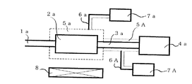
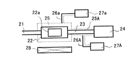
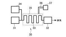
図1に示す表面清浄化装置は、ガスの流れ方向に沿って、高純度不活性ガス流入口1a、被表面清浄化物としての被表面清浄化部品2a、ガスサンプリング配管3a、高感度ガス分析装置4aの順序で構成され、被表面清浄化部品2aの外周部に加熱手段5aを備えるものである。加熱手段5aは、温度センサー6aを用いて温度調節器7aで温度を制御している。また、ガスサンプリング配管3aは、被表面清浄化部品2aから脱離した水分、有機物が再吸着しないように、外周部に加熱手段5Aを備え、温度センサー6Aを用いて温度調節器7Aで温度を制御している。また、被表面清浄化部品2aの下部には冷却ファン8が付いており、冷却時間を短縮出来るようになっている。
The surface cleaning apparatus shown in FIG. 1 includes a high purity inert gas inlet 1a, a
前記高純度不活性ガス流入口1aには、図示しない高純度不活性ガス供給源が接続されている。 A high purity inert gas supply source (not shown) is connected to the high purity inert gas inlet 1a.
被表面清浄化物としての前記被表面清浄化部品2aは、この実施の形態においては、内部に流路を有し当該内部流路の壁面を被清浄化表面とする物品のうちの部品、例えば、パイプ、バルブ、フィルタ等の配管部品となっている。もっとも、本実施の形態では、被表面清浄化物は、被表面清浄化部品2aに代えて、このような部品ではない前記物品、例えば、前記配管部品の組立体である配管等としてもよい。被表面清浄化物品2aは、金属材料、金属蒸着材料及び金属メッキ材料のうちのいずれかを、被清浄化表面の少なくとも一部を形成する部分に少なくとも有するものであってもよい。また、被表面清浄化物品2aは、可塑剤を有する樹脂材料又は可塑剤を有しない樹脂材料を、被清浄化表面の少なくとも一部を形成する部分に少なくとも有していてもよい。
In this embodiment, the surface-cleaning
本実施の形態では、被表面清浄化物品2aが内部流路(図示せず)を有し当該内部流路の壁面を被清浄化表面としていることから、前記内部流路の入口端に前記高純度不活性ガス流入口1aが接続されると共に、前記内部流路の出口端にガスサンプリング配管3aが接続されている。
In the present embodiment, the surface-cleaned
前記ガスサンプリング配管3aは、被表面清浄化部品2aのガス流路を通過したガスを高感度ガス分析装置4aに導くためのものであり、高感度ガス分析装置4aに導入されたガスは当該分析装置4aから外部に排気される。
The gas sampling pipe 3a is for guiding the gas that has passed through the gas flow path of the
前記高感度ガス分析装置4aは、導入されたガス中の不純物濃度を測定するための装置であり、例えば、大気圧イオン化質量分析装置(APIMS)や高圧イオン化質量分析装置(HPIMS)を用いることができる。
The high-
前記加熱手段5a,5Aは、それぞれ被表面清浄化部品2a及びガスサンプリング配管3aの外周部に設けられたヒータ等から構成されており、それぞれ温度センサー6a,6Aからの検出温度に基づいて、温度調節器7a,7Aにより制御されて、これら被表面清浄化部品2a及びガスサンプリング配管3aを直接的に加熱することにより、被表面清浄化部品2a(ひいては、その被清浄化表面である内部流路の壁面)及びガスサンプリング配管3aを所定温度に保持するようになっている。
The heating means 5a and 5A are each composed of a heater or the like provided on the outer peripheral portion of the surface-cleaned
前記加熱手段5a,5Aとしてのヒータは、例えばステンレスシーズヒータ等のワイヤ状のヒータやゴムタイプのヒータから構成されている。また前記温度センサー6a,6Aは、例えば熱電対から構成されている。
The heaters as the heating means 5a and 5A are composed of, for example, a wire heater such as a stainless steel heater or a rubber type heater. The
前記冷却ファン8は、図1に示す例では、被表面清浄化部品2aの下方に配設されており、冷却手段として、被表面清浄化部品2aを強制的に空冷するものである。
In the example shown in FIG. 1, the cooling fan 8 is disposed below the surface-cleaning
図2の実施の形態は、ガスサンプリング配管3bにガス切り替え手段9を備え、複数個の表面清浄化処理が行える表面清浄化装置で、ガスの流れ方向に沿って、高純度不活性ガス流入口1b、分岐管10を介して被表面清浄化部品2b、ガスサンプリング配管3b、順序で構成され、被表面清浄化部品2bの外周部に加熱手段5bを備えており、温度センサー6bを用いて温度調節器7bで温度を制御を行っている。また、図1の実施の形態と同様に、ガスサンプリング配管3bは、被表面清浄化部品2bから脱離した水分、有機物が再吸着しないように、外周部に加熱手段5Bを備え、温度センサー6Bを用いて温度調節器7Bで温度を制御している。さらに、ガスサンプリング配管3bにはガス切り替え手段9が付いており、一方の出口を大気に開放し、もう一方の出口が高感度ガス分析装置4bに接続されている。本実施の形態で説明したガス切り替え手段9は、複数個に別れたガス切り替え手段9を説明したが、図示は行わないが、複数個のガス切り替え流路を1個のガス切り替え手段9の中に備えた、ロータリー式ガス切り替えバルブを用いてもよい。なお、本実施の形態においても、被表面清浄化物品2bは、被表面清浄化物品2aと同様に、内部に流路を有し当該内部流路の壁面を被清浄化表面とする物品のうちの部品、例えば、配管部品とされている。
The embodiment shown in FIG. 2 is a surface cleaning apparatus that includes a gas switching means 9 in the gas sampling pipe 3b and can perform a plurality of surface cleaning processes. A high purity inert gas inlet along the gas flow direction. 1b, the surface-cleaning
前述した図1及び図2の各実施の形態によれば、図示しない高純度不活性ガス供給源から、高純度不活性ガス流入口1a,1bを介して、被表面清浄化部品2a,2bの内部に、高純度不活性ガス、例えばアルゴンガスが導入される。ここで、被表面清浄化部品2a,2bは、それぞれ加熱手段5a,5bにより加熱されて、所定温度に保持された状態において、被表面清浄化部品2a,2bの内部流路には、高純度不活性ガスが通流することになる。これにより、被表面清浄化部品2a,2bの内面に吸着されている水素、水分及び有機物等の不純物や樹脂部分中に含まれる可塑剤等の有機物(以下、不純物等)が脱離し、高純度不活性ガスによって希釈され、ガス流によって下流に流れて、被表面清浄化部品2a,2b内から速やかに排出される。なお、被表面清浄化物品2a,2bの内部流路の壁面(被清浄化表面)が高い温度に保持されていることから、不純物等の脱離効果が高まるのである。
According to each embodiment of FIG.1 and FIG.2 mentioned above, from the high purity inert gas supply source which is not illustrated, high purity inert gas inflow port 1a, 1b of surface-cleaning
この場合、加熱手段5a,5bの加熱による所定温度は、例えば被表面清浄化部品2a,2bの使用温度より10℃以上高い温度に設定され、被表面清浄化部品2a,2bが金属材料例えばステンレス鋼から成る場合には、水素の脱離ピークである350℃以上に設定される。
In this case, the predetermined temperature by heating of the heating means 5a and 5b is set to a temperature that is higher by 10 ° C. or more than the operating temperature of the surface-cleaned
その後、加熱手段5a,5bによる加熱が中断され、冷却ファン8が作動することにより、被表面清浄化部品2a,2bは、強制空冷され、室温まで戻される。このとき、被表面清浄化部品2a,2b内には、高純度不活性ガスが通流しているので、前述したように脱離した不純物等が冷却に伴って被表面清浄化部品2a,2bの内面に再付着するようなことが防止される。
Thereafter, heating by the heating means 5a and 5b is interrupted, and the cooling fan 8 is operated, whereby the surface-cleaned
なお、前記冷却ファン8は、強制空冷によって、被表面清浄化部品2a,2bの冷却を促進するためのものであり、省略されてもよい。冷却ファン8が省略された場合には、被表面清浄化部品2a,2bは、自然冷却によって、室温まで戻される。また、冷却ファン8による空冷の代わりに、冷却手段として、水冷方式等の他の方式の冷却手段も使用され得る。
The cooling fan 8 is for accelerating the cooling of the
そして、この高純度不活性ガスは、この被表面清浄化部品2a,2bを通流した後、ガスサンプリング配管3a,3bそしてガス切り替え手段9(図2の場合)を介して、高感度ガス分析装置4a,4b内に導入され、その不純物濃度が検出される。これにより、被表面清浄化部品2a,2bの不純物濃度の低下が測定され、表面清浄化が確認され得る。
The high-purity inert gas flows through the surface-cleaned
ここで、具体的な実験例を以下に示す。被表面清浄化部品2a,2bとして、直径1/4インチ、全長8mのステンレス配管を使用して、高純度不活性ガスとして不純物濃度1ppb以下の高純度アルゴンガスを約1リットル/分で通流させて、200℃にて約1時間処理を行なった。
Here, a specific experimental example is shown below. High-purity argon gas with an impurity concentration of 1 ppb or less is passed as a high-purity inert gas at a rate of about 1 liter / min using stainless steel pipes with a diameter of 1/4 inch and a total length of 8 m as the surface-cleaned
ここで、最初に被表面清浄化部品2a,2bの内面が200℃になったとき、即ち表面清浄化処理前における排出ガスを、高感度ガス分析装置4aとして大気圧イオン化質量分析装置(APIMS)を用いて分析したところ、図5(a)のグラフに示すような結果が得られた。図5(a)において、横軸は質量数(m/z)を示し、縦軸はイオン強度(A)を示す(後述する図5(b)も同様)。図5(a)のグラフから明らかなように、水分H2O及び有機物(例えばハイドロカーボン系有機物)が多量に検出されている。
Here, when the inner surfaces of the surface-cleaned
これに対して、表面清浄化処理後、即ち前記処理後に、一旦室温まで戻した後、再度200℃に加熱したとき、排出ガスの成分を分析したところ、図5(b)のグラフに示すような結果が得られた。図5(b)のグラフから明らかなように、水分H2Oの脱離が著しく低減し、有機物もほとんど検出されず、また図5(a)で全く見ることができなかった親イオンであるアルゴンイオンのピークも見られる等、被表面清浄化部品2a,2bの表面清浄化が確認された。
On the other hand, after the surface cleaning treatment, that is, after the treatment, when the temperature was once returned to room temperature and again heated to 200 ° C., the components of the exhaust gas were analyzed, as shown in the graph of FIG. Results were obtained. As is apparent from the graph of FIG. 5B, desorption of moisture H 2 O is remarkably reduced, organic substances are hardly detected, and it is a parent ion that cannot be seen at all in FIG. Surface cleaning of the surface-cleaned
これは、例えば図6(a)に示すように、被表面清浄化部品2a,2bの表面には、図示のように、ミクロ的に見ると、孔2eがあって、この孔2e内に、水素、水分や有機物等の不純物が入っている。これらの不純物が、前述した加熱手段5a,5bによる加熱によって膨張して、膨張した余分の不純物がこの孔2eから押し出されて脱離する。これにより、室温に戻されたとき、図6(b)に示すように、不純物が収縮すると共に、高純度不活性ガスを引き込むことになる。従って、孔2e内における不純物濃度が低下することにより、被表面清浄化部品2a,2bの表面が清浄化されるのである。このような原理は、被表面清浄化物品2a,2bの材質が、金属、樹脂(可塑剤を含んでいても含んでいなくても)などいずれの材質であっても、適用され得る。
For example, as shown in FIG. 6 (a), there are
なお、前述したように前記孔2e内に不純物が入っているので、高純度不活性ガスを通流させる前に、予め前記不純物を当該孔2eから追い出すように、被表面清浄化物品2a,2bの内部流路を、図示しない真空ポンプで真空引きしておくことが好ましい。
Since the
なお、被表面清浄化部品2a,2bが金属の場合、従来の真空中での加熱による表面処理やクロム酸化膜を作る表面処理においては、表面処理された被表面清浄化部品2a,2bの表面は、きつね色又は金色になるが、本発明による表面清浄化処理では、被表面清浄化部品2a,2bの表面は、金属光沢がそのまま現われるので、一見しただけで処理の違いが明白になる。
In the case where the surface-cleaned
さらに、図6(b)に示すように一度表面清浄化された被表面清浄化部品2a,2bが、再度加熱され高純度不活性ガスが通流された後、常温に戻されると、図6(c)に示すように、加熱によって不純物及び高純度不活性ガスが膨張して脱離し、その後常温に戻されたとき、再び高純度不活性ガスを引き込むことになるため、孔2e内における不純物濃度がより一層低下することになる。従って、高純度不活性ガスを通流させながらの加熱及び冷却を複数回繰り返すことによって、より不純物濃度の低い表面清浄化が達成されることになる。なお、この再度の高純度不活性ガスの通流しながらの加熱の前にも、被表面清浄化物品2a,2bの内部流路を、一旦、図示しない真空ポンプで真空引きしておくことが好ましい。
Further, as shown in FIG. 6B, once the surface-cleaned
なお、被表面清浄化物品2a,2bの全長が長い場合には、前記加熱手段5Aが、被表面清浄化物品2a,2bの内部流路に沿って複数部分に分割されていて、上流側から下流側に向かって順次に加熱を行なうように、制御されるようにしてもよい。あるいは、加熱領域の小さい加熱手段を用い、これを上流側から下流側にかけて移動させていってもよい。これにより、全長の長い被表面清浄化物品2a,2b全体が同時に加熱されて、その下流端における不純物濃度が高濃度になることが防止される。
When the entire length of the surface-cleaned
図3の実施の形態は、表面清浄化を行った後、大気に暴露させる事なく高純度不活性ガスを充満させて気密封じを行った表面清浄化部品(内部流路を有する物品)で、被表面清浄化部品2cの高純度不活性ガス流入口1cに、閉塞部材としてのオールメタルバルブ11cが取り付けられており、ガス流出口12cが閉塞部材としてのブラインドナット13c等で密閉されている。気密処理の行いかたは、まず、被表面清浄化部品2cの表面清浄化処理を行い、室温まで冷却した後、高純度不活性ガスを流しながら、ガス流出口12cをブラインドナット13cで閉めた後、最後にオールメタルバルブ11cを閉め、高純度不活性ガス流入口1cの対向面のオールメタルバルブ11cの接続口をガス供給系から取り外す。また、図示は行わないが、気密封じを行う、オールメタルバルブ11cは、ブラインドナットでもよい。
The embodiment of FIG. 3 is a surface cleaning component (article having an internal flow path) that is air-sealed by being filled with a high-purity inert gas without being exposed to the atmosphere after surface cleaning. An all-metal valve 11c as a closing member is attached to the high purity inert gas inlet 1c of the surface-cleaning
図4の実施の形態は、被表面清浄化部品2dの両端にオールメタルバルブ11d、11Dを備え、オールメタルバルブ11Dの他方の接続口に高圧の高純度不活性ガスを充満した高純度不活性ガス保有容器14を備えるものである。この高純度不活性ガス保有容器14は、表面清浄化部品の組み立て時に、高純度不活性ガスを放出(パージ)させながら組み立てを行うためのもので、大気の流入を防ぎながら組み立てを行うことが出来る。また、図示は行わないが、気密封じを行う、オールメタルバルブ11dは、ブラインドナットでもよい。
In the embodiment shown in FIG. 4, all-metal valves 11d and 11D are provided at both ends of the surface-cleaned component 2d, and the other connection port of the all-metal valve 11D is filled with high-pressure high-purity inert gas. A
図7の実施の態様は、被表面清浄化部品2a,2bが配管部品としてのパイプである場合(配管の場合でもよい)に、この被表面清浄化部品2a,2bの外面に沿って、加熱手段5aとしてのワイヤ状のヒータ及び温度センサー6aとしての熱電対を固定するためのクリップ部材15である。
In the embodiment of FIG. 7, when the surface-cleaned
このクリップ部材15は、バネ性を有しており、配管部品である被表面清浄化物品2a,2bを外周の一部(図7(b)では、上部)を除いて外周方向に包むとともに被表面清浄化物品2a,2bを挟持することにより、被表面清浄化物品2a,2bに対して固定されるものであり、さらに、ワイヤ状部材を被表面清浄化物品2a,2bの表面に当接した状態に保持する凹部15c,15dを有している。
The
本実施の形態では、クリップ部材15は、例えば、樹脂板や金属板等からなり、中間片15eと、該中間片15eの両側に連続して斜めに起立した両側片15a,15bとから構成されている。側片15aと中間片15eとの間の内側角部分、及び、側片15bとの間の内側角部分が、前記凹部15c,15dとなっている。図7に示す状態においては、両側片15a,15bが互いに近づく方向に自身のバネ性により付勢されており、これにより各片15a,15b,15eが被表面清浄化物品2a,2bの3箇所に当接して当該被表面清浄化物品2a,2bを挟持している。
In the present embodiment, the
ワイヤ状のヒータ5a及び熱電対6aは、配管部品である被表面清浄化部品2a,2bの長手方向に沿って、複数箇所にて、それぞれクリップ部材15によって、被表面清浄化部品2a,2bの外面に固定される。その際、クリップ部材15は、被表面清浄化部品2a,2bに対して、長手軸と垂直に押し込むことにより、両側片15a,15bが一旦外側に撓んだ後、被表面清浄化部品2a,2bを抱き込むように係合するので、容易に取り付けられ得る。
The
図8は、図1及び図2に示した表面清浄化装置に使用される高純度不活性ガス供給源の一構成例を示している。 FIG. 8 shows a configuration example of a high purity inert gas supply source used in the surface cleaning apparatus shown in FIGS. 1 and 2.
この場合、高純度不活性ガス供給源16は、ガスボンベ等のガス貯蔵源16aと、ガス貯蔵源16aからの高純度不活性ガスの圧力を調整するためのレギュレータ16bと、ガス流量を計測するためのガス流量計17と、ガスの不純物を除去する純化器18と、から構成されている。これにより、純化器18を介して、高純度不活性ガスが供給されるようになっている。
In this case, the high purity inert
これに対して、前記高純度不活性ガス供給源16は、図9に示すように、前述した純化器18の下流に、さらにヒータ19a及び温度調整器19bから成る加熱部19を備えていてもよい。
On the other hand, as shown in FIG. 9, the high purity inert
これにより、純化器18からの高純度不活性ガスは、図10に示すように、さらに加熱部19により例えば150℃に加熱された後、被表面清浄化部品2a,2b内に供給されることになる。この場合、被表面清浄化部品2a,2bの内部流路の壁面(被清浄化表面)は、加熱された高純度不活性ガスによって、間接的に加熱されることになるため、図1及び図2の表面清浄化装置における加熱手段5a,5bを省略してもよい。なお、図9に示す高純度不活性ガス供給源は、ヒータ19aを停止させれば加熱されていない高純度不活性ガスを供給することになるので、加熱された高純度不活性ガスと加熱されていない高純度不活性ガスとを切り換えて供給する手段を構成している。
Thereby, as shown in FIG. 10, the high purity inert gas from the
なお、加熱された高純度不活性ガスが導入される被表面清浄化部品2a,2bとして、図11に示すように、比較的長いガス流路を有する被表面清浄化物としての配管2fが使用される場合、好ましくは、配管2fの周りに、保温材20が配設されている。これにより、配管2fは、保温材20によって断熱されるので、配管2fを流れる高純度不活性ガスの放熱が低減され、配管2fの出口端付近における高純度不活性ガスの温度低下が抑制されることになる。
As shown in FIG. 11, a
図12の実施の態様による表面清浄化装置は、ガスの流れ方向に沿って、高純度不活性ガス流入口21、被表面清浄化物22aが収容される処理室22、ガスサンプリング配管23、高感度ガス分析装置24の順序で構成され、被表面清浄化物22aの外周部に加熱手段25aを備えるものである。加熱手段25aは、温度センサー26aを用いて温度調節器27aで温度を制御している。また、ガスサンプリング配管23aは、被表面清浄化物22aから脱離した水分、有機物が再吸着しないように、外周部に加熱手段25Aを備え、温度センサー26Aを用いて温度調節器27Aで温度を制御している。また、被表面清浄化物22aの下部には冷却ファン28が付いており、冷却時間を短縮出来るようになっている。
The surface cleaning apparatus according to the embodiment of FIG. 12 has a high-purity
前記図12に示す表面清浄化装置は、図1の表面清浄化装置に比較して、被表面清浄化物22aが処理室22内に収容されている点でのみ異なる構成になっている。
The surface cleaning apparatus shown in FIG. 12 is different from the surface cleaning apparatus shown in FIG. 1 only in that the
前記処理室22は、気密構造に構成されていると共に、内部空間が、被表面清浄化物22aを収容し得る大きさに形成されている。そして、処理室22は、その入口端に、前記高純度不活性ガス流入口21が接続されると共に、その出口端に、ガスサンプリング配管23が接続されている。
The
前記被表面清浄化物22aは、例えば金属材料から成る配管部品、例えばバルブ、フィルタだけでなく、磁気ディスク基板等のあらゆる材料から成る各種部品、さらには可塑剤を有する樹脂材料から成る樹脂製品、例えば半導体ウェハの保管容器、半導体装置の保持容器や、配管部品としてのパッキン等であってもよい。被表面清浄化物22aは、金属材料、金属蒸着材料及び金属メッキ材料のうちのいずれかを、被清浄化表面の少なくとも一部を形成する部分に少なくとも有するものであってもよい。被表面清浄化物22aは、可塑剤を有する樹脂材料又は可塑剤を有しない樹脂材料を、被清浄化表面の少なくとも一部を形成する部分に少なくとも有していてもよい。また、前記被表面清浄化物22aは、内部流路を有する物品であってもよいし、内部流路を有しない物品であってもよい。
The surface-cleaned
このような構成の表面清浄化装置によれば、図示しない高純度不活性ガス供給源から、高純度不活性ガス流入口21を介して、処理室22の内部に、高純度不活性ガス、例えばアルゴンガスが導入される。ここで、処理室22は、加熱手段25aにより加熱されて、所定温度に保持されているので、処理室22内に収容された被表面清浄化物22aの表面は、間接的にこの所定温度に保持されることになると共に、その外側の表面を高純度不活性ガスが通流することになる。これにより、被表面清浄化物22の表面に吸着されている水素、水分及び有機物等の不純物や樹脂材料中に含まれる可塑剤等の有機物(以下、不純物等)が脱離し、高純度不活性ガスによって希釈され、ガス流によって下流に流れて、処理室22から速やかに排出される。なお、被表面清浄化物品2a,2bの内部流路の壁面(被清浄化表面)が高い温度に保持されていることから、不純物等の脱離効果が高まるのである。
According to the surface cleaning apparatus having such a configuration, a high-purity inert gas, for example, from the high-purity inert gas supply source (not shown) to the inside of the
この場合、加熱手段25aの加熱による所定温度は、例えば被表面清浄化物22aの使用温度より10℃以上高い温度に設定されると共に、樹脂部品を構成する樹脂材料の耐熱温度を考慮して、この耐熱温度より低い温度に設定される。
In this case, the predetermined temperature due to heating of the heating means 25a is set to a temperature that is 10 ° C. or more higher than the operating temperature of the surface-cleaned
その後、加熱手段25aによる加熱が中断され、冷却ファン28が作動することにより、処理室22は、強制空冷され、室温まで戻される。このとき、処理室22内には、高純度不活性ガスが通流しているので、前述したように被表面清浄化物22aの表面から脱離した不純物等が冷却に伴って、処理室22の内面や被表面清浄化物22aの表面に再付着するようなことが防止される。
Thereafter, heating by the heating means 25a is interrupted, and the cooling
なお、前記冷却ファン28は、強制空冷によって、被表面清浄化物22aの冷却を促進するためのものであり、省略されてもよい。冷却ファン28が省略された場合には、被表面清浄化物22aは、自然冷却によって、室温まで戻される。また、冷却ファン28による空冷の代わりに、冷却手段として、水冷方式等の他の方式の冷却手段も使用され得る。
The cooling
そして、この高純度不活性ガスは、この処理室22を通流した後、ガスサンプリング配管23を介して、高感度ガス分析装置24内に導入され、その不純物濃度が検出される。これにより、被表面清浄化物22aの不純物濃度の低下が測定され、表面清浄化が確認され得る。
The high-purity inert gas flows through the
なお、本実施の形態においても、図1及び図2の各実施の形態と同様に、高純度不活性ガスを通流させながらの加熱及び冷却を複数回繰り返してもよい。また、本実施の形態においても、高純度不活性ガスを通流させる前に、予め処理室22を図示しない真空ポンプで真空引きしておくことが好ましい。
Also in the present embodiment, as in the embodiments of FIGS. 1 and 2, heating and cooling while allowing the high-purity inert gas to flow may be repeated a plurality of times. Also in the present embodiment, it is preferable to evacuate the
本実施の形態においても、図6を参照して説明した原理により表面の清浄化が行われる。 Also in this embodiment, the surface is cleaned by the principle described with reference to FIG.
前記被表面清浄化物22aが、可塑剤を有する樹脂材料を、被清浄化表面の少なくとも一部を形成する部分に少なくとも有しているもの、例えば、可塑剤を有する樹脂材料からなるパッキンやフィルタや半導体ウエハの保管容器などである場合には、図6を参照して説明した原理により表面の清浄化が行われるのみならず、次に説明するように、当該樹脂材料の表面側領域に含まれていた可塑剤が脱離される。
The surface-cleaned
すなわち、図13(a)に示すように、前記表面清浄化処理前には、樹脂部品である被表面清浄化物22aの内部に、可塑剤22bが均一に含まれている。そして、被表面清浄化物22aの表面領域における可塑剤22bが、前述した加熱手段25aによる加熱によって、図13(b)に示すように、被表面清浄化物22aの表面から脱離する。このとき、被表面清浄化物22aの可塑剤22bがあった部分には、高純度不活性ガスが入り込むことになる。その結果、当該被表面清浄化物22aの表面側の可塑剤の濃度が内部側の可塑剤の濃度より低くなる。これにより、被表面清浄化物22aの表面が清浄化されることになり、当該被表面清浄化物22aの使用時には可塑剤の脱離量が低減される。なお、この点は、前述した図1及び図2の各実施の形態においも、被表面清浄化物品2a,2bが、可塑剤を有する樹脂材料を、被清浄化表面の少なくとも一部を形成する部分に少なくとも有していれば、同様である。
That is, as shown in FIG. 13A, before the surface cleaning treatment, the
従って、例えば被表面清浄化物22aとして、樹脂部品である半導体ウェハの保管容器が使用される場合、従来は純水で洗うだけの表面清浄化処理によって、半導体ウェハを保管するために使用されており、保管容器に残る可塑剤によって半導体ウェハが汚染されていたが、前述した表面清浄化処理によって、その表面側領域の可塑剤が脱離された半導体ウェハの保管容器によれば、保管する半導体ウェハの可塑剤による汚染が確実に防止され得る。
Therefore, for example, when a semiconductor wafer storage container, which is a resin component, is used as the surface-cleaned
なお、本実施の形態においても、図8に示すような高純度不活性ガス供給源16に代えて、図9に示すような高純度不活性ガス供給源16を用い、加熱手段25aを省略してもよい。
Also in this embodiment, instead of the high purity inert
また、前記処理室22を容器として図1及び図2における被表面清浄化物品2a,2bと同様に取り扱えるようにしておけば、被表面清浄化物22を収容した当該容器に関して、図3の場合や図4の場合と同様の状態を実現することができる。
Further, if the
図14の実施の態様は、配管を有する半導体製造装置に関して、その配管を表面清浄化するようにした半導体製造装置である。すなわち、本実施の形態による半導体装置は、図1に示すような表面清浄化装置が組み込まれたものである。 The embodiment shown in FIG. 14 is a semiconductor manufacturing apparatus in which a surface of a semiconductor manufacturing apparatus having a pipe is cleaned. That is, the semiconductor device according to the present embodiment incorporates a surface cleaning apparatus as shown in FIG.
図14において、半導体製造装置30は、半導体装置の製造のために必要な処理ガスを供給する処理ガス供給源31と、半導体装置の製造プロセスが行われるプロセスチャンバ32と、処理ガス供給源31からの処理ガスをプロセスチャンバ32に導く配管33とを有している。
In FIG. 14, a
さらに、半導体製造装置30は、配管33にその上流側から高純度不活性ガスを導入する高純度不活性ガス供給源34と、配管33を加熱する加熱手段35とを備えている。プロセスチャンバ32は、配管の一種、すなわち、ガス流路構成部分であるので、プロセスチャンバ32を加熱する加熱手段を設けておいてもよい。
Further, the
前記ガス供給源34は、図8に示したガス供給源16と同じ構成を有している。また、加熱手段35は、例えばワイヤ状のヒータであって、図7に示したクリップ部材15によって、配管31の外面に沿って固定されていると共に、温度センサー36を用いて、温度調節器37で温度を制御している。
The
図面には示していないが、処理ガス供給源31から配管33へのガス供給と高純度不活性ガス供給源34からの配管33への高純度不活性ガス供給とは、切り換えて行うことができるようになっている。また、図面には示していないが、配管33を通流したガスを分析するための高感度ガス分析装置が設けられている。
Although not shown in the drawing, the gas supply from the processing
なお、ガス供給源34として、図9に示すガス供給源16と同じ構成を有するガス供給源を使用してもよく、この場合には、前記加熱手段35は省略され得る。この場合、好ましくは、配管33は、図11における配管2fと同様に、保温剤によって覆われる。
Note that a gas supply source having the same configuration as the
このような構成の半導体製造装置30によれば、まず配管33を含む半導体製造装置30が組み立てられた後に、半導体製造装置30の使用開始前に、配管33の表面清浄化処理が行なわれる。即ち、ガス供給源34から高純度不活性ガスが、半導体製造装置30の配管33内に導入されると共に、配管33は、加熱手段35により加熱され、所定温度に保持される。
According to the
その後、加熱手段35が遮断され、ガス供給源34からの高純度不活性ガスが通流された状態で、配管33が自然冷却され、室温に戻される。これにより、配管33の内面が表面清浄化されることになる。
Thereafter, the heating means 35 is shut off, and the
なお、本実施の形態においても、図1及び図2の各実施の形態と同様に、高純度不活性ガスを通流させながらの加熱及び冷却を複数回繰り返してもよい。また、本実施の形態においても、高純度不活性ガスを通流させる前に、予め配管33を図示しない真空ポンプで真空引きしておくことが好ましい。 Also in the present embodiment, as in the embodiments of FIGS. 1 and 2, heating and cooling while allowing the high-purity inert gas to flow may be repeated a plurality of times. Also in the present embodiment, it is preferable to evacuate the piping 33 in advance with a vacuum pump (not shown) before flowing the high purity inert gas.
室温の高純度不活性ガスを単に流すだけの従来の表面清浄化処理では、配管33の内面が清浄化されるまでに1か月以上を要していたのに対して、本実施の形態による半導体製造装置30においては、約1日の表面清浄化処理によって、配管33の内面が清浄化され得る。
In the conventional surface cleaning process in which a high-purity inert gas at room temperature is simply flowed, it takes one month or more until the inner surface of the
さらに、前記半導体製造装置30においては、使用によって配管33内面に不純物等が付着した場合、再び前述した表面清浄化処理が行なわれることによって、不純物等が除去される。このような表面清浄化処理が定期的にあるいは不定期に行なわれる。この場合、配管33への加熱手段33の固定とガス供給源32、図示しない高感度ガス分析装置の接続は、半導体製造装置30の使用の際にもそのままにしておいてもよく、また表面清浄化処理を行なう毎に、行なうようにしてもよい。
Further, in the
このように、前記半導体製造装置30によれば、使用時に前記配管を通流する処理ガス中の不純物が低減され、半導体製造の歩留りが向上するなどの利点が得られる。
As described above, according to the
また、前記半導体製造装置30においては、配管33は比較的長いガス流路を有している。このため、前記加熱手段33が、配管33のガス流路に沿って複数部分に分割されていて、上流側から下流側に向かって順次に加熱を行なうように、制御されるようにしてもよい。あるいは、加熱領域の小さい加熱手段を用い、これを上流側から下流側にかけて移動させていってもよい。これにより、配管33全体が同時に加熱されて、その下流端における不純物濃度が高濃度になることが防止される。
In the
以上、本発明の各実施の形態について説明したが、本発明はこれらの実施の形態に限定されるものではない。 Although the embodiments of the present invention have been described above, the present invention is not limited to these embodiments.
1a,1b,1c 高純度不活性ガス流入口
2a,2b,2c,2d 被表面清浄化部品
2e 孔
3a,3b ガスサンプリング配管
4a,4b 高感度ガス分析装置
5a,5A,5b,5B 加熱手段
6a,6A,6b,6B 温度センサー
7a,7A,7b,7B 温度調節器
8 冷却ファン
9 ガス切り替え手段
10 分岐管
11c,11d オールメタルバルブ
12 ガス流出口
13c ブラインドナット
14 高純度不活性ガス保有容器
15 クリップ部材
16 ガス供給源
16a ガス貯蔵源
16b レギュレータ
17 流量計
18 純化器
19 加熱部
20 保温材
21 高純度不活性ガス流入口
22 被表面清浄化部品
23 ガスサンプリング配管
24 高感度ガス分析装置
25a,25A 加熱手段
26a,26A 温度センサー
27a,27A 温度調節器
28 冷却ファン
30 半導体製造装置
31 処理ガス供給源
32 プロセスチャンバ
33 配管
34 高感度ガス分析装置
35 加熱手段
36 温度センサー
37 温度調整器
1a, 1b, 1c High-purity
Claims (12)
前記表面清浄化部品は、所定の表面清浄化を行った後、大気に暴露させる事なく高純度不活性ガスを充満させて気密封じを行ったものであり、
前記所定の表面清浄化は、高純度ガス供給部品において、ガス流路内に高純度不活性ガスを通流させた状態で、被表面清浄化部品の外周部より昇温加熱を行った後、室温まで冷却して、実質的に酸化膜を形成させる事なく、ガス流路内に吸着している水素、水分、有機物の吸着量を低減させる表面清浄化方法である、
ことを特徴とする表面清浄化部品の施工方法。 When assembling a plurality of surface cleaning parts, it is a construction method of a surface cleaning part that performs assembly from the upstream side to the downstream side along the gas flow direction while flowing a high purity inert gas,
The surface-cleaning component is one that has been air-sealed by filling a high-purity inert gas without exposing it to the atmosphere after performing predetermined surface cleaning.
In the high-purity gas supply component, the predetermined surface cleaning is performed by heating and heating from the outer peripheral portion of the surface-cleaning component in a state where a high-purity inert gas is passed through the gas flow path. It is a surface cleaning method that reduces the adsorption amount of hydrogen, moisture, and organic substances adsorbed in the gas flow path without substantially forming an oxide film by cooling to room temperature.
A method of constructing a surface cleaning component characterized by the above.
前記表面清浄化部品は、所定の表面清浄化を行った後、大気に暴露させる事なく高純度不活性ガスを充満させて気密封じを行ったものであり、
前記所定の表面清浄化は、高純度不活性ガスを通流させた雰囲気で、金属材料、金属蒸着材料、乃至金属メッキ材料のいずれかを、少なくとも一部に有する被表面清浄化部品を昇温加熱した後、室温まで冷却して、実質的に酸化膜を形成させることなく、表面の水素濃度を低減させる表面清浄化方法である、
ことを特徴とする表面清浄化部品の施工方法。 When assembling a plurality of surface cleaning parts, it is a construction method of a surface cleaning part that performs assembly from the upstream side to the downstream side along the gas flow direction while flowing a high purity inert gas,
The surface-cleaning component is one that has been subjected to air-sealing by filling a high-purity inert gas without exposing it to the atmosphere after performing predetermined surface cleaning.
The predetermined surface cleaning is performed by raising the temperature of a surface cleaning component having at least a part of any one of a metal material, a metal deposition material, and a metal plating material in an atmosphere in which a high-purity inert gas is passed. It is a surface cleaning method that reduces the hydrogen concentration on the surface without substantially forming an oxide film after heating and cooling to room temperature.
A method for constructing a surface cleaning component characterized by that.
前記表面清浄化部品は、所定の表面清浄化を行った後、大気に暴露させる事なく高純度不活性ガスを充満させて気密封じを行ったものであり、
前記所定の表面清浄化は、高純度ガス供給部品において、ガス流路内に高純度不活性ガスを通流させた状態で、被表面清浄化部品の外周部より昇温加熱を行った後、室温まで冷却して、実質的に酸化膜を形成させる事なく、ガス流路内に吸着している水素、水分、有機物の吸着量を低減させる表面清浄化方法である、
ことを特徴とする表面清浄化部品の施工方法。 A surface cleaning part is manufactured at a surface cleaning processing factory, transported to the site using transportation means, and assembled on site.
The surface-cleaning component is one that has been subjected to air-sealing by filling a high-purity inert gas without exposing it to the atmosphere after performing predetermined surface cleaning.
In the high-purity gas supply component, the predetermined surface cleaning is performed by heating and heating from the outer peripheral portion of the surface-cleaning component with the high-purity inert gas flowing in the gas flow path, It is a surface cleaning method that reduces the amount of adsorption of hydrogen, moisture, and organic matter adsorbed in the gas flow path without substantially forming an oxide film by cooling to room temperature.
A method for constructing a surface cleaning component characterized by that.
前記表面清浄化部品は、所定の表面清浄化を行った後、大気に暴露させる事なく高純度不活性ガスを充満させて気密封じを行ったものであり、
前記所定の表面清浄化は、高純度不活性ガスを通流させた雰囲気で、金属材料、金属蒸着材料、乃至金属メッキ材料のいずれかを、少なくとも一部に有する被表面清浄化部品を昇温加熱した後、室温まで冷却して、実質的に酸化膜を形成させることなく、表面の水素濃度を低減させる表面清浄化方法である、
ことを特徴とする表面清浄化部品の施工方法。 A surface cleaning part is manufactured at a surface cleaning processing factory, transported to the site using transportation means, and assembled on site.
The surface-cleaning component is one that has been subjected to air-sealing by filling a high-purity inert gas without exposing it to the atmosphere after performing predetermined surface cleaning.
The predetermined surface cleaning is performed by raising the temperature of a surface cleaning component having at least a part of any one of a metal material, a metal deposition material, and a metal plating material in an atmosphere in which a high-purity inert gas is passed. It is a surface cleaning method that reduces the hydrogen concentration on the surface without substantially forming an oxide film after heating and cooling to room temperature.
A method for constructing a surface cleaning component characterized by that.
前記表面清浄化物は、内部に流路を有し当該内部流路の壁面を清浄化表面とする物品であり、所定の表面清浄化方法が行われた後に、前記内部流路を大気に暴露させることなく前記内部流路内に高純度不活性ガスを充満させて前記内部流路の気密封じを行ったものであり、
前記所定の表面清浄化方法は、ガス流路内に前記被表面清浄化物の被清浄化表面が露出し、前記被表面清浄化物の前記被清浄化表面が高い温度に保持された状態で、前記ガス流路内に高純度不活性ガスを通流させる第1の段階を備えた、
ことを特徴とする表面清浄化部品の施工方法。 When assembling multiple surface cleaning products, each of which is a component of piping equipment, surface cleaning is performed from the upstream side to the downstream side along the gas flow direction while flowing high purity inert gas. A construction method for parts,
The surface-cleaned product is an article having a flow path inside and having the wall surface of the internal flow path as a cleaned surface, and after the predetermined surface cleaning method is performed, the internal flow path is exposed to the atmosphere. Without filling the internal flow path with a high purity inert gas and sealing the internal flow path,
In the predetermined surface cleaning method, the surface to be cleaned of the surface cleaning object is exposed in the gas flow path, and the surface to be cleaned of the surface cleaning object is maintained at a high temperature. Comprising a first stage for passing a high purity inert gas through the gas flow path;
A method for constructing a surface cleaning component characterized by that.
前記表面清浄化物は、所定の表面清浄化方法が行われた後に、当該表面清浄化物を大気に暴露させることなく前記内部に高純度不活性ガスを充満させた容器内に収容して前記容器の気密封じを行ったものであり、
前記所定の表面清浄化方法は、ガス流路内に前記被表面清浄化物の被清浄化表面が露出し、前記被表面清浄化物の前記被清浄化表面が高い温度に保持された状態で、前記ガス流路内に高純度不活性ガスを通流させる第1の段階を備えた、
ことを特徴とする表面清浄化部品の施工方法。 When assembling multiple surface cleaning products, each of which is a component of piping equipment, surface cleaning is performed from the upstream side to the downstream side along the gas flow direction while flowing high purity inert gas. A construction method for parts,
The surface-cleaned product is stored in a container filled with a high-purity inert gas without exposing the surface-cleaned product to the atmosphere after a predetermined surface cleaning method is performed. It was air-tight and
In the predetermined surface cleaning method, the surface to be cleaned of the surface cleaning object is exposed in the gas flow path, and the surface to be cleaned of the surface cleaning object is maintained at a high temperature. Comprising a first stage for passing a high purity inert gas through the gas flow path;
A method for constructing a surface cleaning component characterized by that.
Priority Applications (1)
| Application Number | Priority Date | Filing Date | Title |
|---|---|---|---|
| JP2007069672A JP4394131B2 (en) | 1996-08-08 | 2007-03-17 | Surface cleaning component construction method |
Applications Claiming Priority (2)
| Application Number | Priority Date | Filing Date | Title |
|---|---|---|---|
| JP24094596 | 1996-08-08 | ||
| JP2007069672A JP4394131B2 (en) | 1996-08-08 | 2007-03-17 | Surface cleaning component construction method |
Related Parent Applications (1)
| Application Number | Title | Priority Date | Filing Date |
|---|---|---|---|
| JP22716597A Division JP3964502B2 (en) | 1996-08-08 | 1997-08-08 | Surface cleaning method and apparatus, surface cleaned product, and semiconductor manufacturing apparatus |
Publications (2)
| Publication Number | Publication Date |
|---|---|
| JP2007184635A true JP2007184635A (en) | 2007-07-19 |
| JP4394131B2 JP4394131B2 (en) | 2010-01-06 |
Family
ID=38340366
Family Applications (1)
| Application Number | Title | Priority Date | Filing Date |
|---|---|---|---|
| JP2007069672A Expired - Lifetime JP4394131B2 (en) | 1996-08-08 | 2007-03-17 | Surface cleaning component construction method |
Country Status (1)
| Country | Link |
|---|---|
| JP (1) | JP4394131B2 (en) |
Cited By (2)
| Publication number | Priority date | Publication date | Assignee | Title |
|---|---|---|---|---|
| JP2014002119A (en) * | 2012-06-20 | 2014-01-09 | Nippon Api Corp | Method for creating calibration curve and destructive testing apparatus |
| JP2018166170A (en) * | 2017-03-28 | 2018-10-25 | 東京エレクトロン株式会社 | Substrate processor, substrate processing method and storage medium |
-
2007
- 2007-03-17 JP JP2007069672A patent/JP4394131B2/en not_active Expired - Lifetime
Cited By (2)
| Publication number | Priority date | Publication date | Assignee | Title |
|---|---|---|---|---|
| JP2014002119A (en) * | 2012-06-20 | 2014-01-09 | Nippon Api Corp | Method for creating calibration curve and destructive testing apparatus |
| JP2018166170A (en) * | 2017-03-28 | 2018-10-25 | 東京エレクトロン株式会社 | Substrate processor, substrate processing method and storage medium |
Also Published As
| Publication number | Publication date |
|---|---|
| JP4394131B2 (en) | 2010-01-06 |
Similar Documents
| Publication | Publication Date | Title |
|---|---|---|
| KR100478550B1 (en) | Molecular Contamination Control System | |
| Berman | Water vapor in vacuum systems | |
| US6605134B2 (en) | Method and apparatus for collecting rare gas | |
| TWI412620B (en) | Methods and apparatus for cleaning semiconductor manufacturing tool | |
| JP4112659B2 (en) | Noble gas recovery method and apparatus | |
| JP2768952B2 (en) | Metal oxidation treatment apparatus and metal oxidation treatment method | |
| JP3677211B2 (en) | Buffer chamber and integration method for integrating both physical vapor deposition chamber and chemical vapor deposition chamber into a processing system | |
| US12249494B2 (en) | Remote plasma cleaning of chambers for electronics manufacturing systems | |
| JPH07169729A (en) | Device and method for performing cleaning or/and tool surface in semiconductor manufacture by using nitrogen trifluoride | |
| JP3964502B2 (en) | Surface cleaning method and apparatus, surface cleaned product, and semiconductor manufacturing apparatus | |
| JP4394131B2 (en) | Surface cleaning component construction method | |
| TW202539296A (en) | Method for removing residual charges from electrostatic chucks and semiconductor process equipment | |
| JPH113867A (en) | Semiconductor manufacturing equipment | |
| JP2002054799A (en) | Impurity removing method for high-pressure gas vessel | |
| JP2004109072A (en) | Method for analyzing metal impurities in liquid | |
| JP3844999B2 (en) | Substrate processing method | |
| JP2002102638A (en) | Chemical filter | |
| JP5985265B2 (en) | Destructive inspection device and method of using the same | |
| JP2002025995A (en) | Vertical heat treatment equipment | |
| TW591737B (en) | Method of sampling contaminants on the inside of a semiconductor wafer carrier | |
| JPS6345822A (en) | Method and apparatus for cleaning | |
| JPH04215429A (en) | semiconductor manufacturing equipment | |
| JP2012114281A (en) | Method for manufacturing soi wafer | |
| JP2006004985A (en) | Substrate processing equipment | |
| JPH11258218A (en) | Analysis equipment |
Legal Events
| Date | Code | Title | Description |
|---|---|---|---|
| TRDD | Decision of grant or rejection written | ||
| A01 | Written decision to grant a patent or to grant a registration (utility model) |
Free format text: JAPANESE INTERMEDIATE CODE: A01 Effective date: 20090929 |
|
| A01 | Written decision to grant a patent or to grant a registration (utility model) |
Free format text: JAPANESE INTERMEDIATE CODE: A01 |
|
| A61 | First payment of annual fees (during grant procedure) |
Free format text: JAPANESE INTERMEDIATE CODE: A61 Effective date: 20091014 |
|
| R150 | Certificate of patent or registration of utility model |
Free format text: JAPANESE INTERMEDIATE CODE: R150 |
|
| FPAY | Renewal fee payment (event date is renewal date of database) |
Free format text: PAYMENT UNTIL: 20121023 Year of fee payment: 3 |
|
| FPAY | Renewal fee payment (event date is renewal date of database) |
Free format text: PAYMENT UNTIL: 20121023 Year of fee payment: 3 |
|
| FPAY | Renewal fee payment (event date is renewal date of database) |
Free format text: PAYMENT UNTIL: 20131023 Year of fee payment: 4 |
|
| R250 | Receipt of annual fees |
Free format text: JAPANESE INTERMEDIATE CODE: R250 |
|
| R250 | Receipt of annual fees |
Free format text: JAPANESE INTERMEDIATE CODE: R250 |
|
| R250 | Receipt of annual fees |
Free format text: JAPANESE INTERMEDIATE CODE: R250 |
|
| EXPY | Cancellation because of completion of term |