JP2007183885A - Print controller, printer, printing system, and printing method - Google Patents
Print controller, printer, printing system, and printing method Download PDFInfo
- Publication number
- JP2007183885A JP2007183885A JP2006002942A JP2006002942A JP2007183885A JP 2007183885 A JP2007183885 A JP 2007183885A JP 2006002942 A JP2006002942 A JP 2006002942A JP 2006002942 A JP2006002942 A JP 2006002942A JP 2007183885 A JP2007183885 A JP 2007183885A
- Authority
- JP
- Japan
- Prior art keywords
- printing
- information
- control apparatus
- methods
- Prior art date
- Legal status (The legal status is an assumption and is not a legal conclusion. Google has not performed a legal analysis and makes no representation as to the accuracy of the status listed.)
- Pending
Links
Images


Abstract
Description
本発明は、印刷制御装置、印刷装置、印刷システム、及び印刷方法に関する。 The present invention relates to a print control apparatus, a printing apparatus, a printing system, and a printing method.
デジタルカメラ等の記録再生装置と、プリンタとを直接的に接続したり、又は一体的に構成したりして、記録された画像を印刷する機器がある。 There is a device that prints a recorded image by directly connecting a recording / reproducing apparatus such as a digital camera and a printer, or by integrally configuring the printer.
また、特許文献1では、複数のプリンタを内蔵した複合プリンタがモノクロページと、カラーページとを自動的に判別して、それぞれのページの印刷に最適なプリンタで印刷を行う技術が記述されている。
しかしながら、複数のプリンタを内蔵した複合プリンタと、印刷制御可能な例えばカメラとを接続して印刷する場合、カメラを操作する使用者が印刷を行うプリンタやその方式を任意に選択することができない問題があった。 However, when printing is performed by connecting a composite printer having a plurality of printers and, for example, a camera capable of printing control, the user who operates the camera cannot arbitrarily select the printer and the method for printing. was there.
本発明は前記の問題点に鑑みなされたもので、印刷制御装置を操作する使用者が、印刷装置が対応している複数の印刷方式の中から任意の印刷方式を選択可能にすることを目的とする。 SUMMARY An advantage of some aspects of the invention is that a user who operates a printing control apparatus can select an arbitrary printing method from a plurality of printing methods supported by the printing apparatus. And
そこで、前記問題を解決するため、本発明は、印刷装置を制御する印刷制御装置であって、前記印刷装置が対応している少なくとも2つ以上の印刷方式の情報を取得する印刷方式情報取得手段と、前記印刷方式情報取得手段が取得した前記情報に応じて、前記印刷装置が対応している少なくとも2つ以上の印刷方式の選択に係る画面を表示する印刷方式選択画面表示手段と、前記画面を介した選択操作指示に基づいて、前記印刷装置における印刷方法を決定する印刷方式決定手段と、を有することを特徴とする。 Accordingly, in order to solve the above problem, the present invention provides a printing control apparatus that controls a printing apparatus, and obtains information on at least two printing methods supported by the printing apparatus. Printing method selection screen display means for displaying a screen related to selection of at least two or more printing methods supported by the printing apparatus according to the information acquired by the printing method information acquisition means, and the screen And a printing method determining means for determining a printing method in the printing apparatus based on a selection operation instruction via the printing apparatus.
また、本発明は、印刷を行う印刷装置であって、対応している少なくとも2つ以上の印刷方式の情報を印刷制御装置に提供する印刷方式情報提供手段と、対応している少なくとも2つ以上の印刷方式の内、前記印刷制御装置において決定された印刷方式に基づいて、印刷を行う印刷手段と、を有することを特徴とする。 Further, the present invention is a printing apparatus that performs printing, and at least two or more corresponding printing method information providing means for providing information of at least two or more corresponding printing methods to the printing control apparatus. And printing means for performing printing based on the printing method determined by the printing control apparatus.
また、前記問題を解決するため、本発明は、印刷システム、印刷制御方法、及び印刷方法としてもよい。 In order to solve the above problem, the present invention may be a printing system, a printing control method, and a printing method.
本発明によれば、印刷制御装置を操作する使用者が、印刷装置が対応している複数の印刷方式の中から任意の印刷方式を選択可能にすることができる。 According to the present invention, a user who operates a print control apparatus can select an arbitrary print system from a plurality of print systems supported by the print apparatus.
以下、本発明の実施例について図面に基づいて説明する。 Embodiments of the present invention will be described below with reference to the drawings.
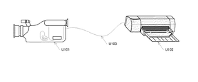
図1は、カメラ一体型VTRと、複合プリンタとで構成されるプリントシステムのシステム構成図である。U101は、通信部を備えた民生用デジタルVTR規格に準じた液晶モニタ付きのカメラ一体型VTRを表す。U102は、記録画像を視認可能にプリントする複数の印刷部を備えた複合プリンタを表す。カメラ一体型VTR U101及び複合プリンタU102は、U103の通信ケーブルで接続される。この構成により、カメラ一体型VTR U101と、複合プリンタU102との間で命令やデータの受け渡しを行い、カメラ一体型VTR U101に記録された記録画像を複合プリンタU102で印刷を行う。 FIG. 1 is a system configuration diagram of a print system including a camera-integrated VTR and a composite printer. U101 represents a camera-integrated VTR with a liquid crystal monitor that conforms to a consumer digital VTR standard equipped with a communication unit. U102 represents a composite printer including a plurality of printing units that print a recorded image so as to be visible. The camera-integrated VTR U101 and the composite printer U102 are connected by a communication cable U103. With this configuration, commands and data are exchanged between the camera-integrated VTR U101 and the composite printer U102, and a recorded image recorded on the camera-integrated VTR U101 is printed by the composite printer U102.
なお、カメラ一体型VTR U101と、複合プリンタU102との接続は、ケーブルに限らず無線通信方式によって通信を行ってもよい。 The connection between the camera-integrated VTR U101 and the composite printer U102 is not limited to a cable, and communication may be performed by a wireless communication method.
図2は、カメラ一体型VTRの機能ブロック図である。図2において、B100は、各ブロックの制御信号線や、各ブロックへのデータの送受に使用するアドレスバスやデータバスを表す。B101は、マイクロコンピュータを表し、カメラ一体型VTR全体を制御する。B102は、画像信号処理部を表し、B105の光電変換素子で被写体を光電変換した画像信号や、B106の外部入出力コネクタから入力された画像信号や、B107のマイクから入力されB108の音声信号処理部で処理された音声信号を処理する。また、画像信号処理部B102は、B110の表示制御部によってB109の液晶パネルに表示するための画像を処理する。 FIG. 2 is a functional block diagram of the camera-integrated VTR. In FIG. 2, B100 represents a control signal line of each block, and an address bus and a data bus used for data transmission / reception to each block. B101 represents a microcomputer and controls the entire camera-integrated VTR. B102 represents an image signal processing unit. An image signal obtained by photoelectrically converting a subject with the photoelectric conversion element B105, an image signal input from an external input / output connector B106, or an audio signal process B108 input from a microphone B107 The audio signal processed by the unit is processed. The image signal processing unit B102 processes an image to be displayed on the liquid crystal panel B109 by the display control unit B110.
B115は、レンズ部を表し、B116のレンズ制御部によって制御される。また、B124は、B105、B115、B116を包含する撮像部である。B103は、メモリを表し、一時的なデータの記憶を行う。B114は、電源制御部を表し、B112のACアダプタやB113のバッテリ等の電源制御を行う。B111は、入力スイッチ類を表し、電源ボタンや撮影開始ボタン、再生画像の選択ボタン等から構成される。 B115 represents a lens unit, and is controlled by the lens control unit of B116. B124 is an imaging unit including B105, B115, and B116. B103 represents a memory and stores temporary data. B114 represents a power supply control unit, and performs power supply control of the AC adapter of B112, the battery of B113, and the like. B111 represents input switches, and includes a power button, a shooting start button, a playback image selection button, and the like.
B123は、通信制御部を表し、B122の通信コネクタを介して接続された機器(プリンタやPC)との通信を行う。B118は、VTR制御部を表し、B119のVTR部の制御と、動画像データ及び音声の記録と、再生とを制御する。B117は、メモリカードコントローラを表し、B120のメモリカードの書き込みと、読み出しとを制御する。 B123 represents a communication control unit, and performs communication with a device (printer or PC) connected via the communication connector of B122. B118 represents a VTR control unit, and controls the control of the VTR unit of B119, recording and reproduction of moving image data and audio, and playback. B117 represents a memory card controller and controls writing and reading of the memory card of B120.
図3は、複合プリンタの機能ブロック図である。図3に示される複合プリンタは、プリンタ本体内部に、レザープリンタ機能と、インクジェット(以下IJ)プリンタ機能と、昇華型プリンタ機能とを有する。また、複合プリンタは、前記三方式のプリンタ機能を有することを印刷制御装置(例えば、カメラ一体型VTR等)に通信によって通知する機能を有する。また、複合プリンタは、印刷制御装置から指定された印刷方式や印刷設定に従って印刷可能な機能も有する。 FIG. 3 is a functional block diagram of the composite printer. The composite printer shown in FIG. 3 has a leather printer function, an ink jet (hereinafter referred to as IJ) printer function, and a sublimation printer function inside the printer body. In addition, the composite printer has a function of notifying a print control apparatus (for example, a camera-integrated VTR) that the printer has the three types of functions by communication. The composite printer also has a function capable of printing in accordance with a printing method and print settings designated by the print control apparatus.
図3において、U310は、複合プリンタ内部の制御ユニットを表す。U320は、制御ユニットによって制御される複合プリンタ内部のレーザープリンタユニットを表す。U330は、制御ユニットによって制御される複合プリンタ内部のIJプリンタユニットを表す。U340は、制御ユニットによって制御される複合プリンタ内部の昇華型プリンタユニットを表す。 In FIG. 3, U310 represents a control unit inside the composite printer. U320 represents a laser printer unit inside the composite printer controlled by the control unit. U330 represents an IJ printer unit inside the composite printer controlled by the control unit. U340 represents a sublimation type printer unit inside the composite printer controlled by the control unit.
以下、U310の制御ユニットを構成する機能ブロックについて説明する。B312は、電源制御部を表し、B311のACコネクタ部から供給されるAC電源と、B313のバッテリ部から供給されるDC電源との制御を行う。B315は、マイクロコンピュータ部を表し、マイクロコンピュータによって複合プリンタ全体の制御を行う。B314は、スイッチ部を表し、複合プリンタ本体の操作ボタンの情報をマイクロコンピュータ部に入力する。B316は、通信部を表し、ケーブル接続や無線通信接続による他の通信可能機器との命令やデータの受け渡しを行い、他の通信可能機器に記録された記録画像を印刷する。 Hereinafter, functional blocks constituting the control unit of U310 will be described. B312 represents a power supply control unit, and controls AC power supplied from the AC connector unit of B311 and DC power supplied from the battery unit of B313. B315 represents a microcomputer unit, which controls the entire composite printer by the microcomputer. B314 represents a switch unit, and inputs information on operation buttons of the composite printer main body to the microcomputer unit. B316 represents a communication unit, transfers commands and data to and from other communicable devices via cable connection or wireless communication connection, and prints recorded images recorded on the other communicable devices.
以下、U320のレーザープリンタユニットを構成する機能ブロックについて説明する。B321は、レーザープリントエンジンを表し、B322のトナーと、B323のペーパー制御部1とを制御すると共に、レーザープリンタユニット全体を制御する。また、ペーパー制御部1は、B324のペーパートレイ1を制御し、紙の給紙及び排紙を制御する。
Hereinafter, functional blocks constituting the laser printer unit of U320 will be described. B321 represents a laser print engine, which controls the toner of B322 and the
以下、U330のIJプリンタユニットを構成する機能ブロックについて説明する。B331は、IJプリントエンジンを表し、B332のIJインクと、B323のペーパー制御部1とを制御すると共に、IJプリンタユニット全体を制御する。ペーパー制御部1と、ペーパートレイ1とは、レーザープリンタユニットと共通の機能ブロックで、レーザープリンタユニットと同様に機能する。
Hereinafter, functional blocks constituting the IJ printer unit of U330 will be described. B331 represents an IJ print engine, and controls the IJ ink of B332 and the
以下、U340の昇華型プリンタユニットを構成する機能ブロックについて説明する。B342は、昇華型プリントエンジンを表し、B343の昇華型インクと、B341のペーパー制御部2とを制御すると共に、昇華型プリントユニット全体を制御する。また、ペーパー制御部2は、B344のペーパートレイ2を制御し、紙の給紙及び排紙を制御する。
The functional blocks constituting the U340 sublimation printer unit will be described below. B342 represents a sublimation print engine, which controls the sublimation ink of B343 and the
図4は、印刷制御装置の印刷動作に関わる主要ブロック図である。B404は、プリンタ情報記憶部を表し、複合プリンタとの通信によって得られる複合プリンタの複数の印刷方式を記憶する。印刷制御装置を操作する使用者が、B405の操作スイッチ部と、B402の表示部とによって印刷方式を選択/決定すると、選択された印刷方式等が、複合プリンタに通知され、複合プリンタにおいて印刷が実行される。B406の印刷制御部は、決定された印刷方式と、B401の印刷画像記録部に格納されている画像と、をB403の通信部を通じてプリンタに要求する。 FIG. 4 is a main block diagram relating to the printing operation of the printing control apparatus. B404 represents a printer information storage unit, and stores a plurality of printing methods of the composite printer obtained by communication with the composite printer. When a user operating the print control apparatus selects / determines a printing method using the operation switch unit B405 and the display unit B402, the selected printing method is notified to the composite printer, and printing is performed in the composite printer. Executed. The print control unit in B406 requests the printer for the determined printing method and the image stored in the print image recording unit in B401 through the communication unit in B403.
図5は、印刷制御装置の制御を行うマイクロコンピュータ(印刷制御部)における制御の一例を示すフローチャート(その1)である。なお、以下の説明において、フローチャートの各ステップを"S"と略す。図5のフローチャートでは、印刷制御装置の印刷動作について説明する。 FIG. 5 is a flowchart (part 1) illustrating an example of control in a microcomputer (print control unit) that controls the print control apparatus. In the following description, each step of the flowchart is abbreviated as “S”. With reference to the flowchart of FIG. 5, the printing operation of the print control apparatus will be described.
S101は、通信開始を表し、通信ケーブルの接続や、印刷制御装置や複合プリンタの起動、通信モードへの遷移等によって通信が開始される。 S101 represents the start of communication, and communication is started by connection of a communication cable, activation of a print control device or a composite printer, transition to a communication mode, or the like.
S102では、印刷制御装置は、通信によって複合プリンタから指定可能な印刷方式(レーザープリント、IJプリント、昇華型プリント)や、同じく通信によって相手から指定可能な各印刷方式での印刷設定等のプリンタの情報を複合プリンタから取得する。ここで、印刷設定とは、印刷画像の情報(ファイル形式、ファイルサイズ等)、印刷枚数、印刷用紙のサイズ(印刷範囲)、印刷位置(レイアウト)、印刷品質(画質)、印刷用紙の種類(紙質)、インクの種類、印刷効果(特殊効果)、画像の加工情報等である。 In S102, the print control apparatus determines a printer method such as a print method (laser print, IJ print, sublimation print) that can be designated from a composite printer by communication, or a print setting in each print method that can be designated from the other party by communication. Get information from the compound printer. Here, the print settings include print image information (file format, file size, etc.), number of copies, print paper size (print range), print position (layout), print quality (image quality), print paper type ( Paper quality), ink type, printing effect (special effect), image processing information, and the like.
或いは、印刷制御装置は、予め規定された複合プリンタ固有のコードを取得することで、接続された複合プリンタを判別し、自身の記憶部(メモリ)等より、プリンタの情報を取得する。 Alternatively, the print control apparatus determines a connected composite printer by acquiring a predetermined code specific to the composite printer, and acquires printer information from its own storage unit (memory) or the like.
S103では、印刷制御装置は、接続された複合プリンタが持つ印刷方式を表示する(例えば、図6等参照。)。S104では、印刷制御装置は、印刷制御装置を操作する使用者が、図6に示されるような画面において選択した選択操作等に応じて、印刷方式を選択、決定する。 In step S103, the print control apparatus displays the printing method of the connected composite printer (see, for example, FIG. 6). In S104, the print control apparatus selects and determines a print method according to a selection operation or the like selected on the screen as shown in FIG. 6 by the user operating the print control apparatus.
S105では、印刷制御装置は、選択した印刷方式で指定可能な印刷設定画面を表示する(例えば、図7等参照。)。S106では、印刷制御装置は、印刷制御装置を操作する使用者が、図7に示されるような画面において選択した選択操作等に応じて、印刷設定を選択、決定する。 In S105, the print control apparatus displays a print setting screen that can be specified by the selected printing method (see, for example, FIG. 7). In S <b> 106, the print control apparatus selects and determines print settings in accordance with the selection operation selected on the screen as shown in FIG. 7 by the user operating the print control apparatus.
S107では、印刷制御装置は、決定した印刷方式と、印刷設定と、印刷対象の画像(又は文書)と、を複合プリンタに送信し、印刷を要求する。 In step S107, the print control apparatus transmits the determined printing method, print setting, and image (or document) to be printed to the composite printer, and requests printing.
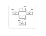
図8は、印刷制御装置の操作スイッチ部の一例を示す図である。図8において、B501は、SETボタンを表し、図5のS104やS106等において、使用者に押されることによって決定を意味する。B502〜B505は、方向ボタンを表し、図5のS104や、S105、S106において使用者に押されることによって、表示画面のUIカーソルを押されたボタンの方向に移動する。また、図5のS106においては、図7の各設定項目上にカーソルを合わせた状態で使用者がB504又はB505を押すことによって、表示されている設定値以外に選択肢がある場合には、他の設定値が印刷制御装置によって表示される。 FIG. 8 is a diagram illustrating an example of an operation switch unit of the print control apparatus. In FIG. 8, B501 represents a SET button, which means determination by being pressed by the user in S104 and S106 of FIG. B502 to B505 represent direction buttons, and the UI cursor on the display screen is moved in the direction of the pressed button when pressed by the user in S104 of FIG. 5, S105, or S106. In S106 of FIG. 5, when the user presses B504 or B505 with the cursor positioned on each setting item of FIG. 7, there are other options other than the displayed setting values. Are displayed by the print control apparatus.
印刷制御装置の使用者は、例えば複数の画像を1枚の用紙に印刷するインデックスプリントを行いたい場合は、IJプリント方式を選択する。また、印刷制御装置の使用者は、例えば1枚の画像を1枚の用紙に印刷する通常の印刷を行いたい場合は、昇華型プリント方式を選択する。 The user of the print control apparatus selects the IJ print method, for example, when performing index printing for printing a plurality of images on one sheet. Also, the user of the print control apparatus selects the sublimation type printing method when, for example, normal printing for printing one image on one sheet is desired.
このように、実施例1によれば、印刷制御装置の使用者は、プリント形態に応じて、プリント方式を適応的に選ぶことができる。 As described above, according to the first embodiment, the user of the printing control apparatus can adaptively select the printing method according to the printing mode.
実施例1では、印刷制御装置の一例として、カメラ一体型VTRを用いて説明を行った。実施例2では、印刷制御装置の一例として、携帯電話等の通信機器を用いて説明を行う。なお、実施例2では、主に実施例1と異なる点を説明する。 The first embodiment has been described using a camera-integrated VTR as an example of a print control apparatus. In the second embodiment, a description is given using a communication device such as a mobile phone as an example of a print control apparatus. In the second embodiment, differences from the first embodiment will be mainly described.
図9は、携帯電話等の通信機器と、複合プリンタとで構成されるプリントシステムのシステム構成図である。U201は、携帯電話等の通信機器を表す。U202は、記録画像を視認可能にプリントする複数の印刷部を備えた複合プリンタを表す。携帯電話等の通信機器U201及び複合プリンタU202は、U203の通信ケーブルで接続される。この構成により、携帯電話等の通信機器U201と、複合プリンタU202との間で命令やデータの受け渡しを行い、携帯電話等の通信機器U201に記録された記録画像を複合プリンタU202で印刷を行う。 FIG. 9 is a system configuration diagram of a print system including a communication device such as a mobile phone and a composite printer. U201 represents a communication device such as a mobile phone. U202 represents a composite printer including a plurality of printing units that print a recorded image so as to be visible. A communication device U201 such as a mobile phone and a composite printer U202 are connected by a communication cable U203. With this configuration, commands and data are exchanged between the communication device U201 such as a mobile phone and the composite printer U202, and a recorded image recorded on the communication device U201 such as a mobile phone is printed by the composite printer U202.
なお、携帯電話等の通信機器U201と、複合プリンタU202との接続は、ケーブルに限らず無線通信方式によって通信を行ってもよい。 Note that the connection between the communication device U201 such as a mobile phone and the composite printer U202 is not limited to a cable, and communication may be performed by a wireless communication method.
図10は、携帯電話等の通信機器の機能ブロック図である。図10において、B201は、マイクロコンピュータを表し、携帯電話等の通信機器全体を制御する。B202は、数字や文字、記号を入力するためのテンキーを表す。B203は、電源投入のための電源スイッチを表す。B204は、表示モニタとしての液晶画面を表す。B205は、バッテリを表し、携帯電話等の通信機器本体の駆動電源となる。B206は、無線通信に必要な回路で構成される無線通信モジュールを表し、B208のアンテナを用いて通信を行う。B207は、メモリを表し、データ等の一時記憶に使用する。B208は、複合プリンタとの通信コネクタを表す。 FIG. 10 is a functional block diagram of a communication device such as a mobile phone. In FIG. 10, B201 represents a microcomputer and controls the entire communication device such as a mobile phone. B202 represents a numeric keypad for inputting numbers, letters, and symbols. B203 represents a power switch for turning on the power. B204 represents a liquid crystal screen as a display monitor. B205 represents a battery and serves as a drive power source for a communication device main body such as a mobile phone. B206 represents a wireless communication module including circuits necessary for wireless communication, and performs communication using the antenna of B208. B207 represents a memory and is used for temporary storage of data and the like. B208 represents a communication connector with the composite printer.
上述した実施例では、印刷制御装置において印刷方式を1つ選択した場合の例を用いて説明を行った。実施例3では、印刷制御装置において印刷方式を複数選択した場合を例に説明を行う。なお、実施例3では、主に上述した実施例と異なる点を説明する。 In the above-described embodiment, the description has been given using an example in which one print method is selected in the print control apparatus. In the third embodiment, a case where a plurality of printing methods are selected in the print control apparatus will be described as an example. In the third embodiment, differences from the above-described embodiment will be mainly described.
図11は、印刷制御装置の制御を行うマイクロコンピュータ(印刷制御部)における制御の一例を示すフローチャート(その2)である。なお、以下の説明において、フローチャートの各ステップを"S"と略す。図11のフローチャートでは、印刷制御装置の印刷動作について説明する。 FIG. 11 is a flowchart (part 2) illustrating an example of control in the microcomputer (print control unit) that controls the print control apparatus. In the following description, each step of the flowchart is abbreviated as “S”. With reference to the flowchart of FIG. 11, the printing operation of the printing control apparatus will be described.
S201は、通信開始を表し、通信ケーブルの接続や、印刷制御装置やプリンタの起動、通信モードへの遷移等によって通信が開始される。 S201 represents the start of communication, and communication is started by connection of a communication cable, activation of a print control apparatus or printer, transition to a communication mode, or the like.
S202では、印刷制御装置は、通信によってプリンタから指定可能な印刷方式(レーザープリント、IJプリント、昇華型プリント)や、同じく通信によって相手から指定可能な各印刷方式での印刷設定等のプリンタの情報を複合プリンタから取得する。 In step S202, the print control apparatus determines printer information such as a printing method (laser printing, IJ printing, sublimation printing) that can be designated from the printer through communication, or print settings in each printing method that can be designated from the other party through communication. Is acquired from the composite printer.
或いは、印刷制御装置は、予め規定された複合プリンタ固有のコードを取得することで、接続された複合プリンタを判別し、自身の記憶部(メモリ)等より、プリンタの情報を取得する。 Alternatively, the print control apparatus determines a connected composite printer by acquiring a predetermined code specific to the composite printer, and acquires printer information from its own storage unit (memory) or the like.
S203では、印刷制御装置は、接続された複合プリンタが持つ印刷方式を表示する(例えば、図12等参照。)。図12に示されるように、実施例3の場合、印刷制御装置は、S102において取得したプリンタの情報に基づいて、複合プリンタが対応している印刷方式と、複合プリンタが対応している印刷方式の組み合わせと、を表示する。なお、説明の簡略化のため、実施例3では、印刷制御装置は、印刷方式の組み合わせとして、2つの印刷方式の組み合わせのみを表示するものとして説明を行う。以下の実施例においても同様である。なお、このことは本発明の実施を制限するものではない。 In step S203, the print control apparatus displays the print method of the connected composite printer (see, for example, FIG. 12). As illustrated in FIG. 12, in the case of the third embodiment, the print control apparatus, based on the printer information acquired in S <b> 102, print methods supported by the composite printer and print methods supported by the composite printer. And a combination of For the sake of simplification of explanation, in the third embodiment, the print control apparatus will be described assuming that only a combination of two printing methods is displayed as a combination of printing methods. The same applies to the following embodiments. Note that this does not limit the implementation of the present invention.
S204では、印刷制御装置は、印刷制御装置を操作する使用者が、図12に示されるような画面において選択した選択操作等に応じて、印刷方式を選択、決定する。S205では、印刷制御装置は、S204において複数印刷方式を選択、決定したか否かを判定する。印刷制御装置は、複数印刷方式を選択したと判定すると、S206に進み、一つの印刷方式を選択したと判定すると、S208に進む。 In step S204, the print control apparatus selects and determines a print method according to a selection operation or the like selected on the screen as illustrated in FIG. 12 by the user who operates the print control apparatus. In S205, the print control apparatus determines whether or not a plurality of printing methods have been selected and determined in S204. If the printing control apparatus determines that a plurality of printing methods have been selected, the process proceeds to S206. If the printing control apparatus determines that one printing method has been selected, the process proceeds to S208.
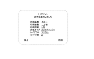
S206では、印刷制御装置は、例えば、印刷対象のデータ(又は情報)毎の印刷方式選択画面を表示する(例えば、図13等参照。)。図13では、印刷制御装置を操作する使用者が、画像部分を昇華型プリント方式でプリントし、日付やファイル名等の画像の端や余白部分にプリントする属性情報をIJプリント方式でプリントするよう選択した例が示されている。
このようにすることで、画像部分は黒の階調性を優先させて、属性情報の文字部分は精細さを求めるなどが可能になる。
もちろん、印刷方式の組合せはこれに限らないが、ユーザが求める画質等に応じて、適応的に選択できるようにすることで、ユーザの利便性を高めることができる。
In S206, for example, the printing control apparatus displays a printing method selection screen for each piece of data (or information) to be printed (see, for example, FIG. 13). In FIG. 13, the user who operates the print control apparatus prints the image portion by the sublimation printing method, and prints the attribute information to be printed on the edge or margin portion of the image such as the date and the file name by the IJ printing method. A selected example is shown.
By doing so, it is possible to give priority to black gradation in the image portion and to obtain fineness in the character portion of the attribute information.
Of course, the combination of printing methods is not limited to this, but user convenience can be enhanced by enabling adaptive selection according to the image quality desired by the user.
S207では、印刷制御装置は、印刷制御装置を操作する使用者が、図13に示されるような画面において選択した選択操作等に応じて、印刷対象のデータ(又は情報)毎の印刷方式を選択、決定する。 In step S207, the print control apparatus selects a print method for each data (or information) to be printed according to a selection operation selected on the screen as illustrated in FIG. 13 by the user operating the print control apparatus. ,decide.
S208では、印刷制御装置は、選択した印刷方式で指定可能な印刷設定画面を表示する。S209では、印刷制御装置は、印刷制御装置を操作する使用者が、印刷設定画面において選択した選択操作等に応じて、印刷設定を選択、決定する。 In step S208, the print control apparatus displays a print setting screen that can be specified by the selected printing method. In step S209, the print control apparatus selects and determines print settings according to a selection operation or the like selected on the print setting screen by the user who operates the print control apparatus.
S210では、印刷制御装置は、決定した印刷方式と、印刷設定と、印刷対象の画像(又は文書)と、を複合プリンタに送信し、印刷を要求する。 In step S210, the print control apparatus transmits the determined printing method, print setting, and image (or document) to be printed to the composite printer, and requests printing.
実施例3によれば、印刷制御装置の使用者は、プリント形態に応じて、複数のプリント方式を適応的に選んで、印刷等を行うことができる。 According to the third embodiment, the user of the print control apparatus can perform printing or the like by adaptively selecting a plurality of print methods according to the print form.
実施例3では、図11のS205〜S207及び、図13に示したように、印刷対象のデータ(又は情報)毎の印刷方式を、印刷制御装置を操作する使用者に選択させる例を用いて説明を行った。実施例4では、印刷制御装置が印刷対象のデータ(又は情報)毎の印刷方式を決定する場合を例に説明を行う。なお、実施例4では、主に上述した実施例と異なる点を説明する。 In the third embodiment, as shown in S205 to S207 of FIG. 11 and FIG. 13, an example in which the user who operates the print control apparatus selects a printing method for each data (or information) to be printed is used. I explained. In the fourth embodiment, a case where the print control apparatus determines a printing method for each piece of data (or information) to be printed will be described as an example. In the fourth embodiment, differences from the above-described embodiment will be mainly described.
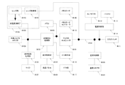
図14は、印刷制御装置の制御を行うマイクロコンピュータ(印刷制御部)における制御の一例を示すフローチャート(その3)である。なお、以下の説明において、フローチャートの各ステップを"S"と略す。図14のフローチャートでは、印刷制御装置の印刷動作について説明する。 FIG. 14 is a flowchart (part 3) illustrating an example of control in the microcomputer (print control unit) that controls the print control apparatus. In the following description, each step of the flowchart is abbreviated as “S”. In the flowchart of FIG. 14, the printing operation of the print control apparatus will be described.
図14のS301〜S304は、図11のS201〜S204と同様である。S305では、印刷制御装置は、S304において複数印刷方式を選択、決定したか否かを判定する。印刷制御装置は、複数印刷方式を選択したと判定すると、S306に進み、一つの印刷方式を選択したと判定すると、S307に進む。 S301 to S304 in FIG. 14 are the same as S201 to S204 in FIG. In S305, the print control apparatus determines whether or not a plurality of printing methods have been selected and determined in S304. If the printing control apparatus determines that a plurality of printing methods have been selected, the process proceeds to S306. If the printing control apparatus determines that one printing method has been selected, the process proceeds to S307.
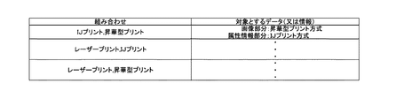
S306では、印刷制御装置は、S304において選択、決定した印刷方式の組み合わせに基づいて、メモリ等に保持している対応付けテーブル(例えば、図15参照)を参照し、対応する印刷方式毎の対象データ(又は情報)を決定する。なお、図15に示されるように、対応付けテーブルは、印刷方式の組み合わせと、組み合わせに係る印刷方式の印刷対象のデータ(又は情報)とを対応付けるテーブルである。 In step S306, the print control apparatus refers to a correspondence table (for example, see FIG. 15) held in a memory or the like based on the combination of printing methods selected and determined in step S304. Determine data (or information). As shown in FIG. 15, the association table is a table that associates a combination of printing methods with data (or information) to be printed by the printing method associated with the combination.
S307では、印刷制御装置は、選択した印刷方式で指定可能な印刷設定画面を表示する。S308では、印刷制御装置は、印刷制御装置を操作する使用者が、印刷設定画面において選択した選択操作等に応じて、印刷設定を選択、決定する。 In step S307, the print control apparatus displays a print setting screen that can be specified by the selected print method. In step S308, the print control apparatus selects and determines print settings according to a selection operation selected on the print setting screen by the user operating the print control apparatus.
S309では、印刷制御装置は、決定した印刷方式と、印刷設定と、印刷対象の画像(又は文書)と、を複合プリンタに送信し、印刷を要求する。 In step S309, the print control apparatus transmits the determined print method, print setting, and image (or document) to be printed to the composite printer, and requests printing.
実施例4では、印刷制御装置が、図15に示したような対応付けテーブルを有し、印刷方式の組み合わせに基づいて、対応する印刷方式毎の対象データ(又は情報)を決定した。実施例5では、複合プリンタが、図15に示したような対応付けテーブルを有し、印刷方式の組み合わせに基づいて、対応する印刷方式毎の対象データ(又は情報)を決定する例を説明する。 In the fourth embodiment, the print control apparatus has an association table as illustrated in FIG. 15 and determines target data (or information) for each corresponding printing method based on a combination of printing methods. In the fifth embodiment, an example will be described in which the composite printer has a correspondence table as illustrated in FIG. 15 and determines target data (or information) for each corresponding printing method based on a combination of printing methods. .
なお、実施例5の場合、印刷制御装置における処理を示すフローチャートは、実施例1の図5と同様である。但し、実施例5の場合、印刷制御装置は、S105において、複数の印刷方式で共通する印刷設定の画面を表示する。ここで、複数の印刷方式で共通する印刷設定とは、例えば、印刷枚数や、印刷用紙等である。 In the case of the fifth embodiment, the flowchart showing the processing in the print control apparatus is the same as FIG. 5 of the first embodiment. However, in the case of the fifth embodiment, the print control apparatus displays a print setting screen common to a plurality of printing methods in S105. Here, the print settings common to a plurality of printing methods are, for example, the number of prints and print paper.
図16は、複合プリンタの制御を行うマイクロコンピュータ(プロセッサ)における制御の一例を示すフローチャートである。なお、以下の説明において、フローチャートの各ステップを"S"と略す。図16のフローチャートでは、複合プリンタの印刷動作について説明する。 FIG. 16 is a flowchart illustrating an example of control in a microcomputer (processor) that controls the composite printer. In the following description, each step of the flowchart is abbreviated as “S”. With reference to the flowchart of FIG. 16, the printing operation of the composite printer will be described.
S401は、通信開始を表し、通信ケーブルの接続や、印刷制御装置や複合プリンタの起動、通信モードへの遷移等によって通信が開始される。 S401 represents the start of communication, and communication is started by connection of a communication cable, activation of a print control device or a composite printer, transition to a communication mode, or the like.
S402では、複合プリンタは、通信によって、印刷制御装置が指定可能な印刷方式(レーザープリント、IJプリント、昇華型プリント)や、印刷制御装置が指定可能な各印刷方式での印刷設定等のプリンタの情報を印刷制御装置に送信する。 In step S <b> 402, the composite printer determines a printer method such as a print method (laser print, IJ print, sublimation type print) that can be designated by the print control device or a print setting in each print method that can be designated by the print control device. Information is transmitted to the printing control apparatus.
S403では、複合プリンタは、印刷制御装置より、印刷制御装置において決定された印刷方式や、印刷設定、印刷対象の画像(又は文書)を含む、印刷要求を受信したか否かを判定する。複合プリンタは、印刷制御装置より、印刷要求を受信したと判定すると、S404に進み、印刷要求を受信していないと判定すると、S403の処理を繰り返す。 In step S <b> 403, the composite printer determines whether a print request including the print method determined by the print control apparatus, print settings, and an image (or document) to be printed is received from the print control apparatus. If it is determined that a print request has been received from the print control apparatus, the multifunction printer proceeds to S404. If it is determined that a print request has not been received, the multifunction printer repeats the process of S403.
S404では、複合プリンタは、印刷制御装置より受信した印刷要求に含まれる印刷方式等に基づいて、複数の印刷方式を選択されているか否かを判定する。複合プリンタは、複数の印刷方式が選択されていると判定すると、S405に進み、一つの印刷方式が選択されている判定すると、S406に進む。 In step S404, the composite printer determines whether a plurality of printing methods are selected based on the printing method included in the print request received from the print control apparatus. If the multi-function printer determines that a plurality of printing methods are selected, the process proceeds to S405. If it is determined that one printing method is selected, the process proceeds to S406.
S405では、複合プリンタは、印刷要求に含まれる、印刷制御装置において決定された印刷方式の組み合わせに基づいて、メモリ等に保持している対応付けテーブル(例えば、図15参照)を参照し、対応する印刷方式毎の対象データ(又は情報)を決定する。 In step S405, the composite printer refers to a correspondence table (for example, see FIG. 15) held in a memory or the like based on the combination of printing methods determined in the print control apparatus included in the print request. The target data (or information) for each printing method to be determined is determined.
S406では、複合プリンタは、印刷方式と、印刷設定と、印刷対象の画像(又は文書)と等に基づいて、印刷を開始する。 In step S <b> 406, the composite printer starts printing based on the printing method, the print setting, the image (or document) to be printed, and the like.
なお、図16のS404及びS405の処理を省略したフローチャートが、上述した各実施例における複合プリンタのフローチャートである。 A flowchart in which the processing of S404 and S405 in FIG. 16 is omitted is a flowchart of the composite printer in each of the above-described embodiments.
以上、上述した各実施例によれば、印刷制御装置を操作する使用者が、印刷装置が対応している複数の印刷方式の中から任意の印刷方式を選択可能にすることができる。 As described above, according to each of the above-described embodiments, a user operating the print control apparatus can select an arbitrary printing method from a plurality of printing methods supported by the printing apparatus.
以上、本発明の好ましい実施例について詳述したが、本発明は係る特定の実施例に限定されるものではなく、特許請求の範囲に記載された本発明の要旨の範囲内において、種々の変形・変更が可能である。 The preferred embodiments of the present invention have been described in detail above, but the present invention is not limited to such specific embodiments, and various modifications can be made within the scope of the gist of the present invention described in the claims.・ Change is possible.
例えば、上述した実施例では、印刷制御装置は、印刷方式や印刷設定等の情報を同一のステップにおいて、複合プリンタより取得するよう説明を行ったが、印刷方式と、印刷設定とを必要に応じてその都度複合プリンタより取得するようにしてもよい。 For example, in the above-described embodiment, the print control apparatus has been described to acquire information such as the print method and print settings from the composite printer in the same step. However, the print method and print settings are set as necessary. It may be obtained from the composite printer each time.
B401 印刷画像記録部
B402 表示部
B403 通信部
B404 プリンタ情報記憶部
B405 操作スイッチ部
B406 印刷制御部
B401 Print image recording unit B402 Display unit B403 Communication unit B404 Printer information storage unit B405 Operation switch unit B406 Print control unit
Claims (15)
前記印刷装置が対応している少なくとも2つ以上の印刷方式の情報を取得する印刷方式情報取得手段と、
前記印刷方式情報取得手段が取得した前記情報に応じて、前記印刷装置が対応している少なくとも2つ以上の印刷方式の選択に係る画面を表示する印刷方式選択画面表示手段と、
前記画面を介した選択操作指示に基づいて、前記印刷装置における印刷方法を決定する印刷方式決定手段と、
を有することを特徴とする印刷制御装置。 A printing control device for controlling a printing device,
Printing method information acquisition means for acquiring information of at least two printing methods supported by the printing apparatus;
Printing method selection screen display means for displaying a screen related to selection of at least two or more printing methods supported by the printing apparatus in accordance with the information acquired by the printing method information acquisition means;
A printing method determining means for determining a printing method in the printing apparatus based on a selection operation instruction via the screen;
A printing control apparatus comprising:
前記印刷設定情報取得手段が取得した前記情報に応じて、印刷設定に係る画面を表示する印刷設定画面表示手段と、
前記画面を介した選択操作指示に基づいて、印刷設定を決定する印刷設定決定手段と、
を更に有することを特徴とする請求項1乃至3の何れか1項に記載の印刷制御装置。 Print setting information acquisition means for acquiring information relating to print settings for each of at least two or more printing methods supported by the printing apparatus;
Print setting screen display means for displaying a screen relating to print settings in accordance with the information acquired by the print setting information acquisition means;
Print setting determination means for determining print settings based on a selection operation instruction via the screen;
The print control apparatus according to claim 1, further comprising:
対応している少なくとも2つ以上の印刷方式の情報を印刷制御装置に提供する印刷方式情報提供手段と、
対応している少なくとも2つ以上の印刷方式の内、前記印刷制御装置において決定された印刷方式に基づいて、印刷を行う印刷手段と、
を有することを特徴とする印刷装置。 A printing device that performs printing,
Printing method information providing means for providing the printing control apparatus with information on at least two printing methods that are compatible;
A printing unit that performs printing based on a printing method determined by the printing control apparatus among at least two printing methods that are compatible; and
A printing apparatus comprising:
前記印刷手段は、対応している少なくとも2つ以上の印刷方式の内、前記印刷制御装置において決定された印刷方式と、前記印刷制御装置において決定された印刷設定と、に基づいて、印刷を行うことを特徴とする請求項5乃至7の何れか1項に記載の印刷装置。 A print setting information providing means for providing the print control apparatus with information relating to print settings for each of at least two or more compatible printing methods;
The printing unit performs printing based on a printing method determined by the print control device and a print setting determined by the print control device among at least two corresponding printing methods. The printing apparatus according to claim 5, wherein the printing apparatus is a printer.
前記印刷制御装置は、
前記印刷装置が対応している少なくとも2つ以上の印刷方式の情報を取得する印刷方式情報取得手段と、
前記印刷方式情報取得手段が取得した前記情報に応じて、前記印刷装置が対応している少なくとも2つ以上の印刷方式の選択に係る画面を表示する印刷方式選択画面表示手段と、
前記画面を介した選択操作指示に基づいて、前記印刷装置における印刷方法を決定する印刷方式決定手段と、
を有し、
前記印刷装置は、
対応している少なくとも2つ以上の印刷方式の情報を印刷制御装置に提供する印刷方式情報提供手段と、
対応している少なくとも2つ以上の印刷方式の内、前記印刷制御装置において決定された印刷方式に基づいて、印刷を行う印刷手段と、
を有することを特徴とする印刷システム。 A printing system including a printing device and a printing control device,
The print control device includes:
Printing method information acquisition means for acquiring information of at least two printing methods supported by the printing apparatus;
Printing method selection screen display means for displaying a screen related to selection of at least two or more printing methods supported by the printing apparatus in accordance with the information acquired by the printing method information acquisition means;
A printing method determining means for determining a printing method in the printing apparatus based on a selection operation instruction via the screen;
Have
The printing apparatus includes:
Printing method information providing means for providing the printing control apparatus with information on at least two printing methods that are compatible;
A printing unit that performs printing based on a printing method determined by the printing control apparatus among at least two printing methods that are compatible; and
A printing system comprising:
前記印刷装置が対応している少なくとも2つ以上の印刷方式の情報を取得する印刷方式情報取得ステップと、
前記印刷方式情報取得ステップにおいて取得した前記情報に応じて、前記印刷装置が対応している少なくとも2つ以上の印刷方式の選択に係る画面を表示する印刷方式選択画面表示ステップと、
前記画面を介した選択操作指示に基づいて、前記印刷装置における印刷方法を決定する印刷方式決定ステップと、
を有することを特徴とする印刷制御方法。 A printing control method in a printing control apparatus for controlling a printing apparatus,
A printing method information obtaining step for obtaining information of at least two printing methods supported by the printing apparatus;
A printing method selection screen display step for displaying a screen related to selection of at least two or more printing methods supported by the printing device in accordance with the information acquired in the printing method information acquisition step;
A printing method determining step for determining a printing method in the printing apparatus based on a selection operation instruction via the screen;
A printing control method characterized by comprising:
対応している少なくとも2つ以上の印刷方式の情報を印刷制御装置に提供する印刷方式情報提供ステップと、
対応している少なくとも2つ以上の印刷方式の内、前記印刷制御装置において決定された印刷方式に基づいて、印刷を行う印刷ステップと、
を有することを特徴とする印刷方法。 A printing method in a printing apparatus that performs printing,
A printing method information providing step of providing information of at least two or more printing methods corresponding to the printing control device;
A printing step for performing printing based on a printing method determined in the printing control apparatus among at least two printing methods that are compatible; and
A printing method characterized by comprising:
昇華型方式で印刷を行う第1印刷部と、
インクジェット方式で印刷を行う第2印刷部と、
前記画像データ及び前記文字情報を、それぞれ前記第1印刷部又は前記第2印刷部で印刷するように制御する制御部と
を有することを特徴とする印刷装置。 An input unit for inputting image data and character information related to the image data;
A first printing section that performs printing by a sublimation type method;
A second printing unit that performs printing by an inkjet method;
And a control unit that controls the image data and the character information to be printed by the first printing unit or the second printing unit, respectively.
昇華型方式で印刷を行う第1印刷工程と、
インクジェット方式で印刷を行う第2印刷工程と、
を有し、
前記画像データ及び前記文字情報を、それぞれ前記第1印刷工程又は前記第2印刷工程で印刷するように制御する制御工程を更に有することを特徴とする印刷方法。 An input step of inputting image data and character information relating to the image data;
A first printing step for printing by a sublimation type method;
A second printing step for printing by an inkjet method;
Have
A printing method further comprising a control step of controlling the image data and the character information to be printed in the first printing step or the second printing step, respectively.
Priority Applications (2)
| Application Number | Priority Date | Filing Date | Title |
|---|---|---|---|
| JP2006002942A JP2007183885A (en) | 2006-01-10 | 2006-01-10 | Print controller, printer, printing system, and printing method |
| US11/613,711 US8351071B2 (en) | 2006-01-10 | 2006-12-20 | Print control apparatus, print apparatus, print system, print method, and storage medium |
Applications Claiming Priority (1)
| Application Number | Priority Date | Filing Date | Title |
|---|---|---|---|
| JP2006002942A JP2007183885A (en) | 2006-01-10 | 2006-01-10 | Print controller, printer, printing system, and printing method |
Publications (2)
| Publication Number | Publication Date |
|---|---|
| JP2007183885A true JP2007183885A (en) | 2007-07-19 |
| JP2007183885A5 JP2007183885A5 (en) | 2009-02-26 |
Family
ID=38339909
Family Applications (1)
| Application Number | Title | Priority Date | Filing Date |
|---|---|---|---|
| JP2006002942A Pending JP2007183885A (en) | 2006-01-10 | 2006-01-10 | Print controller, printer, printing system, and printing method |
Country Status (1)
| Country | Link |
|---|---|
| JP (1) | JP2007183885A (en) |
Cited By (1)
| Publication number | Priority date | Publication date | Assignee | Title |
|---|---|---|---|---|
| JP2014221516A (en) * | 2013-05-13 | 2014-11-27 | シャープ株式会社 | Image forming apparatus |
Citations (3)
| Publication number | Priority date | Publication date | Assignee | Title |
|---|---|---|---|---|
| JPH07148999A (en) * | 1993-12-01 | 1995-06-13 | Canon Inc | Printing device |
| JPH0969034A (en) * | 1995-08-31 | 1997-03-11 | Canon Inc | Information processor, printing device and printing system, and substitute printing method of printing system |
| JP2003154737A (en) * | 2001-11-22 | 2003-05-27 | Riso Kagaku Corp | Print engine controller and program |
-
2006
- 2006-01-10 JP JP2006002942A patent/JP2007183885A/en active Pending
Patent Citations (3)
| Publication number | Priority date | Publication date | Assignee | Title |
|---|---|---|---|---|
| JPH07148999A (en) * | 1993-12-01 | 1995-06-13 | Canon Inc | Printing device |
| JPH0969034A (en) * | 1995-08-31 | 1997-03-11 | Canon Inc | Information processor, printing device and printing system, and substitute printing method of printing system |
| JP2003154737A (en) * | 2001-11-22 | 2003-05-27 | Riso Kagaku Corp | Print engine controller and program |
Cited By (1)
| Publication number | Priority date | Publication date | Assignee | Title |
|---|---|---|---|---|
| JP2014221516A (en) * | 2013-05-13 | 2014-11-27 | シャープ株式会社 | Image forming apparatus |
Similar Documents
| Publication | Publication Date | Title |
|---|---|---|
| JP2004271512A5 (en) | ||
| JP2007200235A (en) | Removable media device, removable media device control program and network equipment control program | |
| JP2007181029A (en) | Image processor, and method for controlling image processor | |
| JP5287133B2 (en) | Image processing apparatus, image forming apparatus, restoration method from power saving state, and computer program | |
| JP5038241B2 (en) | Image processing apparatus, image processing apparatus control method, storage medium, and program | |
| JP4350476B2 (en) | Image recording / reading apparatus | |
| JP2008250814A (en) | Operation device and its control method | |
| JP2007219969A (en) | Removable medium device, removable medium device-control program, and network equipment-control program | |
| JP2007183885A (en) | Print controller, printer, printing system, and printing method | |
| JP4700943B2 (en) | Information processing apparatus, control method therefor, and program | |
| US8351071B2 (en) | Print control apparatus, print apparatus, print system, print method, and storage medium | |
| JP2009177320A (en) | Information processor and program | |
| KR20050005156A (en) | A copy system printing image data stored in a plurality of image storage device and a method printng image data thereof | |
| JP2003274147A (en) | Image forming device | |
| JP2007043599A (en) | Image processor and method of controlling image processor | |
| JP2009049624A (en) | Image processor | |
| JP2008131223A (en) | Communication device and communication method | |
| US9270851B2 (en) | Image forming apparatus method and storage medium storing program for controlling display when the image forming appratus returns to an active state from a power-saving state | |
| JP2006268436A (en) | Information processing apparatus, data storage method and data storage program | |
| JP2007306175A (en) | Image forming apparatus and image processor | |
| JP2002176615A (en) | Imaging system, digital camera, information processing unit and processing method for photographed image | |
| JP2006082422A (en) | Printer, printing system, and printing condition setting program | |
| JP2005159475A (en) | Image processing apparatus, and method of controlling image processing apparatus | |
| JP2012222759A (en) | Copy system and copy machine | |
| JP2010134268A (en) | Display device and method for controlling the same |
Legal Events
| Date | Code | Title | Description |
|---|---|---|---|
| A521 | Written amendment |
Free format text: JAPANESE INTERMEDIATE CODE: A523 Effective date: 20090113 |
|
| A621 | Written request for application examination |
Free format text: JAPANESE INTERMEDIATE CODE: A621 Effective date: 20090113 |
|
| A977 | Report on retrieval |
Free format text: JAPANESE INTERMEDIATE CODE: A971007 Effective date: 20101028 |
|
| A131 | Notification of reasons for refusal |
Free format text: JAPANESE INTERMEDIATE CODE: A131 Effective date: 20101116 |
|
| A521 | Written amendment |
Free format text: JAPANESE INTERMEDIATE CODE: A523 Effective date: 20110113 |
|
| A02 | Decision of refusal |
Free format text: JAPANESE INTERMEDIATE CODE: A02 Effective date: 20110614 |