JP2007179931A - Joint box - Google Patents
Joint box Download PDFInfo
- Publication number
- JP2007179931A JP2007179931A JP2005378655A JP2005378655A JP2007179931A JP 2007179931 A JP2007179931 A JP 2007179931A JP 2005378655 A JP2005378655 A JP 2005378655A JP 2005378655 A JP2005378655 A JP 2005378655A JP 2007179931 A JP2007179931 A JP 2007179931A
- Authority
- JP
- Japan
- Prior art keywords
- connector
- electric wire
- connectors
- housing
- joint box
- Prior art date
- Legal status (The legal status is an assumption and is not a legal conclusion. Google has not performed a legal analysis and makes no representation as to the accuracy of the status listed.)
- Pending
Links
Images


Landscapes
- Connector Housings Or Holding Contact Members (AREA)
Abstract
Description
本発明は、多岐多様で複雑な電気回路の接続に使用されるジョイントボックスに関するものである。 The present invention relates to a joint box used for connecting various and complicated electric circuits.
自動車のハーネス回路等に使用するジョイントコネクタは、例えば特許文献1のように少数の母線から多数の子線を分岐・接続することができ、かつワンタッチで多数の接続端子間の接続を一挙に達成できるものが知られている。
A joint connector used in an automobile harness circuit or the like can branch and connect a large number of child wires from a small number of buses as in
しかし上述の従来技術を用いても、近年の自動車の電気回路の高度化に伴う配線数の増大に対応することは困難となりつつある。 However, even with the above-described conventional technology, it is becoming difficult to cope with the increase in the number of wirings accompanying the recent advancement of electric circuits in automobiles.
本発明の目的は、上述の課題を解消し、配線が増大しても複雑な分岐、結合を実現すると共に、操作が容易なジョイントボックスを提供することにある。 An object of the present invention is to solve the above-described problems, and to provide a joint box that can be easily operated while realizing complex branching and coupling even when the wiring increases.
上述の目的を達成するための本発明に係るジョイントボックスの技術的特徴は、筐体の表面に接続端子を内蔵した複数の第1のコネクタを相手側の第2のコネクタに対する嵌合部を外側に向けて固定し、前記筐体内において前記第1のコネクタに内蔵した接続端子同士を電線により接続し、外部電線を接続した接続端子を内蔵した複数の前記第2のコネクタを前記第1のコネクタにそれぞれ嵌合し、前記第1のコネクタと前記第2のコネクタの接続端子同士を接続することにある。 The technical feature of the joint box according to the present invention for achieving the above-described object is that a plurality of first connectors each having a built-in connection terminal on the surface of a housing are connected to a mating second connector outside. A plurality of second connectors each having a built-in connection terminal in which an external electric wire is connected, and connecting terminals built in the first connector are connected to each other by an electric wire in the housing. The connection terminals of the first connector and the second connector are connected to each other.
本発明に係るジョイントボックスによれば、複雑な回路の分岐、接続を複数のコネクタを用いてワンタッチで実現できる。 According to the joint box of the present invention, complicated circuit branching and connection can be realized with one touch using a plurality of connectors.
本発明を図示の実施例に基づいて詳細に説明する。
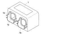
図1は組立状態の斜視図、図2は分解斜視図、図3は筐体の斜視図である。合成樹脂又は金属製の筐体1の側面に設けた孔部1aには、例えば3個の接続用コネクタ2と1個の回路チェック用コネクタ3が防水シール部材4を介して固定されている。また、筐体1の孔部1aの周囲には、後述する保護カバーを固定するための枠部1bが設けられており、筐体1は例えば底部に蓋を設けて開放できるようにされている。
The present invention will be described in detail based on the embodiments shown in the drawings.
1 is a perspective view of the assembled state, FIG. 2 is an exploded perspective view, and FIG. 3 is a perspective view of the housing. For example, three
コネクタ2はそれぞれ多数の図示しない例えば雄型接続端子を内蔵しており、図4に示すように筐体1内において、雄型接続端子に電線5が接続され、コネクタ2同士間或いは同一コネクタ2の雄型接続端子同士が電線5により短絡されている。チェック用コネクタ3は回路検査チェック用であり、コネクタ2と同様に雄型接続端子を内蔵しており、これらの雄型接続端子は各コネクタ2の回路検査に必要な雄型接続端子と電線5を介して接続されている。
Each
各コネクタ2には相手側コネクタ6が嵌合するようにされ、この相手側コネクタ6には電線7を接続した図示しない例えば雌型接続端子が内蔵され、コネクタ2、6同士の嵌合がなされると、それぞれに内蔵する接続端子同士が連結し、電気的な接続がなされるようになっている。
Each
図5はコネクタ2、6の嵌合状態の縦断面図であり、コネクタ2、6同士の間は、図示しない合成ゴム製のシール部材により合わせ目から水が浸入しないようにされ、更に各電線7ごとに相手側コネクタ6のハウジングとの間が図示しないシール部材により同様にシールされているため、相手側コネクタ6の外部からコネクタ2のハウジング内に水が浸入することはない。
FIG. 5 is a vertical cross-sectional view of the
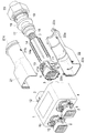
なお、実施例では電線7の本数が多く、コネクタ2、6同士の嵌合、解除に大きな力を必要とするため、例えばコネクタ2の側面にはピン8が設けられ、相手側コネクタ6にはカム溝9を有し軸10を中心に回動する回動レバー11が設けられ、カム溝9にピン8を係止して、回動レバー11の回動による両者のてこ作用によってコネクタ2、6同士を大きな力を要せずに嵌合、解離するようにしている。なお、回動レバー11の先端には、コネクタ2に設けた固定錠止部12に嵌合する錠止部13が設けられている。
In the embodiment, since the number of the
相手側コネクタ6の後方には、外面に補強用リブ14aを設けた合成樹脂製又は金属製の筒状プロテクタ14が連結され、この筒状プロテクタ14の相手側コネクタ6側の端部は、相手側コネクタ6の後部を覆うと共に嵌合する形状に形成され、相手側コネクタ6との間に合成ゴム製のシール部材15が介在されており、相手側コネクタ6と筒状プロテクタ14の間からの水の浸入が阻止されている。
A synthetic resin or metal
相手側コネクタ6に連結された筒状プロテクタ14と電線7を束ねた絶縁被覆16間には、筒状プロテクタ14の後方から、合成ゴムから成り筒状で内外面に断面波型を形成したフランジ付きのグロメット17が挿入され、筒状プロテクタ14内に水が浸入しない防水構造とされている。また、グロメット17の後方の絶縁被覆16上には、合成ゴム製の略円筒形で後部にテーパ面を有するブッシュング18、ブッシュング18のテーパ面に適合する環状形状の金属製スリーブ19、金属製又は合成樹脂製のナット20が挿着されている。
Between the
更に、相手側コネクタ6、筒状プロテクタ14の外側に、合成樹脂製又は金属製の2つ割りの保護筒21、22が被着され、これらの保護筒21、22には互いに係止する係止部21a、21b、22a、22bが設けられており、連結時には係止部21a、21b、22a、22bにより相互に係止される。保護筒21、22の前端部は、筐体1に設けた枠部1bに嵌め込まれて筐体1に固定され、後端部に設けたねじ部21c、22cにはブッシュング18、スリーブ19を介してナット20が螺合されている。
Further, synthetic resin or metal split
組立時には、電線7に接続端子を接続してから、接続端子を相手側コネクタ6内に挿着する。続いて、筒状プロテクタ14を相手側コネクタ6側に引き寄せ、筒状プロテクタ14を相手側コネクタ6に連結してから、絶縁被覆16と筒状プロテクタ14の後部の隙間にグロメット17を押し込み、筒状プロテクタ14の内部を防水構造とする。
At the time of assembly, after connecting the connection terminal to the
このようにして、予め組立てた相手側コネクタ6の組立体を、コネクタ2に回動レバー11を用いてコネクタ2に引き寄せて嵌合し、回動レバー11の錠止部13をコネクタ2の固定錠止部12に錠止し、コネクタ2、6が不時に外れないようにする。
In this way, the assembly of the
更に、ブッシュング18を筒状プロテクタ14の端部に突き当て、スリーブ19をブッシュング18のテーパ面に当接する。続いて、2つ割りの保護筒21、22を相手側コネクタ6、筒状プロテクタ14の周囲に上下方向から被着し、前端部を筐体1の枠部1aに固定し、保護筒21、22を係止部21a、21b、22a、22bを用いて一体に合体し、後端部のねじ部21c、22cにナット20を螺合して締め付ける。このナット20の締め付けにより、スリーブ19はブッシュング18のテーパ面に当接し、ブッシュング18を前方に押し込むことにより、絶縁被覆16と保護筒21、22とが強固に連結される。
Further, the
これにより、保護筒21、22によりコネクタ2、6に対する機械的な保護がなされると共に、絶縁被覆16に捩れや伸縮が加わっても、これらの力の一部はブッシュング18を介して保護筒21、22が受け、内部のコネクタ6に応力が加わることが少なくなる。
Thus, the
本実施例によれば、筐体1へのコネクタ2、3を固定、電線5による内部配線、更には相手側コネクタ6の組立を工場において行い、作業現場においては、コネクタ2に相手側コネクタ6を嵌合することにより、防水を伴う多数の配線の分岐、接続が容易に達成できる。
According to the present embodiment, the
なお、上述の説明では1個の相手側コネクタ6について述べたが、他の2つのコネクタ2の少なくとも1つについて、同様に相手側コネクタ6が嵌合される。また回路検査チェック用コネクタ3には、必要に応じて検査用回路を接続した相手側の回路検査チェック用コネクタを接続し、検査が必要な回線の回路検査を行うことができる。
In the above description, one
1 筐体
2、3、6 コネクタ
5、7 電線
14 筒状プロテクタ
16 絶縁被覆
17 グロメット
18 ブッシュング
20 ナット
21、22 保護筒
DESCRIPTION OF
Claims (4)
Priority Applications (1)
| Application Number | Priority Date | Filing Date | Title |
|---|---|---|---|
| JP2005378655A JP2007179931A (en) | 2005-12-28 | 2005-12-28 | Joint box |
Applications Claiming Priority (1)
| Application Number | Priority Date | Filing Date | Title |
|---|---|---|---|
| JP2005378655A JP2007179931A (en) | 2005-12-28 | 2005-12-28 | Joint box |
Publications (2)
| Publication Number | Publication Date |
|---|---|
| JP2007179931A true JP2007179931A (en) | 2007-07-12 |
| JP2007179931A5 JP2007179931A5 (en) | 2010-04-08 |
Family
ID=38304895
Family Applications (1)
| Application Number | Title | Priority Date | Filing Date |
|---|---|---|---|
| JP2005378655A Pending JP2007179931A (en) | 2005-12-28 | 2005-12-28 | Joint box |
Country Status (1)
| Country | Link |
|---|---|
| JP (1) | JP2007179931A (en) |
Cited By (5)
| Publication number | Priority date | Publication date | Assignee | Title |
|---|---|---|---|---|
| JP2010170946A (en) * | 2009-01-26 | 2010-08-05 | Smk Corp | Branching connector |
| JP2014095387A (en) * | 2014-01-07 | 2014-05-22 | Yanmar Co Ltd | Engine |
| JP2015022883A (en) * | 2013-07-18 | 2015-02-02 | 株式会社デンソー | Connector, and electronic device employing the same |
| KR101533802B1 (en) * | 2013-12-27 | 2015-07-06 | 주식회사 유라코퍼레이션 | Box for supporting connectors used in vehicle |
| WO2020095669A1 (en) * | 2018-11-09 | 2020-05-14 | 株式会社デンソー | Protective cover and vehicle-mounted device |
Citations (5)
| Publication number | Priority date | Publication date | Assignee | Title |
|---|---|---|---|---|
| JPS59185675U (en) * | 1983-05-30 | 1984-12-10 | 株式会社東芝 | check connector |
| JPH0553160U (en) * | 1991-12-20 | 1993-07-13 | 第一電子工業株式会社 | connector |
| JPH09293557A (en) * | 1996-04-26 | 1997-11-11 | Sumitomo Wiring Syst Ltd | Protection cover for wire body connecting component |
| JPH1167329A (en) * | 1997-08-19 | 1999-03-09 | Sumitomo Wiring Syst Ltd | Waterproof connector |
| JP2004158234A (en) * | 2002-11-05 | 2004-06-03 | Yazaki Corp | Joint connector |
-
2005
- 2005-12-28 JP JP2005378655A patent/JP2007179931A/en active Pending
Patent Citations (5)
| Publication number | Priority date | Publication date | Assignee | Title |
|---|---|---|---|---|
| JPS59185675U (en) * | 1983-05-30 | 1984-12-10 | 株式会社東芝 | check connector |
| JPH0553160U (en) * | 1991-12-20 | 1993-07-13 | 第一電子工業株式会社 | connector |
| JPH09293557A (en) * | 1996-04-26 | 1997-11-11 | Sumitomo Wiring Syst Ltd | Protection cover for wire body connecting component |
| JPH1167329A (en) * | 1997-08-19 | 1999-03-09 | Sumitomo Wiring Syst Ltd | Waterproof connector |
| JP2004158234A (en) * | 2002-11-05 | 2004-06-03 | Yazaki Corp | Joint connector |
Cited By (10)
| Publication number | Priority date | Publication date | Assignee | Title |
|---|---|---|---|---|
| JP2010170946A (en) * | 2009-01-26 | 2010-08-05 | Smk Corp | Branching connector |
| JP4730794B2 (en) * | 2009-01-26 | 2011-07-20 | Smk株式会社 | Branch connector |
| JP2015022883A (en) * | 2013-07-18 | 2015-02-02 | 株式会社デンソー | Connector, and electronic device employing the same |
| KR101533802B1 (en) * | 2013-12-27 | 2015-07-06 | 주식회사 유라코퍼레이션 | Box for supporting connectors used in vehicle |
| JP2014095387A (en) * | 2014-01-07 | 2014-05-22 | Yanmar Co Ltd | Engine |
| WO2020095669A1 (en) * | 2018-11-09 | 2020-05-14 | 株式会社デンソー | Protective cover and vehicle-mounted device |
| JP2020077586A (en) * | 2018-11-09 | 2020-05-21 | 株式会社デンソー | Protective cover and in-vehicle device |
| CN113169478A (en) * | 2018-11-09 | 2021-07-23 | 株式会社电装 | Protective cover and vehicle-mounted device |
| JP7159798B2 (en) | 2018-11-09 | 2022-10-25 | 株式会社デンソー | Protective covers and on-board equipment |
| US11923635B2 (en) | 2018-11-09 | 2024-03-05 | Denso Corporation | Protective cover and on-vehicle device |
Similar Documents
| Publication | Publication Date | Title |
|---|---|---|
| EP2456018B1 (en) | Waterproof structure | |
| JP6610954B2 (en) | Shield connector | |
| CN108075249B (en) | Protection member and wire harness | |
| JP6157732B2 (en) | Plug connector | |
| JP2004288544A (en) | Wire connection structure to shield case of instrument | |
| JP2004039332A (en) | Connector for tractor, and manufacturing method therefor | |
| WO2018168394A1 (en) | Waterproof structure for connector | |
| JP2007179931A (en) | Joint box | |
| JP2006031962A (en) | Connector for apparatus | |
| TWI645630B (en) | Connectors for connecting cables | |
| JP5501140B2 (en) | Shield connector | |
| JP5170013B2 (en) | Shield connector | |
| JP2011086509A (en) | Connector device | |
| JP2002324616A (en) | Shield connector device for equipment | |
| JPH07326422A (en) | Waterproof connector and waterproof connector assembly | |
| JP2005347012A (en) | Assembly structure of panel penetration connector | |
| JP4278556B2 (en) | Connector mating structure | |
| JP2009295550A (en) | Packing, and structure for fitting packing | |
| JP4065164B2 (en) | Waterproof structure for electrical connectors | |
| JP4238185B2 (en) | Waterproof connector | |
| CN109273917A (en) | With plastic shell water-proof connector female and with plastic shell water-proof connector | |
| CN214378997U (en) | Lock catch type connector shell assembly with flexible installation, connector and electrical equipment | |
| CN209104465U (en) | With plastic shell water-proof connector female and with plastic shell water-proof connector | |
| KR101429669B1 (en) | Assembly Connector | |
| CN220585641U (en) | Cable harness |
Legal Events
| Date | Code | Title | Description |
|---|---|---|---|
| A621 | Written request for application examination |
Effective date: 20080930 Free format text: JAPANESE INTERMEDIATE CODE: A621 |
|
| A521 | Written amendment |
Effective date: 20100219 Free format text: JAPANESE INTERMEDIATE CODE: A523 |
|
| A977 | Report on retrieval |
Effective date: 20101012 Free format text: JAPANESE INTERMEDIATE CODE: A971007 |
|
| A131 | Notification of reasons for refusal |
Free format text: JAPANESE INTERMEDIATE CODE: A131 Effective date: 20101019 |
|
| A02 | Decision of refusal |
Effective date: 20110301 Free format text: JAPANESE INTERMEDIATE CODE: A02 |