JP2007176307A - Colliding position detecting device of vehicle - Google Patents
Colliding position detecting device of vehicle Download PDFInfo
- Publication number
- JP2007176307A JP2007176307A JP2005376902A JP2005376902A JP2007176307A JP 2007176307 A JP2007176307 A JP 2007176307A JP 2005376902 A JP2005376902 A JP 2005376902A JP 2005376902 A JP2005376902 A JP 2005376902A JP 2007176307 A JP2007176307 A JP 2007176307A
- Authority
- JP
- Japan
- Prior art keywords
- collision
- vehicle
- impact force
- input position
- impact
- Prior art date
- Legal status (The legal status is an assumption and is not a legal conclusion. Google has not performed a legal analysis and makes no representation as to the accuracy of the status listed.)
- Pending
Links
Images


Abstract
Description
本発明は、衝突時、自車に対する衝撃力の入力位置を検出する車両の衝突位置検出装置の技術分野に属する。 The present invention belongs to a technical field of a vehicle collision position detection device that detects an input position of an impact force to a host vehicle at the time of a collision.
従来、車両の前後方向の減速度を検出するXGセンサと、車両の左右方向の減速度を検出するYGセンサと、を備え、衝突時、XGセンサからの出力信号を時間について積分し、前後方向の減速度ベクトルを演算し、また、YGセンサからの出力信号を時間について積分し、左右方向の減速度ベクトルを演算し、前後方向の減速度ベクトルと左右方向の減速度ベクトルとの合力ベクトルを求め、衝突の大きさと方向を特定するものが知られている(例えば、特許文献1参照。)。
しかしながら、従来の車両の衝突方向検出装置にあっては、XGセンサとYGセンサからの出力信号を時間について積分演算処理を必要とするものであるため、演算量が多く、演算時間が長くなってしまい、演算時間を短時間に設定すれば衝突方向の検出精度が低くなるし、演算時間を長時間に設定すれば衝突方向を特定するまでに時間がかかってしまい、衝突方向情報に基づいて作動するエアバック等の展開タイミングが遅れてしまう、という問題があった。 However, in the conventional vehicle collision direction detection device, since the output signals from the XG sensor and the YG sensor require integral calculation processing with respect to time, the calculation amount is large and the calculation time becomes long. Therefore, if the calculation time is set to a short time, the detection accuracy of the collision direction is lowered, and if the calculation time is set to a long time, it takes time until the collision direction is specified, and the operation is performed based on the collision direction information. There was a problem that the deployment timing of the airbag to be delayed was delayed.
本発明は、上記問題に着目してなされたもので、衝突時、自車に対する衝撃力の入力位置を、応答良く、かつ、精度良く検出することができる車両の衝突位置検出装置を提供することを目的とする。 The present invention has been made paying attention to the above problem, and provides a vehicle collision position detection device capable of detecting the input position of impact force to the own vehicle in a responsive and accurate manner at the time of a collision. With the goal.
上記目的を達成するため、本発明では、衝突時、自車に対する衝撃力の入力位置を検出する車両の衝突位置検出装置であって、
自車への衝撃力を検出して信号を出力する少なくとも3個の衝突センサを備え、
前記少なくとも3個の衝突センサは、車両全周の衝撃入力位置を、選択した2個の衝突センサと等距離にある車両周上位置を境として複数の領域に分けたとき、各領域で異なる検出順序となる車両位置に配置し、
In order to achieve the above object, in the present invention, a collision position detection device for a vehicle that detects an input position of an impact force to the vehicle at the time of a collision,
It has at least three collision sensors that detect the impact force on the vehicle and output a signal,
The at least three collision sensors are detected differently in each region when the impact input position of the entire circumference of the vehicle is divided into a plurality of regions with the vehicle circumferential position at the same distance as the two selected collision sensors as a boundary. Placed in the vehicle position in order,
衝突時、前記少なくとも3個の衝突センサからの衝撃力の検出順序により自車への衝撃力の入力位置を特定する衝撃入力位置特定手段を設けたことを特徴とする。 In the event of a collision, there is provided an impact input position specifying means for specifying an input position of the impact force to the host vehicle based on the detection order of the impact force from the at least three collision sensors.
よって、本発明の車両の衝突位置検出装置にあっては、少なくとも3個の衝突センサが、車両全周の衝撃入力位置を、選択した2個の衝突センサと等距離にある車両周上位置を境として複数の領域に分けたとき、各領域で異なる検出順序となる車両位置に配置される。そして、衝突時、衝撃入力位置特定手段において、少なくとも3個の衝突センサからの衝撃力の検出順序により自車への衝撃力の入力位置が特定される。
すなわち、自車への衝撃力の入力位置を特定するにあたって、衝突センサからの衝撃力の検出順序を用いた判別処理によるものであるため、積分演算等による演算処理時間を要さず、例えば、3個の衝突センサを配置した場合、2個目の衝突センサによる衝撃力の検出開始時点で3個の衝撃センサの検出順序が決定され、入力位置を特定することが可能である。したがって、衝突時、自車に対する衝撃力の入力位置が応答良く検出される。
例えば、前後方向の減速度ベクトルと左右方向の減速度ベクトルとの合力ベクトルにより衝突方向を検出する場合、2つのベクトルが確定するまでは検出される衝突方向がふらつき、応答良く衝突方向を検出しようとすると、衝突方向の検出精度が低くなる。
これに対し、本発明では、自車への衝撃力の入力位置を特定するにあたって、衝突センサからの衝撃力の検出順序により衝撃力の入力位置を特定するため、検出順序が確定した時点で衝撃力の入力位置を分けられた1つ領域に特定することができる。したがって、衝突時、自車に対する衝撃力の入力位置が精度良く検出される。
この結果、衝突時、自車に対する衝撃力の入力位置を、応答良く、かつ、精度良く検出することができる。
Therefore, in the vehicle collision position detection device of the present invention, at least three collision sensors have the vehicle circumferential position at the same distance as the two selected collision sensors. When divided into a plurality of areas as boundaries, they are arranged at vehicle positions having different detection orders in each area. In the event of a collision, the impact input position specifying means specifies the input position of the impact force to the host vehicle based on the detection order of the impact force from at least three collision sensors.
That is, in identifying the input position of the impact force to the host vehicle, because it is based on a discrimination process using the detection order of the impact force from the collision sensor, it does not require calculation processing time such as integral calculation, for example, When three collision sensors are arranged, the detection order of the three impact sensors is determined at the start of detection of the impact force by the second collision sensor, and the input position can be specified. Therefore, at the time of collision, the input position of the impact force with respect to the own vehicle is detected with good response.
For example, when the collision direction is detected by the resultant vector of the deceleration vector in the front-rear direction and the deceleration vector in the left-right direction, the detected collision direction will fluctuate until the two vectors are determined, and the collision direction will be detected with good response. Then, the detection accuracy of the collision direction is lowered.
On the other hand, in the present invention, when the input position of the impact force to the host vehicle is specified, the input position of the impact force is specified by the detection order of the impact force from the collision sensor. The input position of the force can be specified as one divided area. Therefore, at the time of collision, the input position of the impact force with respect to the own vehicle is detected with high accuracy.
As a result, it is possible to detect the input position of the impact force with respect to the host vehicle with good response and accuracy at the time of collision.
以下、本発明の車両の衝突位置検出装置を実施するための最良の形態を、図面に示す実施例1に基づいて説明する。 Hereinafter, the best mode for carrying out a collision position detecting apparatus for a vehicle according to the present invention will be described based on Example 1 shown in the drawings.
まず、構成を説明する。
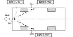
図1は実施例1の衝突位置検出装置が適用されたハイブリッド車両(車両の一例)を示す全体システム図、図2は実施例1の衝突位置検出装置における3個の衝突センサの車両への設定位置を示す配置レイアウト図である。
First, the configuration will be described.
FIG. 1 is an overall system diagram showing a hybrid vehicle (an example of a vehicle) to which the collision position detection device of the first embodiment is applied. FIG. 2 is a diagram illustrating the setting of three collision sensors in the collision position detection device of the first embodiment. It is the arrangement layout figure which shows a position.
実施例1のハイブリッド車両は、図1に示すように、CPU101と、補助バッテリ102と、ブレーキアクチュエータ201と、機械ブレーキ202と、強電バッテリ301と、インバータ302と、モータ303と、発電機304と、エンジン305と、動力分割機構306と、アクセルセンサ401と、ブレーキセンサ402と、DC/DCコンバータ403と、前方衝突センサ501(第1衝突センサ)と、右側方衝突センサ502(第2衝突センサ)と、左側方衝突センサ503(第3衝突センサ)と、ヨーレートセンサ504(車両挙動検出手段)と、乗員保護装置505と、GPS601と、外部発信器602と、を備えている。
As shown in FIG. 1, the hybrid vehicle according to the first embodiment includes a
前記CPU101は、強電バッテリ301をモニタし、SOCや温度や劣化状態に応じて入出力可能電力量を算出し、これを基にインバータ302を制御することにより、モータ303(フロント駆動用)と発電機304を動作させると共に、エンジン305を制御する(モータ−エンジン間の駆動力配分含む)。
また、CPU101は、モータ303による回生制動力を考慮し、機械ブレーキ202により発生する制動力演算指令値(前後制動力配分を含む)をブレーキアクチュエータ201へと送信する。
前記前方衝突センサ501と、前記右側方衝突センサ502と、前記左側方衝突センサ503の検出順序を確認し、2つのセンサ間の検出タイミングのずれ量(位相差)の大小を比較することにより、衝突時、衝撃力の車体入力位置を特定する。
上記衝撃力の入力位置情報に、GPS601により検出した事故箇所を加え、外部発信器602により、消防署などのレスキュー部隊へ情報を送信する。
なお、自車速度は、モータ303の回転数により把握することを基本とする。
The
Further, the
By confirming the detection order of the
The accident location detected by the
The vehicle speed is basically determined based on the number of rotations of the
前記補助バッテリ102は、CPU101の動作電源を提供する役目を有する。本システムでは、強電バッテリ301を電源としたDC/DCコンバータ403により電力を供給することとする。
The
前記ブレーキアクチュエータ201は、CPU101により演算された機械ブレーキ202で発生させるべき摩擦制動力演算指令値を受信し、それに応じ、機械ブレーキ202に対し必要な油圧をかける。
The brake actuator 201 receives a friction braking force calculation command value to be generated by the
前記機械ブレーキ202は、ブレーキアクチュエータ201により発生された油圧に応じ、制動力を発生させる。
The
前記強電バッテリ301は、モータ303に対し、インバータ302を経由して電力を供給することで車両走行をアシストすると共に、モータ303及び発電機304が発電した電力をインバータ302を経由して回収する役目を有する。
The high-
前記インバータ302は、CPU101により直接制御されている。エンジン305の発生トルク及び回転数に応じて強電バッテリ301の電気エネルギーをモータ303へ供給すること、及び発電機304を動作させて発生した電気エネルギーを強電バッテリ301へと戻す役目を有する。なお、モータ303と発電機304とエンジン305は、遊星歯車機構(動力分割機構306に内蔵)に直結しているため、トルク及び回転数のバランスを保つように制御しないと車両を正常に作動させることができない。
The
前記モータ303は、車速が低い場合は単独で駆動トルクを発生させる。また、車速が高い場合は、エンジン305の駆動トルクをアシストしている。さらに、減速時は発電作用(回生制動)することにより電気エネルギーを発生させ、これをインバータ302を経由して強電バッテリ301へ戻す役目を有する。
The
前記発電機304は、ハイブリッド電気自動車は基本的にスタータを持たない。本システムを適用した車両始動時は、強電バッテリ301から電力を供給し、モータとして動作することでエンジン305の始動をサポートする。通常走行時は、モータ303とエンジン305とをバランスさせることで電気エネルギーを発生(発電)し、これを強電バッテリ301へ戻す。時には直接、モータ303へ供給することにより、急激な加速に対応することも可能である。
The
前記エンジン305は、CPU101により直接制御されている。具体的には、車速が高い場合、車両駆動のためにトルクを発生させている(車速が低い場合はモータ走行となるため、制御不要:強いて挙げれば起動させない制御を適用している)。
The
前記動力分割機構306は、遊星歯車機構を有し、キャリアにはエンジン305、リングギヤにはモータ303、サンギヤには発電機304が直接接続している。従来システムのトランスミッション相当も内部に構成されている。
The
前記アクセルセンサ401は、ドライバーが加速時に踏み込んだアクセルペダルストローク量をCPU101へ送信する。
The accelerator sensor 401 transmits to the
前記ブレーキセンサ402は、ドライバーが減速時時に踏み込んだブレーキペダルストローク量をCPU101へ送信する。
The brake sensor 402 transmits to the
前記DC/DCコンバータ403は、強電バッテリ301からのエネルギーを12Vへと変換し、補助バッテリ102へと供給する。すなわち、従来のエンジン車両におけるオルタネータと同様の機能を有する。
The DC /
前記前方衝突センサ501と右側方衝突センサ502と左側方衝突センサ503は、図2に示すように、車両全周の衝撃入力位置を、選択した2個の衝突センサと等距離にある車両周上位置を境として複数の領域に分けたとき、各領域で異なる検出順序となる車両位置に配置している(図4参照)。
前記前方衝突センサ501は、車両フロントの中央位置に配置し、主に前方からの衝撃を検出するために使用される。
前記右側方衝突センサ502は、車両中央部の右側位置に配置し、主に右側方からの衝撃を検出するために使用される。
前記左側方衝突センサ503は、車両中央部の左側位置に配置し、主に左側方からの衝撃を検出するために使用される。
これらの衝突センサ501,502,503としては、加減速を検出するような精度の高いGセンサを要さないことで、例えば、エアバックシステムで用いられる作動スイッチのような、自車への所定値以上の衝撃力の入力に対しパルス信号を出力するオン/オフスイッチが用いられる。
As shown in FIG. 2, the
The
The right
The left
These
前記ヨーレートセンサ504は、前記前方衝突センサ501と右側方衝突センサ502と左側方衝突センサ503により検出された衝突信号と、事故によるヨーモーメント発生状況を照合し、情報の精度を高めるために活用される。また、検出値により衝突後の車両挙動に付いても把握し、外部レスキュー部隊へと情報展開できるようにする。
The yaw rate sensor 504 is utilized to increase the accuracy of information by collating the collision signals detected by the
前記乗員保護装置505は、エアバック、プリクラッシュシートベルトなど、衝突時に乗員への衝撃を低減させるアイテムの全てを示す。
実施例1では、乗員保護装置505として、運転席エアバックAと、助手席エアバックBと、右サイドエアバックCと、左サイドエアバックDが搭載されている(図8(b)を参照)。
The occupant protection device 505 indicates all items such as an air bag and a pre-crash seat belt that reduce the impact on the occupant during a collision.
In the first embodiment, the driver's seat airbag A, the passenger seat airbag B, the right side airbag C, and the left side airbag D are mounted as the occupant protection device 505 (see FIG. 8B). ).
前記GPS601(Global Positioning System)は、実施例1のシステムにおいて、事故現場を特定する際に活用する。 The GPS 601 (Global Positioning System) is used when specifying the accident site in the system of the first embodiment.
前記外部発信器602は、事故現場、事故状態(衝突方法、検出ダイアグ)などをまとめ、消防署などのレスキュー部隊へと情報送信し、レスキュー作業の効率化を図る。 The external transmitter 602 summarizes the accident site, the accident state (collision method, detection diagnosis), etc., and transmits information to a rescue unit such as a fire department to improve the efficiency of the rescue operation.
図3は実施例1のCPU101にて実行される衝撃入力位置特定処理、エアバック作動制御処理、事故情報発信処理の流れを示すフローチャートであり、以下、各ステップについて説明する。
FIG. 3 is a flowchart showing the flow of the impact input position specifying process, the airbag operation control process, and the accident information transmission process executed by the
ステップS1では、前方衝突センサ501と右側方衝突センサ502と左側方衝突センサ503の何れかにより衝突センサ信号を受信したか否かを判断し、Yesの場合はステップS2へ移行し、Noの場合はステップS1の判断を繰り返す。
In step S1, it is determined whether or not a collision sensor signal is received by any one of the
ステップS2では、ステップS1での衝突センサ信号の受信という判断に続き、2つ目のセンサ信号を入力した時点で3個の前方衝突センサ501と右側方衝突センサ502と左側方衝突センサ503からの衝撃力の検出順序を確認し、確認した検出順序により自車への衝撃力の入力位置(領域にてあらわされる)を特定し、ステップS3へ移行する(衝撃入力位置特定手段)。
ここで、センサ検出順序による入力位置は、図4に示すように、前方衝突センサ501を(1)、右側方衝突センサ502を(2)、左側方衝突センサ503を(3)であらわしたとき、下記のように特定される。
まず、車両全周の衝撃入力位置を、選択した2個の衝突センサ(2),(3)と等距離にある車両周上位置P1,P2と、選択した2個の衝突センサ(1),(2)と等距離にある車両周上位置P3,P4と、選択した2個の衝突センサ(1),(3)と等距離にある車両周上位置P5,P6と、を境として6つの領域に分ける。
このとき、P1〜P3の右前方領域FRでは、(1)→(2)→(3)の検出順序となり、P1〜P4の左前方領域FLでは、(1)→(3)→(2)の検出順序となる。
P3〜P5の右側方領域SRでは、(2)→(1)→(3)の検出順序となり、P2〜P5の右後方領域RRでは、(2)→(3)→(1)の検出順序となる。
P4〜P6の左側方領域SLでは、(3)→(1)→(2)の検出順序となり、P2〜P6の左後方領域RLでは、(3)→(2)→(1)の検出順序となる。
そして、車両周上位置P1では、(1)→(2),(3)の検出順序となり、車両周上位置P2では、(2),(3)→(1)の検出順序となり、車両周上位置P3では、(1),(2)→(3)の検出順序となり、車両周上位置P4では、(1),(3)→(2)の検出順序となり、車両周上位置P5では、(2)→(1),(3)の検出順序となり、車両周上位置P6では、(3)→(1),(2)の検出順序となる。
In step S2, following the determination of reception of the collision sensor signal in step S1, when the second sensor signal is input, the signals from the three
Here, as shown in FIG. 4, the input position according to the sensor detection order is represented by (1) for the
First, the impact input position of the entire circumference of the vehicle is determined by setting the vehicle circumference positions P1, P2 that are equidistant from the selected two collision sensors (2), (3), and the two selected collision sensors (1), The vehicle circumference positions P3 and P4 that are equidistant from (2) and the two selected collision sensors (1) and (3) and the vehicle circumference positions P5 and P6 that are equidistant are the six boundaries. Divide into areas.
At this time, in the right front area FR of P1 to P3, the detection order is (1) → (2) → (3), and in the left front area FL of P1 to P4, (1) → (3) → (2) This is the detection order.
In the right side area SR of P3 to P5, the detection order is (2) → (1) → (3), and in the right rear area RR of P2 to P5, the detection order is (2) → (3) → (1). It becomes.
In the left area SL of P4 to P6, the detection order is (3) → (1) → (2), and in the left rear area RL of P2 to P6, the detection order is (3) → (2) → (1). It becomes.
At the vehicle circumferential position P1, the detection order is (1) → (2), (3), and at the vehicle circumferential position P2, the detection order is (2), (3) → (1). At the upper position P3, the detection order is (1), (2) → (3), at the vehicle circumferential position P4, the detection order is (1), (3) → (2), and at the vehicle circumferential position P5. The detection order is (2) → (1), (3). At the vehicle circumferential position P6, the detection order is (3) → (1), (2).
ステップS3では、ステップS2での検出順序確認に続き、3つ目のセンサ信号を入力した時点でステップS2で決めた入力存在領域にてセンサ間の検出タイミングのずれ量である位相差により自車への衝撃力の入力位置を特定し、ステップS4へ移行する(衝撃入力位置特定手段)。
ここで、検出順序による領域特定(6領域)をさらに細分化して特定(12領域)するのが位相差による入力位置の特定であり、図5〜図7に示す入力位置特定マップにより、図8に示す領域I〜IXのいずれかが特定される。
すなわち、衝突センサ(1)がはじめに検出した場合、図5に示すように、P1〜P3の右前方領域FRでは、(2)→(3)の位相差の大小により、図8に示す領域Iと領域IIと領域IXとに特定される。P1〜P4の左前方領域FLでは、(3)→(2)の位相差の大小により、図8に示す領域Iと領域IIIと領域IVとに特定される。
衝突センサ(2)がはじめに検出した場合、図6に示すように、P3〜P5の右側方領域SRでは、(1)→(3)の位相差の大小により、図8に示す領域Iと領域IIと領域IXとに特定される。P2〜P5の右後方領域RRでは、(3)→(1)の位相差の大小により、図8に示す領域Iと領域VIIと領域VIIIとに特定される。
衝突センサ(3)がはじめに検出した場合、図7に示すように、P4〜P6の左側方領域SLでは、(1)→(2)の位相差の大小により、図8に示す領域Iと領域IIIと領域IVとに特定される。P2〜P6の左後方領域RLでは、(2)→(1)の位相差の大小により、図8に示す領域Iと領域VIと領域Vとに特定される。
In step S3, following the detection order confirmation in step S2, when the third sensor signal is input, the vehicle is detected based on the phase difference that is the detection timing shift amount between the sensors in the input presence area determined in step S2. The input position of the impact force is specified, and the process proceeds to step S4 (impact input position specifying means).
Here, the region specification (6 regions) based on the detection order is further subdivided and specified (12 regions) to specify the input position based on the phase difference. The input position specification map shown in FIGS. Any one of the areas I to IX shown in FIG.
That is, when the collision sensor (1) first detects, in the right front region FR of P1 to P3, as shown in FIG. 5, the region I shown in FIG. And region II and region IX. The left front region FL of P1 to P4 is specified as a region I, a region III, and a region IV shown in FIG. 8 depending on the size of the phase difference of (3) → (2).
When the collision sensor (2) first detects, in the right side region SR of P3 to P5, as shown in FIG. 6, the region I and region shown in FIG. Specified as II and Region IX. The right rear region RR of P2 to P5 is specified as a region I, a region VII, and a region VIII shown in FIG. 8 depending on the phase difference from (3) to (1).
When the collision sensor (3) first detects, in the left side region SL of P4 to P6, as shown in FIG. 7, the region I and region shown in FIG. Specified as III and Region IV. The left rear region RL from P2 to P6 is specified as a region I, a region VI, and a region V shown in FIG. 8 depending on the phase difference from (2) to (1).
ステップS4では、ステップS3での入力位置の特定に続き、特定された入力位置に応じて乗員保護装置505である運転席エアバックAと、助手席エアバックBと、右サイドエアバックCと、左サイドエアバックDの作動タイミングを決定し、ステップS5へ移行する。
ここで、エアバックA,B,C,Dの作動タイミングは、図8に示す各領域毎に下記のように決定される。
領域I :A=B=C=D
領域II :A⇒B⇒D⇒C
領域III :B⇒A⇒C⇒D
領域IV :D⇒C⇒A=B
領域V :D⇒C⇒A=B(=領域IV)
領域VI :A=B⇒C=D
領域VII :A=B⇒C=D(=領域VI)
領域VIII:C⇒D⇒A=B
領域IX :C⇒D⇒A=B(=領域VIII)
すなわち、車両のコーナー側へのオフセット衝突の場合は、エアバックを同時展開とするが、基本的に、特定された入力位置に近い位置のエアバックの展開を優先する展開順序により作動タイミングが設定される。
In step S4, following the specification of the input position in step S3, the driver's seat airbag A, the passenger seat airbag B, the right side airbag C, which is the occupant protection device 505, according to the specified input position, The operation timing of the left side airbag D is determined, and the process proceeds to step S5.
Here, the operation timing of the airbags A, B, C, and D is determined as follows for each region shown in FIG.
Region I: A = B = C = D
Area II: A⇒B⇒D⇒C
Area III: B⇒A⇒C⇒D
Area IV: D⇒C⇒A = B
Region V: D⇒C⇒A = B (= region IV)
Area VI: A = B⇒C = D
Area VII: A = B => C = D (= area VI)
Area VIII: C⇒D⇒A = B
Area IX: C⇒D⇒A = B (= area VIII)
In other words, in the case of an offset collision to the corner of the vehicle, the airbag is deployed at the same time, but basically the operation timing is set according to the deployment order that prioritizes the deployment of the airbag near the specified input position. Is done.
ステップS5では、ステップS4での乗員保護装置作動タイミングの決定に続き、決定されたタイミングにて4個のエアバックA,B,C,Dの作動を制御し、ステップS6へ移行する。なお、ステップS4及びステップS5は、乗員保護装置作動制御手段に相当する。 In step S5, following the determination of the occupant protection device operation timing in step S4, the operation of the four airbags A, B, C, and D is controlled at the determined timing, and the process proceeds to step S6. Steps S4 and S5 correspond to occupant protection device operation control means.
ステップS6では、ステップS5での乗員保護装置の作動に続き、モータ303の回転数を確認し、回転数がゼロ、つまり、車速がゼロ(=衝突が終了)となったか否かを判断し、Yesの場合はステップS7へ移行し、Noの場合はステップS6での判断を繰り返す。
In step S6, following the operation of the occupant protection device in step S5, the number of revolutions of the
ステップS7では、ステップS6での車速ゼロとの判断に続き、衝突開始時から衝突完了までのヨーレートセンサ504による車両挙動検出結果に基づき、衝撃力の大きさ(事故の程度)を把握し、ステップS8へ移行する。 In step S7, following the determination that the vehicle speed is zero in step S6, the magnitude of the impact force (degree of accident) is ascertained based on the vehicle behavior detection result by the yaw rate sensor 504 from the start of the collision to the completion of the collision. The process proceeds to S8.
ステップS8では、ステップS7での衝突後挙動確認に続き、GPS601からの情報と照合し、事故の発生場所及び事故後の車両が存在する場所を特定し、ステップS9へ移行する(事故位置特定手段)。なお、事故発生場所は、ログファイルの確認により特定することができる。
In step S8, after confirming the behavior after the collision in step S7, the information from the
ステップS9では、ステップS8での事故位置確認に続き、衝突程度を切り分けられるダイアグ確認方法(自己診断コードの確認方法)に基づき、自車システムのダイアグ発生状況を確認し、ステップS10へ移行する(ダイアグ確認手段)。 In step S9, following the accident position confirmation in step S8, based on a diagnostic confirmation method (a self-diagnosis code confirmation method) that can determine the degree of collision, the diagnostic status of the vehicle system is confirmed, and the process proceeds to step S10 ( Diag confirmation means).
ステップS10では、ステップS9でのダイアグ確認に続き、ダイアグ発生状況と事故位置を含む事故情報を整理し、外部発信器602を用いて外部レスキュー部隊へと発信し、終了へ移行する(事故情報発信手段)。 In step S10, following the diagnosis confirmation in step S9, the accident information including the diagnosis occurrence status and the accident position is organized, transmitted to the external rescue unit using the external transmitter 602, and the process proceeds to the end (accident information transmission). means).
次に、作用を説明する。
[背景技術]
衝突時の乗員の安全性を確保する観点から乗員保護装置として、複数のエアバックやプリクラッシュシートベルトなどが車両に採用されている。しかし、例えば、衝突方向がどの方向であるかにかかわらず衝突時に複数のエアバックを同時タイミングで作動させるようにした場合、衝突方向によってはエアバックの同時展開が必ずしも適切であるとは限らない。このように、複数のエアバックの展開順序を適切に規定するため、衝突方向の情報を得たいという要求がある。
Next, the operation will be described.
[Background technology]
A plurality of airbags, pre-crash seat belts, and the like are employed in the vehicle as an occupant protection device from the viewpoint of ensuring the safety of the occupant during a collision. However, for example, when a plurality of airbags are operated at the same time during a collision regardless of the collision direction, the simultaneous deployment of the airbags is not always appropriate depending on the collision direction. . As described above, there is a demand for obtaining information on the collision direction in order to appropriately define the order in which the plurality of airbags are deployed.
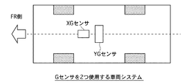
これに対し、特開平5−193439号公報には、図9に示すように、車両の前後方向の減速度を検出するXGセンサと、車両の左右方向の減速度を検出するYGセンサと、を備え、衝突時、XGセンサからの出力信号を時間について積分し、前後方向の減速度ベクトルを演算し、また、YGセンサからの出力信号を時間について積分し、左右方向の減速度ベクトルを演算し、前後方向の減速度ベクトルと左右方向の減速度ベクトルとの合力ベクトルを求め、衝突の大きさと方向を特定するものが記載されている。 In contrast, in Japanese Patent Laid-Open No. 5-193439, as shown in FIG. 9, an XG sensor that detects a deceleration in the front-rear direction of the vehicle and a YG sensor that detects a deceleration in the left-right direction of the vehicle are provided. In the event of a collision, the output signal from the XG sensor is integrated over time to calculate the longitudinal deceleration vector, and the output signal from the YG sensor is integrated over time to calculate the lateral deceleration vector. In this document, the resultant vector of the longitudinal deceleration vector and the lateral deceleration vector is obtained to specify the magnitude and direction of the collision.
しかしながら、上記衝突方向検出装置にあっては、XGセンサとYGセンサからの出力信号を時間について積分演算処理を必要とするものであるため、図10に示すように、衝突方向を特定するためのベクトル計算に長い時間を要し、衝突方向を特定するまでに時間がかかってしまう。 However, in the above collision direction detection device, since the output signals from the XG sensor and the YG sensor require integration calculation processing with respect to time, as shown in FIG. The vector calculation takes a long time, and it takes time to specify the collision direction.
このため、エアバックシステムに上記衝突方向検出装置を採用し、十分な演算処理時間を待って衝突方向を特定した場合、複数のエアバックの展開順序を規定すると、エアバックの展開タイミングが遅れてしまう。このため、例えば、図10に示すように、同時タイミングによるエアバックの展開作動にせざるを得ない。
また、演算処理時間を短くして応答良く衝突方向を特定すれば、衝突方向の検出精度が低くなり、衝突方向を確認できず、複数のエアバックの展開順序を適切に規定できない。
For this reason, when the collision direction detection device is employed in the airbag system and the collision direction is specified after waiting for a sufficient calculation processing time, if the deployment order of a plurality of airbags is defined, the deployment timing of the airbag is delayed. End up. For this reason, for example, as shown in FIG. 10, the airbag must be deployed at the same time.
Moreover, if the collision processing direction is shortened and the collision direction is identified with good response, the collision direction detection accuracy is lowered, the collision direction cannot be confirmed, and the deployment order of the plurality of airbags cannot be properly defined.
[衝突時の衝撃力の入力位置特定作用]
これに対し、実施例1の衝突位置検出装置では、少なくとも3個以上の衝突センサを適切に車両に配置し、積分演算処理などを用いず、位置検出手法として迅速なセンサ検出順序の判別処理を採用することで、衝突時、自車に対する衝撃力の入力位置を、応答良く、かつ、精度良く検出することができるようにした。
[Input position specifying action of impact force at the time of collision]
On the other hand, in the collision position detection apparatus according to the first embodiment, at least three or more collision sensors are appropriately arranged in the vehicle, and a rapid sensor detection order determination process is performed as a position detection method without using an integration calculation process or the like. By adopting it, it is possible to detect the input position of the impact force to the vehicle at the time of collision with good response and accuracy.
すなわち、衝突時には、図3のフローチャートにおいて、ステップS1→ステップS2→ステップS3へと進み、ステップS2では、ステップS1での衝突センサ信号の受信という判断に続き、2つ目のセンサ信号を入力した時点で3個の衝突センサ501,502,503からの衝撃力の検出順序を確認し、確認した検出順序により自車への衝撃力の入力位置を特定する。
例えば、図11に示すように、時刻t1にて前方衝突センサ501(1)を検出し、時刻t2にて右側方衝突センサ502(2)を検出し、時刻t3にて左側方衝突センサ503(3)を検出した場合、(1)→(2)→(3)の検出順序であるため、図4に示すように、自車への衝撃力の入力位置がP1〜P3の右前方領域FRであると特定される。
That is, at the time of collision, in the flowchart of FIG. 3, the process proceeds from step S1 to step S2 to step S3. In step S2, the second sensor signal is input following the determination of reception of the collision sensor signal in step S1. At the time, the detection order of the impact force from the three
For example, as shown in FIG. 11, the front collision sensor 501 (1) is detected at time t1, the right side collision sensor 502 (2) is detected at time t2, and the left side collision sensor 503 ( When 3) is detected, the detection order is (1) → (2) → (3). Therefore, as shown in FIG. 4, the input position of the impact force to the vehicle is the front right region FR of P1 to P3. Is identified.
そして、ステップS3では、ステップS2での検出順序確認に続き、3つ目のセンサ信号を入力した時点でステップS2で決めた入力存在領域にてセンサ間の検出タイミングのずれ量である位相差により自車への衝撃力の入力位置を特定する。
例えば、図11に示すように、P1〜P3の右前方領域FRで、かつ、衝突センサ(1)がはじめに検出した場合、図5に示すように、(2)→(3)の位相差Δtの大小により、図8に示す領域IIに特定される。
In step S3, following the detection order confirmation in step S2, the phase difference that is the amount of detection timing deviation between the sensors in the input presence area determined in step S2 when the third sensor signal is input. Specify the input position of the impact force to the vehicle.
For example, as shown in FIG. 11, when the collision sensor (1) first detects in the right front region FR of P1 to P3, the phase difference Δt of (2) → (3) as shown in FIG. Is specified in the region II shown in FIG.
このように、自車への衝撃力の入力位置を特定するにあたって、衝突センサ(1),(2),(3)からの衝撃力の検出順序を用いた判別処理によるものであるため、積分演算等による演算処理時間を要さず、実施例1のように、3個の衝突センサ(1),(2),(3)を配置した場合、2個目の衝突センサによる衝撃力の検出開始時点で3個の衝撃センサの検出順序が決定され、入力位置を特定することが可能である。したがって、衝突時、自車に対する衝撃力の入力位置が応答良く検出される。 In this way, when identifying the input position of the impact force to the vehicle, it is based on the discrimination process using the detection order of the impact force from the collision sensors (1), (2), (3). When 3 collision sensors (1), (2), and (3) are arranged as in the first embodiment without calculating processing time by calculation, etc., detection of impact force by the second collision sensor The detection order of the three impact sensors is determined at the start time, and the input position can be specified. Therefore, at the time of collision, the input position of the impact force with respect to the own vehicle is detected with good response.
例えば、従来技術のように、前後方向の減速度ベクトルと左右方向の減速度ベクトルとの合力ベクトルにより衝突方向を検出する場合、2つのベクトルが確定するまでは検出される衝突方向がふらつき、応答良く衝突方向を検出しようとすると、衝突方向の検出精度が低くなる。
これに対し、実施例1では、自車への衝撃力の入力位置を特定するにあたって、衝突センサ(1),(2),(3)からの衝撃力の検出順序により衝撃力の入力位置を特定するため、検出順序が確定した時点で衝撃力の入力位置を、分けられた6領域の中から1つの領域に特定することができる。
For example, when the collision direction is detected by the resultant vector of the longitudinal and lateral deceleration vectors as in the prior art, the detected collision direction fluctuates until the two vectors are determined, and the response If the collision direction is well detected, the detection accuracy of the collision direction is lowered.
On the other hand, in the first embodiment, when the input position of the impact force to the host vehicle is specified, the input position of the impact force is determined by the detection order of the impact force from the collision sensors (1), (2), (3). Therefore, when the detection order is determined, the impact force input position can be specified as one area from among the six divided areas.
さらに、実施例1では、自車への衝撃力の入力位置を特定するにあたって、衝突センサ(1),(2),(3)からの衝撃力の検出順序により衝撃入力位置の存在領域(6領域のうち1領域)を決め、かつ、決めた存在領域にて位相差により衝撃力の入力位置を特定(12領域のうち1領域)するというように、「入力位置の存在領域決定」と「存在領域内での入力位置の細分特定」という2段階絞りによる入力位置検出手法を採用したため、衝突時、自車に対する衝撃力の入力位置が高精度に検出される。 Furthermore, in the first embodiment, when the input position of the impact force to the host vehicle is specified, the impact input position existing region (6) is determined by the detection order of the impact force from the collision sensors (1), (2), (3). "Determine input position existing area" and "Determine input position existing area" and determine the input position of impact force by phase difference in the determined existing area (1 area out of 12 areas). Since an input position detection method using a two-stage aperture called “subdivision of input position within an existing area” is adopted, the input position of the impact force against the host vehicle is detected with high accuracy at the time of collision.
上記のように、実施例1では、衝突時、自車に対する衝撃力の入力位置を検出する車両の衝突位置検出装置であって、自車への衝撃力を検出して信号を出力する少なくとも3個の衝突センサ501,502,503を備え、前記少なくとも3個の衝突センサ501,502,503は、車両全周の衝撃入力位置を、選択した2個の衝突センサと等距離にある車両周上位置を境として複数の領域に分けたとき、各領域で異なる検出順序となる車両位置に配置し、衝突時、前記少なくとも3個の衝突センサ501,502,503からの衝撃力の検出順序により自車への衝撃力の入力位置を特定する衝撃入力位置特定手段(ステップS2)を設けた。
このため、衝突時、自車に対する衝撃力の入力位置を、応答良く、かつ、精度良く検出することができる。
As described above, the first embodiment is a vehicle collision position detection device that detects the input position of the impact force to the host vehicle at the time of a collision, and detects at least the impact force on the host vehicle and outputs a signal. Each of the
For this reason, at the time of a collision, the input position of the impact force to the own vehicle can be detected with good response and high accuracy.
実施例1の衝突位置検出装置において、前記衝撃入力位置特定手段(ステップS2,ステップS3)は、衝突時、前記少なくとも3個の衝突センサ501,502,503からの衝撃力の検出順序により自車への衝撃力の入力存在領域を決め、決めた入力存在領域にてセンサ間の検出タイミングのずれ量である位相差により自車への衝撃力の入力位置を特定する。
例えば、衝突センサの検出順序のみにより衝撃力の入力位置を特定する場合、3個の衝突センサ501,502,503を用いると、入力位置は6領域のいずれかという特定となり、粗い特定となる。
これに対し、位相差による衝撃力の入力位置の特定手法を加えることで、3個の衝突センサ501,502,503を用いると、入力位置は6領域から12領域に細分化された特定となり、高精度にて自車に対する衝撃力の入力位置を特定することができる。
In the collision position detection apparatus according to the first embodiment, the impact input position specifying means (steps S2 and S3) is configured so that the impact force applied to the own vehicle is detected according to the detection order of the impact force from the at least three
For example, when the impact force input position is specified only by the detection order of the collision sensors, when the three
On the other hand, by adding a method for specifying the input position of the impact force due to the phase difference, if the three
実施例1の衝突位置検出装置において、前記衝突センサとして、車両フロントの中央位置に配置した第1衝突センサ501と、車両中央部の右側位置に配置した第2衝突センサ502と、車両中央部の左側位置に配置した第3衝突センサ503と、を用いた。
これによって、図4に示すように、車両全周のうち、車両前半分を右前方領域FRと、左前方領域FLと、右側方領域SRと、右後方領域RRと、の4つの領域に分け、車両後半分を左側方領域SLと、左後方領域RLと、の2つの領域に分けることができる。
このように、最小数である3個の衝突センサ501,502,503を用いながら、車両前半分への衝突を重視した領域分けとなり、自車の前方部や左右側部への衝突時、運転席及び助手席乗員を主体として搭載される乗員保護装置505の作動順序を適切に決めることができる。
In the collision position detection apparatus according to the first embodiment, as the collision sensor, a
Thus, as shown in FIG. 4, the front half of the vehicle is divided into four regions, a right front region FR, a left front region FL, a right side region SR, and a right rear region RR. The rear half of the vehicle can be divided into two regions, a left side region SL and a left rear region RL.
In this way, while using the minimum number of three
実施例1の衝突位置検出装置において、前記第1衝突センサ501、第2衝突センサ502、第3衝突センサ503は、自車への所定値以上の衝撃力の入力に対しパルス信号を出力するオン/オフスイッチである。
例えば、衝突センサとして、従来技術のように、減速度を精度良く検出するようなGセンサを用いた場合、1個のセンサ単価が高価となり、システムのコストアップとなる。
これに対し、3個の衝突センサ501,502,503をオン/オフスイッチとしたことで、低コストのシステムにて、衝突時、応答良く、かつ、高精度に自車に対する衝撃力の入力位置情報を取得することができる。
In the collision position detection apparatus according to the first embodiment, the
For example, when a G sensor that accurately detects deceleration is used as a collision sensor, the unit price of one sensor is expensive, which increases the cost of the system.
On the other hand, the three
[エアバック作動制御作用]
自車に対する衝撃力の入力位置が特定されると、図3のフロートチャートにおいて、ステップS3からステップS4→ステップS5へと進む流れとなる。ステップS4では、特定された入力位置に応じて乗員保護装置505である運転席エアバックAと、助手席エアバックBと、右サイドエアバックCと、左サイドエアバックDの作動タイミングを決定し、ステップS5では、決定されたタイミングにて4個のエアバックA,B,C,Dの作動が制御される。
[Airbag operation control action]
When the input position of the impact force with respect to the own vehicle is specified, the flow proceeds from step S3 to step S4 to step S5 in the float chart of FIG. In step S4, the operation timing of the driver's seat airbag A, the passenger seat airbag B, the right side airbag C, and the left side airbag D, which are the occupant protection devices 505, is determined according to the specified input position. In step S5, the operation of the four airbags A, B, C, and D is controlled at the determined timing.
例えば、(1)→(2)→(3)の検出順序で、自車への衝撃力の入力位置がP1〜P3の右前方領域FRのうち、領域IIであると特定された場合、図11に示すように、時刻t3のタイミングにて運転席エアバックAが展開され、時刻t4のタイミングにて助手席エアバックBが展開され、時刻t5のタイミングにて左サイドエアバックDが展開され、時刻t6のタイミングにて右サイドエアバックCが展開される。 For example, in the detection order of (1) → (2) → (3), when the input position of the impact force to the vehicle is specified as the region II in the right front region FR of P1 to P3, 11, the driver's seat airbag A is deployed at the timing of time t3, the passenger airbag B is deployed at the timing of time t4, and the left side airbag D is deployed at the timing of time t5. The right side airbag C is deployed at the timing of time t6.
すなわち、特定された入力位置である領域IIに最も近い運転席エアバックAが最初に展開され、次に近い助手席エアバックBが展開され、その後、左サイドエアバックDと右サイドエアバックCが展開されるというように、衝撃力の入力位置に近い位置のエアバックの展開を優先する展開順序により作動タイミングが設定される。これによって、エアバックA,B,C,Dによる乗員保護機能を最大限に引き出すことができる。 That is, the driver's seat airbag A closest to the region II that is the specified input position is first deployed, the passenger seat airbag B closest to the next is deployed, and then the left side airbag D and the right side airbag C. As described above, the operation timing is set according to a deployment order that prioritizes the deployment of the airbag at a position close to the input position of the impact force. As a result, the passenger protection function by the airbags A, B, C, and D can be maximized.
上記のように、実施例1の衝突位置検出装置において、車両に衝突時に乗員を保護する複数の乗員保護装置505と、前記衝撃入力位置特定手段(ステップS2,S3)により自車への衝撃力の入力位置が特定された場合、特定された入力位置に応じて複数の乗員保護装置505の作動タイミングを設定し、設定されたタイミングにて複数の乗員保護装置の作動を制御する乗員保護装置作動制御手段(ステップS4,S5)と、を設けた。
このため、応答良く、かつ、精度良く特定された入力位置に応じ、最適のタイミングにて乗員保護装置505を作動させることができる。
As described above, in the collision position detection device according to the first embodiment, the impact force applied to the host vehicle by the plurality of occupant protection devices 505 that protect the occupant when the vehicle collides, and the impact input position specifying means (steps S2 and S3) When the input position is specified, the operation timing of the plurality of occupant protection devices 505 is set according to the specified input position, and the operation of the occupant protection devices is controlled at the set timing. And control means (steps S4 and S5).
For this reason, it is possible to operate the occupant protection device 505 at an optimal timing in accordance with the input position specified with good response and high accuracy.
実施例1の衝突位置検出装置において、前記複数の乗員保護装置505は、運転席エアバックAと、助手席エアバックBと、右サイドエアバックCと、左サイドエアバックDであり、前記乗員保護装置作動制御手段(ステップS4,S5)は、前記衝撃入力位置特定手段(ステップS2,S3)により自車への衝撃力の入力位置が特定された場合、特定された入力位置に近い位置のエアバックの展開を優先する展開順序により作動タイミングを設定し、設定されたタイミングにて複数のエアバックA,B,C,Dの作動を制御する。
このため、衝突時、乗員保護機能を最大限に引き出しながら、効果的にエアバックA,B,C,Dを展開作動させることができる。
In the collision position detection device according to the first embodiment, the plurality of occupant protection devices 505 are a driver seat airbag A, a passenger seat airbag B, a right side airbag C, and a left side airbag D. The protection device operation control means (steps S4, S5) is located at a position close to the specified input position when the input position of the impact force to the host vehicle is specified by the impact input position specifying means (steps S2, S3). The operation timing is set according to a deployment order that prioritizes the deployment of the airbag, and the operations of the plurality of airbags A, B, C, and D are controlled at the set timing.
Therefore, the airbags A, B, C, and D can be effectively deployed while pulling out the occupant protection function to the maximum during a collision.
[事故情報発信作用]
エアバックA,B,C,Dが展開作動されると、図3のフローチャートにおいて、ステップS5からステップS6へと進み、ステップS6では、車速がゼロ(=衝突が終了)となったか否かが判断される。そして、衝突終了と判断されると、ステップS6からステップS7→ステップS8→ステップS9→ステップS10へと進む。ステップS7では、衝突開始時から衝突完了までのヨーレートセンサ504による車両挙動検出結果に基づき、衝撃力の大きさ(事故の程度)が把握される。ステップS8では、GPS601からの情報と照合し、事故の発生場所及び事故後の車両が存在する場所が特定される。テップS9では、衝突程度を切り分けられるダイアグ確認方法に基づき、自車システムのダイアグ発生状況が確認される。ステップS10では、ダイアグ発生状況と事故位置を含む事故情報を整理し、外部発信器602を用いて外部レスキュー部隊へと発信される。
[Accident information transmission]
When the airbags A, B, C, and D are deployed, the process proceeds from step S5 to step S6 in the flowchart of FIG. 3. In step S6, it is determined whether or not the vehicle speed is zero (= collision ends). To be judged. When it is determined that the collision has ended, the process proceeds from step S6 to step S7 → step S8 → step S9 → step S10. In step S7, the magnitude of the impact force (degree of accident) is grasped based on the vehicle behavior detection result by the yaw rate sensor 504 from the start of the collision to the completion of the collision. In step S8, the location from where the accident occurred and the location of the vehicle after the accident are specified by collating with information from the
例えば、図11の時刻t7にて車速がゼロ(=衝突が終了)と判定された場合、直後の時刻t8にて検出情報が確定し、時刻t8から時刻t9にて確定した検出情報に基づきヨーレート情報とGPS情報が確認される。そして、時刻t9にてダイアグチェックが開始され、時刻t10にてダイアグチェックが終了し、時刻t11から時刻t12まで情報が発信されることになる。 For example, when it is determined that the vehicle speed is zero (= collision is finished) at time t7 in FIG. 11, the detection information is fixed at time t8 immediately after, and the yaw rate is based on the detection information determined from time t8 to time t9. Information and GPS information are confirmed. Then, the diagnosis check starts at time t9, the diagnosis check ends at time t10, and information is transmitted from time t11 to time t12.
このように、事故状況を詳細にまとめ、外部へと伝達できるようにしたため、事故現場に来てから事故情報を特定するのではなく、事前に事故情報収集することが可能となり、レスキュー作業の効率化を図ることができる。 In this way, the situation of the accident is summarized in detail and transmitted to the outside, so it is possible to collect accident information in advance rather than specifying accident information after coming to the accident site. Can be achieved.
上記のように、実施例1の衝突位置検出装置において、車両挙動を検出するヨーレートセンサ504(車両挙動検出手段)と、前記衝撃入力位置特定手段(ステップS2,S3)により自車への衝撃力の入力位置が特定された場合、衝突開始時から衝突完了までの前記ヨーレートセンサ504による車両挙動検出結果に基づき、衝撃力の大きさを把握する衝撃力把握手段(ステップS7)と、を設けた。
このため、ヨーレートセンサ504が予め搭載されている車両では、このヨーレートセンサ504からの検出値を活用して衝撃力の大きさである事故程度を把握することができる。
As described above, in the collision position detection device according to the first embodiment, the yaw rate sensor 504 (vehicle behavior detection means) that detects the vehicle behavior and the impact force applied to the host vehicle by the impact input position specifying means (steps S2 and S3). And an impact force grasping means (step S7) for grasping the magnitude of the impact force based on the vehicle behavior detection result by the yaw rate sensor 504 from the start of the collision to the completion of the collision. .
For this reason, in a vehicle in which the yaw rate sensor 504 is mounted in advance, it is possible to grasp the extent of the accident that is the magnitude of the impact force by using the detection value from the yaw rate sensor 504.
実施例1の衝突位置検出装置において、衝突完了後、事故発生場所及び事故後に車両が存在する場所を特定する事故位置特定手段(ステップS8)と、前記衝撃力把握手段により把握された衝撃力の大きさに応じて衝突程度を決め、衝突程度を切り分けられるダイアグ確認方法に基づき、自車システムのダイアグ発生状況を確認するダイアグ確認手段(ステップS9)と、確認したダイアグ発生状況と事故位置を含む事故情報を外部レスキュー部隊へと発信する事故情報発信手段(ステップS10)と、を設けた。
このように、事故状況を詳細にまとめ、外部へと伝達されるため、事故現場に来てから事故情報を特定するのではなく、事前に事故情報収集することが可能となり、レスキュー部隊が素早く事故現場へと到着し、直ちに適切な対応処理を開始することができるというように、レスキュー作業の効率化を図ることができる。
In the collision position detection apparatus according to the first embodiment, after completion of the collision, the accident position specifying means (step S8) for specifying the location where the accident occurred and the place where the vehicle exists after the accident, and the impact force grasped by the impact force grasping means Based on the diagnosis confirmation method that determines the degree of collision according to the size and can determine the degree of collision, the diagnosis confirmation means (step S9) for confirming the diagnosis occurrence status of the vehicle system, including the confirmed diagnosis occurrence status and the accident position Accident information transmitting means (step S10) for transmitting accident information to an external rescue unit is provided.
In this way, the accident situation is summarized in detail and transmitted to the outside, so it is possible to collect accident information in advance rather than specifying accident information after coming to the accident site, and the rescue team can quickly It is possible to increase the efficiency of the rescue work so that the appropriate response processing can be started immediately after arrival at the site.
次に、効果を説明する。
実施例1のハイブリッド車両の衝突位置検出装置にあっては、下記に列挙する効果を得ることができる。
Next, the effect will be described.
In the collision position detection apparatus for a hybrid vehicle according to the first embodiment, the effects listed below can be obtained.
(1) 衝突時、自車に対する衝撃力の入力位置を検出する車両の衝突位置検出装置であって、自車への衝撃力を検出して信号を出力する少なくとも3個の衝突センサ501,502,503を備え、前記少なくとも3個の衝突センサ501,502,503は、車両全周の衝撃入力位置を、選択した2個の衝突センサと等距離にある車両周上位置を境として複数の領域に分けたとき、各領域で異なる検出順序となる車両位置に配置し、衝突時、前記少なくとも3個の衝突センサ501,502,503からの衝撃力の検出順序により自車への衝撃力の入力位置を特定する衝撃入力位置特定手段(ステップS2)を設けたため、衝突時、自車に対する衝撃力の入力位置を、応答良く、かつ、精度良く検出することができる。
(1) A collision position detection device for a vehicle that detects an input position of an impact force to the vehicle at the time of a collision, and includes at least three
(2) 前記衝撃入力位置特定手段(ステップS2,ステップS3)は、衝突時、前記少なくとも3個の衝突センサ501,502,503からの衝撃力の検出順序により自車への衝撃力の入力存在領域を決め、決めた入力存在領域にてセンサ間の検出タイミングのずれ量である位相差により自車への衝撃力の入力位置を特定するため、検出順序のみの特定に比べ、入力位置が細分化された特定となり、高精度にて自車に対する衝撃力の入力位置を特定することができる。
(2) The impact input position specifying means (step S2, step S3) determines an input existence area of the impact force to the vehicle according to the detection order of the impact force from the at least three
(3) 前記衝突センサとして、車両フロントの中央位置に配置した第1衝突センサ501と、車両中央部の右側位置に配置した第2衝突センサ502と、車両中央部の左側位置に配置した第3衝突センサ503と、を用いたため、最小数である3個の衝突センサ501,502,503を用いながら、車両前半分への衝突を重視した領域分けとなり、自車の前方部や左右側部への衝突時、運転席及び助手席乗員を主体として搭載される乗員保護装置505の作動順序を適切に決めることができる。
(3) As the collision sensor, a
(4) 前記第1衝突センサ501、第2衝突センサ502、第3衝突センサ503は、自車への所定値以上の衝撃力の入力に対しパルス信号を出力するオン/オフスイッチであるため、低コストのシステムにて、衝突時、応答良く、かつ、高精度に自車に対する衝撃力の入力位置情報を取得することができる。
(4) Since the
(5) 車両に衝突時に乗員を保護する複数の乗員保護装置505と、前記衝撃入力位置特定手段(ステップS2,S3)により自車への衝撃力の入力位置が特定された場合、特定された入力位置に応じて複数の乗員保護装置505の作動タイミングを設定し、設定されたタイミングにて複数の乗員保護装置の作動を制御する乗員保護装置作動制御手段(ステップS4,S5)と、を設けたため、応答良く、かつ、精度良く特定された入力位置に応じ、最適のタイミングにて乗員保護装置505を作動させることができる。 (5) When the input position of the impact force to the own vehicle is specified by the plurality of occupant protection devices 505 that protect the occupant at the time of collision with the vehicle and the impact input position specifying means (steps S2 and S3), There are provided occupant protection device operation control means (steps S4 and S5) for setting the operation timing of the plurality of occupant protection devices 505 according to the input positions and controlling the operation of the plurality of occupant protection devices at the set timing. Therefore, the occupant protection device 505 can be operated at an optimal timing in accordance with the input position specified with good response and high accuracy.
(6) 前記複数の乗員保護装置505は、運転席エアバックAと、助手席エアバックBと、右サイドエアバックCと、左サイドエアバックDであり、前記乗員保護装置作動制御手段(ステップS4,S5)は、前記衝撃入力位置特定手段(ステップS2,S3)により自車への衝撃力の入力位置が特定された場合、特定された入力位置に近い位置のエアバックの展開を優先する展開順序により作動タイミングを設定し、設定されたタイミングにて複数のエアバックA,B,C,Dの作動を制御するため、衝突時、乗員保護機能を最大限に引き出しながら、効果的にエアバックA,B,C,Dを展開作動させることができる。 (6) The plurality of occupant protection devices 505 are a driver airbag A, a passenger airbag B, a right side airbag C, and a left side airbag D, and the occupant protection device operation control means (step In S4 and S5), when the input position of the impact force to the host vehicle is specified by the impact input position specifying means (steps S2 and S3), priority is given to the development of the airbag at a position close to the specified input position. In order to control the operation of multiple airbags A, B, C, and D at the set timing, the operation timing is set according to the deployment order. The backs A, B, C, and D can be deployed.
(7) 車両挙動を検出するヨーレートセンサ504(車両挙動検出手段)と、前記衝撃入力位置特定手段(ステップS2,S3)により自車への衝撃力の入力位置が特定された場合、衝突開始時から衝突完了までの前記ヨーレートセンサ504による車両挙動検出結果に基づき、衝撃力の大きさを把握する衝撃力把握手段(ステップS7)と、を設けたため、ヨーレートセンサ504が予め搭載されている車両では、このヨーレートセンサ504からの検出値を活用して衝撃力の大きさである事故程度を把握することができる。 (7) When the input position of the impact force to the host vehicle is specified by the yaw rate sensor 504 (vehicle behavior detection means) for detecting the vehicle behavior and the impact input position specifying means (steps S2 and S3), In the vehicle in which the yaw rate sensor 504 is mounted in advance, an impact force grasping means (step S7) for grasping the magnitude of the impact force is provided based on the vehicle behavior detection result from the yaw rate sensor 504 until the collision is completed. The degree of the accident, which is the magnitude of the impact force, can be grasped by utilizing the detection value from the yaw rate sensor 504.
(8) 衝突完了後、事故発生場所及び事故後に車両が存在する場所を特定する事故位置特定手段(ステップS8)と、前記衝撃力把握手段により把握された衝撃力の大きさに応じて衝突程度を決め、衝突程度を切り分けられるダイアグ確認方法に基づき、自車システムのダイアグ発生状況を確認するダイアグ確認手段(ステップS9)と、確認したダイアグ発生状況と事故位置を含む事故情報を外部レスキュー部隊へと発信する事故情報発信手段(ステップS10)と、を設けたため、事故現場に来てから事故情報を特定するのではなく、事前に事故情報収集することが可能となり、レスキュー作業の効率化を図ることができる。 (8) After the collision is completed, the degree of collision according to the magnitude of the impact force identified by the accident position identifying means (step S8) for identifying the location where the accident occurred and the location where the vehicle exists after the accident, and the impact force grasping means Based on the diagnosis confirmation method that can determine the degree of collision, the diagnosis confirmation means (step S9) for confirming the diagnosis occurrence status of the own vehicle system, and the accident information including the confirmed diagnosis occurrence status and the accident position to the external rescue unit Accident information transmission means (step S10) is provided, so that it is possible to collect accident information in advance rather than specifying accident information after coming to the accident site, and to improve the efficiency of rescue work be able to.
以上、本発明の車両の衝突位置検出装置を実施例1に基づき説明してきたが、具体的な構成については、この実施例1に限られるものではなく、特許請求の範囲の各請求項に係る発明の要旨を逸脱しない限り、設計の変更や追加等は許容される。 The vehicle collision position detection device according to the present invention has been described based on the first embodiment. However, the specific configuration is not limited to the first embodiment, and the claims relate to each claim. Design changes and additions are allowed without departing from the scope of the invention.
実施例1では、3個の衝突センサを用い、各センサを結んだ線にて二等辺三角形が描かれる例を示したが、例えば、図12に示すように、4個の衝突センサを用い、各センサを結んだ線にて四角形が描かれる例としても良い。この図12に示す例の場合、2個の衝突センサと等距離にある車両周上位置が8つの位置(黒丸にて示す)となり、検出順序が異なる領域として車両周上が8つの領域に分けられる。 In the first embodiment, an example in which an isosceles triangle is drawn with a line connecting the sensors using three collision sensors is shown. For example, as shown in FIG. 12, four collision sensors are used, An example in which a square is drawn by a line connecting the sensors may be used. In the case of the example shown in FIG. 12, the positions on the vehicle circumference equidistant from the two collision sensors are eight positions (indicated by black circles), and the vehicle circumference is divided into eight areas as different detection orders. It is done.
実施例1では、検出順序により特定された入力位置を、2つの衝突センサでの位相差により細分化する好ましい例を示したが、検出順序のみにより衝撃力の入力位置を特定するようにしても良い。要するに、衝突時、少なくとも3個の衝突センサからの衝撃力の検出順序により自車への衝撃力の入力位置を特定する衝撃入力位置特定手段を設けたものであれば、本発明に含まれる。 In the first embodiment, the preferable example in which the input position specified by the detection order is subdivided by the phase difference between the two collision sensors has been described. However, the input position of the impact force may be specified only by the detection order. good. In short, any impact input position specifying means for specifying the input position of the impact force to the host vehicle according to the detection order of impact force from at least three collision sensors at the time of a collision is included in the present invention.
実施例1では、衝突センサとして衝撃力を検出するスイッチを用いる例を示したが、衝撃力の入力位置からの設定距離に応じ時間差を持って衝撃の入力を検出することができるものであれば、例えば、衝撃音を検出する音センサや衝撃振動を検出する振動センサ等を用いても良い。 In the first embodiment, an example in which a switch for detecting an impact force is used as a collision sensor has been described. However, as long as the impact input can be detected with a time difference according to a set distance from the input position of the impact force. For example, a sound sensor that detects impact sound, a vibration sensor that detects impact vibration, or the like may be used.
実施例1では、前輪駆動ベースによるハイブリッド車両への適用例を示したが、後輪駆動ベースによるハイブリッド車両やハイブリッド四輪駆動車にも適用することができるし、さらに、エンジン車や電気自動車や燃料電池車等にも適用することができる。 In the first embodiment, an example of application to a hybrid vehicle based on a front wheel drive base has been shown. However, the present invention can be applied to a hybrid vehicle based on a rear wheel drive base or a hybrid four-wheel drive vehicle. It can also be applied to fuel cell vehicles.
101 CPU
102 補助バッテリ
201 ブレーキアクチュエータ
202 機械ブレーキ
301 強電バッテリ
302 インバータ
303 モータ
304 発電機
305 エンジン
306 動力分割機構
401 アクセルセンサ
402 ブレーキセンサ
403 DC/DCコンバータ
501 前方衝突センサ(第1衝突センサ)
502 右側方衝突センサ(第2衝突センサ)
503 左側方衝突センサ(第3衝突センサ)
504 ヨーレートセンサ(車両挙動検出手段)
505 乗員保護装置
601 GPS
602 外部発信器
101 CPU
102 Auxiliary battery
201 Brake actuator
202 Mechanical brake
301 Heavy battery
302 inverter
303 motor
304 generator
305 engine
306 Power split mechanism
401 Accelerator sensor
402 Brake sensor
403 DC / DC converter
501 Front collision sensor (first collision sensor)
502 Right side collision sensor (second collision sensor)
503 Left side collision sensor (third collision sensor)
504 Yaw rate sensor (vehicle behavior detection means)
505 Crew protection device
601 GPS
602 External transmitter
Claims (9)
自車への衝撃力を検出して信号を出力する少なくとも3個の衝突センサを備え、
前記少なくとも3個の衝突センサは、車両全周の衝撃入力位置を、選択した2個の衝突センサと等距離にある車両周上位置を境として複数の領域に分けたとき、各領域で異なる検出順序となる車両位置に配置し、
衝突時、前記少なくとも3個の衝突センサからの衝撃力の検出順序により自車への衝撃力の入力位置を特定する衝撃入力位置特定手段を設けたことを特徴とする車両の衝突位置検出装置。 A collision detection device for a vehicle that detects an input position of an impact force to the vehicle at the time of collision,
It has at least three collision sensors that detect the impact force on the vehicle and output a signal,
The at least three collision sensors are detected differently in each region when the impact input position of the entire circumference of the vehicle is divided into a plurality of regions with the vehicle circumferential position at the same distance as the two selected collision sensors as a boundary. Placed in the vehicle position in order,
A collision position detection device for a vehicle, comprising: an impact input position specifying means for specifying an input position of an impact force to the host vehicle according to a detection order of the impact force from the at least three collision sensors at the time of a collision.
前記衝撃入力位置特定手段は、衝突時、前記少なくとも3個の衝突センサからの衝撃力の検出順序により自車への衝撃力の入力存在領域を決め、決めた入力存在領域にてセンサ間の検出タイミングのずれ量である位相差により自車への衝撃力の入力位置を特定することを特徴とする車両の衝突位置検出装置。 In the collision position detection device for a vehicle according to claim 1,
The impact input position specifying means determines an input existence area of the impact force to the own vehicle according to the detection order of the impact force from the at least three collision sensors at the time of a collision, and detects between the sensors in the determined input existence area An apparatus for detecting a collision position of a vehicle, wherein an input position of an impact force to the own vehicle is specified by a phase difference which is a timing shift amount.
前記衝突センサとして、車両フロントの中央位置に配置した第1衝突センサと、車両中央部の右側位置に配置した第2衝突センサと、車両中央部の左側位置に配置した第3衝突センサと、を用いたことを特徴とする車両の衝突位置検出装置。 In the vehicle collision position detection device according to claim 1 or 2,
As the collision sensor, a first collision sensor arranged at the center position of the vehicle front, a second collision sensor arranged at the right side position of the vehicle central part, and a third collision sensor arranged at the left side position of the vehicle central part. A collision position detection device for a vehicle characterized by being used.
前記第1衝突センサ、第2衝突センサ、第3衝突センサは、自車への所定値以上の衝撃力の入力に対しパルス信号を出力するオン/オフスイッチであることを特徴とする車両の衝突位置検出装置。 The vehicle collision position detection device according to any one of claims 1 to 3,
The first collision sensor, the second collision sensor, and the third collision sensor are on / off switches that output a pulse signal in response to an input of an impact force greater than a predetermined value to the host vehicle. Position detection device.
車両に衝突時に乗員を保護する複数の乗員保護装置と、
前記衝撃入力位置特定手段により自車への衝撃力の入力位置が特定された場合、特定された入力位置に応じて複数の乗員保護装置の作動タイミングを設定し、設定されたタイミングにて複数の乗員保護装置の作動を制御する乗員保護装置作動制御手段と、
を設けたことを特徴とする車の衝突位置検出装置。 In the collision position detection device for a vehicle according to any one of claims 1 to 4,
A plurality of occupant protection devices for protecting occupants in the event of a collision with the vehicle;
When the input position of the impact force to the host vehicle is specified by the impact input position specifying means, the operation timings of the plurality of occupant protection devices are set according to the specified input positions, and a plurality of times are set at the set timing. Occupant protection device operation control means for controlling the operation of the occupant protection device;
A collision detection device for a vehicle characterized by comprising:
前記複数の乗員保護装置は、運転席エアバックと、助手席エアバックと、右サイドエアバックと、左サイドエアバックであり、
前記乗員保護装置作動制御手段は、前記衝撃入力位置特定手段により自車への衝撃力の入力位置が特定された場合、特定された入力位置に近い位置のエアバックの展開を優先する展開順序により作動タイミングを設定し、設定されたタイミングにて複数のエアバックの作動を制御することを特徴とする車の衝突位置検出装置。 In the vehicle collision position detection device according to claim 5,
The plurality of occupant protection devices are a driver seat airbag, a passenger seat airbag, a right side airbag, and a left side airbag,
The occupant protection device operation control means, when the input position of the impact force to the vehicle is specified by the impact input position specifying means, in accordance with a deployment order that prioritizes the deployment of the airbag at a position close to the identified input position. A vehicle collision position detection device that sets operation timing and controls operation of a plurality of airbags at the set timing.
車両挙動を検出する車両挙動検出手段と、
前記衝撃入力位置特定手段により自車への衝撃力の入力位置が特定された場合、衝突開始時から衝突完了までの前記車両挙動検出手段による車両挙動検出結果に基づき、衝撃力の大きさを把握する衝撃力把握手段と、
を設けたことを特徴とする車両の衝突位置検出装置。 The vehicle collision position detection device according to any one of claims 1 to 6,
Vehicle behavior detection means for detecting vehicle behavior;
When the input position of the impact force to the vehicle is specified by the impact input position specifying means, the magnitude of the impact force is grasped based on the vehicle behavior detection result by the vehicle behavior detection means from the start of the collision to the completion of the collision. Means for grasping the impact force,
An apparatus for detecting a collision position of a vehicle.
衝突完了後、事故発生場所及び事故後に車両が存在する場所を特定する事故位置特定手段と、
前記衝撃力把握手段により把握された衝撃力の大きさに応じて衝突程度を決め、衝突程度を切り分けられるダイアグ確認方法に基づき、自車システムのダイアグ発生状況を確認するダイアグ確認手段と、
確認したダイアグ発生状況と事故位置を含む事故情報を外部レスキュー部隊へと発信する事故情報発信手段と、
を設けたことを特徴とする車両の衝突位置検出装置。 In the vehicle collision position detection device according to claim 7,
Accident location identifying means for identifying the location of the accident and the location of the vehicle after the accident after completion of the collision,
A diagnosis confirming means for determining a diagnosis occurrence state of the own vehicle system based on a diagnosis confirming method that determines a collision degree according to the magnitude of the impact force grasped by the impact force grasping means, and can determine a collision degree;
Accident information transmission means for transmitting accident information including confirmed diagnosis occurrence and accident location to an external rescue unit,
An apparatus for detecting a collision position of a vehicle.
自車への衝撃力を検出して信号を出力する少なくとも3個の衝突センサを備え、
前記少なくとも3個の衝突センサは、車両全周の衝撃入力位置を、選択した2個の衝突センサと等距離にある車両周上位置を境として複数の領域に分けたとき、各領域で異なる検出順序となる車両位置に配置し、
衝突時、前記少なくとも3個の衝突センサからの衝撃力の検出順序により自車への衝撃力の入力存在領域を決めることで自車への衝撃力の入力位置を特定することを特徴とする車両の衝突位置検出装置。
A collision detection device for a vehicle that detects an input position of an impact force to the vehicle at the time of collision,
It has at least three collision sensors that detect the impact force on the vehicle and output a signal,
The at least three collision sensors are detected differently in each region when the impact input position of the entire circumference of the vehicle is divided into a plurality of regions with the vehicle circumferential position at the same distance as the two selected collision sensors as a boundary. Placed in the vehicle position in order,
A vehicle characterized in that, in the event of a collision, the input position of the impact force to the host vehicle is specified by determining the input existence area of the impact force to the host vehicle based on the detection order of the impact force from the at least three collision sensors. Collision position detection device.
Priority Applications (1)
| Application Number | Priority Date | Filing Date | Title |
|---|---|---|---|
| JP2005376902A JP2007176307A (en) | 2005-12-28 | 2005-12-28 | Colliding position detecting device of vehicle |
Applications Claiming Priority (1)
| Application Number | Priority Date | Filing Date | Title |
|---|---|---|---|
| JP2005376902A JP2007176307A (en) | 2005-12-28 | 2005-12-28 | Colliding position detecting device of vehicle |
Publications (1)
| Publication Number | Publication Date |
|---|---|
| JP2007176307A true JP2007176307A (en) | 2007-07-12 |
Family
ID=38301913
Family Applications (1)
| Application Number | Title | Priority Date | Filing Date |
|---|---|---|---|
| JP2005376902A Pending JP2007176307A (en) | 2005-12-28 | 2005-12-28 | Colliding position detecting device of vehicle |
Country Status (1)
| Country | Link |
|---|---|
| JP (1) | JP2007176307A (en) |
Cited By (2)
| Publication number | Priority date | Publication date | Assignee | Title |
|---|---|---|---|---|
| JP2014133478A (en) * | 2013-01-10 | 2014-07-24 | Denso Corp | Vehicle information recording device |
| US8996199B2 (en) | 2013-01-17 | 2015-03-31 | Denso Corporation | Vehicle accident history recorder |
-
2005
- 2005-12-28 JP JP2005376902A patent/JP2007176307A/en active Pending
Cited By (2)
| Publication number | Priority date | Publication date | Assignee | Title |
|---|---|---|---|---|
| JP2014133478A (en) * | 2013-01-10 | 2014-07-24 | Denso Corp | Vehicle information recording device |
| US8996199B2 (en) | 2013-01-17 | 2015-03-31 | Denso Corporation | Vehicle accident history recorder |
Similar Documents
| Publication | Publication Date | Title |
|---|---|---|
| US9387819B2 (en) | Method and device for controlling a seat belt device, which is connected to a seat belt, of a vehicle with a predictive collision detection unit | |
| JP3467339B2 (en) | Vehicle collision state control system | |
| EP3075594B1 (en) | Drive control device for movable body | |
| CN105216713B (en) | Vehicle control system and its application method | |
| CN102837698A (en) | Collision damage mitigation system of vehicle and control method thereof | |
| JP2007125997A (en) | Vehicular intelligent brake assist system | |
| JP2007129827A (en) | Intelligent brake assist system of hybrid vehicle | |
| CN102905936B (en) | For the protection of the analysis & control unit with the method and apparatus and protection and holding device that keep occupant | |
| JP6216290B2 (en) | Vehicle control device | |
| US20180093632A1 (en) | Vehicle occupant protection apparatus | |
| KR101458695B1 (en) | Method for preventing accidents of parking vehicles | |
| JP2007176307A (en) | Colliding position detecting device of vehicle | |
| JP6079278B2 (en) | Vehicle running motor control system | |
| JP4674569B2 (en) | Electric vehicle power supply control device | |
| JP4440708B2 (en) | Vehicle control device | |
| CN112193196A (en) | Vehicle with a steering wheel | |
| JP2005113760A (en) | Collision impact mitigation device and collision impact mitigation method | |
| JP2008174054A (en) | Vehicular safety device | |
| JP2007118763A (en) | Vehicular safety device | |
| JP4614183B2 (en) | Vehicle seat belt device | |
| JP6848478B2 (en) | Secondary collision suppression device | |
| CN105752015A (en) | Automobile safety airbag control system | |
| JP2018052444A (en) | Collision input reduction device of vehicle | |
| CN110065462A (en) | The air bag igniting control system and its control method of vehicle | |
| US10625700B2 (en) | Airbag protection system for vehicle battery packs |