JP2007174659A - Method and system for compensating optical dispersion of optical signal - Google Patents
Method and system for compensating optical dispersion of optical signal Download PDFInfo
- Publication number
- JP2007174659A JP2007174659A JP2006341319A JP2006341319A JP2007174659A JP 2007174659 A JP2007174659 A JP 2007174659A JP 2006341319 A JP2006341319 A JP 2006341319A JP 2006341319 A JP2006341319 A JP 2006341319A JP 2007174659 A JP2007174659 A JP 2007174659A
- Authority
- JP
- Japan
- Prior art keywords
- optical
- optical signal
- channels
- channel
- replica
- Prior art date
- Legal status (The legal status is an assumption and is not a legal conclusion. Google has not performed a legal analysis and makes no representation as to the accuracy of the status listed.)
- Granted
Links
- 230000003287 optical effect Effects 0.000 title claims abstract description 444
- 239000006185 dispersion Substances 0.000 title claims abstract description 279
- 238000000034 method Methods 0.000 title claims abstract description 100
- 230000008569 process Effects 0.000 claims abstract description 5
- 239000000470 constituent Substances 0.000 claims description 12
- 230000010076 replication Effects 0.000 abstract 5
- 239000000835 fiber Substances 0.000 description 22
- 239000013307 optical fiber Substances 0.000 description 19
- 238000010586 diagram Methods 0.000 description 10
- 230000000694 effects Effects 0.000 description 7
- 238000012986 modification Methods 0.000 description 6
- 230000004048 modification Effects 0.000 description 6
- 238000012546 transfer Methods 0.000 description 6
- 238000007792 addition Methods 0.000 description 5
- 230000008901 benefit Effects 0.000 description 5
- 238000004891 communication Methods 0.000 description 5
- 230000010363 phase shift Effects 0.000 description 4
- 230000005540 biological transmission Effects 0.000 description 3
- 206010012812 Diffuse cutaneous mastocytosis Diseases 0.000 description 2
- 238000006243 chemical reaction Methods 0.000 description 2
- 238000001541 differential confocal microscopy Methods 0.000 description 2
- 238000005516 engineering process Methods 0.000 description 2
- 238000002360 preparation method Methods 0.000 description 2
- 238000000926 separation method Methods 0.000 description 2
- 230000003595 spectral effect Effects 0.000 description 2
- 229910052691 Erbium Inorganic materials 0.000 description 1
- 230000004075 alteration Effects 0.000 description 1
- 230000003321 amplification Effects 0.000 description 1
- 238000013459 approach Methods 0.000 description 1
- 230000008878 coupling Effects 0.000 description 1
- 238000010168 coupling process Methods 0.000 description 1
- 238000005859 coupling reaction Methods 0.000 description 1
- UYAHIZSMUZPPFV-UHFFFAOYSA-N erbium Chemical compound [Er] UYAHIZSMUZPPFV-UHFFFAOYSA-N 0.000 description 1
- 238000002474 experimental method Methods 0.000 description 1
- 239000011521 glass Substances 0.000 description 1
- 230000006855 networking Effects 0.000 description 1
- 238000003199 nucleic acid amplification method Methods 0.000 description 1
- 229910052761 rare earth metal Inorganic materials 0.000 description 1
- 230000008054 signal transmission Effects 0.000 description 1
- 238000012360 testing method Methods 0.000 description 1
Images


Classifications
-
- H—ELECTRICITY
- H04—ELECTRIC COMMUNICATION TECHNIQUE
- H04L—TRANSMISSION OF DIGITAL INFORMATION, e.g. TELEGRAPHIC COMMUNICATION
- H04L25/00—Baseband systems
- H04L25/02—Details ; arrangements for supplying electrical power along data transmission lines
- H04L25/03—Shaping networks in transmitter or receiver, e.g. adaptive shaping networks
- H04L25/03006—Arrangements for removing intersymbol interference
-
- H—ELECTRICITY
- H04—ELECTRIC COMMUNICATION TECHNIQUE
- H04B—TRANSMISSION
- H04B10/00—Transmission systems employing electromagnetic waves other than radio-waves, e.g. infrared, visible or ultraviolet light, or employing corpuscular radiation, e.g. quantum communication
- H04B10/25—Arrangements specific to fibre transmission
- H04B10/2507—Arrangements specific to fibre transmission for the reduction or elimination of distortion or dispersion
- H04B10/2513—Arrangements specific to fibre transmission for the reduction or elimination of distortion or dispersion due to chromatic dispersion
- H04B10/25133—Arrangements specific to fibre transmission for the reduction or elimination of distortion or dispersion due to chromatic dispersion including a lumped electrical or optical dispersion compensator
-
- H—ELECTRICITY
- H04—ELECTRIC COMMUNICATION TECHNIQUE
- H04J—MULTIPLEX COMMUNICATION
- H04J14/00—Optical multiplex systems
- H04J14/02—Wavelength-division multiplex systems
- H04J14/0201—Add-and-drop multiplexing
- H04J14/0202—Arrangements therefor
- H04J14/0204—Broadcast and select arrangements, e.g. with an optical splitter at the input before adding or dropping
-
- H—ELECTRICITY
- H04—ELECTRIC COMMUNICATION TECHNIQUE
- H04J—MULTIPLEX COMMUNICATION
- H04J14/00—Optical multiplex systems
- H04J14/02—Wavelength-division multiplex systems
- H04J14/0201—Add-and-drop multiplexing
- H04J14/0202—Arrangements therefor
- H04J14/0209—Multi-stage arrangements, e.g. by cascading multiplexers or demultiplexers
-
- H—ELECTRICITY
- H04—ELECTRIC COMMUNICATION TECHNIQUE
- H04J—MULTIPLEX COMMUNICATION
- H04J14/00—Optical multiplex systems
- H04J14/02—Wavelength-division multiplex systems
- H04J14/0201—Add-and-drop multiplexing
- H04J14/0202—Arrangements therefor
- H04J14/021—Reconfigurable arrangements, e.g. reconfigurable optical add/drop multiplexers [ROADM] or tunable optical add/drop multiplexers [TOADM]
- H04J14/0212—Reconfigurable arrangements, e.g. reconfigurable optical add/drop multiplexers [ROADM] or tunable optical add/drop multiplexers [TOADM] using optical switches or wavelength selective switches [WSS]
-
- H—ELECTRICITY
- H04—ELECTRIC COMMUNICATION TECHNIQUE
- H04J—MULTIPLEX COMMUNICATION
- H04J14/00—Optical multiplex systems
- H04J14/02—Wavelength-division multiplex systems
- H04J14/0201—Add-and-drop multiplexing
- H04J14/0202—Arrangements therefor
- H04J14/0213—Groups of channels or wave bands arrangements
-
- H—ELECTRICITY
- H04—ELECTRIC COMMUNICATION TECHNIQUE
- H04J—MULTIPLEX COMMUNICATION
- H04J14/00—Optical multiplex systems
- H04J14/02—Wavelength-division multiplex systems
- H04J14/0221—Power control, e.g. to keep the total optical power constant
-
- H—ELECTRICITY
- H04—ELECTRIC COMMUNICATION TECHNIQUE
- H04J—MULTIPLEX COMMUNICATION
- H04J14/00—Optical multiplex systems
- H04J14/02—Wavelength-division multiplex systems
- H04J14/0201—Add-and-drop multiplexing
- H04J14/0215—Architecture aspects
- H04J14/0219—Modular or upgradable architectures
-
- H—ELECTRICITY
- H04—ELECTRIC COMMUNICATION TECHNIQUE
- H04J—MULTIPLEX COMMUNICATION
- H04J14/00—Optical multiplex systems
- H04J14/02—Wavelength-division multiplex systems
- H04J14/0227—Operation, administration, maintenance or provisioning [OAMP] of WDM networks, e.g. media access, routing or wavelength allocation
-
- H—ELECTRICITY
- H04—ELECTRIC COMMUNICATION TECHNIQUE
- H04L—TRANSMISSION OF DIGITAL INFORMATION, e.g. TELEGRAPHIC COMMUNICATION
- H04L25/00—Baseband systems
- H04L25/02—Details ; arrangements for supplying electrical power along data transmission lines
- H04L25/03—Shaping networks in transmitter or receiver, e.g. adaptive shaping networks
- H04L25/03006—Arrangements for removing intersymbol interference
- H04L2025/0335—Arrangements for removing intersymbol interference characterised by the type of transmission
- H04L2025/03375—Passband transmission
Abstract
Description
本発明は一般に光ネットワークに関し、特に、光信号における光学分散を補償する方法及びシステムに関する。 The present invention relates generally to optical networks, and more particularly to a method and system for compensating optical dispersion in an optical signal.
通信システム、ケーブル・テレビ・システム及びデータ通信ネットワークは、光ネットワークを用いて、遠隔地点間で大量の情報を高速で伝達する。光ネットワークでは、情報は、光ファイバーを介して光信号の形式で伝達される。光ファイバーは、非常に低い損失で長距離にわたって信号を通信することができる薄いガラスより線を備える。光ネットワークは多くの場合、波長分割多重化(WDM)又は高密度波長分割多重化(DWDM)を用いて伝送容量を増加させる。WDMネットワーク及びDWDMネットワークでは、いくつかの光チャネルを各ファイバー内で異なる波長で搬送させ、それによってネットワーク容量を増加させる。 Communication systems, cable television systems, and data communication networks use optical networks to transmit large amounts of information between remote points at high speed. In an optical network, information is transmitted in the form of optical signals via optical fibers. Optical fibers comprise thin glass strands that can communicate signals over long distances with very low loss. Optical networks often use wavelength division multiplexing (WDM) or dense wavelength division multiplexing (DWDM) to increase transmission capacity. In WDM and DWDM networks, several optical channels are carried at different wavelengths within each fiber, thereby increasing network capacity.
異なる波長から成る光信号は、光学分散を受ける。これは、異なる周波数を備えたスペクトル成分に光波を分離させるという、場合によっては望ましくない現象である。光学分散が生じるのは、異なる波長が異なる速度で伝搬するからである。光学分散によって光波がそのそれぞれのチャネルに分離されることによって、特定の光信号の光学分散を補償することが必要になる。 Optical signals consisting of different wavelengths undergo optical dispersion. This is an undesired phenomenon in some cases that separates light waves into spectral components having different frequencies. Optical dispersion occurs because different wavelengths propagate at different speeds. By separating the light waves into their respective channels by optical dispersion, it becomes necessary to compensate for the optical dispersion of a particular optical signal.
本発明の特定の実施例によれば、光信号における光学分散を補償する方法は、複数のチャネルを備える光信号を受信する工程を含む。第1の1つ又は複数のチャネル組において通信される情報は第1の変調手法を用いて変調され、第2の1つ又は複数のチャネル組において通信される情報は第2の変調手法を用いて変調される。上記方法は、第1のチャネル組の分散補償が完全であるように、かつ第2のチャネル組の分散補償が不完全であるように光信号における光学分散を補償する工程も含む。更に、上記方法は、少なくとも第1の光信号複製及び第2の光信号複製に光信号を分離する工程と、第1の複製における第2のチャネル組を終端させる工程と、第2のチャネル組の分散補償が完全であるように第2の複製に対して更なる分散補償を行う工程と、第2の複製における第1のチャネル組を終端させる工程とを含む。 According to a particular embodiment of the invention, a method for compensating for optical dispersion in an optical signal includes receiving an optical signal comprising a plurality of channels. Information communicated in the first one or more channel sets is modulated using the first modulation scheme, and information communicated in the second one or more channel sets uses the second modulation scheme. Modulated. The method also includes compensating the optical dispersion in the optical signal such that the dispersion compensation of the first channel set is complete and the dispersion compensation of the second channel set is incomplete. The method further includes separating the optical signal into at least a first optical signal replica and a second optical signal replica, terminating the second channel set in the first replica, and the second channel set. Performing further dispersion compensation on the second replica such that the dispersion compensation is complete, and terminating the first channel set in the second replica.
本発明の別の実施例によれば、光信号の分散補償の方法は、複数のチャネルを備える光信号を受信する工程を備える。第1の1つ又は複数のチャネル組において通信される情報は第1の変調手法を用いて変調され、第2の1つ又は複数のチャネル組において通信される情報は第2の変調手法を用いて変調される。上記方法は、第1のチャネル組の分散補償が完全であるように、かつ第2のチャネル組の分散補償が不完全であるように光信号における光学分散を補償する工程も含む。更に、上記方法は、光信号の構成チャネルに光信号を逆多重化する工程と、第2のチャネル組の分散補償が完全であるように第2のチャネル群に対して更なる分散補償を行う工程とを含む。更に、上記方法は、第1のチャネル群及び第2のチャネル群を多重化して補償光信号を形成する工程を含む。 According to another embodiment of the invention, a method for optical signal dispersion compensation comprises receiving an optical signal comprising a plurality of channels. Information communicated in the first one or more channel sets is modulated using the first modulation scheme, and information communicated in the second one or more channel sets uses the second modulation scheme. Modulated. The method also includes compensating the optical dispersion in the optical signal such that the dispersion compensation of the first channel set is complete and the dispersion compensation of the second channel set is incomplete. Further, the above method further includes the step of demultiplexing the optical signal into the constituent channels of the optical signal and further dispersion compensation for the second channel group so that the dispersion compensation of the second channel set is complete. Process. Further, the method includes a step of multiplexing the first channel group and the second channel group to form a compensation optical signal.
本発明の更に別の実施例によれば、光信号の分散補償の方法は、複数のチャネルを備える光信号を受信する工程を含む。第1の1つ又は複数のチャネル組において通信される情報は第1の変調手法を用いて変調され、第2の1つ又は複数のチャネル組において通信される情報は第2の変調手法を用いて変調される。更に、上記方法は、光信号のチャネル全てにわたって光信号における光学分散を一様に過剰償する工程を含む。 According to yet another embodiment of the present invention, a method for optical signal dispersion compensation includes receiving an optical signal comprising a plurality of channels. Information communicated in the first one or more channel sets is modulated using the first modulation scheme, and information communicated in the second one or more channel sets uses the second modulation scheme. Modulated. Further, the method includes the step of uniformly compensating for optical dispersion in the optical signal across all channels of the optical signal.
本発明の1つ又は複数の実施例の技術上の利点は、異なる変調手法又は異なるビットレートを用いて変調されたデータを搬送する複数のチャネルから成る光信号に対して完全な光学分散補償を行うことを含み得る。例えば、本発明の1つ又は複数の実施例は、毎秒10ギガビットのノンリターンツーゼロ・チャネルと、毎秒40ギガビットの差動位相シフト・キーイング・チャネル又は差動直交位相シフト・キーイング・チャネルから成るWDM信号の完全な光学分散補償を行い得る。よって、両方のチャネル組の特性は、完全な光学分散補償の後、最適又は近最適になる。 The technical advantage of one or more embodiments of the present invention is that it provides complete optical dispersion compensation for optical signals consisting of multiple channels carrying data modulated using different modulation techniques or different bit rates. Can include doing. For example, one or more embodiments of the present invention consist of a 10 gigabit per second non-return to zero channel and a 40 gigabit per second differential phase shift keying channel or a differential quadrature phase shift keying channel. Complete optical dispersion compensation of the WDM signal can be performed. Thus, the characteristics of both channel sets become optimal or near-optimal after complete optical dispersion compensation.
本発明の1つ又は複数の実施例の技術上の利点は、信号において違ったふうに変調されたチャネル全てにわたって一様に光学分散過補償を行うことによってネットワークにわたる信号特性を向上させることも含み得る。全チャネルにわたって過補償を行うことによって、信号内のチャネル間作用を最適に、又は近最適に削減することができる。チャネル間作用の削減によって信号の特性が向上し得る。 Technical advantages of one or more embodiments of the present invention also include improving the signal characteristics across the network by uniformly performing optical dispersion overcompensation across all the differently modulated channels in the signal. obtain. By performing overcompensation across all channels, interchannel effects in the signal can be optimally or nearly optimally reduced. Signal characteristics can be improved by reducing interchannel effects.
本発明の実施例によって、別々の変調形式を備えたチャネルから成る光信号に対して光学分散補償を行ううえで経済的かつ効率的なシステム及び方法も可能になり得る。本発明の1つ又は複数の実施例は、光ネットワークにおいて現在用いられているシステム構成部分を含み得るものであり、又は、現在用いられている構成部分の経済的に効率的な更新、又は現在用いられている構成部分への経済的に効率的な追加を可能にし得る。 Embodiments of the present invention may also allow for an economical and efficient system and method for optical dispersion compensation for optical signals consisting of channels with different modulation formats. One or more embodiments of the present invention may include system components currently used in optical networks, or economically efficient updates of currently used components, or currently It may allow an economically efficient addition to the components used.
なお、本発明の種々の実施例は、列挙した技術上の利点の一部若しくは全部を含み得るものであるか、又はそうした利点を何ら含まないことがあり得る。更に、本発明の技術上の他の利点が、本願記載の添付図面、明細書及び特許請求の範囲によって当業者に容易に明らかであり得る。 It should be noted that various embodiments of the present invention may include some, all, or none of the listed technical advantages. Furthermore, other technical advantages of the present invention may be readily apparent to one of ordinary skill in the art from the accompanying drawings, specification and claims appended hereto.
本発明並びにその特徴及び利点の更に徹底的な理解のために、添付図面とともに検討される以下の明細書を次に参照する。 For a more thorough understanding of the present invention and its features and advantages, reference is now made to the following specification, considered in conjunction with the accompanying drawings.
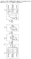
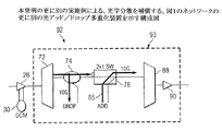
図1は、例示的な光ネットワーク10を示す。光ネットワーク10は、光ネットワーク10の構成部分によって通信される1つ又は複数の光信号を伝送するよう動作可能な1つ又は複数の光ファイバー28を含む。光ファイバー28によって互いに結合される光ネットワーク10の構成部分は、終端ノード12a及び12b、並びに1つ又は複数の光アッド/ドロップ多重化装置(OADM)31(例えば、OADM31a及び31b)を含む。光ネットワーク10は終端ノードを備えたポイントツーポイント光ネットワークとして示すが、光ネットワーク10は、リング型光ネットワーク、メッシュ型光ネットワーク、又は何れかの他の適切な光ネットワーク、若しくは光ネットワークの組み合わせとして構成することもできる。光ネットワーク10は、短距離メトロポリタン・ネットワーク、都市間長距離ネットワーク、又は何れかの他の適切なネットワーク、若しくはネットワークの組み合わせにおいて用いることができる。
FIG. 1 shows an exemplary optical network 10. The optical network 10 includes one or more optical fibers 28 operable to transmit one or more optical signals communicated by components of the optical network 10. The components of optical network 10 that are coupled together by optical fiber 28 include
終端ノード12aは、送信器14及び16、多重化装置18、並びに増幅器26を含む。送信器14及び16は、光信号を送信するよう動作可能な何れかの送信器又は他の適切な装置を含む。各送信器14又は16は、情報を受信し、光の1つ又は複数の波長を変調してその波長上の情報を符号化する。光ネットワーキングでは、光の波長はチャネルとも呼ばれている。各送信器14又は16も、関連付けられた波長上で光学的に符号化されたこの情報を送信するよう動作可能でもある。多重化装置18は、別々のチャネルを一信号に合成するよう動作可能な何れかの多重化装置、若しくは多重化装置の組み合わせ、又は他の装置を含む。多重化装置18は、ファイバー28に沿って通信するよう、送信器14及び16によって送信される異なるチャネルを光信号に合成するよう動作可能である。
The
増幅器26を用いてマルチチャネル信号を増幅することができる。増幅器26を、特定の長さのファイバー29の前及び/又は後に配置させることができる。増幅器26は、光信号を増幅する光中継器を備え得る。この増幅は、光・電気変換又は電気・光変換なしで行うことができる。特定の実施例では、増幅器26は稀土類元素によって添加された光ファイバーを備え得る。信号がファイバーを通過すると、光ファイバーの添加部分の原子を励起するよう外部エネルギが印加され、それによって、光信号の強度が増加する。例として、増幅器26はエルビウム添加ファイバー増幅器(EDFA)を備え得る。しかし、何れかの他の適切な増幅器26を用いることができる。
The
単一の光信号の複数チャネルで情報を通信する処理は、光学では、波長分割多重化(WDM)として呼ばれている。高密度波長分割多重化(DWDM)は、通常、40を上回る多数(高密度)の波長をファイバーに多重化することを表す。WDM、DWDMや他の複数波長伝送手法を光ネットワークにおいて用いて光ファイバー毎の合計帯域幅を増加させる。WDM又はDWDMなしでは、ネットワークにおける帯域幅は単に一波長のビットレートに制限されることになる。帯域幅が大きいほど、光ネットワークはより多くの量の情報を送信することができる。図1をもう一度参照すれば、光ネットワーク10における終端ノード12aは、WDM、DWDM、又は他の適切なマルチチャネル多重化手法を用いて、異なるチャネルを送信し、多重化し、マルチチャネル信号を増幅するよう動作可能である。
The process of communicating information over multiple channels of a single optical signal is called optical wavelength division multiplexing (WDM). Dense wavelength division multiplexing (DWDM) typically refers to multiplexing more than 40 (dense) wavelengths into a fiber. Use WDM, DWDM and other multi-wavelength transmission techniques in optical networks to increase the total bandwidth per optical fiber. Without WDM or DWDM, the bandwidth in the network will be limited to just a single bit rate. The higher the bandwidth, the more information can be transmitted by the optical network. Referring back to FIG. 1, the terminating
前述のように、光ネットワークを介して送信することが可能な情報量は、情報によって符号化され、一信号に多重化される光チャネルの数によって直接変動する。よって、WDMを用いる光信号は、単に一チャネルを介して情報を搬送する光信号よりも多くの情報を搬送し得る。DWDMはなお多くの情報を搬送し得る。搬送されるチャネル数に加えて、光ネットワークを介して伝送することが可能な情報量に影響を及ぼす別の要因は、伝送のビットレートである。ビットレートが大きいほど、より多くの情報を伝送することができる。 As described above, the amount of information that can be transmitted over an optical network directly varies depending on the number of optical channels encoded with information and multiplexed into one signal. Thus, an optical signal using WDM can carry more information than an optical signal that carries information only over one channel. DWDM can still carry a lot of information. In addition to the number of channels carried, another factor that affects the amount of information that can be transmitted over an optical network is the bit rate of transmission. The larger the bit rate, the more information can be transmitted.
光ネットワーク容量における拡充及び更新は、一光信号に多重化される波長の数の増加又は各波長上で進む情報のビットレートの増加を伴う。何れの場合も、通常、光システム全体を置き換えるよりも既存のネットワーク構成部分を使用、修正又は追加するほうが費用効率は高い。光システムの更新の費用に関する理由で、更新は場合によっては、より大きい帯域幅を提供する新たな技術及びより小さな帯域幅を提供する旧い技術をサポートしなければならない段階において行わなければならない。 Expansion and update in optical network capacity is accompanied by an increase in the number of wavelengths multiplexed into one optical signal or an increase in the bit rate of information traveling on each wavelength. In either case, it is usually more cost effective to use, modify or add existing network components than to replace the entire optical system. For reasons related to the cost of updating optical systems, updates may sometimes need to be made at a stage where new technologies that provide greater bandwidth and older technologies that provide less bandwidth must be supported.
今日、既存の多くのネットワークは、毎秒10ギガビット(GB/秒)で情報を伝送し、例えば、ノンリターンツーゼロ(NRZ)変調手法を用いて情報を変調する。信号伝送の更新は、例えば、光信号を変調するための差動位相シフト・キーイング(DPSK)又は差動直交位相シフト・キーイングを用いて40GB/秒で情報を伝送することを含む。光ネットワーク全体の送信器の更新は、大半の光ネットワーク・オペレータにとって法外に高いことになるため、そうしたオペレータの多くは、代わりに、40GB/秒のDPSK送信器又はDQPSK送信器によって既存の10GB/秒のNRZ送信器を一定数ずつ置き換える(これらのタイプの送信器は例としてのみ用いている)ことによってそのネットワークを更新することを望んだ。 Today, many existing networks transmit information at 10 gigabits per second (GB / s) and modulate information using, for example, non-return to zero (NRZ) modulation techniques. Signal transmission updates include, for example, transmitting information at 40 GB / s using differential phase shift keying (DPSK) or differential quadrature phase shift keying to modulate the optical signal. Because the update of transmitters across the optical network will be prohibitively expensive for most optical network operators, many of these operators instead use the existing 10 GB with a 40 GB / s DPSK or DQPSK transmitter. We wanted to update the network by replacing a certain number of NRZ transmitters per second (these types of transmitters are only used as examples).
更新された送信器を既存の送信器と一体化させるという、費用効率の高いストラテジを実施したい者が直面する問題の1つに、光学分散補償の問題がある。既存のWDMネットワーク及びDWDMネットワークでも、違う波長から成る光信号は、光学分散を受ける。光学分散は、光信号を、異なる周波数を備えたそのスペクトル成分に分離することを表す。異なる波長は異なる速度で伝搬するため、光学分散が生じる。光信号が既存の光ネットワークにわたって進み、光学分散を受けると、最適又は近最適な特性を達成するよう「完全な」光学分散補償を受け得る。本明細書及び特許請求の範囲では、「完全な」光学分散補償は、特定の変調手法についての最適又は近最適な光学分散補償を表す。特に設計された分散補償ファイバーは、同じ変調手法を用いて変調されたチャネルから成る光信号における分散を補償するよう開発されている。 One problem faced by those wishing to implement a cost-effective strategy of integrating an updated transmitter with an existing transmitter is the problem of optical dispersion compensation. In existing WDM networks and DWDM networks, optical signals having different wavelengths are subjected to optical dispersion. Optical dispersion refers to separating an optical signal into its spectral components with different frequencies. Different wavelengths propagate at different speeds, resulting in optical dispersion. As an optical signal travels across an existing optical network and undergoes optical dispersion, it can undergo “perfect” optical dispersion compensation to achieve optimal or near-optimal characteristics. As used herein and in the claims, “perfect” optical dispersion compensation represents optimal or near-optimal optical dispersion compensation for a particular modulation technique. Specially designed dispersion compensating fibers have been developed to compensate for dispersion in optical signals consisting of channels modulated using the same modulation technique.
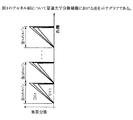
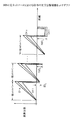
更新された送信器も既存の送信器も用いるシステムは、別々の変調手法を用いるチャネルに対して光学分散補償を行う必要がある。生じる問題は、別々の変調手法を用いたチャネルの完全な光学分散補償が異なり得ることである。例えば、このことは、図2A及び図2Bに示すように、NRZ変調を用いて変調されたチャネル、及び、DPSK変調又はDQPSK変調を用いて変調されたチャネルにあてはまる。 Systems that use both updated and existing transmitters need to compensate for optical dispersion for channels that use different modulation techniques. The problem that arises is that the complete optical dispersion compensation of the channel using different modulation techniques can be different. For example, this applies to a channel modulated using NRZ modulation and a channel modulated using DPSK modulation or DQPSK modulation, as shown in FIGS. 2A and 2B.
前述のように、図2A及び図2Bにおけるグラフは、別々の2つのWDM光信号(10GB/秒のNRZ信号、及び40GB/秒のDPSK信号又はDQPSK信号)の最適な光学分散補償における差を示す。グラフの垂直軸は、累算光学分散を表す。グラフの水平軸は、光信号が進んだ距離(信号が進んだ光ファイバ・スパン数)を表す。ΔDLは、最適な特性の場合の、各スパン後に信号が表す残留光学分散を表す。 As mentioned above, the graphs in FIGS. 2A and 2B show the difference in optimal optical dispersion compensation of two separate WDM optical signals (10 GB / sec NRZ signal and 40 GB / sec DPSK signal or DQPSK signal). . The vertical axis of the graph represents the accumulated optical dispersion. The horizontal axis of the graph represents the distance traveled by the optical signal (number of optical fiber spans traveled by the signal). ΔD L represents the residual optical dispersion represented by the signal after each span for optimal characteristics.
図2Aは、その信号の特性を最適にすることになる10GB/秒のNRZチャネル組を備える信号の光学分散マップを示す。図2Aに示すように、10GB/秒のNRZチャネルは、不足補償される場合、最適な特性を有する。すなわち、光信号がスパン毎に正のΔDLを表すように各スパン後に光信号において光学分散補償を行うことは、10GB/秒のNRZチャネルの最適な特性につながる。 FIG. 2A shows an optical dispersion map of a signal with a 10 GB / sec NRZ channel set that will optimize the characteristics of the signal. As shown in FIG. 2A, the 10 GB / sec NRZ channel has optimal characteristics when undercompensated. That is, performing optical dispersion compensation on an optical signal after each span so that the optical signal represents a positive ΔD L for each span leads to optimal characteristics of the 10 GB / sec NRZ channel.
図2Bに示すように、40GB/秒のDPSKチャネル組又はDQPSKチャネル組を備える信号は、チャネルが100%補償を受ける場合に最適な特性を有する。すなわち、光信号がスパン毎にゼロのΔDLを表すように各スパン後に光信号に対して光学分散補償を行うことによって、40GB/秒のDPSKチャネル又はDQPSKチャネルの最適な特性につながる。 As shown in FIG. 2B, a signal with a 40 GB / sec DPSK channel set or DQPSK channel set has optimal characteristics when the channel is 100% compensated. In other words, optical dispersion compensation is performed on the optical signal after each span so that the optical signal represents zero ΔD L for each span, which leads to optimum characteristics of the 40 GB / sec DPSK channel or DQPSK channel.
図2A及び図2Bに示すように、完全な光学分散補償は、DPSK/DQPSK変調形式を用いたチャネルの場合とは、NRZ変調形式を用いたチャネルの場合は異なる。なお、再度述べることとするが、「完全な」光学分散補償は、特定の変調手法についての最適又は近最適な光学分散補償を表す。既存のネットワークでは、光学分散補償装置は、NRZ形式などの一変調形式を用いて、完全な光学分散補償を信号に対して行う。DPSK/DQPSK形式などの別の変調形式を用いる、更新された送信器が、ネットワークにおいて既存のNRZ送信器の傍らに組み入れられる場合、既存の光学分散補償装置は、更新された光信号の完全な光学分散補償を行わないことになる。 As shown in FIGS. 2A and 2B, complete optical dispersion compensation is different for a channel using the NRZ modulation format than for a channel using the DPSK / DQPSK modulation format. Again, “perfect” optical dispersion compensation represents optimal or near-optimal optical dispersion compensation for a particular modulation technique. In an existing network, an optical dispersion compensation device performs complete optical dispersion compensation on a signal using one modulation format such as the NRZ format. If an updated transmitter using another modulation format such as DPSK / DQPSK format is incorporated alongside an existing NRZ transmitter in the network, the existing optical dispersion compensator will Optical dispersion compensation is not performed.
例えば、先行して全てNRZであったネットワークにおける既存の光学分散補償装置は、NRZチャネルの完全な光学分散補償を行い、DPSK/DQPSKチャネルの不完全な光学分散補償を行うことになる。別の光学分散補償装置に信号を通すことによって、DPSK/DQPSKの完全な光学分散補償をもたらす(残留光学分散がゼロに近い場合)が、既に補償されたNRZ信号における光学分散を過補償することになる。以下に記載する、本発明の実施例は、異なる変調形式を用いたチャネルを搬送する信号における完全な光学分散補償を備えるという問題に対処するものである。 For example, an existing optical dispersion compensator in a network that has previously been all NRZ performs complete optical dispersion compensation of the NRZ channel and incomplete optical dispersion compensation of the DPSK / DQPSK channel. By passing the signal through another optical dispersion compensator, complete DPSK / DQPSK optical dispersion compensation (if the residual optical dispersion is close to zero), but overcompensating the optical dispersion in the already compensated NRZ signal become. The embodiments of the invention described below address the problem of providing complete optical dispersion compensation in signals carrying channels using different modulation formats.
図1中の例示的な実施例をもう一度参照すれば、ノード12aによって生成されるWDM信号は、別々の変調形式を用いるチャネル組を含む。特に、WDM信号は、NRZ変調を用いて10GB/秒で情報を通信するチャネル組と、DPSK変調又はDQPSK変調を用いて40GB/秒で情報を通信するチャネル組とを備える。しかし、異なるチャネル組は、何れかの適切なビットレートで、及び/又は何れかの適切な変調手法を用いて情報を通信することができる。例えば、1つ又は複数のチャネルは、10GB/秒、20GB/秒、40GB/秒、80GB/秒、80超GB/秒のレート、又は何れかの他の適切なビットレートで情報を更に通信することができる。1つ又は複数のチャネルは更に、リターンツーゼロ(RZ)、キャリア抑制リターンツーゼロ(CS‐RZ)、NRZ、DPSK、DQPSKや何れかの他の適切な変調手法などの変調手法を用いて情報を更に通信することができる。本明細書及び特許請求の範囲では、チャネル「組」は、1つ又は複数のチャネルを含み得るものであり、チャネル間の何れかの空間的関係又は何れかの他の、規定していない関係(例えば、組内のチャネルが隣接していなくてもよい)を示唆するものでない。更に、本明細書及び特許請求の範囲に記載されているように、「情報」は、ネットワークにおいて通信、記憶又はソートされる何れかの情報を含み得る。この情報は、オーディオ、ビデオ、テキスト、リアルタイム、非リアルタイム及び/又は他の適切なデータを符号化するよう少なくとも1つの特性を変調させている場合がある。更に、光ネットワーク10において通信される情報は、フレーム、パケット又は非構造化ビット・ストリームとして構成されるものに限定されないが、それらを含む何れかの適切なやり方で構造化し得る。
Referring back to the exemplary embodiment in FIG. 1, the WDM signal generated by
マルチチャネル信号が終端ノード12aから送信された後、信号は光ファイバー28を介してOADM31に進む。光ファイバー28は、適宜、単一の一方向のファイバー、単一の双方向のファイバー、又は複数の一方向若しくは双方向のファイバーを含み得る。本明細書は、単純にするために、一方向のトラフィックをサポートする光ネットワーク10の実施例に焦点を当てているが、本発明は、光ネットワーク10に沿って逆方向に情報を送信することをサポートするために以下に説明する構成部分の適切に修正された実施例を含む双方向システムを更に想定している。
After the multi-channel signal is transmitted from the
OADM31は、増幅器26及び関連した光学分散補償モジュール30(DCM)、並びにアッド/ドロップ多重化装置(ADM)32を含む。前述の通り、増幅器26は、光ネットワーク10をWDM信号が通って進むにつれて増幅するのに用いることができる。DCM30は、信号、又は一変調手法を用いる信号を備えるチャネル組に対して光学分散補償を行うよう動作可能な何れかの分散補償ファイバー(DCF)や他の分散補償装置を含む。NRZやDPSK/DQPSKなどの別々の変調手法を用いたチャネルを備える信号の場合、DCM30は、一変調手法を用いた一チャネル組に対する完全な光学分散補償、及び別の変調手法を用いた別のチャネル組に対する不完全な光学分散補償を行うよう動作可能であり得る。
The OADM 31 includes an
前述のように、かつ図2A及び図2Bを参照すれば、DCM30は違ったふうに変調されたチャネルについて異なる結果をもたらすが、それは、NRZ変調チャネル及びDPSK/DQPSK変調チャネルが、異なるレベルの残留光学分散によって最適に機能する。NRZ変調チャネルが、ある程度の残留分散によって最適に機能する一方、DPSK/DQPSK変調チャネルは、残留分散なしで最適に機能する。図1の例示的な実施例では、DCM30は、10GB/秒のNRZチャネルに対して、完全な分散補償を行い、40GB/秒のDPSK/DPQSKチャネルに対して、不完全な分散補償を行う。光ネットワーク10は、DCM30がそれぞれの増幅器26に結合されているものとして示しているが、DCM30は、増幅器26から別個に配置させることもできる。
As described above and with reference to FIGS. 2A and 2B,
ADM32は、ファイバー28との間で光信号のアッド及び/又はドロップを行うよう動作可能な何れかの装置、又は装置の組み合わせを含み得る。ADM32は、関連したDCM30によって分散補償が完了していない、光信号内の1つ又は複数のチャネル組における光学分散補償を完了するよう動作可能な何れかの、装置、又は装置の組み合わせも含み得る。ADM32の種々の実施例を備える構成部分は、図3、図4及び図5に関して以下に更に全面的に説明する。やはり、本明細書記載の「完全な」光学分散補償は、特定の変調手法についての最適光学分散補償又は近最適光学分散補償を表す。
The
信号は、OADM31を通過した後、ファイバー28に沿って、終端ノード12bに直接進み得るか、又は、1つ又は複数の更なるOADM31(例えば、OADM31bなど)を通過してから終端ノード12bに達し得る。終端ノード12bは、光ネットワーク10を介して伝送される信号を受信するよう動作可能である。終端ノード12bは、増幅器26と、関連したDCM30と、逆多重化装置20と、受信器22及び24とを含む。前述の通り、増幅器26は、光ネットワーク10をWDM信号が通って進むにつれ、増幅するのに用い得るものであり、DCM30は、一変調手法を用いる信号を備えるチャネル組に対して完全な光学分散補償を行い得る。やはり、光ネットワーク10は、個別の増幅器26にDCM30が結合していることを示しているが、DCM30は、増幅器26から別個に配置させることもできる。
The signal may pass directly through the OADM 31 and then directly along the fiber 28 to the
逆多重化装置20は、WDM、DWDMや他の適切なマルチチャネル多重化手法を用いて多重化された異なるチャネルを分離するよう動作可能な何れかの逆多重化装置や他の装置を含む。逆多重化装置20は、複数の多重化チャネルを搬送する光信号を受信し、光信号内の異なるチャネルを逆多重化し、異なるチャネルを別々の受信器22及び24に送るよう動作可能である。 Demultiplexer 20 includes any demultiplexer or other device that is operable to separate different channels multiplexed using WDM, DWDM, or other suitable multi-channel multiplexing techniques. The demultiplexer 20 is operable to receive optical signals carrying multiple multiplexed channels, demultiplex different channels within the optical signal, and send the different channels to separate receivers 22 and 24.
受信器22及び24は、光信号を受信するよう動作可能な何れかの受信器や他の適切な装置を含む。各受信器22又は24は、符号化情報を搬送する光信号のチャネルを受信し、上記情報を電気信号に復調するよう動作可能である。受信器22又は24によって受信されるこうしたチャネルは、送信器14及び16によって送信されるチャネル及び/又はADM32によってアッドされるチャネルを含み得る。
Receivers 22 and 24 include any receiver or other suitable device operable to receive an optical signal. Each receiver 22 or 24 is operable to receive a channel of an optical signal carrying encoded information and demodulate the information into an electrical signal. Such channels received by receiver 22 or 24 may include channels transmitted by
前述の通り、DCM30は、一変調手法を用いる信号を備えるチャネル組のみを完全に補償する。例示的な光ネットワーク10では、終端ノード12bでのDCM30は、10GB/秒のNRZチャネル組についてのみ光学分散補償を完了する。図1中の光ネットワーク10に示していないが、40GB/秒のDPSK/DQPSKチャネルは、例えば、受信器24で、チューニング可能な分散補償器を用いて終端ノード12bで補償することもできる。よって、10GB/秒のNRZも40GB/秒のDPSK/DQPSK信号も、完全な光学分散補償を受ける。
As described above, the
動作上、終端ノード12aの送信器14及び16は、別々のチャネルを介して、異なるビットレートで、及び/又は、別々の変調手法を用いて情報を送信する。多重化装置18は、これらの別々のチャネルを光信号に合成し、光ファイバー28を介してこの信号を通信する。増幅器26は、光信号を受信し、光ファイバー28を介してこの信号を送る。光ファイバー28はこの信号をOADM31aに伝送する。OADM31aの増幅器26はこの信号を受信し、この信号を増幅し、この信号をOADM31aのDCM30に送る。やはり、OADM31aの増幅器26は、DCM30とは別個に、DCM30の前に、又はDCM30の後に配置させることができる。
In operation, the
OADM31aのDCM30は、この信号を受信し、この信号に対して光学分散補償を行う。前述の通り、DCM30は、違ったふうに変調されたチャネル組両方を最適に補償することが可能でない。図1の例示的な実施例では、DCM30は、10GB/秒のNRZチャネルに対して完全な分散補償を行い、40GB/秒のDPSKチャネル又はDQPSKチャネルに対して不完全な分散補償を行い、この光信号を転送する。NRZチャネルの完全な分散補償は、10GB/秒のNRZチャネルにおける最適な分散補償についての、図2Aに示す結果に相互に関連している。
The
DCM30がこの信号に対して光学分散補償を行い、この信号を転送した後、OADM31aのADM32がこの信号を受信する。この光信号を受信した後、ADM32は、光信号との間でチャネルのドロップ及び/又はアッドを行い得る。ADM32は又、DCM30によって分散補償が完了されなかったチャネルに対して光学分散補償を完了する。図1の例示的な実施例では、ADM32は、40GB/秒のDPSK/DQPSKチャネルに対する光学分散補償を完了する。DPSK/DQPSKチャネルにおける完全な光学分散は、40GB/秒のDPSK/DQPSKチャネルにおける最適な分散補償の場合の、図2Bに示す結果に相互に関連している。ADM32は、1つ又は複数の補償されたNRZチャネル又はDPSK/DQPSKチャネル、及び1つ又は複数のアッドされたチャネル(チャネルがADM32にアッドされた場合)を備える信号を次いで転送する。例示的な光ネットワーク10には1つ又は複数のOADM31が存在し得る。
After the
信号が1つ又は複数のOADM31(例えば、OADM31a及び31bなど)を通過した後、終端ノード12bのDCM30は、転送された信号を受信し、信号に対して光学分散補償を行う。前述の通り、DCM30は、違ったふうに変調されたチャネル組両方を最適に補償することが可能でない。図1の例示的な実施例では、DCM30は、10GB/秒のNRZチャネルに対して完全な分散補償を行い、40GB/秒のDPSKチャネル又はDQPSKチャネルに対して不完全な分散補償を行い、光信号を転送する。
After the signal passes through one or more OADMs 31 (eg,
終端ノード12bの逆多重化装置20は、この信号を受信し、この信号を信号の構成チャネルに逆多重化し、この信号の構成チャネルを通す。各チャネルは、終端ノード12bの、関連した受信器22又は24によって受信され、転送される。図1に示していないが、完全な光学分散補償は、終端ノード12bでDCM30によって補償されていない逆多重化チャネル組に対して行い得る。図1の例示的な実施例では、こうしたチャネルは、終端ノード12bで受信される、不完全に補償された40GB/秒のDPSK/DQPSK信号になる。
The demultiplexer 20 at the
前述の通り、光ネットワーク10は、終端ノードを備えたポイントツーポイント光ネットワークとして示しているが、リング型光ネットワーク、メッシュ型光ネットワーク、又は何れかの他の適切な光ネットワーク、若しくは光ネットワークの組み合わせも構成することができる。 As described above, the optical network 10 is shown as a point-to-point optical network with termination nodes, but a ring optical network, a mesh optical network, or any other suitable optical network or optical network Combinations can also be configured.
なお、特定の構成部分を示しているが、本発明の範囲から逸脱することなく、修正、追加又は省略を光ネットワーク10に行うことができる。光ネットワーク10の構成部分は、特定の必要性に応じて一体化させる、又は分離することができる。更に、光ネットワーク10の動作は、より多くの構成部分、より少ない構成部分、又は他の構成部分であり得る。 Although specific components are shown, modifications, additions or omissions can be made to the optical network 10 without departing from the scope of the present invention. The components of the optical network 10 can be integrated or separated according to specific needs. Furthermore, the operation of the optical network 10 can be more components, fewer components, or other components.
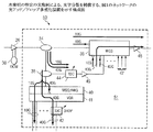
図3は、本発明の特定の実施例による、光学分散を補償するOADM50(図1のネットワークのOADM31の一例)を示す構成図である。OADM50は、図1に示すように、増幅器26及び関連したDCM30を、ADM51(図1に示すADM32の一例)とともに含む。増幅器26及びDCM30は図1の例示的な実施例の説明において前述したが、こうした装置はもう一度説明しないものとする。しかし、増幅器26及びDCM30は図3において、合成されて示しているが、分離することもできる。
FIG. 3 is a block diagram illustrating an OADM 50 (an example of an OADM 31 in the network of FIG. 1) that compensates for optical dispersion, according to a specific embodiment of the present invention. As shown in FIG. 1, the
ADM51は、光ネットワーク10上で光信号を受信し、下記の通り、関連したDCM30によって分散補償が完了していないチャネル組において光学分散補償を完了するよう動作可能である。図3の例示的な実施例では、ADM51は、40GB/秒のDPSK/DQPSKチャネルにおいて完全な光学分散補償を行うよう動作可能である。ADM51は、カプラ34及び38、波長選択スイッチ(WSS)36、関連した可変光減衰器(VOA)41を備えた逆多重化装置40、チューニング可能な分散補償器(TDC)42及び44、並びに増幅器46及び48を含み得る。
The
カプラ34及び38は、光信号を分離するよう動作可能な光ファイバー・カプラ又は他の光構成部分を備え得る。カプラ34及び38は、2つの光信号複製に光信号を分離するよう動作可能である。
WSS36は、複数の光信号を受信し、各信号を信号の構成チャネルに逆多重化し、受信されたゼロ個、1個又は複数のチャネルを終端させ、残りのチャネル、及びアッドされた何れかのチャネルを多重化し、多重化信号を光ネットワーク10に沿って送るよう動作可能な何れかのWSSや他の装置を備え得る。
逆多重化装置40は、光信号を受信し、光信号におけるチャネルを逆多重化するよう動作可能な何れかの装置を備え得る。例えば、逆多重化装置40は、WSS又はアレイ導波路格子(AWG)であり得る。しかし、何れかの他の適切な逆多重化装置40を用いることができる。VOA41は、出力チャネルの電力レベルをバランスさせるよう動作可能なVOA又は何れかの別の装置を備え得る。
TDC42及び44は、別々の変調手法を用いた複数のチャネル組のそれぞれにおいて光学分散を補償するよう動作可能な何れかの装置を備え得る。チューニング可能な装置を説明しているが、何れかの他の適切な補償装置を用いることができる。 TDCs 42 and 44 may comprise any device operable to compensate for optical dispersion in each of a plurality of channel sets using different modulation techniques. Although a tunable device is described, any other suitable compensator can be used.
増幅器46及び48は、図1に関して前述した増幅器26と同じであり得るものであり、よって、再度説明しないものとする。2つの増幅器を例として示しているが、何れかの適切な数の増幅器(適切な場合、増幅器がないケースを含む)を用いることができる。
動作上、増幅器26は、光ネットワーク10上で通信される光信号を受信し、この光信号を増幅し、この光信号をDCM30に転送する。前述の通り、光信号は、1つ又は複数の10GB/秒のNRZチャネル、及び1つ又は複数の40GB/秒のDPSK/DQPSKチャネルを含む。DCM30は光信号を受信し、信号に対して光学分散補償を行う。例示的な実施例では、前述の通り、DCM30は、10GB/秒のNRZチャネル組に対して完全な分散補償を行い、40GB/秒のDPSKチャネル組又はDQPSKチャネル組に対して不完全な分散補償を行う。NRZチャネルの完全な分散補償は、10GB/秒のNRZチャネルにおける最適な分散補償の場合の、図2Aに示す結果と相互に関連している。図2A及び図2Bに示すように、DPSK/DQPSKチャネルが不完全な光学分散補償を受けることをNRZチャネルの完全な光学分散補償は表す。
In operation,
ADM51では、第1のカプラ34は光信号をDCM30から受信し、この光信号を2つの複製に分離し、第1の複製をWSS36に送り、第2の複製をカプラ38にドロップする。WSS36は第1の複製を受信し、40GB/秒のDPSKチャネル又はDQPSKチャネルを(そうしたチャネルは完全に補償されていないので)終端させ、それによって、完全に補償された10GB/秒のNRZチャネルが(特定のNRZチャネルにおいてトラフィックがアッドされない限り)、下記の通り、通ることが可能になる。
In
第2のカプラ38は、第2の複製を受信し、第2の複製を更なる2つの複製(第3の複製及び第4の複製)に分離し、第3の複製を逆多重化装置40にドロップし、第4の複製をTDC44に送る。逆多重化装置40は第3の複製を受信し、第3の複製のチャネルを分離する。VOA41は次いで、分離チャネルのレベルを減衰させて、必要に応じて分離チャネルをバランスさせることができる。各チャネルを次いで、ADM51の1つ又は複数のクライアント装置への通信(又は他の適切な宛先への通信)のために、関連した受信器にドロップすることができ、又は終端させることができる。10GB/秒のNRZチャネルは、NRZチャネルが完全に補償されているので、ADM51の関連受信器に直接ドロップすることができる。しかし、ドロップする対象の何れかの40GB/秒のDPSK/DQPSKチャネルは、更に補償しなければならない。よって、別個のTDC42は、ドロップする対象の40GB/秒のDPSK/DQPSKチャネルを受信し、(図2Bに示すように)40GB/秒のDPSK/DQPSKチャネル毎に光学分散補償を完了し、40GB/秒のチャネルを、関連した受信器に転送する。
The
TDC44は、第4の複製を受信し、(図2Bに示すように)40GB/秒のDPSKチャネル又はDQPSKチャネルに対する分散補償を完了し、第4の複製を増幅器46に転送する。なお、10GB/秒のNRZチャネルは、TDC44に入る前に既に完全に補償されているので、TDC44から出力される10GB/秒のNRZチャネルは過補償される。増幅器46は第4の複製を受信し、第4の複製を増幅し、第4の複製をWSS36に転送する。WSS36は、第4の複製を受信し、10GB/秒のNRZチャネルを(過補償されているので)終端させ、第1の複製からの、完全に補償された10GB/秒のNRZチャネルと、完全に補償された40GB/秒のDPSKチャネル又はDQPSKチャネルを合成する。しかし、WSS36は、ADM51が40GB/秒のチャネルの宛先コードである場合、及び/又は、トラフィックが、(矢印47によって示すように)そのチャネルにおいてADM51でアッドされる場合、特定の40GB/秒のDPSK/DQPSKチャネルを終端させることができる。WSS36は、10GB/秒のNRZチャネルのうちの1つ又は複数において、ADM51から来るトラフィックをアッドすることもできる(この場合、第1の複製におけるこうしたチャネルは終端される)。WSS36は次いで、補償された10GB/秒のNRZチャネル、及び補償された40GB/秒のDPSK/DQPSKチャネル、並びにアッドされた何れかのチャネルを備える新たな光信号を増幅器48に転送する。増幅器48は、新たな光信号を受信し、新たな光信号を増幅し、光ネットワーク10に沿って、新たな光信号を送る。
前述のOADM50は、40GB/秒のDPSK/DQPKチャネル組及び10GB/秒のNRZチャネル組における分散を補償するが、こうした2組のチャネルは、図1の説明において列挙したものを含む、前述のものとは異なるビットレート又は変調形式を有し得る。更に、OADM50は、(例えば、違ったふうに補償する対象の、光信号の更なる複製をカプラ38で作成することによって)別々の変調手法を用いる3組以上のチャネルにおいて光学分散を完全に補償することができる。
The
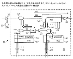
図4は、本発明の別の実施例による、光学分散を補償するOADM70(図1のネットワークのOADM31の一例)を示す構成図である。OADM70は、図1に示すような増幅器26及び関連したDCM30を、ADM71(図1に示すADM32の一例)とともに含む。増幅器26及びDCM30は図1の例示的な実施例の説明において前述したので、これらの装置は再度説明しないものとする。しかし、増幅器26及びDCM30は、図4において、合成されて示しているが、増幅器26及びDCM30は分離することもできる。
FIG. 4 is a block diagram illustrating an OADM 70 (an example of an OADM 31 in the network of FIG. 1) that compensates for optical dispersion according to another embodiment of the present invention.
ADM71は、光ネットワーク10上で光信号を受信し、前述の通り、関連したDCM30によって分散補償が完了していないチャネル組における光学分散補償を完了するよう動作可能である。図4の例示的な実施例では、ADM71は、40GB/秒のDPSK/DQPSKチャネルにおいて完全な光学分散補償を行うよう動作可能である。ADM71は、カプラ52、56及び64と、WSS54と、関連したVOA59及び67それぞれを備える逆多重化装置58及び66と、TDC60と、増幅器62及び68とを含み得る。
The
カプラ52、56及び64は、光信号を分離するよう動作可能な光ファイバー・カプラや他の光構成部分を備え得る。カプラ52、56及び64は、2つの光信号複製に光信号を分離するよう動作可能である。
WSS54は、複数の光信号を受信し、信号の構成チャネルに各信号を逆多重化し、受信されたゼロ個、1個又は複数のチャネルを終端させ、残りのチャネル及び何れかのアッドされたチャネルを多重化し、多重化信号を光ネットワーク10に沿って送るよう動作可能な何れかのWSSや他の装置を備え得る。
逆多重化装置58及び66は、光信号を受信し、光信号におけるチャネルを逆多重化するよう動作可能な何れかの装置を備え得る。例えば、逆多重化装置58及び66はWSS又はAWGであり得る。しかし、何れかの他の適切な逆多重化装置58及び66を用いることができる。VOA59及び67は、出力チャネルの電力レベルをバランスさせるよう動作可能なVOA又は何れかの他の装置を備え得る。
Demultiplexers 58 and 66 may comprise any device operable to receive an optical signal and demultiplex a channel in the optical signal. For example, the
TDC60は、別々の変調手法を用いた複数のチャネル組のそれぞれにおいて光学分散を補償するよう動作可能な何れかの装置を備え得る。チューニング可能な装置を説明しているが、何れかの他の適切な補償装置を用い得る。
The
増幅器62及び68は、図1に関して前述した増幅器26と同じであり得るものであり、よって、再度説明しないものとする。2つの増幅器を例として示しているが、何れかの適切な数の増幅器(適切な場合、増幅器がないケースを含む)を用い得る。
動作上、増幅器26は、光ネットワーク10上で通信される光信号を受信し、光信号を増幅し、光信号をDCM30に転送する。前述の通り、光信号は、1つ又は複数の10GB/秒のNRZチャネル及び1つ又は複数の40GB/秒のDPSK/DQPSKチャネルを含む。DCM30は、光信号を受信し、この信号に対して光学分散補償を行う。例示的な実施例では、前述の通り、DCM30は、10GB/秒のNRZチャネル組に対して完全な分散補償を行い、40GB/秒のDPSKチャネル又はDQPSKチャネルの組に対して不完全な分散補償を行う。NRZチャネルの完全な分散補償は、10GB/秒のNRZチャネルにおける最適な分散補償の場合の、図2Aに示す結果に相互に関連している。図2A及び図2Bに示すように、NRZチャネルの完全な光学分散補償は、DPSK/DQPSKチャネルが不完全な光学分散補償を受けることを意味する。
In operation,
ADM71では、第1のカプラ52は光信号をDCM30から受信し、この光信号を2つの複製に分離し、第1の複製をWSS54に送り、第2の複製をカプラ56にドロップする。WSS54は、第1の複製を受信し、40GB/秒のDPSKチャネル又はDQPSKチャネルを(完全に補償されていないので)終端させ、それによって、下記の通り、(トラフィックが特定のNRZチャネルにおいてアッドされていない限り)完全に補償された10GB/秒のNRZチャネルが通ることが可能になる。
In
第2のカプラ56は、第2の複製を受信し、第2の複製を2つの更なる複製(第3の複製及び第4の複製)に分離し、第3の複製を逆多重化装置58にドロップし、第4の複製をTDC60に送る。逆多重化装置58は第3の複製を受信し、第3の複製のチャネルを分離する。VOA59は次いで、分離されたチャネルのレベルを減衰させて、必要に応じて、分離されたチャネルをバランスさせることができる。10GB/秒のNRZチャネルが完全に補償されているので、10GB/秒のNRZチャネルそれぞれを次いで、ADM71の1つ又は複数のクライアント装置に、(又は他の適切な宛先に)通信するために、関連した受信器に直接ドロップすることができ、又は終端させることができる。40GB/秒のDPSK/DQPSKチャネルは(完全に補償されていないので)全て終端される。
The
TDC60は、第4の複製を受信し、(図2Bに示すように)40GB/秒のDPSKチャネル又はDQPSKチャネルに対する分散補償を完了し、第4の複製を増幅器62に転送する。なお、10GB/秒のNRZチャネルは、TDC60に入る前に既に完全に補償されているので、TDC60から出力された10GB/秒のNRZチャネルは過補償される。増幅器62は第4の複製を受信し、第4の複製を増幅し、第4の複製を第3のカプラ64に転送する。第3のカプラ64は、第4の複製を受信し、第4の複製を更なる2つの複製(第5の複製及び第6の複製)に分離し、第5の複製を逆多重化装置66にドロップし、第6の複製をWSS54に送る。
逆多重化装置66は、第5の複製を受信し、第5の複製のチャネルを分離する。VOA67は次いで、分離されたチャネルのレベルを減衰して、必要に応じて、分離されたチャネルをバランスさせることができる。40GB/秒のDPSK/DQPSKチャネルは完全に補償されているので、40GB/秒のDPSK/DQPSKチャネルそれぞれは次いで、ADM71の1つ又は複数のクライアント装置に、(又は他の適切な宛先に)通信するために、関連した受信器に直接ドロップすることができ、又は終端させることができる。10GB/秒のNRZチャネルは(過補償されているので)全て終端される。
The
WSS54は、第6の複製を受信し、(過補償されているので)10GB/秒のNRZチャネルを終端させ、第1の複製からの完全に補償された10GB/秒のNRZチャネルと、完全に補償された40GB/秒のDPSKチャネル又はDQPSKチャネルを合成する。しかし、WSS54は、ADM71が40GB/秒のチャネルの宛先ノードである場合、及び/又はトラフィックがADM71でそのチャネルにおいて(矢印69によって示すように)アッドされる場合、特定の40GB/秒のDPSK/DQPSKチャネルを終端させることができる。WSS54は、10GB/秒のNRZチャネルの1つ又は複数においてADM71から来るトラフィックをアッドすることもできる(その場合、第1の複製におけるこうしたチャネルは終端される)。WSS54は次いで、補償された10GB/秒のNRZチャネル及び補償された40GB/秒のDPSK/DQPSKチャネル、並びに何れかのアッドされたチャネルを備える新たな光信号を増幅器68に転送する。増幅器68は、新たな光信号を受信し、新たな光信号を増幅し、新たな光信号を光ネットワーク10に沿って送る。
前述のOADM70は、40GB/秒のDPSK/DQPSKチャネル組及び10GB/秒のNRZチャネル組における分散を補償するが、2組のチャネルは、図1の説明において列挙したものを含む、前述のものとは異なるビットレート又は変調形式を有し得る。更に、OADM70は、(例えば、違ったふうに補償する対象の、光信号の更なる複製をカプラ56で作成することによって)別々の変調手法を用いる3組以上のチャネルにおいて光学分散を完全に補償することができる。
The
図5A及び図5Bは、本発明の更に別の実施例による、光学分散を補償するOADM92(図1のネットワークのOADM31の一例)を示す構成図である。以下に更に詳細に説明するように、図5Aは、一変調手法を用いて変調される、特定のチャネル内の信号のOADM92を通る経路を示し、図5Bは、別の変調手法を用いて変調される、特定のチャネル内の信号の、同様なOADM92を通る経路を示す。例示的なネットワーク10では、図5Aは10GB/秒のNRZチャネルの経路を示し、図5Bは40GB/秒のDPSK/DQPSKチャネルの経路を示す。なお、各信号のうちの1つのみ(10GB/秒の1つのNRZ信号及び40GB/秒の1つのDPSK/DQPSK信号)を示しているが、図示した構成部分組を各信号が有する、同じOADM92を通過する複数の10GB/秒のNRZ信号及び40GB/秒のDPSK/DQPSK信号があり得る。
5A and 5B are block diagrams illustrating an OADM 92 (an example of the OADM 31 in the network of FIG. 1) that compensates for optical dispersion, according to yet another embodiment of the present invention. As described in more detail below, FIG. 5A shows the path through
図5A及び図5BのQADM92は、図1に示すような増幅器26及び関連したDCM30を、ADM93(図1に示すADM32の一例)とともに含む。増幅器26及びDCM30は、図1の例示的な実施例の説明において前述したが、これらの装置は再度説明しないものとする。しかし、増幅器26及びDCM30は図5A及び図5Bでは合成して示しているが、増幅器26及びDCM30も分離することができる。
The
図5A及び図5BのADM93は、光ネットワーク10上で光信号を受信し、下記の通り、関連したDCM30によって分散補償が完了していないチャネル組における光学分散補償を完了するよう動作可能である。図5A及び図5Bの例示的な実施例では、ADM93は、40GB/秒のDPSK/DQPSKチャネルにおける完全な光学分散補償を行うよう動作可能である。ADM93は、逆多重化装置72と、多重化装置88と、増幅器90と、カプラ74及び2×1スイッチ76を含む1つ又は複数の構成部分組と、分散補償モジュール(DCM)78と、1×2スイッチ80と、増幅器82と、2×1スイッチ84とを含む1つ又は複数の構成部分組とを含み得る。なお、カプラ74及び2×1スイッチ76は既に、図5A及び図5Bに示すように、ADM93において逆多重化されたチャネル毎に設けることができる。DCM78、1×2スイッチ80、増幅器82、及び2×1スイッチ84は次いで、40GB/秒のDPSK/DQPSKチャネルについてアッドして、図5Bに示すようにこれらのチャネルにおける光学分散補償を完了し得る。
The
逆多重化装置72は、光信号を受信し、光信号の構成チャネルを分離するよう動作可能な何れかの装置を備え得る。例えば、逆多重化装置72はWSS又はAWGであり得る。しかし、何れかの他の適切な逆多重化装置72を用いることができる。
The
カプラ74は、光信号を分離するよう動作可能な光ファイバー・カプラ又は他の光構成部分を備え得る。カプラ74は、光信号を、該光信号の2つの複製に分離するよう構成可能である。
2×1スイッチ76及び84は、2つのソースのうちの一方から光信号を受信し、受信された光信号を一宛先に転送するよう動作可能な2×1スイッチ又は何れかの他の装置を備え得る。2×1スイッチ76又は84が開いている場合、2×1スイッチ76又は84は、第1のソースからの光信号を通し、第2のソースからの光信号を終端させるよう動作可能である。2×1スイッチ76又は84が閉じている場合、2×1スイッチ76又は84は、第2のソースからの光信号を通し、第1のソースからの光信号を終端させるよう動作可能である。
2 × 1
1×2スイッチ80は、光信号を受信し、受信された光信号を2つの宛先のうちの1つに転送するよう動作可能な1×2スイッチ又は何れかの他の装置を備え得る。1×2スイッチ80が開いている場合、1×2スイッチ80は、第1の宛先に受信光信号を転送するよう動作可能であり、受信光信号を第2の宛先に転送するものでない。1×2スイッチ80が閉じている場合、1×2スイッチ80は、受信光信号を第2の宛先に転送するよう動作可能であり、受信光信号を第1の宛先に転送するものでない。
The 1 × 2
DCM78は、1つの変調手法を用いてチャネルに対する光学分散補償を完了するよう動作可能なDCF又は他の装置を含み得る。
増幅器82及び90は、図1に関して前述した増幅器26と同じであり得るものであり、よって、再度説明しないものとする。2つの増幅器を例として示しているが、何れかの適切な数の増幅器(適切な場合、増幅器がないケースも含む)を用いることができる。
多重化装置88は、異なるチャネルを光信号に合成するよう動作可能な何れかの多重化装置又は何れかの他の装置を備え得る。例えば、多重化装置88はAWGであり得る。しかし、何れかの他の適切な多重化装置を用いることができる。
動作上、増幅器26は、光ネットワーク10上で通信される光信号を受信し、この光信号を増幅し、この光信号をDCM30に転送する。前述の通り、光信号は、1つ又は複数の10GB/秒のNRZチャネル、及び1つ又は複数の40GB/秒のDPSK/DQPSKチャネルを含む。DCM30は、光信号を受信し、この信号に対して光学分散補償を行う。例示的な実施例では、前述の通り、DCM30は、10GB/秒のNRZチャネル組に対して完全な分散補償を行い、40GB/秒のDPSKチャネル又はDQPSKチャネルの組に対して不完全な分散補償を行う。NRZチャネルの完全な分散補償は、10GB/秒のNRZチャネルにおける最適な分散補償の場合の、図2Aに示す結果と相互に関連している。図2A及び図2Bに示すように、NRZチャネルの完全な光学分散補償は、DPSK/DQPSKチャネルが、不完全な光学分散補償を受信することを意味する。
In operation,
ADM93では、逆多重化装置72は、光信号を受信し、光信号におけるチャネルを逆多重化する。各チャネルは次いで、その関連したカプラ74に進む。10GB/秒のNRZチャネルのそれぞれに関しては、光学分散補償がこれらのチャネルのそれぞれについて完了しているので、DCM78、1×2スイッチ80、増幅器82及び2×1スイッチ84を含む光構成部分組は、図5Aに示すように、これらのチャネルに設けなくてよい。10GB/秒のNRZチャネルそれぞれがその関連したカプラ74に進んだ後、関連したカプラ74はチャネル内の信号を受信し、信号を2つの複製に分離する。第1の複製は、ADM93の1つ又は複数のクライアント装置に、(又は他の適切な宛先に)通信するために、関連した受信器にドロップするか、又は終端させることができる。第1の複製の終端は、例えば、カプラ74のドロップ・リードが終端される場合、生じることになる。第2の複製は、2×1のスイッチ76に転送することができる。2×1スイッチ76は、第2の複製を終端させるか、又は第2の複製を多重化装置88に送り得る。例えば、2×1スイッチ76は、チャネルのアッド信号85が送信器から2×1スイッチ76で受信される場合、第2の複製を終端させことができる。さもなければ、スイッチ76は第2の複製を通すことができる。
In
図5Bに示すように、40GB/秒のDPSK/DQPSKチャネルのそれぞれに関しては、関連したカプラ74は、チャネル内の信号を受信し、信号を2つの複製に分離し、第1の複製を2×1スイッチ76に送り、第2の複製をDCM78にドロップする。2×1スイッチ76は(補償が完全でないので)第1の複製を終端させる。
As shown in FIG. 5B, for each of the 40 GB / sec DPSK / DQPSK channels, the associated
DCM78は、第2の複製を受信し、第2の複製に対して分散補償を完了し、第2の複製を1×2スイッチ80に転送する。1×2スイッチ80は第2の複製を受信する。40GB/秒のDPSK/DQPSKチャネルは完全に補償されているので、40GB/秒のDPSK/DQPSKチャネルは次いで、ADM93の1つ又は複数のクアイアント装置に、(又は他の適切な宛先に)通信するために、関連した受信器に直接、ドロップすることができる。あるいは、1×2スイッチ80は、チャネル内の信号がこの特定のADM93に宛てられたものでない場合に第2の複製を増幅器82に送り得る。
1×2スイッチ80が第2の複製を通す場合、増幅器82は第2の複製を受信し、第2の複製を増幅し、第2の複製をスイッチ84に転送する。2×1スイッチ84は、第2の複製を受信し、第2の複製をスイッチ76に送る。あるいは、チャネル内の信号がスイッチ80によってドロップされた場合、スイッチ84はそのチャネル内のアッド信号86を受信し、この信号86をスイッチ76に送り得る。2×1スイッチ76は、第2の複製、又はアッドされた信号86を逆多重化装置88に送る。多重化装置88は信号(第2の複製、又はアッドされた信号86)を受信し、この信号を、元の信号(、又は、アッドされた1つ若しくは複数の10GB/秒のNRZ信号85)からの、完全に補償された1つ若しくは複数の10GB/秒のNRZチャネル内の信号、及び/又は他の同様に補償された1つ若しくは複数の40GB/秒のDPSK/DQPSK信号と多重化する。多重化装置88は次いで、多重化された信号を増幅器90に送る。増幅器90は、多重化された信号を受信し、この信号を増幅し、この信号を光ネットワーク10に沿って送る。
If 1 × 2
前述のOADM92は、40GB/秒のDPSK/DQPSK組のうちの1つにおける分散を補償するが、1つのDPSK/DQPSKチャネルの光学分散補償方法を用いて、多重化された他の40GB/秒のDPSKチャネル又はDQPSKチャネルのうちの1つ又は複数における光学分散を補償することも可能である。10GB/秒の1つ又は複数のNRZチャネルを、前述のように、ADM93の両端間で送るか、ADM93でアッドするか、かつ/又はADM93でドロップすることもできる。
The
前述のOADM92は40GB/秒のDPSK/DQPSKチャネル組及び10GB/秒のNRZチャネル組における分散を補償するが、この2組のチャネルは、図1の説明において上記で列挙したものを含む、前述のものとは異なるビットレート又は変調形式を有し得る。更に、OADM92は、別々の変調手法を用いる3組以上のチャネルにおける光学分散を完全に補償し得る。
The
修正、追加又は省略を、本発明の範囲から逸脱することなく前述のOADMに行うことができる。前述のOADMの構成部分は、特定の必要性に応じて一体化させるか、又は分離することができる。更に、OADMの動作は、より多くの、より少ない、又は他の構成部分によって行うことができる。 Modifications, additions, or omissions may be made to the aforementioned OADMs without departing from the scope of the present invention. The aforementioned OADM components can be integrated or separated according to specific needs. Further, OADM operation can be performed by more, fewer, or other components.
図6は、少なくとも2つの別々の変調形式を用いたチャネルを備えた光ネットワークの別の実施例を示す構成図である。図1の例示的なネットワーク10のように、図6の例示的な光ネットワーク100は、別々の変調手法を用いたチャネルを備えた信号における光学分散を最適に補償するという前述の問題に対処する。やはり、この問題は、光ネットワーク・オペレータがそのネットワークを一定部分ずつ更新してネットワーク容量を増やそうとすることによって生じている。特に、このオペレータは、更新された送信器の、既存の送信器との一体化という費用効率の高いストラテジによってネットワーク容量を増やそうとした。このストラテジによって、違ったふうに変調されたチャネルを備えた信号における光学分散を最適に補償するという問題に対する解決策の必要性が生じており、変調の差は、信号を違ったふうに変調する種々のタイプの送信器による。
FIG. 6 is a block diagram illustrating another embodiment of an optical network with channels using at least two separate modulation formats. Like the example network 10 of FIG. 1, the example
図6の例示的なネットワーク100は、違ったふうに変調されたチャネルを備える信号における分散を最適に補償するという問題に対処する例示的なネットワーク10における手法とは別の手法を提供する。例示的なネットワーク10におけるように違ったふうに信号内の、違ったふうに変調されたチャネル組それぞれを補償するかわりに、図6の例示的なネットワーク100は、光信号内のチャネル全てに同じ分散補償を施す。
The
例示的なネットワーク10のように、例示的な光ネットワーク100は、少なくとも2つの別々の変調形式を用いた複数のチャネルを備える信号を搬送するよう動作可能である。光ネットワーク100は、光ネットワーク100の構成部分によって通信される1つ又は複数の光信号を伝送するよう動作可能な1つ又は複数の光ファイバー102も含む。光ファイバー102によって一緒に結合される光ネットワーク100の構成部分は、終端ノード120a及び120b、並びに1つ又は複数の光アッド/ドロップ多重化装置(OADM)140を含む。終端ノード120a及びファイバー102は、図1に関して前述した終端ノード12a及びファイバー28と同じであり得るものであり、よって、再度説明しないものとする。光ネットワーク100は、終端ノードを備えたポイントツーポイント光ネットワークとして示しているが、光ネットワーク100は、リング型光ネットワーク、メッシュ型光ネットワーク、又は何れかの他の適切な光ネットワーク、若しくは光ネットワークの組み合わせとして構成することもできる。光ネットワーク100は、短距離メトロポリタン・ネットワーク、長距離都市間ネットワーク、又は何れかの他の適切なネットワーク、若しくはネットワークの組み合わせにおいて用いることができる。
Like exemplary network 10, exemplary
信号がネットワークにわたって進むにつれ、信号内のチャネル全てが同じ分散補償を受ける例示的なネットワーク100では、各チャネルに施される分散補償量は、交差位相変調(XPM)などの、信号内のチャネル間作用を削減するよう選び得る。ネットワーク100では、チャネル間作用を削減するのに必要な補償は、信号によって搬送される、違ったふうに変調された信号組によって変わってくる場合がある。例として、かつ限定なしで、2組のチャネル(10GB/秒のNRZチャネル及び40GB/秒のDPSK/DQPSKチャネル)それぞれを単一モード・ファイバー(SMF)を介して搬送する信号では、こうした信号に対して一様な不足補償を行うこと、又は、全てのチャネルがゼロ分散を表すようにこうした信号を補償することによって、最適又は近最適にチャネル間作用が削減されない場合があることが実験によって明らかになった。その代わりに、(一部の検査では約110%過補償と約115%過補償との間の)一様な過補償を全てのチャネルに施すことによって、チャネル間作用が最も削減された。しかし、違ったふうに変調された別々のチャネル組を搬送する信号は、チャネル間作用を最適又は近最適に削減するよう別の分散補償を必要とし得る。
In the
こうした結果に照らせば、例示的なネットワーク100の特定の実施例は、10GB/秒のNRZチャネル及び40GB/秒のDPSK/DQPSKチャネルを備える信号に対して一様な分散過補償を、こうした信号がネットワークにわたって進むにつれ、行う。特定の実施例では、10GB/秒のNRZチャネル及び40GB/秒のDPSK/DQPSKチャネルを備える信号は、例えば、約110%と約115%との間の過補償を受け得る。なお、こうした信号におけるチャネルは、OADM140でドロップされるか、又は終端ノード120bで受信される場合に更なる補償を受けて、下記のようにチャネルの特定のデータレート及び/又は変調形式に最適又は近最適な分散補償を備え得る。
In light of these results, a particular embodiment of
例示的なネットワーク100のOADM140は、増幅器110及び関連した光学分散補償モジュール142(DCM)、並びにアッド/ドロップ・モジュール144(ADM)を含む。増幅器110は、図1に関して前述した増幅器26と同じであり得るものであり、よって、再度説明しないものとする。DCM142は、光学分散を過補償するよう動作可能な何れかのDCF、TDC、可変分散補償器(VDC)、又は他の装置を含む。信号は、その特性を向上させるうえで適切な何れかの量、過補償し得る。この量は、例えば、かつ、限定なしで、各DCM142で約110%と約115%との間の過補償を含み得る。例示的なネットワーク100は、DCM142の、それぞれの増幅器110への結合を示すが、DCM142は、増幅器110から別個に配置させることもできる。
The OADM 140 of the
ADM144は、ファイバー102から光信号のアッド及び/又はドロップを行うよう動作可能な何れかの装置、又は装置の組み合わせを含む。ADM144は、例示的なネットワーク100において、信号に対する光学分散補償を完了するよう動作可能な何れかの装置、又は装置の組み合わせも含み得る。ADM144装置は、例えば、上記図3乃至図5に示す装置を含み得る。しかし、図3乃至図5の装置は、(図3乃至図5におけるように、不足補償された40GB/秒のDPSK/DQPSKチャネルに対する光学分散補償を完了することに対して)過補償された40GB/秒のDPSK/DQPSKチャネルに対する光学分散補償を完了するよう修正することが必要になる。
The
例示的なネットワーク100の終端ノード120bは、光ネットワーク100を介して送信された信号を受信し、光学分散についてこうした信号を補償するよう動作可能である。DCM30をDCM142によって置き換える以外は、終端ノード120bは、図1に関して前述した終端ノード12bと同じであり得るものであり、よって再度説明しないものとする。更に、DCM142は、OADM140の説明において前述しているので、再度説明しないものとする。しかし、例示的なネットワーク100は、個別の増幅器110に結合されたDCM142を示すが、DCM142は、増幅器110から別個に配置させることもできる。なお、例示的な光ネットワーク100に示していないが、特定の実施例では、40GB/秒のDPSK/DQPSK信号は、例えば、逆多重化された40GB/秒のDPSK/DQPSK信号が受信器118で受信される前にTDCや他の分散補償装置を用いて終端ノード12bで補償することができる。
The
図7は、図6の光ネットワークにおける信号の光学分散補償を示すグラフである。特に、グラフは、光ネットワーク100のDCM142によって行われる光学分散過補償を示す。垂直軸は、累算光学分散を表す。水平軸は、光信号が進んだ距離(信号が進んだ光ファイバー・スパン数)を表す。ΔDLは、最適な(又は近最適な)特性のために各スパン後に例示的な実施例における信号が表す残留光学分散を表す。
FIG. 7 is a graph showing optical dispersion compensation of signals in the optical network of FIG. In particular, the graph shows the optical dispersion overcompensation performed by the
図7は、各スパン後に例示的なネットワーク100内の信号に対してDCM142が光学分散過補償を行う方法を示す。特定の実施例では、各DCM142は、ファイバー102のスパンにわたって累算された分散よりもΔDL、大きな量で分散を過補償する。よって、信号が進んだ第1のスパン後、DCM142は、累算された分散がΔDLに等しくなるように信号を補償することになる。N個のスパンにわたって、累算された分散はN(ΔDL)に等しい。特定の実施例では、前述のように、終端ノード120bの受信器118によって受信される前に、40GB/秒のDPSK/DQPSK信号は、例えば、更なるTDC(図6に図示していない)などの更なる分散補償装置によって補償することができる。図7は、特定の実施例において、更なる分散補償が、40GB/秒のDPSK/DQPSK信号に対して、こうした装置によって、こうした信号がゼロ累算光学分散を備えるように施される。10GB/秒のNRZ信号は、受信器116によって受信される前に更なる補償を何ら必要としない場合がある。
FIG. 7 illustrates how the
再度図6を参照すれば、動作上、終端ノード120aの送信器104及び送信器106は、別々のチャネルを介して、異なるビットレートで、かつ/又は別々の変調手法を用いて情報を送信する。多重化装置108は、こうした別々のチャネルを光信号に合成し、光ファイバー102を介してこの信号を通信する。増幅器110は、光信号を受信し、この信号を増幅し、光ファイバー102を介してこの信号を送る。光ファイバー102は、この信号をOADM104aに伝送する。OADM140aの増幅器110は、この信号を増幅し、この信号をDCM142に送る。やはり、増幅器は、ネットワーク100上のDCM142とは別個に、DCM142の前に、又はDCM142の後に配置させることができる。
Referring again to FIG. 6, in operation, the
OADM140aのDCM142はこの信号を受信し、この信号に対して光学分散過補償を行う。この信号は、信号の特性を向上させるうえで適切な何れかの量、過補償することができる。この量は、例えば、かつ限定なしで、各DCM142で約110%と約115%との間の過補償を含み得る。
The
DCM142は、信号を、この信号がΔDL過補償を表すように過補償した後、この信号をOADM140aのADM144に転送する。ADM144は、光信号との間でのチャネルのドロップ及び/又はアッドを行い得る。光チャネルの何れかをドロップする前に、ADM144は、例えば、上記図3乃至図5に示す方法を用いることなどによって、チャネルに対して光学分散補償を完了することができる。前述の通り、修正及び追加を、OADM140でドロップされる、過補償されたチャネルに対して(例えば、過補償された40GB/秒のDPSK/DQPSKチャネルに対してなど)完全な光学分散補償を備えるよう図3乃至図5の方法に行うことが必要であり得る。ADM144は次いで、過補償された信号を、ファイバー102を介して転送する。
The
1つ又は複数のOADM(OADM140a及び140bなど)を信号が通過した後、終端ノード120bのDCM142は、転送された信号を受信し、信号に対して光学分散過補償を行う。DCM142は次いで、光信号を逆多重化装置114に転送する。逆多重化装置114は信号を受信し、信号の構成チャネルに信号を逆多重化し、信号の構成チャネルを通す。各チャネルは、終端ノード120bの関連した受信器116又は118によって受信され、転送される。図6に示していないが、特定の実施例では、完全な光学分散補償(約100%補償)を、前述のように終端ノード120bで40GB/秒のDPSK/DQPSKチャネルに対して行うことができる。
After the signal passes through one or more OADMs (such as
修正、追加、又は省略は、本発明の範囲から逸脱することなく、前述のネットワーク100に行うことができる。前述のネットワーク100の構成部分は、特定の必要性に応じて一体化させるか、又は分離することができる。更に、ネットワーク100の動作は、より多くの、より少ない、又は他の構成部分によって行うことができる。
Modifications, additions, or omissions can be made to the
本発明をいくつかの実施例によって説明したが、種々の変更及び修正が当業者に分かり得る。本発明が、特許請求の範囲内に収まる前述の変更及び修正を包含することが意図されている。
(付記1) 光信号の分散補償の方法であって、
複数のチャネルを備える光信号を受信する工程であって、前記チャネルのうちの1つ又は複数の第1の組において通信される情報は第1の変調手法を用いて変調され、前記チャネルのうちの1つ又は複数の第2の組において通信される情報は第2の変調手法を用いて変調される工程と、
前記第1のチャネル組の分散補償が完全であるように、かつ前記第2のチャネル組の分散補償が不完全であるように前記光信号における光学分散を補償する工程と、
前記光信号を少なくとも前記光信号の第1の複製と前記光信号の第2の複製とに分離する工程と、
前記第1の複製における前記第2のチャネル組を終端させる工程と、
前記第2のチャネル組の分散補償が完全であるように前記第2の複製に対して更なる分散補償を行う工程と、
前記第2の複製における前記第1のチャネル組を終端させる工程とを備えることを特徴とする方法。
(付記2) 前記第1のチャネル組において通信される情報は10GB/秒で通信され、
前記第2のチャネル組において通信される情報は40GB/秒で通信されることを特徴とする付記1記載の方法。
(付記3) 前記光信号の前記第1の複製及び前記第2の複製における残りのチャネルを合成して、補償された光信号を形成する工程を更に備えることを特徴とする付記1記載の方法。
(付記4) 前記第2の複製に対して分散補償を行う前に、前記第2の複製を第3の複製及び第4の複製に分離する工程であって、前記更なる分散補償は前記第4の複製に対して行われる工程と、
前記第3の複製の前記チャネルを逆多重化する工程と、
前記第3の複製の前記チャネルのうちの1つ又は複数における情報を1つ又は複数のクライアント装置にドロップする工程とを備えることを特徴とする付記1記載の方法。
(付記5) 前記第2のチャネル組にある、前記クライアント装置にドロップされる前記チャネルの何れかに対して更なる分散補償を行う工程を更に備えることを特徴とする付記4記載の方法。
(付記6) 前記第2の複製に対して分散補償を行う前に、前記第2の複製を第3の複製及び第4の複製に分離する工程であって、前記更なる分散補償が前記第4の複製に対して行われる工程と、
前記第3の複製の前記チャネルを逆多重化する工程と、
前記第3の複製の前記第1のチャネル組のうちの1つ又は複数における情報を1つ又は複数のクライアント装置にドロップする工程と、
前記第2のチャネル組の分散補償が完全であるように前記第4の複製に対して分散補償を行った後、前記第4の複製の前記第2のチャネル組のうちの1つ又は複数における情報を1つ又は複数のクライアント装置にドロップする工程とを更に備えることを特徴とする付記1記載の方法。
(付記7) 複数のチャネルを備える光信号を受信するよう動作可能な光学分散補償システムであって、前記チャネルのうちの1つ又は複数の第1の組において通信される情報は第1の変調手法を用いて変調され、前記チャネルのうちの1つ又は複数の第2の組において通信される情報は第2の変調手法を用いて変調され、
前記第1のチャネル組の分散補償が完全であるように、かつ前記第2のチャネル組の分散補償が不完全であるように前記光信号における光学分散を補償するよう動作可能な第1の分散補償装置と、
前記光信号を前記第1の分散補償装置から受信し、少なくとも前記光信号の第1の複製と前記光信号の第2の複製とに分離するよう動作可能なカプラと、
前記第2の複製を受信し、前記第2のチャネル組の分散補償が完全であるように前記第2の複製に対して更なる分散補償を行うよう動作可能な第2の分散補償装置と、
前記光信号の前記第1の複製内の前記第2のチャネル組を終端させるよう動作可能であり、前記光信号の前記第2の複製内の前記第1のチャネル組を終端させるよう動作可能なスイッチとを備えることを特徴とするシステム。
(付記8) 前記第1のチャネル組において通信される情報は、10GB/秒で通信され、
前記第2のチャネル組において通信される情報は、40GB/秒で通信されることを特徴とする付記7記載のシステム。
(付記9) 前記スイッチは、前記第1の複製及び前記第2の複製における残りのチャネルを合成して、補償された光信号を形成するよう更に動作可能であることを特徴とする付記7記載のシステム。
(付記10) 前記光信号の前記第2の複製を第3の複製及び第4の複製に分離するよう動作可能な第2のカプラ装置であって、前記第2の分散補償装置が、前記第4の複製に対して更なる分散補償を行うよう動作可能である第2のカプラ装置と、
前記第3の複製の前記チャネルを逆多重化し、前記第3の複製の前記チャネルの1つ又は複数における情報を1つ又は複数のクライアント装置にドロップするよう動作可能な逆多重化装置とを更に備えることを特徴とする付記7記載のシステム。
(付記11) 前記逆多重化装置によって前記クライアント装置にドロップされる、前記第2のチャネル組内のチャネルに対して更なる分散補償をそれぞれが動作可能な1つ又は複数の第3の分散補償装置を更に備えることを特徴とする付記10記載のシステム。
(付記12) 前記光信号の前記第2の複製を第3の複製及び第4の複製に分離するよう動作可能な第2のカプラ装置であって、前記第2の分散補償装置が、前記第4の複製に対して更なる分散補償を行う第2のカプラ装置と、
前記第3の複製の前記チャネルを逆多重化し、前記第3の複製の前記チャネルの1つ又は複数における情報を1つ又は複数のクライアント装置にドロップするよう動作可能な逆多重化装置と、
前記第4の複製が前記第2の分散補償装置によって補償された後に、前記第4の複製の前記第2のチャネル組のうちの1つ又は複数における情報を1つ又は複数のクライアント装置にドロップするよう動作可能な第2の逆多重化装置とを更に備えることを特徴とする付記7記載のシステム。
(付記13) 光信号の分散補償の方法であって、
複数のチャネルを備える光信号を受信する工程であって、前記チャネルの1つ又は複数の第1の組において通信される情報が第1の変調手法を用いて変調され、前記チャネルの1つ又は複数の第2の組において通信される情報が第2の変調手法を用いて変調され、
前記第1のチャネル組の分散補償が完全であるように、かつ前記第2のチャネル組の分散補償が不完全であるように前記光信号における光学分散を補償する工程と、
前記光信号を、前記光信号の構成チャネルに逆多重化する工程と、
逆多重化後に、前記第2のチャネル組の分散補償が完全であるように前記第2のチャネル組に対して更なる分散補償を行う工程と、
前記第1のチャネル組及び前記第2のチャネル組を多重化して、補償された光信号を形成する工程とを備えることを特徴とする方法。
(付記14) 前記第1のチャネル組において通信される情報は10GB/秒で通信され、
前記第2のチャネル組において通信される情報は40GB/秒で通信されることを特徴とする付記13記載の方法。
(付記15) 複数のチャネルを備える光信号を受信するよう動作可能な光学分散補償システムであって、前記チャネルのうちの1つ又は複数の第1の組において通信される情報は第1の変調手法を用いて変調され、前記チャネルのうちの1つ又は複数の第2の組において通信される情報は第2の変調手法を用いて変調され、
前記第1のチャネル組の分散補償が完全であるように、かつ前記第2のチャネル組の分散補償が不完全であるように前記光信号における光学分散を補償するよう動作可能な第1の分散補償装置と、
前記光信号を前記第1の分散補償装置から受信し、前記光信号を前記光信号の構成チャネルに逆多重化するよう動作可能な逆多重化装置と、
前記第2のチャネル組におけるチャネルを前記逆多重化装置から受信し、前記チャネル内の前記信号に対して更なる分散補償を、前記チャネル内の前記信号の分散補償が完全であるように行うようそれぞれが動作可能な1つ又は複数の第2の分散補償装置と、
前記第1のチャネル組及び前記第2のチャネル組を多重化して、補償された光信号を形成するよう動作可能な多重化装置とを備えることを特徴とするシステム。
(付記16) 前記第1のチャネル組において通信される情報が10GB/秒で通信され、
前記第2のチャネル組において通信される情報が40GB/秒で通信されることを特徴とする付記15記載のシステム。
(付記17) 光信号の分散補償の方法であって、
複数のチャネルを備える光信号を受信する工程であって、前記チャネルのうちの1つ又は複数の第1の組において通信される情報は第1の変調手法を用いて変調され、前記チャネルのうちの1つ又は複数の第2の組において通信される情報は第2の変調手法を用いて変調される工程と、
前記光信号の前記チャネルの全てにわたって前記光信号における光学分散を一様に過補償する工程とを備えることを特徴とする方法。
(付記18) 前記光信号の前記チャネル全てが、約110%乃至約115%の範囲で一様に過補償されることを特徴とする付記17記載の方法。
(付記19) 前記第1のチャネル組において通信される情報が10GB/秒で通信され、
前記第2のチャネル組において通信される情報が40GB/秒で通信されることを特徴とする付記17記載の方法。
(付記20) 受信器での前記光信号の受信に備えて、かつ分散補償が実質的にゼロであるように前記第2のチャネル組に対して更なる補償を行う工程を更に備えることを特徴とする付記19記載の方法。
(付記21) 光信号の分散補償のシステムであって、
複数のチャネルを備える光信号を受信し、前記チャネルのうちの1つ又は複数の第1の組において通信される情報が第1の変調手法を用いて変調され、前記チャネルのうちの1つ又は複数の第2の組において通信される情報が第2の変調手法を用いて変調され、かつ、
前記光信号の前記チャネル全てにわたって前記光信号における光学分散を一様に過補償するよう動作可能な第1の分散補償装置を備えることを特徴とするシステム。
(付記22) 前記光信号の前記チャネル全てが110%乃至115%の範囲で一様に過補償されることを特徴とする付記21記載のシステム。
(付記23) 前記第1のチャネル組において通信される情報が10GB/秒で通信され、
前記第2のチャネル組において通信される情報が40GB/秒で通信されることを特徴とする付記21記載のシステム。
(付記24) 受信器に関連しており、前記受信器での前記光信号の受信に備えて、かつ分散補償が実質的にゼロであるように前記第2のチャネル組に対して更なる補償を行うよう動作可能な第2の分散補償装置を更に備えることを特徴とする付記23記載のシステム。
While the present invention has been described in terms of several embodiments, various changes and modifications will be apparent to those skilled in the art. The present invention is intended to embrace all such alterations and modifications that fall within the scope of the appended claims.
(Supplementary note 1) A method for dispersion compensation of an optical signal,
Receiving an optical signal comprising a plurality of channels, wherein information communicated in one or more first sets of the channels is modulated using a first modulation technique; Information communicated in one or more second sets of is modulated using a second modulation technique;
Compensating optical dispersion in the optical signal such that dispersion compensation of the first channel set is complete and dispersion compensation of the second channel set is incomplete;
Separating the optical signal into at least a first replica of the optical signal and a second replica of the optical signal;
Terminating the second set of channels in the first replica;
Performing further dispersion compensation on the second replica such that the dispersion compensation of the second channel set is complete;
Terminating the first channel set in the second replica.
(Supplementary Note 2) Information communicated in the first channel set is communicated at 10 GB / second,
The method according to
(Supplementary note 3) The method according to
(Supplementary Note 4) Before performing dispersion compensation on the second replica, separating the second replica into a third replica and a fourth replica, wherein the further dispersion compensation is the first replica The steps performed on 4 copies;
Demultiplexing the channel of the third replica;
The method of
(Supplementary note 5) The method according to supplementary note 4, further comprising the step of performing further dispersion compensation on any of the channels dropped in the client device in the second channel set.
(Supplementary note 6) Before performing dispersion compensation on the second replica, separating the second replica into a third replica and a fourth replica, wherein the further dispersion compensation is the first replica The steps performed on 4 copies;
Demultiplexing the channel of the third replica;
Dropping information in one or more of the first set of channels of the third replica to one or more client devices;
After performing dispersion compensation on the fourth replica such that dispersion compensation of the second channel set is complete, in one or more of the second channel sets of the fourth replica The method according to
(Supplementary note 7) An optical dispersion compensation system operable to receive an optical signal comprising a plurality of channels, wherein information communicated in one or more first sets of the channels is a first modulation. Information modulated using a technique and communicated in a second set of one or more of the channels is modulated using a second modulation technique;
A first dispersion operable to compensate for optical dispersion in the optical signal such that dispersion compensation of the first channel set is complete and dispersion compensation of the second channel set is incomplete. A compensation device;
A coupler operable to receive the optical signal from the first dispersion compensator and to separate at least a first replica of the optical signal and a second replica of the optical signal;
A second dispersion compensator that is operable to receive the second replica and perform further dispersion compensation on the second replica such that the dispersion compensation of the second channel set is complete;
Operable to terminate the second channel set in the first replica of the optical signal and operable to terminate the first channel set in the second replica of the optical signal A system comprising a switch.
(Supplementary Note 8) Information communicated in the first channel set is communicated at 10 GB / second,
The system according to claim 7, wherein information communicated in the second channel set is communicated at 40 GB / second.
(Supplementary note 9) The supplementary note 7, wherein the switch is further operable to combine the remaining channels in the first replica and the second replica to form a compensated optical signal. System.
(Supplementary Note 10) A second coupler apparatus operable to separate the second replica of the optical signal into a third replica and a fourth replica, wherein the second dispersion compensator includes the first replica A second coupler device operable to provide further dispersion compensation for the four replicas;
A demultiplexer operable to demultiplex the channel of the third replica and drop information on one or more of the channels of the third replica to one or more client devices; The system according to appendix 7, which is provided.
(Supplementary Note 11) One or more third dispersion compensations each operable to perform further dispersion compensation on the channels in the second channel set dropped to the client device by the demultiplexing device The system of claim 10, further comprising a device.
(Supplementary note 12) A second coupler apparatus operable to separate the second replica of the optical signal into a third replica and a fourth replica, wherein the second dispersion compensator includes the first replica A second coupler device for further dispersion compensation for four replicas;
A demultiplexer operable to demultiplex the channel of the third replica and drop information in one or more of the channels of the third replica to one or more client devices;
After the fourth replica is compensated by the second dispersion compensator, the information in one or more of the second channel sets of the fourth replica is dropped to one or more client devices The system according to claim 7, further comprising a second demultiplexer operable to operate.
(Supplementary note 13) A method for dispersion compensation of an optical signal,
Receiving an optical signal comprising a plurality of channels, wherein information communicated in one or more first sets of channels is modulated using a first modulation technique, and one or more of the channels Information communicated in a plurality of second sets is modulated using a second modulation technique;
Compensating optical dispersion in the optical signal such that dispersion compensation of the first channel set is complete and dispersion compensation of the second channel set is incomplete;
Demultiplexing the optical signal into the constituent channels of the optical signal;
After demultiplexing, performing further dispersion compensation on the second channel set such that the dispersion compensation of the second channel set is complete;
Multiplexing the first channel set and the second channel set to form a compensated optical signal.
(Supplementary Note 14) Information communicated in the first channel set is communicated at 10 GB / second,
The method according to claim 13, wherein information communicated in the second channel set is communicated at 40 GB / sec.
(Supplementary note 15) An optical dispersion compensation system operable to receive an optical signal comprising a plurality of channels, wherein information communicated in one or more first sets of the channels is a first modulation. Information modulated using a technique and communicated in a second set of one or more of the channels is modulated using a second modulation technique;
A first dispersion operable to compensate for optical dispersion in the optical signal such that dispersion compensation of the first channel set is complete and dispersion compensation of the second channel set is incomplete. A compensation device;
A demultiplexer operable to receive the optical signal from the first dispersion compensator and demultiplex the optical signal into a constituent channel of the optical signal;
Receiving a channel in the second set of channels from the demultiplexer and performing further dispersion compensation for the signal in the channel such that the dispersion compensation of the signal in the channel is complete One or more second dispersion compensators each operable,
And a multiplexing device operable to multiplex the first channel set and the second channel set to form a compensated optical signal.
(Supplementary Note 16) Information communicated in the first channel set is communicated at 10 GB / second,
The system according to claim 15, wherein information communicated in the second channel set is communicated at 40 GB / sec.
(Supplementary note 17) A method for dispersion compensation of an optical signal,
Receiving an optical signal comprising a plurality of channels, wherein information communicated in one or more first sets of the channels is modulated using a first modulation technique; Information communicated in one or more second sets of is modulated using a second modulation technique;
Uniformly overcompensating optical dispersion in the optical signal across all of the channels of the optical signal.
(Supplementary note 18) The method according to supplementary note 17, wherein all the channels of the optical signal are uniformly overcompensated in a range of about 110% to about 115%.
(Supplementary note 19) Information communicated in the first channel set is communicated at 10 GB / second,
The method according to claim 17, wherein information communicated in the second channel set is communicated at 40 GB / second.
(Supplementary note 20) The method further comprises the step of performing further compensation for the second set of channels in preparation for reception of the optical signal at the receiver and so that dispersion compensation is substantially zero. (Supplementary note 19)
(Supplementary note 21) A dispersion compensation system for optical signals,
An optical signal comprising a plurality of channels is received, and information communicated in a first set of one or more of the channels is modulated using a first modulation technique, and one of the channels or Information communicated in a plurality of second sets is modulated using a second modulation technique; and
A system comprising: a first dispersion compensator operable to uniformly overcompensate optical dispersion in the optical signal across all the channels of the optical signal.
(Supplementary note 22) The system according to supplementary note 21, wherein all the channels of the optical signal are uniformly overcompensated in a range of 110% to 115%.
(Supplementary Note 23) Information communicated in the first channel set is communicated at 10 GB / second,
The system according to claim 21, wherein information communicated in the second channel set is communicated at 40 GB / second.
(Supplementary note 24) Further compensation for the second set of channels associated with the receiver, in preparation for receiving the optical signal at the receiver, and so that dispersion compensation is substantially zero. 24. The system according to appendix 23, further comprising a second dispersion compensator operable to perform.
26 増幅器
30 DCM
34 カプラ
36 WSS
38 カプラ
40 逆多重化装置
41 VOA
42 TDC
44 TDC
46 増幅器
48 増幅器
50 OADM
51 ADM
26
34
38
42 TDC
44 TDC
46
51 ADM
Claims (10)
複数のチャネルを備える光信号を受信する工程であって、前記チャネルのうちの1つ又は複数の第1の組において通信される情報は第1の変調手法を用いて変調され、前記チャネルのうちの1つ又は複数の第2の組において通信される情報は第2の変調手法を用いて変調される工程と、
前記第1のチャネル組の分散補償が完全であるように、かつ前記第2のチャネル組の分散補償が不完全であるように前記光信号における光学分散を補償する工程と、
前記光信号を少なくとも前記光信号の第1の複製と前記光信号の第2の複製とに分離する工程と、
前記第1の複製における前記第2のチャネル組を終端させる工程と、
前記第2のチャネル組の分散補償が完全であるように前記第2の複製に対して更なる分散補償を行う工程と、
前記第2の複製における前記第1のチャネル組を終端させる工程とを備えることを特徴とする方法。 An optical signal dispersion compensation method comprising:
Receiving an optical signal comprising a plurality of channels, wherein information communicated in one or more first sets of the channels is modulated using a first modulation technique; Information communicated in one or more second sets of is modulated using a second modulation technique;
Compensating optical dispersion in the optical signal such that dispersion compensation of the first channel set is complete and dispersion compensation of the second channel set is incomplete;
Separating the optical signal into at least a first replica of the optical signal and a second replica of the optical signal;
Terminating the second set of channels in the first replica;
Performing further dispersion compensation on the second replica such that the dispersion compensation of the second channel set is complete;
Terminating the first channel set in the second replica.
前記第1のチャネル組において通信される情報は10GB/秒で通信され、
前記第2のチャネル組において通信される情報は40GB/秒で通信されることを特徴とする方法。 The method of claim 1, wherein
Information communicated in the first channel set is communicated at 10 GB / second,
The information communicated in the second channel set is communicated at 40 GB / sec.
前記第2の複製に対して分散補償を行う前に、前記第2の複製を第3の複製及び第4の複製に分離する工程であって、前記更なる分散補償は前記第4の複製に対して行われる工程と、
前記第3の複製の前記チャネルを逆多重化する工程と、
前記第3の複製の前記チャネルのうちの1つ又は複数における情報を1つ又は複数のクライアント装置にドロップする工程とを備えることを特徴とする方法。 The method of claim 1, wherein
Separating the second replica into a third replica and a fourth replica before performing dispersion compensation on the second replica, wherein the further dispersion compensation is applied to the fourth replica. A process performed on
Demultiplexing the channel of the third replica;
Dropping information on one or more of the channels of the third replica to one or more client devices.
前記第2のチャネル組にある、前記クライアント装置にドロップされる前記チャネルの何れかに対して更なる分散補償を行う工程を更に備えることを特徴とする方法。 The method according to claim 4, wherein
The method further comprising the step of performing further dispersion compensation on any of the channels that are dropped on the client device in the second set of channels.
前記第1のチャネル組の分散補償が完全であるように、かつ前記第2のチャネル組の分散補償が不完全であるように前記光信号における光学分散を補償するよう動作可能な第1の分散補償装置と、
前記光信号を前記第1の分散補償装置から受信し、少なくとも前記光信号の第1の複製と前記光信号の第2の複製とに分離するよう動作可能なカプラと、
前記第2の複製を受信し、前記第2のチャネル組の分散補償が完全であるように前記第2の複製に対して更なる分散補償を行うよう動作可能な第2の分散補償装置と、
前記光信号の前記第1の複製内の前記第2のチャネル組を終端させるよう動作可能であり、前記光信号の前記第2の複製内の前記第1のチャネル組を終端させるよう動作可能なスイッチとを備えることを特徴とするシステム。 An optical dispersion compensation system operable to receive an optical signal comprising a plurality of channels, wherein information communicated in a first set of one or more of the channels uses a first modulation technique Information that is modulated and communicated in a second set of one or more of the channels is modulated using a second modulation technique;
A first dispersion operable to compensate for optical dispersion in the optical signal such that dispersion compensation of the first channel set is complete and dispersion compensation of the second channel set is incomplete. A compensation device;
A coupler operable to receive the optical signal from the first dispersion compensator and to separate at least a first replica of the optical signal and a second replica of the optical signal;
A second dispersion compensator that is operable to receive the second replica and perform further dispersion compensation on the second replica such that the dispersion compensation of the second channel set is complete;
Operable to terminate the second channel set in the first replica of the optical signal and operable to terminate the first channel set in the second replica of the optical signal A system comprising a switch.
複数のチャネルを備える光信号を受信する工程であって、前記チャネルの1つ又は複数の第1の組において通信される情報が第1の変調手法を用いて変調され、前記チャネルの1つ又は複数の第2の組において通信される情報が第2の変調手法を用いて変調され、
前記第1のチャネル組の分散補償が完全であるように、かつ前記第2のチャネル組の分散補償が不完全であるように前記光信号における光学分散を補償する工程と、
前記光信号を、前記光信号の構成チャネルに逆多重化する工程と、
逆多重化後に、前記第2のチャネル組の分散補償が完全であるように前記第2のチャネル組に対して更なる分散補償を行う工程と、
前記第1のチャネル組及び前記第2のチャネル組を多重化して、補償された光信号を形成する工程とを備えることを特徴とする方法。 An optical signal dispersion compensation method comprising:
Receiving an optical signal comprising a plurality of channels, wherein information communicated in one or more first sets of channels is modulated using a first modulation technique, and one or more of the channels Information communicated in a plurality of second sets is modulated using a second modulation technique;
Compensating optical dispersion in the optical signal such that dispersion compensation of the first channel set is complete and dispersion compensation of the second channel set is incomplete;
Demultiplexing the optical signal into the constituent channels of the optical signal;
After demultiplexing, performing further dispersion compensation on the second channel set such that the dispersion compensation of the second channel set is complete;
Multiplexing the first channel set and the second channel set to form a compensated optical signal.
前記第1のチャネル組の分散補償が完全であるように、かつ前記第2のチャネル組の分散補償が不完全であるように前記光信号における光学分散を補償するよう動作可能な第1の分散補償装置と、
前記光信号を前記第1の分散補償装置から受信し、前記光信号を前記光信号の構成チャネルに逆多重化するよう動作可能な逆多重化装置と、
前記第2のチャネル組におけるチャネルを前記逆多重化装置から受信し、前記チャネル内の前記信号に対して更なる分散補償を、前記チャネル内の前記信号の分散補償が完全であるように行うようそれぞれが動作可能な1つ又は複数の第2の分散補償装置と、
前記第1のチャネル組及び前記第2のチャネル組を多重化して、補償された光信号を形成するよう動作可能な多重化装置とを備えることを特徴とするシステム。 An optical dispersion compensation system operable to receive an optical signal comprising a plurality of channels, wherein information communicated in a first set of one or more of the channels uses a first modulation technique Information that is modulated and communicated in a second set of one or more of the channels is modulated using a second modulation technique;
A first dispersion operable to compensate for optical dispersion in the optical signal such that dispersion compensation of the first channel set is complete and dispersion compensation of the second channel set is incomplete. A compensation device;
A demultiplexer operable to receive the optical signal from the first dispersion compensator and demultiplex the optical signal into a constituent channel of the optical signal;
Receiving a channel in the second set of channels from the demultiplexer and performing further dispersion compensation for the signal in the channel such that the dispersion compensation of the signal in the channel is complete One or more second dispersion compensators each operable,
And a multiplexing device operable to multiplex the first channel set and the second channel set to form a compensated optical signal.
複数のチャネルを備える光信号を受信する工程であって、前記チャネルのうちの1つ又は複数の第1の組において通信される情報は第1の変調手法を用いて変調され、前記チャネルのうちの1つ又は複数の第2の組において通信される情報は第2の変調手法を用いて変調される工程と、
前記光信号の前記チャネルの全てにわたって前記光信号における光学分散を一様に過補償する工程とを備えることを特徴とする方法。 An optical signal dispersion compensation method comprising:
Receiving an optical signal comprising a plurality of channels, wherein information communicated in one or more first sets of the channels is modulated using a first modulation technique; Information communicated in one or more second sets of is modulated using a second modulation technique;
Uniformly overcompensating optical dispersion in the optical signal across all of the channels of the optical signal.
複数のチャネルを備える光信号を受信し、前記チャネルのうちの1つ又は複数の第1の組において通信される情報が第1の変調手法を用いて変調され、前記チャネルのうちの1つ又は複数の第2の組において通信される情報が第2の変調手法を用いて変調され、かつ、
前記光信号の前記チャネル全てにわたって前記光信号における光学分散を一様に過補償するよう動作可能な第1の分散補償装置を備えることを特徴とするシステム。 A dispersion compensation system for optical signals,
An optical signal comprising a plurality of channels is received, and information communicated in a first set of one or more of the channels is modulated using a first modulation technique, and one of the channels or Information communicated in a plurality of second sets is modulated using a second modulation technique; and
A system comprising: a first dispersion compensator operable to uniformly overcompensate optical dispersion in the optical signal across all the channels of the optical signal.
Applications Claiming Priority (2)
| Application Number | Priority Date | Filing Date | Title |
|---|---|---|---|
| US11/311,717 | 2005-12-19 | ||
| US11/311,717 US7609969B2 (en) | 2005-12-19 | 2005-12-19 | Method and system for compensating for optical dispersion in an optical signal |
Publications (2)
| Publication Number | Publication Date |
|---|---|
| JP2007174659A true JP2007174659A (en) | 2007-07-05 |
| JP4833818B2 JP4833818B2 (en) | 2011-12-07 |
Family
ID=37845259
Family Applications (1)
| Application Number | Title | Priority Date | Filing Date |
|---|---|---|---|
| JP2006341319A Expired - Fee Related JP4833818B2 (en) | 2005-12-19 | 2006-12-19 | Method and system for compensating optical dispersion in an optical signal |
Country Status (3)
| Country | Link |
|---|---|
| US (1) | US7609969B2 (en) |
| EP (1) | EP1798919A3 (en) |
| JP (1) | JP4833818B2 (en) |
Cited By (10)
| Publication number | Priority date | Publication date | Assignee | Title |
|---|---|---|---|---|
| WO2009013795A1 (en) * | 2007-07-20 | 2009-01-29 | Fujitsu Limited | Optical transmission device, wavelength multiplexing optical communication system, and optical transmission method |
| JP2009077400A (en) * | 2007-09-19 | 2009-04-09 | Fujitsu Ltd | Method and system for compensating for optical dispersion in optical signal |
| JP2009232101A (en) * | 2008-03-21 | 2009-10-08 | Fujitsu Ltd | Light transmission system and dispersion compensation method therefor |
| JP2009246768A (en) * | 2008-03-31 | 2009-10-22 | Nippon Telegr & Teleph Corp <Ntt> | Wave-band cross connect apparatus |
| JP2010124280A (en) * | 2008-11-20 | 2010-06-03 | Kddi Corp | Optical burst signal accommodation light inserting/separating apparatus and optical burst signal accommodation light inserting/separating method |
| JP2011193462A (en) * | 2010-03-12 | 2011-09-29 | Fujitsu Ltd | Method and system for compensating for optical dispersion in optical signal |
| JP2012109653A (en) * | 2010-11-15 | 2012-06-07 | Mitsubishi Electric Corp | Wavelength multiplex transmission device |
| JP2012124551A (en) * | 2010-12-06 | 2012-06-28 | Fujitsu Ltd | Optical transmission device |
| JP2013509136A (en) * | 2009-10-27 | 2013-03-07 | エックステラ コミュニケーションズ,インコーポレイテッド | Separate dispersion compensation for coherent and non-coherent channels |
| JP2019041364A (en) * | 2017-08-25 | 2019-03-14 | 富士通株式会社 | Network management by node-by-node cross phase modulation (xpm) compensation |
Families Citing this family (10)
| Publication number | Priority date | Publication date | Assignee | Title |
|---|---|---|---|---|
| US7609969B2 (en) | 2005-12-19 | 2009-10-27 | Fujitsu Limited | Method and system for compensating for optical dispersion in an optical signal |
| US8095010B2 (en) * | 2005-12-28 | 2012-01-10 | Mosaid Technologies Incorporated | Method and device for tunable optical filtering |
| WO2007073764A1 (en) * | 2005-12-28 | 2007-07-05 | Pirelli & C. S.P.A. | Method and system for tunable optical filtering |
| JP4744312B2 (en) * | 2006-01-31 | 2011-08-10 | 富士通株式会社 | Chromatic dispersion monitoring method and apparatus, and optical transmission system |
| ATE515115T1 (en) * | 2006-11-09 | 2011-07-15 | Pgt Photonics Spa | METHOD AND DEVICE FOR FLAWLESS TUNABLE OPTICAL FILTERING |
| EP2251999B1 (en) * | 2009-05-13 | 2013-08-28 | ADVA Optical Networking SE | Data transmission method and network for transmitting a digital optical signal over optical transmission links and networks |
| JP2011035735A (en) * | 2009-08-03 | 2011-02-17 | Fujitsu Ltd | Transmission apparatus, transmission system, and method of communication |
| US8270835B2 (en) * | 2010-03-31 | 2012-09-18 | Fujitsu Limited | Method and system for reducing cross-phase modulation in an optical signal |
| US20120087661A1 (en) * | 2010-10-12 | 2012-04-12 | Christopher Michael Look | Long Distance Transmission Of Incoherent Optical Signals In An Optical Network |
| CN106130644B (en) * | 2016-07-20 | 2018-04-03 | 上海交通大学 | Frequency-domain equilibrium method based on dispersion overcompensation |
Citations (5)
| Publication number | Priority date | Publication date | Assignee | Title |
|---|---|---|---|---|
| JP2001268056A (en) * | 2000-03-22 | 2001-09-28 | Hitachi Ltd | Optical transmission system and wavelength multiplex/ demultiplex optical transmitter |
| JP2005079826A (en) * | 2003-08-29 | 2005-03-24 | Nippon Telegr & Teleph Corp <Ntt> | Wdm transmission system and wdm transmission method |
| JP2005295126A (en) * | 2004-03-31 | 2005-10-20 | Fujitsu Ltd | Dispersion compensation method and compensation node apparatus |
| JP2006042012A (en) * | 2004-07-28 | 2006-02-09 | Nec Corp | Optical communication device, optical transmission system, and optical transmission method |
| JP2006050640A (en) * | 2004-08-06 | 2006-02-16 | Tyco Telecommunications (Us) Inc | Transmission of optical signals of different modulation formats in discrete band |
Family Cites Families (13)
| Publication number | Priority date | Publication date | Assignee | Title |
|---|---|---|---|---|
| US6567577B2 (en) * | 1998-07-14 | 2003-05-20 | Tyco Telecommunications (Us) Inc. | Method and apparatus for providing chromatic dispersion compensation in a wavelength division multiplexed optical transmission system |
| US6310993B1 (en) * | 1999-12-22 | 2001-10-30 | Avanex Corporation | Method and apparatus for chromatic dispersion compensation and dispersion slope compensation in wavelength division multiplexed systems utilizing a channel separator and virtually imaged phased arrays |
| JP3910003B2 (en) * | 2000-05-29 | 2007-04-25 | 富士通株式会社 | Optical receiving station, optical communication system, and dispersion control method |
| JP4592887B2 (en) * | 2000-08-07 | 2010-12-08 | 富士通株式会社 | Method and system for compensating chromatic dispersion |
| CA2419852A1 (en) * | 2000-08-10 | 2002-02-14 | Siemens Aktiengesellschaft | Optical add drop and dispersion compensation apparatus |
| DE10127345A1 (en) * | 2001-06-06 | 2003-01-16 | Siemens Ag | Optical transmission system for high bit rate transmission of optical signals with dispersion compensation units |
| JP2003298516A (en) * | 2002-03-29 | 2003-10-17 | Fujitsu Ltd | Wavelength dispersion compensation apparatus |
| US7149433B2 (en) * | 2002-06-28 | 2006-12-12 | Infineria Corporation | Upgrade of optical amplifier site to a digital optical network site in an optical transmission network |
| JP4259186B2 (en) * | 2002-08-29 | 2009-04-30 | 住友電気工業株式会社 | Optical transmission system |
| JP4576094B2 (en) * | 2003-03-03 | 2010-11-04 | 富士通株式会社 | Wavelength division multiplexing optical repeater transmission method and repeater |
| DE60304148T2 (en) * | 2003-05-05 | 2006-08-24 | Alcatel | Network element for use in an optical transmission network, in particular in a DWDM transmission network |
| US20060067704A1 (en) * | 2004-09-30 | 2006-03-30 | Fishman Daniel A | Method and apparatus for dispersion management in optical communication systems |
| US7609969B2 (en) | 2005-12-19 | 2009-10-27 | Fujitsu Limited | Method and system for compensating for optical dispersion in an optical signal |
-
2005
- 2005-12-19 US US11/311,717 patent/US7609969B2/en not_active Expired - Fee Related
-
2006
- 2006-10-12 EP EP06021425.1A patent/EP1798919A3/en not_active Withdrawn
- 2006-12-19 JP JP2006341319A patent/JP4833818B2/en not_active Expired - Fee Related
Patent Citations (5)
| Publication number | Priority date | Publication date | Assignee | Title |
|---|---|---|---|---|
| JP2001268056A (en) * | 2000-03-22 | 2001-09-28 | Hitachi Ltd | Optical transmission system and wavelength multiplex/ demultiplex optical transmitter |
| JP2005079826A (en) * | 2003-08-29 | 2005-03-24 | Nippon Telegr & Teleph Corp <Ntt> | Wdm transmission system and wdm transmission method |
| JP2005295126A (en) * | 2004-03-31 | 2005-10-20 | Fujitsu Ltd | Dispersion compensation method and compensation node apparatus |
| JP2006042012A (en) * | 2004-07-28 | 2006-02-09 | Nec Corp | Optical communication device, optical transmission system, and optical transmission method |
| JP2006050640A (en) * | 2004-08-06 | 2006-02-16 | Tyco Telecommunications (Us) Inc | Transmission of optical signals of different modulation formats in discrete band |
Cited By (13)
| Publication number | Priority date | Publication date | Assignee | Title |
|---|---|---|---|---|
| US8213798B2 (en) | 2007-07-20 | 2012-07-03 | Fujitsu Limited | Optical transmission apparatus, wavelength division multiplexing optical communication system and optical transmission method |
| WO2009013795A1 (en) * | 2007-07-20 | 2009-01-29 | Fujitsu Limited | Optical transmission device, wavelength multiplexing optical communication system, and optical transmission method |
| JP2009077400A (en) * | 2007-09-19 | 2009-04-09 | Fujitsu Ltd | Method and system for compensating for optical dispersion in optical signal |
| JP2009232101A (en) * | 2008-03-21 | 2009-10-08 | Fujitsu Ltd | Light transmission system and dispersion compensation method therefor |
| US8265485B2 (en) | 2008-03-21 | 2012-09-11 | Fujitsu Limited | Optical transmission system and method for chromatic dispersion compensation |
| JP2009246768A (en) * | 2008-03-31 | 2009-10-22 | Nippon Telegr & Teleph Corp <Ntt> | Wave-band cross connect apparatus |
| JP2010124280A (en) * | 2008-11-20 | 2010-06-03 | Kddi Corp | Optical burst signal accommodation light inserting/separating apparatus and optical burst signal accommodation light inserting/separating method |
| JP2013509136A (en) * | 2009-10-27 | 2013-03-07 | エックステラ コミュニケーションズ,インコーポレイテッド | Separate dispersion compensation for coherent and non-coherent channels |
| JP2011193462A (en) * | 2010-03-12 | 2011-09-29 | Fujitsu Ltd | Method and system for compensating for optical dispersion in optical signal |
| JP2012109653A (en) * | 2010-11-15 | 2012-06-07 | Mitsubishi Electric Corp | Wavelength multiplex transmission device |
| JP2012124551A (en) * | 2010-12-06 | 2012-06-28 | Fujitsu Ltd | Optical transmission device |
| JP2019041364A (en) * | 2017-08-25 | 2019-03-14 | 富士通株式会社 | Network management by node-by-node cross phase modulation (xpm) compensation |
| JP7062944B2 (en) | 2017-08-25 | 2022-05-09 | 富士通株式会社 | Network management with node-by-node mutual phase modulation (XPM) compensation |
Also Published As
| Publication number | Publication date |
|---|---|
| JP4833818B2 (en) | 2011-12-07 |
| US20070140700A1 (en) | 2007-06-21 |
| US7609969B2 (en) | 2009-10-27 |
| EP1798919A3 (en) | 2013-10-09 |
| EP1798919A2 (en) | 2007-06-20 |
Similar Documents
| Publication | Publication Date | Title |
|---|---|---|
| JP4833818B2 (en) | Method and system for compensating optical dispersion in an optical signal | |
| US7991295B2 (en) | Method and system for compensating for optical dispersion in an optical signal | |
| US8270835B2 (en) | Method and system for reducing cross-phase modulation in an optical signal | |
| US8625996B2 (en) | Optical transmitter, optical transmission method, and wavelength-selective variable delayer | |
| JP5741086B2 (en) | Method and system for compensating for optical dispersion in optical signals | |
| US7693425B2 (en) | Method and system for compensating for optical dispersion in an optical signal in a hybrid optical network | |
| JP5002431B2 (en) | Optical transmission system | |
| JP2009232101A (en) | Light transmission system and dispersion compensation method therefor | |
| US7277648B2 (en) | Network element for use in an optical communication network, in particular a DWDM communication network | |
| JP7047339B2 (en) | Multi-channel optical mutual phase modulation compensator | |
| US8195048B2 (en) | Optical transport system architecture for remote terminal connectivity | |
| US20110103790A1 (en) | Method and System for Compensating for Optical Impairment in an Optical Signal | |
| US7697802B2 (en) | Optical bypass method and architecture | |
| JP2004274615A (en) | Wavelength dispersion compensation system | |
| JP7159561B2 (en) | Low-Noise Achromatic, Directionless, Contention-Free Reconfigurable Optical Add/Drop Multiplexer | |
| US6920277B2 (en) | Optical bypass method and architecture | |
| EP2744134B1 (en) | Method and apparatus for increasing a transmission performance of a hybrid wavelength division multiplexing system | |
| US20110044689A1 (en) | Method and system for cross-phase-modulation noise reduced transmission in hybrid networks | |
| US6571032B1 (en) | Apparatus and method for multiplexing and/or demultiplexing optical signals having substantially equal dispersion | |
| JP7062944B2 (en) | Network management with node-by-node mutual phase modulation (XPM) compensation | |
| CA2414458C (en) | Optical transmission systems including optical amplifiers and methods of use therein |
Legal Events
| Date | Code | Title | Description |
|---|---|---|---|
| A621 | Written request for application examination |
Free format text: JAPANESE INTERMEDIATE CODE: A621 Effective date: 20090907 |
|
| A977 | Report on retrieval |
Free format text: JAPANESE INTERMEDIATE CODE: A971007 Effective date: 20110525 |
|
| A131 | Notification of reasons for refusal |
Free format text: JAPANESE INTERMEDIATE CODE: A131 Effective date: 20110621 |
|
| A521 | Request for written amendment filed |
Free format text: JAPANESE INTERMEDIATE CODE: A523 Effective date: 20110819 |
|
| TRDD | Decision of grant or rejection written | ||
| A01 | Written decision to grant a patent or to grant a registration (utility model) |
Free format text: JAPANESE INTERMEDIATE CODE: A01 Effective date: 20110906 |
|
| A01 | Written decision to grant a patent or to grant a registration (utility model) |
Free format text: JAPANESE INTERMEDIATE CODE: A01 |
|
| A61 | First payment of annual fees (during grant procedure) |
Free format text: JAPANESE INTERMEDIATE CODE: A61 Effective date: 20110922 |
|
| R150 | Certificate of patent or registration of utility model |
Free format text: JAPANESE INTERMEDIATE CODE: R150 |
|
| FPAY | Renewal fee payment (event date is renewal date of database) |
Free format text: PAYMENT UNTIL: 20140930 Year of fee payment: 3 |
|
| LAPS | Cancellation because of no payment of annual fees |