JP2007171933A - Audio signal processing apparatus and method - Google Patents
Audio signal processing apparatus and method Download PDFInfo
- Publication number
- JP2007171933A JP2007171933A JP2006294431A JP2006294431A JP2007171933A JP 2007171933 A JP2007171933 A JP 2007171933A JP 2006294431 A JP2006294431 A JP 2006294431A JP 2006294431 A JP2006294431 A JP 2006294431A JP 2007171933 A JP2007171933 A JP 2007171933A
- Authority
- JP
- Japan
- Prior art keywords
- signal
- audio signal
- noise
- level
- payload
- Prior art date
- Legal status (The legal status is an assumption and is not a legal conclusion. Google has not performed a legal analysis and makes no representation as to the accuracy of the status listed.)
- Ceased
Links
- 230000005236 sound signal Effects 0.000 title claims abstract description 69
- 238000012545 processing Methods 0.000 title claims abstract description 35
- 238000000034 method Methods 0.000 title description 47
- 230000007423 decrease Effects 0.000 claims abstract description 21
- 230000008878 coupling Effects 0.000 claims abstract 3
- 238000010168 coupling process Methods 0.000 claims abstract 3
- 238000005859 coupling reaction Methods 0.000 claims abstract 3
- 230000003247 decreasing effect Effects 0.000 claims abstract 2
- 230000004044 response Effects 0.000 claims description 28
- 238000003672 processing method Methods 0.000 claims 3
- 230000005540 biological transmission Effects 0.000 claims 1
- 239000000463 material Substances 0.000 description 89
- 230000008569 process Effects 0.000 description 32
- 238000001228 spectrum Methods 0.000 description 25
- 239000013598 vector Substances 0.000 description 19
- 230000002123 temporal effect Effects 0.000 description 12
- 238000006243 chemical reaction Methods 0.000 description 10
- 230000000694 effects Effects 0.000 description 9
- 238000012549 training Methods 0.000 description 8
- 230000000875 corresponding effect Effects 0.000 description 7
- 238000001514 detection method Methods 0.000 description 7
- 230000006870 function Effects 0.000 description 7
- 238000001914 filtration Methods 0.000 description 6
- 238000012360 testing method Methods 0.000 description 6
- 238000005516 engineering process Methods 0.000 description 5
- 238000000605 extraction Methods 0.000 description 5
- 238000007689 inspection Methods 0.000 description 5
- 238000013459 approach Methods 0.000 description 4
- 238000013507 mapping Methods 0.000 description 4
- 230000009467 reduction Effects 0.000 description 4
- 238000007493 shaping process Methods 0.000 description 4
- 230000008901 benefit Effects 0.000 description 3
- 230000015556 catabolic process Effects 0.000 description 3
- 238000006731 degradation reaction Methods 0.000 description 3
- 238000010606 normalization Methods 0.000 description 3
- 238000011084 recovery Methods 0.000 description 3
- 238000010183 spectrum analysis Methods 0.000 description 3
- 238000012952 Resampling Methods 0.000 description 2
- 230000008859 change Effects 0.000 description 2
- 230000006835 compression Effects 0.000 description 2
- 238000007906 compression Methods 0.000 description 2
- 230000002596 correlated effect Effects 0.000 description 2
- 230000003111 delayed effect Effects 0.000 description 2
- 230000003287 optical effect Effects 0.000 description 2
- 230000002829 reductive effect Effects 0.000 description 2
- 230000000630 rising effect Effects 0.000 description 2
- 230000003595 spectral effect Effects 0.000 description 2
- XLYOFNOQVPJJNP-UHFFFAOYSA-N water Substances O XLYOFNOQVPJJNP-UHFFFAOYSA-N 0.000 description 2
- 230000032683 aging Effects 0.000 description 1
- 230000004075 alteration Effects 0.000 description 1
- 230000003925 brain function Effects 0.000 description 1
- 239000011449 brick Substances 0.000 description 1
- 238000004590 computer program Methods 0.000 description 1
- 239000012141 concentrate Substances 0.000 description 1
- 238000012937 correction Methods 0.000 description 1
- 230000001934 delay Effects 0.000 description 1
- 230000006866 deterioration Effects 0.000 description 1
- 238000002592 echocardiography Methods 0.000 description 1
- 238000009499 grossing Methods 0.000 description 1
- 230000002452 interceptive effect Effects 0.000 description 1
- 230000002427 irreversible effect Effects 0.000 description 1
- 230000000670 limiting effect Effects 0.000 description 1
- 230000004807 localization Effects 0.000 description 1
- 230000000873 masking effect Effects 0.000 description 1
- 238000012544 monitoring process Methods 0.000 description 1
- 238000011160 research Methods 0.000 description 1
- 230000002441 reversible effect Effects 0.000 description 1
- 238000005070 sampling Methods 0.000 description 1
- 238000012216 screening Methods 0.000 description 1
- 230000035945 sensitivity Effects 0.000 description 1
- 239000007787 solid Substances 0.000 description 1
- 230000001360 synchronised effect Effects 0.000 description 1
- 230000009466 transformation Effects 0.000 description 1
- 230000016776 visual perception Effects 0.000 description 1
Images
Classifications
-
- G—PHYSICS
- G10—MUSICAL INSTRUMENTS; ACOUSTICS
- G10L—SPEECH ANALYSIS TECHNIQUES OR SPEECH SYNTHESIS; SPEECH RECOGNITION; SPEECH OR VOICE PROCESSING TECHNIQUES; SPEECH OR AUDIO CODING OR DECODING
- G10L21/00—Speech or voice signal processing techniques to produce another audible or non-audible signal, e.g. visual or tactile, in order to modify its quality or its intelligibility
- G10L21/02—Speech enhancement, e.g. noise reduction or echo cancellation
- G10L21/0208—Noise filtering
-
- G—PHYSICS
- G10—MUSICAL INSTRUMENTS; ACOUSTICS
- G10L—SPEECH ANALYSIS TECHNIQUES OR SPEECH SYNTHESIS; SPEECH RECOGNITION; SPEECH OR VOICE PROCESSING TECHNIQUES; SPEECH OR AUDIO CODING OR DECODING
- G10L19/00—Speech or audio signals analysis-synthesis techniques for redundancy reduction, e.g. in vocoders; Coding or decoding of speech or audio signals, using source filter models or psychoacoustic analysis
- G10L19/018—Audio watermarking, i.e. embedding inaudible data in the audio signal
-
- G—PHYSICS
- G06—COMPUTING; CALCULATING OR COUNTING
- G06F—ELECTRIC DIGITAL DATA PROCESSING
- G06F17/00—Digital computing or data processing equipment or methods, specially adapted for specific functions
- G06F17/10—Complex mathematical operations
- G06F17/15—Correlation function computation including computation of convolution operations
-
- G—PHYSICS
- G11—INFORMATION STORAGE
- G11B—INFORMATION STORAGE BASED ON RELATIVE MOVEMENT BETWEEN RECORD CARRIER AND TRANSDUCER
- G11B20/00—Signal processing not specific to the method of recording or reproducing; Circuits therefor
- G11B20/10—Digital recording or reproducing
-
- H—ELECTRICITY
- H04—ELECTRIC COMMUNICATION TECHNIQUE
- H04N—PICTORIAL COMMUNICATION, e.g. TELEVISION
- H04N5/00—Details of television systems
- H04N5/44—Receiver circuitry for the reception of television signals according to analogue transmission standards
- H04N5/60—Receiver circuitry for the reception of television signals according to analogue transmission standards for the sound signals
Landscapes
- Engineering & Computer Science (AREA)
- Physics & Mathematics (AREA)
- Signal Processing (AREA)
- Multimedia (AREA)
- General Physics & Mathematics (AREA)
- Computational Linguistics (AREA)
- Acoustics & Sound (AREA)
- Human Computer Interaction (AREA)
- Audiology, Speech & Language Pathology (AREA)
- Health & Medical Sciences (AREA)
- Mathematical Optimization (AREA)
- Pure & Applied Mathematics (AREA)
- Computational Mathematics (AREA)
- Mathematical Analysis (AREA)
- Theoretical Computer Science (AREA)
- Mathematical Physics (AREA)
- Data Mining & Analysis (AREA)
- Algebra (AREA)
- Databases & Information Systems (AREA)
- General Engineering & Computer Science (AREA)
- Computing Systems (AREA)
- Software Systems (AREA)
- Quality & Reliability (AREA)
- Signal Processing For Digital Recording And Reproducing (AREA)
Abstract
Description
本発明はオーディオ信号処理に関する。 The present invention relates to audio signal processing.
例えば、デジタルフィンガプリンティング又はウォータマーキング(総称的に、法的マーキング(forensic marking)と呼ぶ。)等の用途では、プライマリオーディオ信号に、ペイロード信号が疑似ランダム雑音信号等の雑音パターンの形式で挿入されることがある。この場合、雑音信号は、一般的に、聞き取れない程度のものであり、若しくは、聞き取れたとしても、主観的に邪魔にならない程度の大きさにされる。この種の技術により、プライマリオーディオ信号の総合的な帯域幅、ビットレート及びフォーマットを変更することなく、様々な種類のペイロードを加えることができる。ペイロードデータは、相関法によって後に復元することができ、この手法は、ウォータマークの付与とウォータマークの復元との間に、ウォータマークが付されたオーディオ信号に何らかの改竄が加えられ又は劣化が生じていても有効である場合がある。 For example, in applications such as digital fingerprinting or water marking (collectively referred to as forensic marking), a payload signal is inserted into the primary audio signal in the form of a noise pattern such as a pseudo-random noise signal. Sometimes. In this case, the noise signal is generally inaudible, or even if it can be heard, it is set to a size that does not interfere subjectively. This type of technology allows various types of payloads to be added without changing the overall bandwidth, bit rate and format of the primary audio signal. The payload data can later be restored by correlation methods, which is that some alteration or degradation of the watermarked audio signal occurs between the watermarking and the watermark restoration. May be effective.
付加することができるペイロードデータの種類の具体例としては、機密保護データ(例えば、侵害者又は不正コピーを特定するためのデータ)、放送監視データ、及びプライマリオーディオ信号が表すオーディオ信号を記述するメタデータ等がある。 Specific examples of the types of payload data that can be added include security data (eg, data for identifying an infringer or unauthorized copy), broadcast monitoring data, and meta data describing the audio signal represented by the primary audio signal. There are data.
雑音信号は、プライマリオーディオ信号に加える前に変調してもよい。これは、包括的に言えば、プライマリオーディオ信号のレベルが大きくなると、雑音信号のレベルが大きくなり、プライマリオーディオ信号のレベルが小さくなると、雑音信号のレベルが小さくなることを意味する。これにより、プライマリオーディオ信号における音量の大きな楽節によってマスキングすることができれば、更なるペイロードデータの雑音信号を含ませることができる(潜在的にペイロードデータの復元の可能性が高くなる)。 The noise signal may be modulated before being added to the primary audio signal. Generally speaking, this means that when the level of the primary audio signal increases, the level of the noise signal increases, and when the level of the primary audio signal decreases, the level of the noise signal decreases. As a result, if masking can be performed with a passage having a large volume in the primary audio signal, a further noise signal of payload data can be included (potentially, the possibility of restoration of payload data is increased).
しかしながら、雑音信号がプライマリオーディオ信号に密接に追従しすぎると、特に、ドラムの打撃音等の音とともに、聞き取られる可能性があり、邪魔に感じられるようになる虞がある。 However, if the noise signal closely follows the primary audio signal, there is a possibility that the noise signal may be heard, particularly with sounds such as a drum hitting sound, and may be disturbed.
エンベロープ制御オーディオ信号処理システム(envelope-controlled audio processing system)では、制御される信号(この具体例では雑音信号)の立上がり時間及び立ち下がり時間に時定数を適用できる。これらはアタック及びディケイ(又はリリース)時定数として知られている。このような尺度をこの具体例に適用した場合、プライマリオーディオ信号レベルが急激に大きくなっても、雑音信号レベルは緩やかに大きくなる。これは、許容度が高く、ある状況では、望ましい場合さえある。一方、プライマリオーディオ信号レベルが急激に小さくなった際に、雑音信号レベルが緩やかに小さくなる場合、問題が生じやすい。極端な場合では、このような処理により、雑音信号がプライマリオーディオ信号より一時的に大きくなってしまう虞もある。 In an envelope-controlled audio processing system, time constants can be applied to the rise time and fall time of a controlled signal (in this example, a noise signal). These are known as attack and decay (or release) time constants. When such a scale is applied to this specific example, even if the primary audio signal level suddenly increases, the noise signal level gradually increases. This is highly tolerant and may even be desirable in some situations. On the other hand, when the primary audio signal level suddenly decreases, a problem is likely to occur if the noise signal level gradually decreases. In extreme cases, such processing may cause the noise signal to temporarily become larger than the primary audio signal.
本発明に係るオーディオ信号処理装置は、プライマリオーディオ信号にペイロード信号を挿入するオーディオ信号処理装置において、ペイロード信号に基づいて雑音信号を生成する雑音発生器と、プライマリオーディオ信号の信号レベルを検出するレベル検出器と、プライマリオーディオ信号の検出された信号レベルの増加又は減少に応じて雑音のレベルを増減し、変調された雑音信号を生成する変調器と、プライマリオーディオ信号及び変調された雑音信号を結合する結合器と、信号遅延回路とを備え、変調器は、信号遅延回路に関連して動作し、プライマリオーディオ信号の信号レベルの対応する減少に対して、雑音信号のレベルの減少を時間的に進める。 An audio signal processing device according to the present invention includes a noise generator that generates a noise signal based on a payload signal and a level that detects a signal level of the primary audio signal in an audio signal processing device that inserts a payload signal into a primary audio signal. Combine the primary audio signal and the modulated noise signal with the detector, a modulator that increases or decreases the noise level in response to an increase or decrease in the detected signal level of the primary audio signal, and generates a modulated noise signal And a signal delay circuit, wherein the modulator operates in connection with the signal delay circuit and reduces the noise signal level in time relative to a corresponding decrease in the signal level of the primary audio signal. Proceed.
本発明は、時間的に進められたリリース機能を提供し、雑音信号レベルの減少を、プライマリオーディオ信号の信号レベルにおける対応する減少に対して時間に進めることによって、上述した問題を解決する。換言すればプライマリオーディオ信号に対して、雑音信号は、プライマリオーディオ信号が小さくなり始める前に小さくなる。この進められる時間の長さは、システム及びプライマリオーディオ信号のオーディオの帯域幅における如何なるリリース時定数に対して設定してもよく、これにより、雑音信号がプライマリオーディオ信号より大きくなることはなくなり、又は雑音信号とプライマリオーディオ信号との間の差が許容範囲内に収まる。 The present invention solves the above-described problems by providing a time-advanced release function and advancing the noise signal level reduction in time relative to the corresponding reduction in the signal level of the primary audio signal. In other words, with respect to the primary audio signal, the noise signal becomes smaller before the primary audio signal starts to become smaller. This length of time may be set for any release time constant in the system and the audio bandwidth of the primary audio signal, so that the noise signal will not be larger than the primary audio signal, or The difference between the noise signal and the primary audio signal is within an acceptable range.
本発明の更なる側面及び特徴は、特許請求の範囲に定義されている。 Further aspects and features of the invention are defined in the claims.
以下では、図面を参照して、本発明の実施の形態について例示的に説明する。 Hereinafter, exemplary embodiments of the present invention will be described with reference to the drawings.
導入
より包括的に、法的マーキング技術(forensic marking techniques)とも呼ぶことができるフィンガプリンティング技術又はウォータマーキング技術をビデオ信号に適用することが提案されている。この技術は、例えば、欧州特許出願公開EP−A−1324262号に開示されている。この技術の包括的な数学的フレームワークは、原則として、オーディオ信号にも適用できるように見えるが、ビデオ信号の場合とオーディオ信号の場合とでは、重要な技術的相異がある。本明細書でマテリアルの法的マーキングを示すために、「フィンガプリント」及び「ウォータマーク」の両方の用語を用いる。
Introduction More generally, it has been proposed to apply fingerprinting or water marking techniques to video signals, which may also be referred to as forensic marking techniques. This technique is disclosed, for example, in European Patent Application Publication No. EP-A-132262. Although the comprehensive mathematical framework of this technology seems to be applicable in principle to audio signals, there are important technical differences between video signals and audio signals. The terms “fingerprint” and “watermark” are both used herein to indicate the legal marking of a material.
検討すべき主な課題の1つは、フィンガプリントデータをオーディオ信号にどのように符号化するかという問題である。人間の耳は、感度及びダイナミックレンジに関して、人間の目とは大きく異なり、このために、これまでの多くの商用のフィンガプリンティング法が主観的な聴取(「A/B」)検査に適合しなかった。 One of the main issues to consider is how to encode fingerprint data into an audio signal. The human ear is very different from the human eye in terms of sensitivity and dynamic range, which makes many previous commercial fingerprinting methods incompatible with subjective listening (“A / B”) tests. It was.
人間の耳は、48kHzのサンプリングレートで、1サンプル以下の位相差を聞き取ることができ、如何なる時点でも、9桁(9 orders of magnitude)のダイナミックレンジを認識できる。これを考慮に入れると、フィンガプリントデータを、単純にメディアに加えられる低レベル雑音信号として符号化する符号化法が適切であると考えられる。 The human ear can hear a phase difference of 1 sample or less at a sampling rate of 48 kHz, and can recognize a dynamic range of 9 orders of magnitude at any time. Taking this into account, an encoding method that encodes fingerprint data as a low-level noise signal that is simply added to the media is considered appropriate.
雑音は、この目的に適する多くの音響心理学的特性を有し、耳は、低レベルの雑音を無視する傾向があり、雑音は、不快な音としてではなく、穏やかな音(風、小川のせせらぎ、波音等の自然の音に類似する音)として聞こえる。また、雑音ストリームのランダム性は、例えば、視知覚に対するストロボ効果又はサブリミナル情報の悪意がある使用等のように、脳の機能に干渉する可能性が殆どないことを意味する。 Noise has many psychoacoustic properties that are suitable for this purpose, and the ear tends to ignore low-level noise, which is not as an unpleasant sound, but a gentle sound (wind, brook Sounds similar to natural sounds such as murmurs and wave sounds). Also, the randomness of the noise stream means that there is almost no possibility of interfering with brain function, such as the strobe effect on visual perception or the malicious use of subliminal information.
以下、この種の技術の具体例について説明する。 Hereinafter, specific examples of this type of technology will be described.
数学的な基礎
フィンガプリントペイロード「ベクトル」(例えば、値のストリーム)P=p[1]..p[n]について検討する。
Mathematical Foundations Fingerprint payload “vector” (eg, a stream of values) P = p [1]. . Consider p [n].
埋込プロセスでは、このペイロードは、オーディオ信号ベクトル(例えば、サンプルのストリーム)V=v[1]..v[n]に加算され、ウォータマークが付されたペイロードベクトルW=V+Pが算出される。 In the embedding process, this payload is an audio signal vector (eg, a stream of samples) V = v [1]. . A payload vector W = V + P with a watermark added to v [n] is calculated.
ペイロードベクトルPの要素は、平均値0、標準偏差α2の統計的に独立した確率変数である。ここで、αは、ウォータマーク強度と呼ばれ、N(0,α2)として表される。単純に言えば、この表現は、ペイロードがガウスランダム雑音ストリームであることを示す。雑音ストリームは、オーディオ信号としての標準偏差が+/−1.0の範囲になるように換算される。この換算を正しく行わなければ、以下に算出する類似インジケータ(similarity indicator:「SimVal」)が正しくなくなるため、この換算は重要である。なお、ここでの取り決めは、+/−1.0を、オーディオの領域における「フルスケール」とみなし、したがって、この場合、ガウス雑音ストリームの多くのサンプルは、実際にフルスケールより大きくなる。 Elements of the payload vector P are zero mean, are statistically independent random variables of the standard deviation alpha 2. Here, α is referred to as watermark strength and is represented as N (0, α 2 ). Simply put, this representation indicates that the payload is a Gaussian random noise stream. The noise stream is converted so that the standard deviation of the audio signal is in the range of +/− 1.0. If this conversion is not performed correctly, the similarity indicator ("SimVal") calculated below will not be correct, so this conversion is important. Note that the convention here regards +/− 1.0 as “full scale” in the audio domain, so in this case, many samples of the Gaussian noise stream are actually larger than full scale.
抽出処理では、ウォータマークが付された被検査ベクトル(例えば、検査されるオーディオマテリアルの海賊版コピー)Wsから元のプロキシベクトルVを減算し、被検査ペイロードベクトルPs=Ws−Vを算出する。換言すればPs=(被検査オーディオストリーム)−(プロキシオーディオストリーム)である。 In the extraction process, the original proxy vector V is subtracted from the vector to be inspected (for example, a pirated copy of the audio material to be inspected) Ws with the watermark to calculate the inspected payload vector Ps = Ws−V. In other words, Ps = (inspected audio stream) − (proxy audio stream).
コンテンツが候補ペイロードベクトルPによってウォータマークが付されているか否かを検査するために、候補ペイロードベクトルPと、正規化された被検査ペイロードベクトルPsとの間で内部ループ相関(inner-loop correlation)(「・」として表す)を実行し、以下のようにして、類似値SimValを算出する。 In order to check whether the content is watermarked by the candidate payload vector P, an inner-loop correlation between the candidate payload vector P and the normalized payload vector Ps to be inspected. (Represented as “·”) and calculate the similarity value SimVal as follows.
SimVal=(Ps/|Ps|)・P
ここで、|Ps|は、|Ps|=sqrt(Ps・Ps)を意味するPsのベクトル振幅である。ここで、sqrtは、平方根を示す。なお、ベクトル平均を正規化し、振幅の合計が1になるように、ベクトル内の値を換算する。
SimVal = (Ps / | Ps |) · P
Here, | Ps | is a vector amplitude of Ps that means | Ps | = sqrt (Ps · Ps). Here, sqrt indicates a square root. The vector average is normalized, and the values in the vector are converted so that the sum of the amplitudes is 1.
この式は、ベクトルの長さの平方根に近い最大値で、PsとPの間の統計的相関の度合いを示すものである。SimValが特定の閾値Tより大きい場合、ペイロードPがPsに存在していると判定され、SimVal≦Tの場合、ペイロードPはPsに存在していないと判定する。 This equation is a maximum value close to the square root of the length of the vector, and indicates the degree of statistical correlation between Ps and P. When SimVal is larger than a specific threshold T, it is determined that the payload P exists in Ps. When SimVal ≦ T, it is determined that the payload P does not exist in Ps.
SimValの値に何らかの統計的な意味を与えるために、以下の式によって、Tの値を誤検出率に関連付ける。 In order to give some statistical meaning to the value of SimVal, the value of T is related to the false positive rate by the following equation:
T=sqrt(2ln(M2/psqrt(2π)))
ここで、pは、誤検出率(false positive probability)であり、lnは、自然対数であり、Mは、母集団のサイズ(すなわち、所定のオーディオコンテンツについて発行された固有のペイロードベクトルの数)である。例えば、誤検出率を1億分の1以下にする必要があり、母集団のサイズが1000である場合、値SimValは、8より大きくする必要がある。
T = sqrt (2ln (M 2 / psqrt (2π)))
Where p is the false positive probability, ln is the natural logarithm, and M is the population size (ie, the number of unique payload vectors issued for a given audio content). It is. For example, when the false detection rate needs to be 1/100 million or less and the population size is 1000, the value SimVal needs to be larger than 8.
一般的には、この手法を用いて、オーディオマテリアルの権利侵害の判定を行う場合、値SimValを10に設定すれば、十分に目的が果たされる。母集団Mのサイズが特に大きい場合、値SimValを12にすると更に好適である。実験的な試行では、値SimValを8として、被検査オーディオマテリアルを解析するのに数秒を要した場合、値SimValを12としても、更に数秒以内に解析を終わらせることができることが確認されている。 In general, if the infringement of audio material is determined using this technique, the value SimVal is set to 10, and the purpose is sufficiently fulfilled. When the size of the population M is particularly large, the value SimVal is more preferably set to 12. In an experimental trial, it has been confirmed that if the value SimVal is set to 8 and it takes several seconds to analyze the audio material to be inspected, even if the value SimVal is set to 12, the analysis can be completed within a few seconds. .
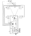
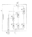
図1は、機密保護されたプレイアウト装置10が平文化鍵と共に暗号化されたオーディオデータ/ビデオマテリアルを受け取るデジタルシネマ構成を図式的に示している。平文化器20は、オーディオ及びビデオマテリアルを平文化する。平文化されたビデオマテリアルは、映写機30に供給され、スクリーン40に映写される。平文化されたオーディオマテリアルは、フィンガプリントエンコーダ50に供給され、フィンガプリントエンコーダ50は、上述のように、オーディオマテリアルにフィンガプリントを付加する。
FIG. 1 schematically illustrates a digital cinema configuration in which a
一般的に、フィンガプリントは、マテリアル、映画館及び上映日時のそれぞれについて一意的であってもよい。これにより、剽窃行為が行われたフィルムを特定することができる。 In general, a fingerprint may be unique for each of material, movie theater, and screening date. Thereby, the film on which plagiarism was performed can be specified.
フィンガプリントが付与されたオーディオ信号は、増幅器60に供給され、増幅器60は、周知の映画館の音響構成に基づいて、複数のスピーカ70及びサブウーファー80を駆動する。
The audio signal to which the fingerprint is applied is supplied to an
また、フィンガプリンティングは、映像情報にも適用できる。この場合、周知の映像用フィンガプリント付与装置(図示せず)を用いることができる。 Fingerprinting can also be applied to video information. In this case, a well-known image fingerprint applying device (not shown) can be used.
プレイアウト装置10は、好ましくは、機密保護され、外部接続がない閉じられたユニットであり、すなわち、フィンガプリントが付与されていないオーディオ(又は、実際にはビデオ)情報を外部から入手することができないように構成される。もちろん増幅器60及び映写機30は、機密保護されたシステムの一部を構成しなくてもよい。
The
上映された映画から不正コピーが作成された場合、例えば、映画館内でカムコーダを使用してコピーが撮影された場合、映画のフィルムに関連するオーディオコンテンツには、フィンガプリントエンコーダ50が符号化したフィンガプリント情報が含まれている。調査又は法的な理由から、このフィンガプリントを検出するためには、図2に示すフィンガプリント検出器80に、オリジナル(又は「プロキシ」)マテリアルと、オリジナルのフィンガプリントを生成するために用いられた鍵と共に、検査すべきマテリアルのコピーが供給される。単純に言えば、フィンガプリント検出器80は、被検査マテリアルに特定のフィンガプリントが存在している確率を算出する。検出処理については、後に更に詳細に説明する。
When an illegal copy is created from a movie that has been screened, for example, when a copy is taken using a camcorder in a movie theater, the fingerprint content encoded by the
埋込プロセス
ビデオフィンガプリンティングでは、この技術は、通常、フレーム単位で適用され(フレームは、ビデオ領域における自然な処理ブロックサイズである)、フィンガプリントペイロードベクトルの全体は、(低レベルで)各フレームに埋め込まれる。幾つかのシステムでは、フィンガプリントの強度は、フレームが「より混んでいる(busier)」画像領域において、又はビデオコンテンツの性質を大幅に変化させることなく取り除くことが困難又は不可能な下側の空間周波数が低い領域において、高く設定される。この手法では、単一のベクトルに関して相関を行っているかのように、多くのフレームに亘って、各フレームの相関を累積し、被検査ペイロードPsと、候補ペイロードPとの間に実際に統計的相関があれば、相関性は、フレーム毎に高くなっていく。
Embedding Process In video fingerprinting, this technique is usually applied on a frame-by-frame basis (the frame is the natural processing block size in the video domain), and the entire fingerprint payload vector is at each frame (at a low level). Embedded in. In some systems, the strength of the fingerprint may be difficult or impossible to remove in image areas where the frame is “busier” or without significantly changing the nature of the video content. It is set high in a region where the spatial frequency is low. In this approach, the correlations of each frame are accumulated over many frames as if they were correlated with respect to a single vector, and are actually statistically measured between the inspected payload Ps and the candidate payload P. If there is a correlation, the correlation increases for each frame.
オーディオの場合、通常、このような自然な処理ブロックが存在しない。 For audio, there is usually no such natural processing block.
この実施の形態では、高速フーリエ変換(fast Fourier transform:FFT)処理の効率を高めるために、オーディオのバージョンの処理ブロックサイズを、2の累乗個のオーディオサンプル、例えば、64kサンプル(65536のサンプル)に設定する。なお、ベクトル長は、処理ブロックと同じサイズになる。 In this embodiment, to increase the efficiency of the fast Fourier transform (FFT) processing, the processing block size of the audio version is set to a power of 2 audio samples, eg, 64k samples (65536 samples). Set to. The vector length is the same size as the processing block.
これらのオーディオフレームに関する連続した相関は、ビデオシステムの場合と同様に累積することができる。 Successive correlations for these audio frames can be accumulated as in a video system.
コンテンツの各サンプルについて、ペイロードベクトルの1つのサンプルが存在する。また、高周波数成分(例えば、5kHzより高い)及び低周波数成分(例えば、150Hz未満)は、いずれも、完全に削除しても音質に著しい影響がないため、ペイロードは、「中間周波数」に集中的に埋め込まれる。上述のような高い周波数帯域及び低い周波数帯域は、低品質な記録装置又は侵害者側の技術の影響で欠落してしまうこともあり、又はフィンガプリントの復元処理を妨害するために、侵害者が故意にこれらを取り除くこともある。したがって、主観的により重要な中間周波数、すなわち取り除いてしまうと音質が著しく劣化してしまう周波数帯域にペイロードを集中させることが適切である。 For each sample of content, there is one sample of the payload vector. Also, the high-frequency component (for example, higher than 5 kHz) and the low-frequency component (for example, less than 150 Hz) have no significant effect on sound quality even if they are completely deleted, so the payload is concentrated on the “intermediate frequency” Embedded. The high frequency band and the low frequency band as described above may be lost due to the low quality recording device or the technology of the infringer side, or the infringer may not be able to prevent the fingerprint restoration process. Sometimes they are deliberately removed. Therefore, it is appropriate to concentrate the payload on a subjectively more important intermediate frequency, that is, a frequency band in which the sound quality is significantly degraded if removed.
以下、埋込処理の概要を示す。
1.ペイロードをシードとして、AESラインダール疑似乱数ストリームに基づき、雑音ストリームを生成する。
2.オーディオストリームの知覚的解析に基づいて、雑音ストリームを「シェーピング」する。
3.シェーピングされた雑音ストリームを低レベルでオーディオストリームに付加する。
The outline of the embedding process is shown below.
1. A noise stream is generated based on the AES line Dahl pseudorandom number stream using the payload as a seed.
2. Based on the perceptual analysis of the audio stream, the noise stream is “shaped”.
3. Append the shaped noise stream to the audio stream at a low level.
生成された雑音ストリームは、ペイロードデータの異なるサブセットからそれぞれ生成された複数のレイヤをストリーム内に含む。なお、例えば、フレーム番号及び/又は日付/時間等の他のデータをペイロードに含ませてもよい。 The generated noise stream includes multiple layers, each generated from a different subset of payload data, in the stream. For example, other data such as a frame number and / or date / time may be included in the payload.
雑音ストリームは、移動カウンタに256ビットのラインダール暗号化を繰り返し適用することによって生成される。そして、この数を±1.0の範囲内に換算し、フルスケールの白色雑音を生成する。白色雑音ストリームは、複数の点の対にボックスミューラー変換を適用することによってガウス雑音に変換される。 The noise stream is generated by repeatedly applying 256 bits of line-dahl encryption to the movement counter. Then, this number is converted into a range of ± 1.0 to generate full-scale white noise. The white noise stream is converted to Gaussian noise by applying a box Mueller transform to the pairs of points.
この実施の形態では、雑音ストリームには、16のレイヤがある。疑似ランダム雑音発生器の第1のレイヤは、ペイロードの最初の16ビットによってシードされ、第2のレイヤは、ペイロードの最初の32ビットによってシードされ、以下同様の処理により、第16のレイヤは、全体の256ビットペイロードによってシードされる。 In this embodiment, there are 16 layers in the noise stream. The first layer of the pseudo-random noise generator is seeded by the first 16 bits of the payload, the second layer is seeded by the first 32 bits of the payload, and so on, by a similar process, the sixteenth layer is Seeded by the entire 256-bit payload.
知覚的解析は、オーディオストリームの各サンプルについて、フィンガプリント雑音ストリームを換算するための利得値を算出する単純なスペクトル解析を含む。ここでは、音量が大きいオーディオストリームのセクションは、より強いフィンガプリント雑音を隠すことができるという点を利用している。 Perceptual analysis includes a simple spectral analysis that calculates a gain value for converting the fingerprint noise stream for each sample of the audio stream. Here, we take advantage of the fact that sections of an audio stream with a high volume can hide stronger fingerprint noise.
この概念の拡張として、オーディオストリームの中間周波数成分(フィンガプリントを隠す帯域)を幾つか(例えば、8又は12)の帯域に分割してもよく、これらの帯域は、対数による周波数スケールに関して均等に分割することが好ましい(もちろん如何なる手法で帯域を分割してもよい)。これは、例えば、周波数スペクトルを概ねオクターブ毎に分割することを意味する。そして、各帯域を個別に処理して、それぞれの利得エンベロープを生成し、これを用いて、フィンガプリント雑音ストリーム内における対応する周波数帯域の振幅を調節する。全ての帯域でエンベロープ変調を用いると、雑音ストリームは、元のオーディオデータ信号の「ゴースト」を再生しているかのように聞こえる。より重要な点は、成分が類似しているためにゴーストのように聞こえる雑音ストリームを元のマテリアルに加えると、比較的高い信号レベルにおいて加算を行っても、人間の耳には聞こえなくなるという点である。例えば、変調された雑音を、オーディオに対して−30dB(デシベル)程度の高いレベルで加算しても、主観的には殆ど聞き取られない。 As an extension of this concept, the intermediate frequency components (bands that hide the fingerprint) of the audio stream may be divided into several (eg, 8 or 12) bands, which are equally distributed with respect to the logarithmic frequency scale. It is preferable to divide the band (of course, the band may be divided by any method). This means, for example, that the frequency spectrum is divided approximately every octave. Each band is then processed individually to generate a respective gain envelope that is used to adjust the amplitude of the corresponding frequency band in the fingerprint noise stream. With envelope modulation in all bands, the noise stream sounds as if it were reproducing the “ghost” of the original audio data signal. More importantly, if you add a noise stream that sounds like a ghost because the components are similar to the original material, it will not be audible to the human ear, even if you add at a relatively high signal level. It is. For example, even if the modulated noise is added to the audio at a high level of about −30 dB (decibel), it is hardly heard subjectively.
この実施の形態では、2049サンプルのインパルス応答カーネルを用いて、「レンガ壁(ブリックウォール)」(側辺が急峻な応答)畳込み帯域フィルタを実現し、各周波数帯域における情報を分離する。畳込みは、処理速度のために、FFT領域で実行される。バンドパスフィルタとして、再帰形フィルタではなく畳込みフィルタを用いる1つの重要な理由は、畳込みフィルタでは、周波数から独立した固定された遅延を有するように構成できるためである。この点が重要である理由は、如何なる任意の周波数帯域に対する雑音ストリームの変調についても、雑音ストリームが付加されたとき、雑音ストリームが元のコンテンツの実際のエンベロープに追従するようにしなければならないためである。フィルタの遅延が周波数に依存していれば、このために生じるアラインメント誤差の修正は困難であり、雑音が目立つようになり、周波数の相関値が変化してしまう可能性もある。 In this embodiment, a “brick wall” (a response with a steep side) convolution band-pass filter is realized by using an impulse response kernel of 2049 samples, and information in each frequency band is separated. Convolution is performed in the FFT domain for processing speed. One important reason for using convolutional filters rather than recursive filters as bandpass filters is that convolutional filters can be configured to have a fixed delay independent of frequency. This is important because for any modulation of the noise stream for any frequency band, when the noise stream is added, the noise stream must follow the actual envelope of the original content. is there. If the delay of the filter depends on the frequency, it is difficult to correct the alignment error caused by this, noise becomes conspicuous, and the correlation value of the frequency may change.
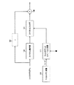
図1のエンコーダ50等のフィンガプリントエンコーダの動作の概略について図3を用いて説明する。ペイロード生成器100は、フィンガプリントとして符号化されるペイロードデータを生成する。上述のように、ペイロードデータは、様々なコンテンツ及び他の識別子を含むことがあり、更にコンテンツの再生毎に固有である場合がある。ペイロード生成器については、図4を参照して、後に詳細に説明する。
An outline of the operation of a fingerprint encoder such as the
ペイロードは、フィンガプリントストリーム生成器110に供給される。フィンガプリントストリーム生成器110は、上述したように、基本的に、AES−ラインダール暗号化を用いる乱数発生器であり、暗号鍵に基づいて、ペイロード生成器100から供給されたペイロードに応じて出力シーケンスを生成する。フィンガプリントストリーム生成器については、図5を参照して、後に詳細に説明する。
The payload is supplied to the
ソースマテリアル(フィンガプリントが適用される)は、スペクトル解析器120に供給される。スペクトル解析器120は、1つ以上の周波数帯域において、ソースマテリアルの振幅又はエンベロープを解析する。スペクトル解析器120は、スペクトルフォロワ130にエンベロープ情報を供給する。スペクトルフォロワ130は、スペクトル解析器120からのエンベロープ情報に基づいて、フィンガプリントストリーム生成器110から出力された雑音信号を変調する。スペクトル解析器120については、図6を参照して後に詳細に説明し、スペクトルフォロワ130については、図7を参照して後に詳細に説明する。
The source material (to which the fingerprint is applied) is supplied to the
スペクトルフォロワ130の出力は、ソースマテリアルに比べてかなりレベルが低いが、ソースマテリアルのエンベロープに概ね追従する雑音信号である。雑音信号は、加算器140によってソースマテリアルに加算される。これにより、加算器140は、フィンガプリントが付与されたオーディオ信号を出力する。
The output of the
図3では、ソースマテリアルパスに、遅延要素150を示している。これは、加算器140に供給されるバージョンに比べて時間的に進んだソースマテリアルのバージョンに関してスペクトル解析及びエンベロープ判定が実行されることを示している。この時間的な進みに関しては、後に更に詳細に説明する。
In FIG. 3, a
図4は、ペイロード生成器100の構成を示している。上述のように、ペイロード生成器100は、シリアル番号、位置識別子、位置秘密鍵等の様々な識別情報に基づいて、ペイロードデータ160を生成し、フィンガプリントストリーム生成器110にペイロードデータ160をシードとして供給する。暗号化器170は、位置秘密鍵を用いて、位置識別子を暗号化する。ロジック180は、ペイロードデータの様々なコンポーネントをビット整列させ、シードとして出力する。
FIG. 4 shows the configuration of the
図5は、フィンガプリントストリーム生成器110の構成を示している。フィンガプリントストリーム生成器110は、ペイロード生成器100からシードデータ160を受け取り、鍵データ190は、鍵拡大ロジック200によって、16個の異なる鍵K−1〜K−16に拡大される。
FIG. 5 shows the configuration of the
オプションとして、加算器210によって、シードデータ160にフレーム番号を加えてもよい。
Optionally, the
フィンガプリントストリーム生成器110は、16個のAES−ラインダール数発生器220〜236を備える。各AES−ラインダール数発生器220〜236には、鍵拡大ロジック200からそれぞれの鍵が供給される。更に、各AES−ラインダール数発生器220〜236には、シードデータ160からそれぞれのビットの組がシードされる。例えば、AES−ラインダール数発生器220には、シードデータ160の最初の16ビットがシードされる。AES−ラインダール数発生器221には、シードデータ160の最初の32ビットがシードされる。この構成により、ペイロードを階層化することができ、これにより、まず、最初の16ビットについて可能な全ての値を検索し、次に、17番目から32番目のビットの可能な値(最初の16ビットは既知)を検索する等により、復号時に特定のフィンガプリントを検索する処理が容易になる。
The
各AES−ラインダール数発生器220〜236から出力されるデータは、それぞれガウスマッピング回路(Gaussian mapping arrangement)240〜256に供給される。ガウスマッピング回路240〜256は、実際には白色雑音となる乱数を生成する乱数数発生器であり、既知のマッピングプロセスを用いてガウス関数形プロファイルの雑音を生成する。
Data output from each AES-Line Dahl number generator 220-236 is supplied to Gaussian mapping circuits 240-256, respectively.
加算器260は、ガウスマッピング回路240〜256の各インスタンスからのガウス雑音信号を加算し、雑音信号270を生成し、出力する。
The
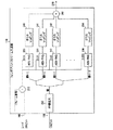
図6は、スペクトル解析器120の構成を示している。スペクトル解析器120は、入力データとしてソースマテリアル(フィンガプリントが付与される)を受け取り、出力データとしてエンベロープ情報280を生成する。
FIG. 6 shows the configuration of the
スペクトル解析器120は、(この具体例では)8個の帯域フィルタ290〜297の組を備え、各帯域フィルタ290〜297は、ソースマテリアルのそれぞれの周波数帯域をフィルタリングする。フィルタの周波数帯域は、重なっていても重なっていなくてもよく、8個のフィルタによってカバーされる全体の使用可能な周波数範囲は、100パーセントであってもよく、多くの場合そうであるように、100パーセントに満たなくてもよい。8個の各フィルタに関連するそれぞれの周波数帯域は、連続していてもよく(すなわち、互いに隣接していてもよく)、連続していなくてもよい。使用するフィルタ(周波数帯域)の数は、8個より多くても少なくてもよい。すなわち、ここでの記述は、単に、フィルタの動作に関する1つの具体例を説明しているに過ぎない。
The
この具体例では、中間の周波数範囲は、約150Hzから約5kHzまでのフィルタによって処理される。この範囲は、対数的に均等な8個の帯域に分割され、したがって、各帯域は、約1オクターブに相当する。帯域フィルタ290〜297で用いられるフィルタリング技術は、上述した通りである。
In this example, the intermediate frequency range is processed by a filter from about 150 Hz to about 5 kHz. This range is divided into 8 logarithmically equal bands, so each band corresponds to about one octave. The filtering technique used in the band-
各帯域フィルタ290〜297の出力側には、検波器(エンベロープ検出器)300〜307が接続されている。検波器300〜307は、各帯域フィルタの出力信号について、フィルタリングされたソースマテリアルのエンベロープに関連するエンベロープ信号を生成する。 Detectors (envelope detectors) 300 to 307 are connected to the output sides of the band filters 290 to 297. Detectors 300-307 generate, for each bandpass filter output signal, an envelope signal associated with the filtered source material envelope.
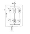
図7は、スペクトルフォロワ130の構成を示している。スペクトルフォロワ130には、スペクトル解析器120からエンベロープ情報280が供給され、フィンガプリントストリーム生成器110からガウス雑音信号270が供給される。
FIG. 7 shows the configuration of the
ガウス雑音信号270は、一組の帯域フィルタ310〜317に供給される。帯域フィルタ310〜317の応答は、スペクトル解析器120の対応する帯域フィルタ290〜297の応答と同様に(又は実質的に同等に)設定されている。帯域フィルタ310〜317は、雑音スペクトル内の8個の帯域を生成する。フィルタリングされた各雑音帯域は、それぞれのエンベロープフォロワ320〜327に供給される。エンベロープフォロワ320〜327は、ソースマテリアルにおける対応する帯域のエンベロープに関するエンベロープ信号に基づいて、同じ帯域のフィルタリングされた雑音信号を変調する。加算器330は、エンベロープフォロワ320〜327の全ての出力を加算し、シェーピングされた雑音信号340を生成する。
The
エンベロープフォロワ320〜327は、最終的にシェーピングされた雑音信号340がソースマテリアルに対して適正なレベル、例えば、ソースマテリアルの−30dBとなるようにするための換算回路を備えていてもよい。
The
上述のように、加算器140は、シェーピングされた雑音信号340をソースマテリアルに加算し、フィンガプリントが付与されたソースマテリアルを出力信号として生成する。
As described above, the
フィンガプリントの付与は、異なるオーディオチャンネルに関して(左右のチャンネル等)個別に行ってもよく、同期させて行ってもよい。なお、侵害者が複数のチャンネルを比較することによってフィンガプリントを推定する(及び除去又は無効にする)ことを防止するために各チャンネルについて異なる雑音信号を用いることが好ましい。いずれの場合も、エンベロープ信号280は、好ましくは、符号化されたフィンガプリントである個々のオーディオチャンネルに関連する。
Fingerprints may be assigned individually for different audio channels (such as left and right channels) or may be synchronized. Note that it is preferable to use a different noise signal for each channel to prevent an infringer from estimating (and removing or invalidating) the fingerprint by comparing multiple channels. In any case,
以下、上述したエンベロープ検出及びエンベロープ追従の動作について、図8〜図11を用いて説明する。なお、上述したスペクトルフォロワの場合、エンベロープ追従は、それぞれのチャンネル又は帯域に関して実行される。また、以下に説明する時定数は、帯域に適用可能な可聴周波数又は周波数範囲に基づいて、例えば、その帯域内の信号の最速の立上がり時間に基づいて設定することができる。これによって、単に時定数と最速の立上がり時間との間の関係を変更するだけで、時定数をグループとして調整することができる。 Hereinafter, the above-described envelope detection and envelope following operations will be described with reference to FIGS. In the case of the spectral follower described above, envelope tracking is performed for each channel or band. Also, the time constant described below can be set based on the audible frequency or frequency range applicable to the band, for example, based on the fastest rise time of the signal in the band. This allows the time constants to be adjusted as a group simply by changing the relationship between the time constant and the fastest rise time.
図8〜図11において、横軸は、任意のスケールの時間を表し、実線は、ソースマテリアルに関連するエンベロープ信号の具体例を(概略的に)表し、破線は、エンベロープフォロワ320〜327が適用した変調を(概略的に)表している。
8 to 11, the horizontal axis represents time of an arbitrary scale, the solid line represents a specific example of the envelope signal related to the source material (schematically), and the broken line represents the
図8では、エンベロープフォロワが時定数を適用し、ソースマテリアルのエンベロープの急激な上昇に応じた雑音信号の立上がり時間を制限している。これは、実線の垂直的な上昇の後ろで時間的に遅れた破線の左側のセクションによって表されている。このような時定数は、「アタック」時定数とも呼ばれる。なお、図8〜図11において、雑音信号の上昇のレートは、制限されているが、雑音信号が上昇を開始する時刻は、エンベロープ信号が上昇し始める時刻と同じである(検出遅延によって生じる僅かな時間差はある)。エンベロープ信号に対して、雑音信号の上昇の開始を遅延させてもよい(又は後述する時間的に進める構成では、進めてもよい)が、これによる利益は殆どない。具体的には、雑音信号の上昇を遅らせると、上昇する信号に隠すことができる有用なペイロードが制限され、雑音信号の上昇の開始を進めると、図8のエンベロープのトレーリングエッジに関して説明するものと同様の可聴雑音が生じる可能性がある。 In FIG. 8, the envelope follower applies a time constant to limit the rise time of the noise signal in response to a sudden rise in the envelope of the source material. This is represented by the dashed left-hand section delayed in time behind the solid vertical rise. Such a time constant is also called an “attack” time constant. 8 to 11, the rate at which the noise signal rises is limited, but the time at which the noise signal starts to rise is the same as the time at which the envelope signal begins to rise (slightly caused by the detection delay). There is a significant time difference). Although the start of the rise of the noise signal may be delayed with respect to the envelope signal (or may be advanced in a configuration that advances in time described later), there is almost no benefit from this. Specifically, delaying the rise of the noise signal limits the useful payload that can be hidden by the rising signal, and proceeding with the start of the rise of the noise signal will explain the trailing edge of the envelope in FIG. The same audible noise may occur.
また、後半の破線によって示す、ソースマテリアルエンベロープのトレーリングエッジにおける雑音エンベロープの減少は、「ディケイ」時定数によって制限される。これは、t1からt2までの期間に亘って、雑音信号がソースマテリアル信号より大きく、したがって、聴取者にとって、雑音が主観的に邪魔に感じられる可能性があることを意味する。 Also, the reduction of the noise envelope at the trailing edge of the source material envelope, indicated by the dashed line in the second half, is limited by the “decay” time constant. This means that over the period from t 1 to t 2 , the noise signal is larger than the source material signal, and therefore the noise can be perceived subjectively by the listener.
図9は、エンベロープに追従するオーディオ効果プロセッサに共通の状況を示しており、エンベロープ追従信号(この場合、雑音信号)のディケイが開始するまでの時間として定義される「サステイン」期間350を示している。これによって、上述した状況が更に悪くなり、すなわち、雑音信号は、時刻t1からt3までの期間に亘ってソースマテリアル信号より大きくなる。このため、この実施の形態では、サステイン期間を用いない。
FIG. 9 illustrates a situation common to audio effects processors that follow an envelope, showing a “sustain”
この問題を解決する手法について、図10及び図11を用いて説明する。 A method for solving this problem will be described with reference to FIGS.
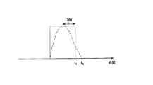
図10では、雑音信号が減少し始める時刻は、ソースマテリアルのエンベロープが減少する時刻より、進み時間(advanced time)360だけ進められている。この具体例では、これは、雑音信号が、時刻t1までに、無視できる程度のレベルにまで減少することを意味する。
In FIG. 10, the time at which the noise signal begins to decrease is advanced by an
一方、図11に示すように、進み時間360を少し短くすると、雑音信号は、ソースマテリアルのエンベロープが減少する前に減少し始めるが、時刻t1までに、十分に減少しない。これは、時刻t1からt4までの間に少量の雑音が残ることが意味するが、図8に示す状況に比べれば、雑音は軽減されている。
On the other hand, as shown in FIG. 11, when the
このように、雑音低減を促すソースマテリアルエンベロープの減少より前に雑音信号の減少を開始することによって、図8及び図9に示すような主観的に邪魔になる過剰な雑音を軽減又は除去することができる。 Thus, reducing or eliminating excessive noise that is subjectively disturbing as shown in FIGS. 8 and 9 by starting to reduce the noise signal before reducing the source material envelope that promotes noise reduction. Can do.
これを実現するためには、加算器140によってソースマテリアルに雑音を加算するより前に、ソースマテリアルのエンベロープ情報を取得することができるようにシステム内のどこかに遅延回路を含ませる必要がある。図3に示す遅延要素は、この遅延の具体例を概略的に示している。この他の多くの可能性があることは、当業者にとって明らかである。上述の具体例では、ソースマテリアルから結合器140までのパスに遅延要素が設けられている。この構成では、スペクトル解析器120は(各エンベロープ信号に関して、1つ以上が導出される場合)、以下のように動作する。(a)上昇するエンベロープについては、(図示しない遅延要素によって)遅延要素が適用する遅延τに同等な遅延をエンベロープ信号に適用する。(b)下降するエンベロープについては、遅延τより小さい遅延をエンベロープ信号に適用する。
To achieve this, it is necessary to include a delay circuit somewhere in the system so that the envelope information of the source material can be acquired before adding noise to the source material by the
抽出処理
フィンガプリント抽出の主な処理手順は以下の通りである。
1.被検査マテリアルを処理し、全ての破損又は歪みを元に戻すことを試みる。
2.所謂プロキシコンテンツ(ウォータマークが付されていない元のバージョンのコンテンツを示す用語)を被検査コンテンツから減算し、この差として、被検査フィンガプリントを算出する。この処理では、被検査マテリアルとプロキシコンテンツとを時間的に整列する必要がある。幾つかの具体例では、ウォータマークが付されたプロキシを用いてもよい。もちろん、プロキシのウォータマークは、相関によって検出されるが、他のウォータマークの検出を妨害せず、無視することができる。この手法によって、抽出処理を委託したサードパーティに、機密保護されたコピーを供給することができる。
3.被検査フィンガプリントを、プロキシコンテンツのスペクトル解析に基づいて「逆シェーピングする(unshaped)」。
4.このコンテンツの母集団における各候補ペイロードについて、コンテンツの比較的短いセクションに亘って、候補ペイロードを被検査ペイロードと比較する。値SimValが有望である場合、この候補を候補の候補リストに加え、更に長い解析を行う。
Extraction Processing The main processing procedure for fingerprint extraction is as follows.
1. Process the material under test and attempt to undo any damage or distortion.
2. So-called proxy content (a term indicating the original version of content without a watermark) is subtracted from the inspected content, and the inspected fingerprint is calculated as the difference. In this process, it is necessary to align the material to be inspected and the proxy content in time. In some implementations, a proxy with a watermark may be used. Of course, the proxy watermark is detected by correlation, but does not interfere with the detection of other watermarks and can be ignored. This approach allows a secure copy to be supplied to a third party that has commissioned the extraction process.
3. The inspected fingerprint is “unshaped” based on a spectral analysis of the proxy content.
4). For each candidate payload in this content population, the candidate payload is compared to the inspected payload over a relatively short section of content. If the value SimVal is promising, add this candidate to the candidate candidate list and perform a longer analysis.
図2の検出器80等のフィンガプリント検出器の動作について、図12を用いて説明する。検出器には、例えば、海賊版コピーの疑いがあるコンテンツのピースである被検査マテリアルと、所謂プロキシマテリアルのプレーンな(ウォータマークが付されていない)コピーとが供給される。
The operation of a fingerprint detector such as the
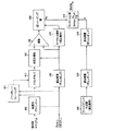
被検査マテリアルは、まず、時間的アラインメントユニット400に供給される。時間的アラインメントユニット400の動作については、図13〜図18を用いて後述する。簡潔に言えば、時間的アラインメントユニット400は、プロキシマテリアルと被検査マテリアルの間の時間的なオフセットを検出し、これによって、2つのマテリアルを時間的に整列させる。時間的アラインメントユニット400によって潜在的に実現できる整列は、ある許容誤差範囲内、例えば、±1サンプル内に収められる。更に、2つの信号間で完全な整列を実現するための時間補正が後述するデコンボルバ(deconvolver)410によって実行される。
The material to be inspected is first supplied to the
デコンボルバ410は、被検査マテリアルにインパルス応答を適用し、プロキシマテリアルに更に近くなるように試みる。ここでの目的は、被検査マテリアルにおける信号劣化による変化を(少なくとも部分的に)逆に戻すことである。このような劣化の具体例については、後に列挙する。
The
このために、デコンボルバ410は、デコンボルバトレーニングユニット420によって「トレーニングされる」。デコンボルバトレーニングユニット420の動作については、図19〜図25を用いて後に詳細に説明するが、簡潔に言えば、デコンボルバトレーニングユニット420は、時間的に整列された被検査マテリアルとプロキシマテリアルとを比較し、プロキシマテリアルから被検査マテリアルへの差分を表す変換応答を導出する。デコンボルバ410は、この変換応答の「逆」を適用する。変換応答は、特定の位置に生じた劣化を反映するために、好ましくは、被検査マテリアル内の異なる位置毎に更新される。以下で説明する実施の形態では、デコンボルバトレーニングユニット420は、被検査マテリアル及びプロキシマテリアルのブロックについて、最新の部分の所定のグループに亘って検出された応答の移動平均に基づいて、変換応答を検出する。
To this end, the
遅延補償回路430は、デコンボルバ410及びデコンボルバトレーニングユニット420における処理の遅延を補償する。
The
次に、相互正規化ユニット440は、デコンボルブされた被検査マテリアルとプロキシマテリアルの振幅を正規化する。図12に示す具体例では、正規化は、被検査マテリアルに対して行われているが、ここで、プロキシマテリアルの振幅を調整してもよく、又は両方の振幅を調整してもよいことは明らかである。
Next, the
正規化の後、減算器450は、デコンボルブされ、正規化された被検査マテリアルとプロキシマテリアルとの間の差を算出する。この差を表す信号は、「逆シェーピング器(unshaper)」460に供給され、逆シェーピング器460は、スペクトルフォロワ130によって実行されたノイズシェイピング処理の逆の処理を実行する。このために、プロキシマテリアルは、図3のスペクトル解析器120と同様に動作するスペクトル解析器470に供給される。
After normalization, the
このように、スペクトル解析器470及び逆シェーピング器460は、逆シェーピング器460の出力として包括的に均一な雑音エンベロープを生成する目的でエンベロープ制御された利得値の逆数を用いる点を除いて、スペクトル解析器120及びスペクトルフォロワ130と同様に動作する。逆シェーピング器460によって生成された雑音信号Psは、比較器480に供給される。比較器480へ他方の入力であるPは、以下のように生成される。
Thus, the
フィンガプリント生成器490は、図3のペイロード生成器100及びフィンガプリントストリーム生成器110と同様に動作する。したがって、これらの動作については詳細には説明しない。フィンガプリント生成器490は、被検査マテリアルに存在している可能性があるフィンガプリントの全ての可能なバリエーションを生成する。そして、各バリエーションを検査し、それぞれの尤度を表す値SimValを導出する。
もちろん、複数のフィンガプリント生成器490を採用し、並列に動作する複数の比較器480を用いて、雑音ストリームPsを一度に2つ以上のフィンガプリントと比較してもよい。
Of course, a plurality of
遅延補償器500、510は、被検査マテリアルに生じた処理遅延を補償し、フィンガプリント生成器490によって生成されたフィンガプリントと、フィンガプリント被検査マテリアル内に含まれている可能性があるフィンガプリントとを時間的に正しく揃える。
逆シェーピング器460による出力までの処理を繰り返すことなく、逆シェーピング器460の出力を保存し、異なるフィンガプリントのそれぞれについて、一回以上の更なる比較(モジュール490、500、510で実行される)を実行してもよい。
Save the output of the
時間的アラインメント
海賊版の疑いがある被検査信号に対しては、最初に行わなくてはならないのは、プロキシ信号との正しい同期である。
Temporal Alignment The first thing that must be done for an inspected signal that is suspected of being pirated is correct synchronization with the proxy signal.
必要であれば、再サンプリング又はMP3符号化の影響により生じた全てのサブサンプル遅延/進みを補償するために、サブサンプル遅延回路を設けてもよい。 If necessary, a subsample delay circuit may be provided to compensate for any subsample delay / advance caused by resampling or MP3 encoding effects.
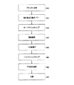
図13は、時間的アラインメントユニット400の動作の一部を示すフローチャートである。このフローチャートの各ステップは、時間的アラインメントユニット400の各部分又は機能によって実現される。
FIG. 13 is a flowchart showing a part of the operation of the
理論上は、(単一の)直接的な相関処理によって被検査マテリアルとプロキシマテリアルとを揃えることも可能であるが、演算処理は、一般的に、オーディオサンプル数の2乗に比例して増加するため、大きなマテリアル、例えば、映画のサウンドトラック等では、必要な相関処理が膨大になる。したがって、ここでの処理は、2つの信号を完全に相関させるのではなく、少なくとも大雑把に揃えることを目的とする。 Theoretically, it is possible to align the inspected material and the proxy material by a (single) direct correlation process, but the computation generally increases in proportion to the square of the number of audio samples. Therefore, a large amount of correlation processing is required for a large material, for example, a movie sound track. Therefore, the purpose of the processing here is not to completely correlate the two signals but to at least roughly align them.
図13のステップ600のにおいて、2つのオーディオ信号を複数の部分又はブロックに分割する。これらのブロックは、それぞれの2つの信号について、サイズが等しいが、このサイズは、特定のサイズである必要はない。このため、一具体例では、(例えば)サイズを64kサンプルとして固定してもよく、他の具体例では、ブロックの数を固定してもよく、これによりマテリアル(通常、プロキシマテリアル)の2つのピースの全長を所定のブロック数に従って分割し、時間的アラインメント処理のこの特定のインスタンスのために必要なブロックサイズを得る。如何なる場合も、ブロックサイズは、少なくとも2サンプルを含む必要がある。
In
図13のステップ600の前に、予備的なローパスフィルタリング処理(図示せず)を行ってもよい。これにより、ブロックサイズに関して、2つの信号の間の任意のアラインメント誤差によって生じる何らかのアーチファクトを削減することができる。 Prior to step 600 in FIG. 13, a preliminary low-pass filtering process (not shown) may be performed. This can reduce any artifacts caused by any alignment error between the two signals with respect to the block size.
ステップ605では、各信号の絶対値を算出し、各ブロックについて、(絶対値を参照して)検出された最大パワーを導出する。もちろん、これに代えて、例えば平均パワー等の異なるパワー特性を導出してもよい。ここでの目的は、プロキシ信号及び被検査信号のそれぞれから、1ブロックあたりの値の数が少ない(例えば、1個又は2個の)パワー特性信号を得ることである。この具体例では、1ブロックあたり1つの値がある。
In
ステップ610では、2つのパワー特性信号をローパスフィルタリング又は円滑化する。
In
図14は、2つの信号をブロックに分割する処理を図式的に示しており、この具体例では、プロキシマテリアルは、完全な長さの映画フィルムを表し、被検査マテリアルは、その映画フィルムから切り取られたセクションを表す。 FIG. 14 schematically illustrates the process of splitting two signals into blocks, in this example the proxy material represents a full length movie film and the material to be inspected is cut from the movie film. Represents the specified section.
図15は、2つのパワー特性信号に適用される個別のローパスフィルタを示している。各サンプルは、(乗算器611によって)係数に乗算され、加算器612において、加算器612の出力を第2の係数に乗算した積が加算される。この第2の係数の乗算は、乗算器613で行われる。この処理により、各信号のローパスフィルタリングされたバージョンが生成される。
FIG. 15 shows separate low-pass filters applied to two power characteristic signals. Each sample is multiplied by a coefficient (by multiplier 611), and
この時点で、2つのパワー特性信号は、通常、0と1の間の振幅を有する。フィルタリング処理によって、1以上の小さな偏差が生じることがあるが、ステップ605における絶対値検出のために、0より小さい偏差が生じることはない。
At this point, the two power characteristic signals typically have an amplitude between 0 and 1. Although the filtering process may cause a small deviation of 1 or more, a deviation smaller than 0 is not caused due to the absolute value detection in
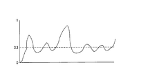
ステップ630では、閾値を適用する。この処理を図16に図式的に示す。このような閾値の具体例は、0.3であるが、他の如何なる値を用いてもよい。
In
閾値は、以下のように適用される。 The threshold is applied as follows.
ここでの目的は、閾値に対応するパワー特性信号値を修正された値の1つにマッピングすることである。閾値以下の全ての信号値は、0と1の間の信号値にマッピングされる。閾値を超える全ての信号値は、1以上の信号値にマッピングされる。したがって、この処理を実現する単純な手法は、全体のパワー特性信号を1/閾値の値、この場合、3.33・・・に乗算することである。 The purpose here is to map the power characteristic signal value corresponding to the threshold value to one of the modified values. All signal values below the threshold are mapped to signal values between 0 and 1. All signal values that exceed the threshold are mapped to one or more signal values. Therefore, a simple technique for realizing this process is to multiply the entire power characteristic signal by 1 / threshold value, in this case 3.33.
これが適切である理由は、次のステップ640において、信号にべき乗を適用するためである。この具体例では、各信号を2乗し、すなわち、各サンプル値をそのサンプル値自体の値に乗算する。但し、2以上の乗数として、整数又は非整数を用いてもよい。ステップ630及びステップ640によって、より高い信号値が強調され、下側の信号値の効果が減少する。これは、0と1の間の如何なる信号数も1より大きなベキ指数で累乗されると(例えば、2乗されると)、より小さくなり、1より大きな信号値は、1より大きなベキ指数で累乗されると大きくなるためである。
The reason this is appropriate is to apply a power to the signal in the
べき乗を行った後、ステップ650において、べき乗された信号に対し、オプションのハイパスフィルタリング処理を行う。ステップ660において、各信号の平均値を減算し、ゼロ平均の信号を生成する(このステップにより、以下の相関ステップ670における処理が好適に行われる)。
After powering, in
最後に、ステップ670において、パワー特性信号を相関処理する。この処理では、図17に図式的に示すように、被検査マテリアルからのパワー値をゼロでパディングし、プロキシマテリアルと同じ長さのデータ集合を提供するによって実行される。相関処理は、(望ましくは)ピーク相関を生成し、このピーク位置の中心位置702からのオフセット701は、2個のファイルの間の時間的なオフセットを示す。このオフセットは、プロキシ又は被検査信号のいずれかに相対的な遅延を適用することによって補正できる。
Finally, in
図13〜図17を参照して説明した処理は、(第1の処理から、オフセット701を開始位置及び概算値とし選択することによって)より小さいブロックサイズ及び相関が実行されたより狭い範囲に対して繰り返すことができる。もちろん、ブロックサイズを適切に小さくしながら、処理を2回以上繰り返してもよい。処理の利益を得るためには、ブロックサイズは、少なくとも2つのサンプルを含む必要がある。 The process described with reference to FIGS. 13-17 is for a smaller block size and a smaller range over which correlation has been performed (from the first process, by selecting offset 701 as the starting position and approximate value). Can be repeated. Of course, the processing may be repeated twice or more while appropriately reducing the block size. To obtain processing benefits, the block size needs to include at least two samples.
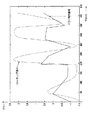
図18は、ステップ605によって生成されたパワー特性信号及びステップ660によって生成されたフィルタリングされたパワー特性信号を図式的に示している。ここでは、閾値は0.3であり、ステップ640におけるベキ指数は1.5であり、1/10の換算を行っている。
FIG. 18 schematically shows the power characteristic signal generated by
破損の回復
破損回復の目的は、海賊版のコンテンツがオリジナルのプロキシバージョンに可能な限り近付くように、海賊版のコンテンツを変換することである。これにより、海賊版からプロキシを減算して算出された被検査ペイロードPsが可能な限り小さくなり、この結果、SimValの値は、通常、より大きくなる。
Corruption Recovery The purpose of corruption recovery is to convert pirated content so that the pirated content is as close as possible to the original proxy version. Thereby, the inspected payload Ps calculated by subtracting the proxy from the pirated version becomes as small as possible, and as a result, the value of SimVal usually becomes larger.
オーディオ信号の場合、以下に列挙するような、偶然に生じた、又は侵害者によって故意に施された様々な歪みの可能性があり、いずれの場合も、これらの歪みによってSimVal値が小さくなる。
*高域、低域、ノッチ、帯域又はパラメトリックフィルタリング
*圧縮、拡張、リミッティング、ゲーティング
*オーバードライブ、クリッピング
*インフレーション、バルブ音及びこの他の音強調効果
*再サンプリング、A/D変換及びD/A再変換
*周波数ドリフト、ワウ及びフラッタ、位相反転、バリスピード
*MP3及びこれに類する不可逆符号化/復号技術
*エコー、リバーブ、空間音像定位
*所謂ディエッシング(de-essing)、ディヒッシング(de-hissing)、ディクラッキング(de-crackling)
これらの破損をできるだけ多く回復するために、フィンガプリント回復構成は、汎用のデコンボルバを備え、デコンボルバは、プロキシ信号に関してトレーニングされ、畳込みフィルタの動作によって生成されたあらゆる作用を大幅に低減又は除去する。デコンボルバの使用例は、電気通信(システム内の多くの異なるパスを通過する信号に課される望ましくないエコーを除去する。)及び保存されたマテリアルの復元プロジェクト(経年劣化を除去し、又は記録設備の性能の悪さから生じたアーチファクトを除去する。)等がある。
In the case of audio signals, there may be various distortions that may have occurred by chance or deliberately applied by the infringer, as listed below, and in any case, these distortions will reduce the SimVal value.
* High, low, notch, band or parametric filtering * Compression, expansion, limiting, gating * Overdrive, clipping * Inflation, valve sound and other sound enhancement effects * Resampling, A / D conversion and D / A re-conversion * frequency drift, wow and flutter, phase inversion, variable speed * MP3 and similar irreversible encoding / decoding technology * echo, reverb, spatial sound localization * so-called de-essing, de-hishing hissing), de-crackling
In order to recover as much as possible of these corruptions, the fingerprint recovery configuration includes a general purpose deconvolver that is trained on the proxy signal to significantly reduce or eliminate any effects generated by the operation of the convolution filter. . Examples of deconvolver use are telecommunications (removing unwanted echoes imposed on signals passing through many different paths in the system) and stored material restoration projects (removing aging or recording equipment) To remove artifacts resulting from poor performance.
簡潔に言えば、デコンボルバは、海賊版の疑いがある被検査オーディオマテリアル及び代理バージョンをFFT領域に変換することによってトレーニングされる。ここでは、所望の信号(プロキシ)の現実/仮想値を、実際の信号(海賊版)の現実/仮想値で除算(複素除算)し、実際の応答を所望の応答に変換するインパルス応答カーネルのFFTを得る。これにより得られたFFTを円滑化し、先のインスタンスとの平均値を求め、直近における当該オーディオ信号の一般的な変換を表すFFTを導出する。そして、FFTは、時間領域インパルス応答カーネルに変換され、これにより畳込みフィルタとして適用できるようになる(この処理は、時間領域信号を変換し、「ハミング」窓等の窓同期関数(window-sync function)を適用して、エイリアシング効果を低減する処理を含む)。 Briefly, the deconvolver is trained by converting the inspected audio material and surrogate version suspected of being pirated into the FFT domain. Here, the FFT of the impulse response kernel that divides (complex division) the real / virtual value of the desired signal (proxy) by the real / virtual value of the actual signal (pirated version) and converts the actual response to the desired response. Get. The FFT thus obtained is smoothed, an average value with the previous instance is obtained, and an FFT representing the most recent general conversion of the audio signal is derived. The FFT is then converted to a time domain impulse response kernel, which can then be applied as a convolution filter (this process transforms the time domain signal into a window synchronization function such as a “hamming” window (window-sync function) to reduce aliasing effects).
よくトレーニングされたデコンボルバを用いれば、原理的には、例えば、マイクロホン圧縮回路によって、海賊版に適用された非線型利得効果の影響を数十分の1に低減することができる。実験的な検査では、デコンボルバにより、1ブロックあたりのSimVal値を15から40に高めることができた。 If a well-trained deconvolver is used, in principle, the influence of the non-linear gain effect applied to the pirated version can be reduced to several tenths, for example, by a microphone compression circuit. In the experimental test, the SimVal value per block was increased from 15 to 40 by the deconvolver.
図19は、デコンボルバトレーニングユニット420によって適用されるデコンボルバトレーニング処理を図式的に示している。
FIG. 19 schematically illustrates the deconvolver training process applied by the
この処理は、被検査マテリアル(700)及びプロキシマテリアル(710)の両方のブロック毎の高速フーリエ変換(FFT)から開始され、ここで、ブロックサイズは、例えば、64kの連続したサンプルであってもよい。除算器720は、一方のFFTを他方のFFTで除算する。この場合、被検査マテリアルに適用される変換応答を生成することが目的であるので、除算器は、プロキシマテリアルのFFTを被検査マテリアルのFFTで除算する。
This process begins with a fast Fourier transform (FFT) for each block of both the material under inspection (700) and the proxy material (710), where the block size is, for example, 64k consecutive samples. Good.
アベレージャ730は、除算器720からの現在の商と、バッファ740に保存されている直近のn回の除算の商とを平均化する。もちろんバッファには、最も新しい商が追加され、最も古い商が削除される。nは、例えば5としてもよい。生のFFTを保存し、2つの平均値(プロキシマテリアルの平均値と、被検査マテリアルの平均値)を算出し、これらの平均値を除算してもよいが、この処理では、ストレージ要求が大きくなる。
変換器740は、複素数である平均された商を、振幅及び位相表現に変換する。
A
ロジック750は、小さい振幅値を除去する。ここでは、振幅値は削除されるが、対応する位相値は、そのまま残される。すなわち、ロジック750は、振幅値だけに作用する。削除された小さい振幅値は、一次補間によって、最近の削除されていない振幅値から補間された値に置換される。
図20及び図21は、この処理を図式的に示しており、詳しくは、図20は、振幅/位相変換器740の出力を一組の振幅値として図式的に示している(位相値は示していない)。閾値Tmagを下回る全ての振幅値は、削除され、一次補間によって、最近の削除されていない値の間で置換値751、752、753に置換される。
20 and 21 schematically illustrate this process. Specifically, FIG. 20 schematically illustrates the output of the amplitude /
これにより得られる振幅値は、ローパスフィルタ760によって円滑化された後、コンバータ770によって複素表現に戻される。そして、逆FFT780が適用される。これにより、図22に示すようなインパルス応答が生成される。被検査マテリアルのデコンボリューションが適切な形式で行われるように、インパルス応答は、ウィンドウサイズを半分に分割して、図23に示すように、2個の半分のローブが隣接し、中央のピークを形成するように半分のそれぞれが回転される。この処理は、ロジック790において実行される。
The amplitude value thus obtained is smoothed by the low-
なお、図23に示すロジック790からの出力は、デコンボリューションに完全には適さない。これは、この応答のサイドローブ791が窓全体に亘って存在するためである。デコンボルバ410でこのような応答が用いられた場合、エイリアシング問題が発生することがある。したがって、変調器800は、図23の応答に、図24に示すような窓同期関数を乗算し、図25に示すような必要なインパルス応答を生成する。デコンボルバ410には、このインパルス応答が供給される。
Note that the output from the
レベルマッチング
デコンボルブ処理の後、海賊版の信号をプロキシ信号のレベルに可能な限り一致させる。実際には、ピーク値を一致させるのではなく、2つの信号の平均振幅を照合させた方がよいことが経験的にわかっている。
Level matching After deconvolution processing, match the pirated signal to the proxy signal level as much as possible. In practice, it has been empirically found that it is better to match the average amplitudes of the two signals rather than matching the peak values.
これらの3つのステップ(時間的アラインメント、デコンボリューション及びレベルマッチング)を行った後、海賊版のマテリアルの信号からプロキシ信号を減算し、被検査ペイロードPsを算出する。 After performing these three steps (temporal alignment, deconvolution and level matching), the proxy signal is subtracted from the pirated material signal to calculate the inspected payload Ps.
被検査ペイロード抽出
なお、埋込処理において雑音シェーピング器から出力されるペイロード信号は、雑音シェーピング器に入力されるガウス雑音ストリームとは大きく異なる。値SimValを発見する目的で、候補ペイロードガウス雑音ストリームに(統計的な意味で)より近似する被検査ペイロード信号を復元するためには、ノイズシェイピング処理の逆の処理、すなわち、ペイロード信号を「逆シェーピング」することが望ましい。
Inspected Payload Extraction The payload signal output from the noise shaper in the embedding process is significantly different from the Gaussian noise stream input to the noise shaper. In order to recover the inspected payload signal that more closely approximates (in a statistical sense) the candidate payload Gaussian noise stream for the purpose of finding the value SimVal, the inverse of the noise shaping process, ie the payload signal is “inverted”. It is desirable to “shape”.
「逆シェーピング」は、雑音ストリームに利得値を乗算することに代えて、除算を実行する点を除いて、同じノイズシェイピングコンポーネントを用いて実現される。 “Inverse shaping” is implemented using the same noise shaping component, except that instead of multiplying the noise stream by a gain value, a division is performed.
他の可能な手法として、比較の前に候補ペイロードストリームを雑音シェーピングすることも技術的には可能であるが、この手法は、取り決め上の理由から好ましくない。これは、候補ストリームが統計的に独立しているサンプルで構成されるデジタル権利管理システムに採用されている数学的原理に違反するためである。雑音ストリームへのフィルタの適用は、自動的にサンプルに関連付けられる。 As another possible approach, it is technically possible to noise shape the candidate payload stream before the comparison, but this approach is not preferred for convention reasons. This is because the candidate stream violates the mathematical principle employed in a digital rights management system consisting of statistically independent samples. The application of the filter to the noise stream is automatically associated with the sample.
他の理由として、検出すべき信号が雑音に埋め込まれている場合、畳込みの技術の方が検出に成功する可能性が高いという理由がある。雑音内で雑音ストリームを探索することは、通常、同様にシェーピングされた他のオーディオ信号内でシェーピングされた信号を探索することに比べて、より効果的で信頼度が高い(遙かに安定した相互相関が生じるため)。 Another reason is that if the signal to be detected is embedded in noise, the convolution technique is more likely to be detected successfully. Searching for a noise stream in noise is usually more effective and reliable (much more stable) than searching for a shaped signal in other similarly shaped audio signals Cross-correlation).
図26は、データ処理装置を示している。このデータ処理装置は、図1のエンコーダ50又は図2の検出器80を実現する一具体例を示しているに過ぎない。なお、少なくとも図1において、プレイアウト装置10を含む全体のデジタルシネマ構成は、外部の接続がない安全なユニットであることが好ましく、また、少なくともフィンガプリントエンコーダは、例えば、1つ以上のフィールドプログラマブルゲートアレイ(field programmable gate array:FPGA)又は特定用途向け集積回路(application specific integrated circuit:ASIC)等のハードワイヤードデバイスとして実装することが好ましい。
FIG. 26 shows a data processing device. This data processing apparatus is merely a specific example for realizing the
図26に示すように、データ処理装置は、中央演算処理装置900、メモリ910(例えば、ランダムアクセスメモリ、読出専用メモリ、不揮発性メモリ又はこれに類するメモリ装置)、例えばディスプレイ930及び例えばキーボード、マウス又はこれらの両方であるユーザ入力装置945にユーザインタフェースを提供するコントローラ920、例えばハードディスクストレージ、光ディスクメモリ又はこれらの両方である記憶装置930、ローカルエリアネットワーク又はインターネット950に接続するためのネットワークインタフェース940及び信号インタフェース960を備える。図26では、信号インタフェース960は、フィンガプリントが付されていないマテリアルが入力され、フィンガプリントが付されたマテリアルを出力するフィンガプリントエンコーダ50として示されている。なお、この装置によって、フィンガプリント検出器を実現してもよい。
As shown in FIG. 26, the data processing apparatus includes a
構成要素900、910、940、920、930、960は、バス970によって相互接続されている。実際の動作では、コンピュータプログラムは、記録媒体(例えば、光ディスク)によって、若しくはネットワーク又はインターネット接続950を介して提供され、メモリ910に保存される。CPU900は、命令を順次実行し、上述したようなフィンガプリント符号化又は検出に関する機能を実現する。
Claims (12)
上記ペイロード信号に基づいて雑音信号を生成する雑音発生器(220〜236)と、
上記プライマリオーディオ信号の信号レベルを検出するレベル検出器(300〜307)と、
上記プライマリオーディオ信号の検出された信号レベルの増加又は減少に応じて上記雑音のレベルを増減し、変調された雑音信号(340)を生成する変調器(320〜327)と、
上記プライマリオーディオ信号及び変調された雑音信号(340)を結合する結合器(140)と、
信号遅延回路(150)とを備え、
上記変調器(320〜327)は、上記信号遅延回路(150)に関連して動作し、上記プライマリオーディオ信号の信号レベルの対応する減少に対して、上記雑音信号のレベルの減少を時間的に進めることを特徴とするオーディオ信号処理装置。 In an audio signal processing apparatus for inserting a payload signal (160) into a primary audio signal,
A noise generator (220-236) for generating a noise signal based on the payload signal;
A level detector (300 to 307) for detecting the signal level of the primary audio signal;
Modulators (320-327) that increase or decrease the noise level in response to an increase or decrease in the detected signal level of the primary audio signal to generate a modulated noise signal (340);
A combiner (140) for combining the primary audio signal and the modulated noise signal (340);
A signal delay circuit (150),
The modulators (320 to 327) operate in association with the signal delay circuit (150) and temporally reduce the level of the noise signal relative to a corresponding decrease in the signal level of the primary audio signal. An audio signal processing apparatus characterized by being advanced.
上記2つ以上の結合器の出力を結合する結合手段(330)とを更に備える請求項1乃至6記載のオーディオ信号処理装置。 Two or more sets of level detectors, modulators and combiners, each operating for two or more audible frequency bands;
7. An audio signal processing apparatus according to claim 1, further comprising coupling means (330) for coupling outputs of said two or more couplers.
上記ペイロード信号に基づいて雑音信号を生成するステップと、
上記プライマリオーディオ信号の信号レベルを検出するステップと、
上記プライマリオーディオ信号の検出された信号レベルの増加又は減少に応じて上記雑音のレベルを増減し、変調された雑音信号を生成するステップと、
上記プライマリオーディオ信号及び変調された雑音信号を結合するステップとを有し、
上記プライマリオーディオ信号の信号レベルの対応する減少に対して、上記雑音信号のレベルの減少を時間的に進めるオーディオ信号処理方法。 In an audio signal processing method for inserting a payload signal into a primary audio signal,
Generating a noise signal based on the payload signal;
Detecting a signal level of the primary audio signal;
Generating a modulated noise signal by increasing or decreasing the noise level in response to an increase or decrease in the detected signal level of the primary audio signal;
Combining the primary audio signal and the modulated noise signal;
An audio signal processing method for temporally reducing the level of the noise signal with respect to a corresponding decrease in the signal level of the primary audio signal.
Applications Claiming Priority (1)
| Application Number | Priority Date | Filing Date | Title |
|---|---|---|---|
| GB0522051A GB2431837A (en) | 2005-10-28 | 2005-10-28 | Audio processing |
Publications (2)
| Publication Number | Publication Date |
|---|---|
| JP2007171933A true JP2007171933A (en) | 2007-07-05 |
| JP2007171933A5 JP2007171933A5 (en) | 2009-11-19 |
Family
ID=35515944
Family Applications (1)
| Application Number | Title | Priority Date | Filing Date |
|---|---|---|---|
| JP2006294431A Ceased JP2007171933A (en) | 2005-10-28 | 2006-10-30 | Audio signal processing apparatus and method |
Country Status (7)
| Country | Link |
|---|---|
| US (2) | US8041058B2 (en) |
| EP (1) | EP1814105B1 (en) |
| JP (1) | JP2007171933A (en) |
| KR (1) | KR20070045993A (en) |
| CN (1) | CN1975859B (en) |
| DE (1) | DE602006005893D1 (en) |
| GB (1) | GB2431837A (en) |
Cited By (3)
| Publication number | Priority date | Publication date | Assignee | Title |
|---|---|---|---|---|
| JP2011512555A (en) * | 2008-02-14 | 2011-04-21 | フラウンホーファー−ゲゼルシャフト・ツール・フェルデルング・デル・アンゲヴァンテン・フォルシュング・アインゲトラーゲネル・フェライン | Apparatus and method for synchronization of multi-channel extension data with audio signals and processing of audio signals |
| US8634946B2 (en) | 2008-02-14 | 2014-01-21 | Fraunhofer-Gesellschaft Zur Foerderung Der Angewandten Forschung E.V. | Apparatus and method for calculating a fingerprint of an audio signal, apparatus and method for synchronizing and apparatus and method for characterizing a test audio signal |
| JP2014092677A (en) * | 2012-11-02 | 2014-05-19 | Animo:Kk | Data embedding program, method and device, detection program and method, and portable terminal |
Families Citing this family (40)
| Publication number | Priority date | Publication date | Assignee | Title |
|---|---|---|---|---|
| US7644282B2 (en) | 1998-05-28 | 2010-01-05 | Verance Corporation | Pre-processed information embedding system |
| US6737957B1 (en) | 2000-02-16 | 2004-05-18 | Verance Corporation | Remote control signaling using audio watermarks |
| EP2782337A3 (en) | 2002-10-15 | 2014-11-26 | Verance Corporation | Media monitoring, management and information system |
| US20060239501A1 (en) | 2005-04-26 | 2006-10-26 | Verance Corporation | Security enhancements of digital watermarks for multi-media content |
| US8020004B2 (en) | 2005-07-01 | 2011-09-13 | Verance Corporation | Forensic marking using a common customization function |
| US8781967B2 (en) | 2005-07-07 | 2014-07-15 | Verance Corporation | Watermarking in an encrypted domain |
| US8140331B2 (en) * | 2007-07-06 | 2012-03-20 | Xia Lou | Feature extraction for identification and classification of audio signals |
| US8259938B2 (en) | 2008-06-24 | 2012-09-04 | Verance Corporation | Efficient and secure forensic marking in compressed |
| GB2463231B (en) * | 2008-09-01 | 2012-05-30 | Sony Corp | Audio watermarking apparatus and method |
| US20100268540A1 (en) * | 2009-04-17 | 2010-10-21 | Taymoor Arshi | System and method for utilizing audio beaconing in audience measurement |
| US10008212B2 (en) * | 2009-04-17 | 2018-06-26 | The Nielsen Company (Us), Llc | System and method for utilizing audio encoding for measuring media exposure with environmental masking |
| US20100268573A1 (en) * | 2009-04-17 | 2010-10-21 | Anand Jain | System and method for utilizing supplemental audio beaconing in audience measurement |
| US8145682B2 (en) * | 2010-02-25 | 2012-03-27 | Microsoft Corporation | Differentially private data release |
| US8768713B2 (en) * | 2010-03-15 | 2014-07-01 | The Nielsen Company (Us), Llc | Set-top-box with integrated encoder/decoder for audience measurement |
| US9607131B2 (en) | 2010-09-16 | 2017-03-28 | Verance Corporation | Secure and efficient content screening in a networked environment |
| TWI450266B (en) * | 2011-04-19 | 2014-08-21 | Hon Hai Prec Ind Co Ltd | Electronic device and decoding method of audio files |
| US8533481B2 (en) * | 2011-11-03 | 2013-09-10 | Verance Corporation | Extraction of embedded watermarks from a host content based on extrapolation techniques |
| US8923548B2 (en) | 2011-11-03 | 2014-12-30 | Verance Corporation | Extraction of embedded watermarks from a host content using a plurality of tentative watermarks |
| US8682026B2 (en) | 2011-11-03 | 2014-03-25 | Verance Corporation | Efficient extraction of embedded watermarks in the presence of host content distortions |
| US8615104B2 (en) | 2011-11-03 | 2013-12-24 | Verance Corporation | Watermark extraction based on tentative watermarks |
| US8745403B2 (en) | 2011-11-23 | 2014-06-03 | Verance Corporation | Enhanced content management based on watermark extraction records |
| US9323902B2 (en) | 2011-12-13 | 2016-04-26 | Verance Corporation | Conditional access using embedded watermarks |
| US9547753B2 (en) | 2011-12-13 | 2017-01-17 | Verance Corporation | Coordinated watermarking |
| US9571606B2 (en) | 2012-08-31 | 2017-02-14 | Verance Corporation | Social media viewing system |
| US9106964B2 (en) | 2012-09-13 | 2015-08-11 | Verance Corporation | Enhanced content distribution using advertisements |
| US8869222B2 (en) | 2012-09-13 | 2014-10-21 | Verance Corporation | Second screen content |
| US9262794B2 (en) | 2013-03-14 | 2016-02-16 | Verance Corporation | Transactional video marking system |
| US9251549B2 (en) | 2013-07-23 | 2016-02-02 | Verance Corporation | Watermark extractor enhancements based on payload ranking |
| CN103473836B (en) * | 2013-08-30 | 2015-11-25 | 福建星网锐捷通讯股份有限公司 | A kind of indoor set with paraphonia function towards safety and Intelligent building intercom system thereof |
| US9208334B2 (en) | 2013-10-25 | 2015-12-08 | Verance Corporation | Content management using multiple abstraction layers |
| KR101731770B1 (en) | 2014-03-13 | 2017-04-28 | 베란스 코오포레이션 | Interactive content acquisition using embedded codes |
| US10013229B2 (en) * | 2015-04-30 | 2018-07-03 | Intel Corporation | Signal synchronization and latency jitter compensation for audio transmission systems |
| US10043527B1 (en) * | 2015-07-17 | 2018-08-07 | Digimarc Corporation | Human auditory system modeling with masking energy adaptation |
| US11095927B2 (en) | 2019-02-22 | 2021-08-17 | The Nielsen Company (Us), Llc | Dynamic watermarking of media based on transport-stream metadata, to facilitate action by downstream entity |
| WO2020231927A1 (en) | 2019-05-10 | 2020-11-19 | The Nielsen Company (Us), Llc | Content-modification system with responsive transmission of reference fingerprint data feature |
| TWI802797B (en) | 2019-05-10 | 2023-05-21 | 美商六科股份有限公司 | Method for detecting and responding to a fingerprint mismatch detected after a previously detected fingerprint match, non-transitory computer-readable storage medium, and computing system |
| WO2020231813A1 (en) * | 2019-05-10 | 2020-11-19 | The Nielsen Company (Us), Llc | Content-modification system with responsive transmission of reference fingerprint data feature |
| US11234050B2 (en) * | 2019-06-18 | 2022-01-25 | Roku, Inc. | Use of steganographically-encoded data as basis to control dynamic content modification as to at least one modifiable-content segment identified based on fingerprint analysis |
| US11012757B1 (en) | 2020-03-03 | 2021-05-18 | The Nielsen Company (Us), Llc | Timely addition of human-perceptible audio to mask an audio watermark |
| CN111404925B (en) * | 2020-03-12 | 2021-05-11 | 北京航空航天大学 | A kind of vehicle CAN bus data encryption method based on dynamic digital watermarking |
Citations (5)
| Publication number | Priority date | Publication date | Assignee | Title |
|---|---|---|---|---|
| JP2000505618A (en) * | 1996-02-26 | 2000-05-09 | ニールセン メディア リサーチ,インコーポレイテッド | Simultaneous transmission of auxiliary and audio signals by perceptual coding means |
| WO2000057399A1 (en) * | 1999-03-19 | 2000-09-28 | Sony Corporation | Additional information embedding method and its device, and additional information decoding method and its decoding device |
| JP2004040751A (en) * | 2001-12-13 | 2004-02-05 | Sony United Kingdom Ltd | Data processing apparatus |
| JP2005509907A (en) * | 2001-11-16 | 2005-04-14 | コーニンクレッカ フィリップス エレクトロニクス エヌ ヴィ | Embedding supplementary data in information signals |
| JP2005509908A (en) * | 2001-11-16 | 2005-04-14 | コーニンクレッカ フィリップス エレクトロニクス エヌ ヴィ | Embedding auxiliary data into information signals |
Family Cites Families (6)
| Publication number | Priority date | Publication date | Assignee | Title |
|---|---|---|---|---|
| US5768426A (en) * | 1993-11-18 | 1998-06-16 | Digimarc Corporation | Graphics processing system employing embedded code signals |
| US6061793A (en) * | 1996-08-30 | 2000-05-09 | Regents Of The University Of Minnesota | Method and apparatus for embedding data, including watermarks, in human perceptible sounds |
| US5940429A (en) * | 1997-02-25 | 1999-08-17 | Solana Technology Development Corporation | Cross-term compensation power adjustment of embedded auxiliary data in a primary data signal |
| US6694029B2 (en) * | 2001-09-14 | 2004-02-17 | Fender Musical Instruments Corporation | Unobtrusive removal of periodic noise |
| CN100401408C (en) * | 2002-03-28 | 2008-07-09 | 皇家飞利浦电子股份有限公司 | Decoding of watermarked infornation signals |
| KR100554680B1 (en) * | 2003-08-20 | 2006-02-24 | 한국전자통신연구원 | Apparatus and Method for Quantization-Based Audio Watermarking Robust to Variation in Size |
-
2005
- 2005-10-28 GB GB0522051A patent/GB2431837A/en not_active Withdrawn
-
2006
- 2006-09-25 EP EP06254929A patent/EP1814105B1/en not_active Not-in-force
- 2006-09-25 DE DE602006005893T patent/DE602006005893D1/en active Active
- 2006-09-29 US US11/529,342 patent/US8041058B2/en not_active Expired - Fee Related
- 2006-10-27 CN CN200610143655XA patent/CN1975859B/en not_active Expired - Fee Related
- 2006-10-27 KR KR1020060104966A patent/KR20070045993A/en not_active Application Discontinuation
- 2006-10-30 JP JP2006294431A patent/JP2007171933A/en not_active Ceased
-
2011
- 2011-09-20 US US13/237,581 patent/US20120008803A1/en not_active Abandoned
Patent Citations (5)
| Publication number | Priority date | Publication date | Assignee | Title |
|---|---|---|---|---|
| JP2000505618A (en) * | 1996-02-26 | 2000-05-09 | ニールセン メディア リサーチ,インコーポレイテッド | Simultaneous transmission of auxiliary and audio signals by perceptual coding means |
| WO2000057399A1 (en) * | 1999-03-19 | 2000-09-28 | Sony Corporation | Additional information embedding method and its device, and additional information decoding method and its decoding device |
| JP2005509907A (en) * | 2001-11-16 | 2005-04-14 | コーニンクレッカ フィリップス エレクトロニクス エヌ ヴィ | Embedding supplementary data in information signals |
| JP2005509908A (en) * | 2001-11-16 | 2005-04-14 | コーニンクレッカ フィリップス エレクトロニクス エヌ ヴィ | Embedding auxiliary data into information signals |
| JP2004040751A (en) * | 2001-12-13 | 2004-02-05 | Sony United Kingdom Ltd | Data processing apparatus |
Cited By (4)
| Publication number | Priority date | Publication date | Assignee | Title |
|---|---|---|---|---|
| JP2011512555A (en) * | 2008-02-14 | 2011-04-21 | フラウンホーファー−ゲゼルシャフト・ツール・フェルデルング・デル・アンゲヴァンテン・フォルシュング・アインゲトラーゲネル・フェライン | Apparatus and method for synchronization of multi-channel extension data with audio signals and processing of audio signals |
| US8634946B2 (en) | 2008-02-14 | 2014-01-21 | Fraunhofer-Gesellschaft Zur Foerderung Der Angewandten Forschung E.V. | Apparatus and method for calculating a fingerprint of an audio signal, apparatus and method for synchronizing and apparatus and method for characterizing a test audio signal |
| US8676364B2 (en) | 2008-02-14 | 2014-03-18 | Fraunhofer-Gesellschaft Zur Foerderung Der Angewandten Forschung E.V. | Apparatus and method for synchronizing multichannel extension data with an audio signal and for processing the audio signal |
| JP2014092677A (en) * | 2012-11-02 | 2014-05-19 | Animo:Kk | Data embedding program, method and device, detection program and method, and portable terminal |
Also Published As
| Publication number | Publication date |
|---|---|
| GB0522051D0 (en) | 2005-12-07 |
| GB2431837A (en) | 2007-05-02 |
| KR20070045993A (en) | 2007-05-02 |
| EP1814105B1 (en) | 2009-03-25 |
| CN1975859B (en) | 2012-06-20 |
| US20070100483A1 (en) | 2007-05-03 |
| DE602006005893D1 (en) | 2009-05-07 |
| US8041058B2 (en) | 2011-10-18 |
| CN1975859A (en) | 2007-06-06 |
| EP1814105A1 (en) | 2007-08-01 |
| US20120008803A1 (en) | 2012-01-12 |
Similar Documents
| Publication | Publication Date | Title |
|---|---|---|
| JP2007171933A (en) | Audio signal processing apparatus and method | |
| US8032361B2 (en) | Audio processing apparatus and method for processing two sampled audio signals to detect a temporal position | |
| Kirovski et al. | Spread-spectrum watermarking of audio signals | |
| US8116514B2 (en) | Water mark embedding and extraction | |
| JP3986150B2 (en) | Digital watermarking to one-dimensional data | |
| JP3274667B2 (en) | Method and system for embedding additional information in audio data | |
| US20100057231A1 (en) | Audio watermarking apparatus and method | |
| JP6769299B2 (en) | Audio coding device and audio coding method | |
| US10019997B2 (en) | Method and apparatus for quantisation index modulation for watermarking an input signal | |
| US20080273707A1 (en) | Audio Processing | |
| Xiang et al. | Digital audio watermarking: fundamentals, techniques and challenges | |
| Bibhu et al. | Secret key watermarking in WAV audio file in perceptual domain | |
| KR100355033B1 (en) | Apparatus and Method for Watermark Embedding and Detection using the Linear Prediction Analysis | |
| EP1695337B1 (en) | Method and apparatus for detecting a watermark in a signal | |
| Singh et al. | Multiplicative watermarking of audio in DFT magnitude | |
| KR20060112667A (en) | Watermark Embedding | |
| Trivedi et al. | Audio masking for watermark embedding under time domain audio signals | |
| Trivedi et al. | An algorithmic digital audio watermarking in perceptual domain using direct sequence spread spectrum | |
| Dymarski et al. | Audio Files Protection Using Logo Watermarking, Fingerprinting and Encryption | |
| Farooq et al. | Blind tamper detection in audio using chirp based robust watermarking | |
| Piotrowski et al. | Using drift correction modulation for steganographic radio transmission | |
| Lalitha et al. | Robust audio watermarking scheme with synchronization code and QIM | |
| Kirovski et al. | The replacement attack | |
| Xu et al. | Digital Audio Watermarking | |
| Xu et al. | Audio watermarking |
Legal Events
| Date | Code | Title | Description |
|---|---|---|---|
| RD03 | Notification of appointment of power of attorney |
Free format text: JAPANESE INTERMEDIATE CODE: A7423 Effective date: 20080418 |
|
| RD04 | Notification of resignation of power of attorney |
Free format text: JAPANESE INTERMEDIATE CODE: A7424 Effective date: 20080422 |
|
| A521 | Request for written amendment filed |
Free format text: JAPANESE INTERMEDIATE CODE: A523 Effective date: 20091005 |
|
| A621 | Written request for application examination |
Free format text: JAPANESE INTERMEDIATE CODE: A621 Effective date: 20091005 |
|
| A131 | Notification of reasons for refusal |
Free format text: JAPANESE INTERMEDIATE CODE: A131 Effective date: 20111213 |
|
| A521 | Request for written amendment filed |
Free format text: JAPANESE INTERMEDIATE CODE: A523 Effective date: 20120312 |
|
| A01 | Written decision to grant a patent or to grant a registration (utility model) |
Free format text: JAPANESE INTERMEDIATE CODE: A01 Effective date: 20121113 |
|
| A045 | Written measure of dismissal of application [lapsed due to lack of payment] |
Free format text: JAPANESE INTERMEDIATE CODE: A045 Effective date: 20130326 |
