JP2007171439A - Image forming apparatus - Google Patents

Image forming apparatus Download PDF

Info

Publication number
JP2007171439A
JP2007171439A JP2005367493A JP2005367493A JP2007171439A JP 2007171439 A JP2007171439 A JP 2007171439A JP 2005367493 A JP2005367493 A JP 2005367493A JP 2005367493 A JP2005367493 A JP 2005367493A JP 2007171439 A JP2007171439 A JP 2007171439A
Authority
JP
Japan
Prior art keywords
developer
intermediate transfer
image
carrier
transfer body
Prior art date
Legal status (The legal status is an assumption and is not a legal conclusion. Google has not performed a legal analysis and makes no representation as to the accuracy of the status listed.)
Withdrawn
Application number
JP2005367493A
Other languages
Japanese (ja)
Other versions
JP2007171439A5 (en
Inventor
Tomoe Ariga
友衛 有賀
Takeshi Ikuma
健 井熊
Current Assignee (The listed assignees may be inaccurate. Google has not performed a legal analysis and makes no representation or warranty as to the accuracy of the list.)
Seiko Epson Corp
Original Assignee
Seiko Epson Corp
Priority date (The priority date is an assumption and is not a legal conclusion. Google has not performed a legal analysis and makes no representation as to the accuracy of the date listed.)
Filing date
Publication date
Application filed by Seiko Epson Corp filed Critical Seiko Epson Corp
Priority to JP2005367493A priority Critical patent/JP2007171439A/en
Priority to US11/611,040 priority patent/US7657210B2/en
Publication of JP2007171439A publication Critical patent/JP2007171439A/en
Publication of JP2007171439A5 publication Critical patent/JP2007171439A5/ja
Withdrawn legal-status Critical Current

Links

Images

Abstract

<P>PROBLEM TO BE SOLVED: To stabilize image formation through maintaining a preferable state of a developer by collecting the developer in a simple configuration and reusing the developer while avoiding a color mixing of developers. <P>SOLUTION: An image forming apparatus comprises: a plurality of image carriers 10; a plurality of developing devices 30 for developing electrostatic latent images formed on the plurality of the image carriers by using different color developers respectively regarding a nonvolatile solvent as the carrier; an intermediate transfer body 40 for conveying to successively transfer, superpose and carry developer images developed with a primary transfer part corresponding to each of the plurality of the image carriers; and an output device for outputting to transfer the developer image superposed from the intermediate transfer body on a conveying path with a secondary transfer body 40. The image forming apparatus collects the developer from an intermediate transfer body squeezing device 52Y arranged in the downstream side of a moving direction of the primary transfer part of an intermediate transfer body and image carrier squeezing devices (13M, 14M) of a second color with the same developer collection part 15M. <P>COPYRIGHT: (C)2007,JPO&INPIT

Description

本発明は、複数の像担持体と、不揮発性溶剤をキャリアとする液体現像剤を用い前記複数の像担持体上のそれぞれに形成された静電潜像を現像する複数の現像装置と、前記複数の像担持体のそれぞれに対応する一次転写部で前記現像されたトナー像を順次転写して重ね合わせ担持し搬送する中間転写体と、前記中間転写体から重ね合わせたトナー像を二次転写部で搬送路上のシート材に転写して画像を出力する出力装置とを備えた画像形成装置に関する。   The present invention includes a plurality of image carriers, a plurality of developing devices that develop electrostatic latent images formed on the plurality of image carriers using a liquid developer having a non-volatile solvent as a carrier, An intermediate transfer body that sequentially transfers, develops, and transports the developed toner images at a primary transfer portion corresponding to each of a plurality of image carriers, and a secondary transfer of the toner images superimposed from the intermediate transfer bodies The present invention relates to an image forming apparatus including an output device that outputs an image by transferring the image to a sheet material on a conveyance path.

液体溶媒中に固体成分からなるトナーを分散させた高粘度の液体現像剤を用いて潜像を現像し、静電潜像を可視化する湿式画像形成装置が種々提案されている。この湿式画像形成装置に用いられる現像剤は、シリコンオイルや鉱物油、食用油等からなる電気絶縁性の有機溶剤(キャリア)中に固形分(トナー粒子)を懸濁させたものであり、このトナー粒子は、粒子径が1μm前後と極めて微細である。このような微細なトナー粒子を使用することにより、湿式画像形成装置では、粒子径が7μm程度の粉体トナー粒子を使用する乾式画像形成装置に比べて高画質化が可能である。   Various wet image forming apparatuses that develop a latent image using a high-viscosity liquid developer in which a toner composed of a solid component is dispersed in a liquid solvent and visualize the electrostatic latent image have been proposed. The developer used in this wet image forming apparatus is obtained by suspending solids (toner particles) in an electrically insulating organic solvent (carrier) made of silicon oil, mineral oil, edible oil, or the like. The toner particles have a very fine particle diameter of about 1 μm. By using such fine toner particles, the wet image forming apparatus can achieve higher image quality than a dry image forming apparatus using powder toner particles having a particle diameter of about 7 μm.

現像剤を構成するキャリアは、粒子径1μm前後のトナー粒子の飛散防止の他に、トナー粒子を帯電状態にさせ、さらに均一分散状態にする機能を有し、現像や転写工程では、トナー粒子が電界作用で容易に移動できるようにするための役割も担っている。このように、キャリアはトナー保存、トナー搬送、現像、転写工程で必要な成分であるが、非画像領域にも付着し、現像後の過剰なキャリアは転写乱れ等を引き起こす原因となる。そのため、通常、感光体上、中間転写体上の現像剤に対してキャリアを除去(スクイーズ)することが行われている(例えば、特許文献1参照)。また、湿式画像形成装置においては、中間転写ベルト、さらには二次転写ベルトを使用した場合、ベルト表面に付着した液体現像剤(キャリアと固形分)をクリーニングブレードにより除去することが行われ(例えば、特許文献2参照)、現像剤のリサイクルでは、複数の現像装置を感光体ドラムに対して選択的に対向配置し、当該現像装置の下流側に夫々の現像器に対応したスクイーズ装置を設けて現像器と同様に感光体ドラムに対して選択的に対向配置して、このスクイーズ装置により感光体ドラムに現像された余剰の現像剤をスクイーズし、スクイーズ装置に回収した余剰の現像剤を循環装置によって対応した現像器に循環搬送して再利用するシステムがある(例えば、特許文献3参照)。
特開2002−296918号公報 特開2002−189354号公報 特開2003−107913号公報
The carrier constituting the developer has a function of making the toner particles charged and further uniformly dispersed in addition to preventing the scattering of the toner particles having a particle diameter of about 1 μm. It also plays a role in making it easy to move by electric field action. As described above, the carrier is a necessary component in the toner storage, toner conveyance, development, and transfer processes, but also adheres to the non-image area, and excessive carrier after the development causes a transfer disorder and the like. Therefore, the carrier is usually removed (squeezed) from the developer on the photosensitive member and the intermediate transfer member (see, for example, Patent Document 1). In the wet image forming apparatus, when an intermediate transfer belt or a secondary transfer belt is used, the liquid developer (carrier and solid content) adhering to the belt surface is removed by a cleaning blade (for example, In the recycling of the developer, a plurality of developing devices are selectively arranged to face the photosensitive drum, and a squeeze device corresponding to each developing device is provided on the downstream side of the developing device. Similar to the developing device, it is selectively placed opposite to the photosensitive drum, the excess developer developed on the photosensitive drum by this squeeze device is squeezed, and the excess developer collected in the squeeze device is circulated. There is a system for circulating and transporting to a corresponding developing device for reuse (for example, see Patent Document 3).
JP 2002-296918 A JP 2002-189354 A JP 2003-107913 A

しかし、上記従来の現像剤のリサイクルシステムにおいては、単一の感光体ドラムに対して複数の現像装置及び当該現像装置に対応したスクイーズ装置を選択的に対向配置して潜像に現像剤を現像するカラー画像形成装置であり、感光体ドラムに対して1色目の潜像を形成して当該潜像に1色目の現像剤を現像して1色目の余剰現像剤をスクイーズし、この1色目の潜像に現像した顕像像は2色目の潜像作成行程へと進んで2色目の潜像を形成して当該潜像に2色目の現像剤を現像して2色目の余剰現像剤をスクイーズする。以下4色目までを同様な現像及びスクイーズを繰り返して感光体ドラム上に色重ねしたトナー像を形成し、この色重ねしたトナー象を一括して転写用紙に転写する所謂感光体ドラム上色重ね方式のカラー画像形成装置である。ここで、それぞれの現像器に対応したスクイーズ装置を設けて感光体ドラムに対して選択対向させてスクイーズ装置でスクイーズした余剰現像剤の混色に配慮はしている。   However, in the above-described conventional developer recycling system, a plurality of developing devices and a squeeze device corresponding to the developing device are selectively disposed opposite to a single photosensitive drum to develop the developer in the latent image. A first color latent image is formed on the photosensitive drum, the first color developer is developed on the latent image, the first color excess developer is squeezed, and the first color developer is developed. The visible image developed into the latent image proceeds to the process of creating the second color latent image, forms the second color latent image, develops the second color developer on the latent image, and squeezes the second color excess developer. To do. The so-called color superimposing method on the photosensitive drum, in which the same color development and squeezing are repeated for the fourth color to form a toner image on the photosensitive drum, and the toner images superimposed on the color are transferred onto the transfer paper in a batch. The color image forming apparatus. Here, a squeeze device corresponding to each developing device is provided, and consideration is given to the color mixing of the surplus developer squeezed by the squeeze device while being selectively opposed to the photosensitive drum.

しかし、感光体ドラム上に色重ねした顕像像には不要なカブリトナーも含まれているので、これをスクイーズすると当該カブリトナーはもちろんのこと潜像に現像した顕像像からも一部のトナーはスクイーズ装置に回収されて混色を防止することはできない。従って、このスクイーズ装置で回収した余剰現像剤を対応した現像装置に搬送して再利用すると、現像装置の中で徐々に混色が進行するので、好ましい現像剤の状態を維持することが不可能である。   However, unnecessary fog toner is included in the visible image overlaid on the photosensitive drum. When this is squeezed, not only the fog toner but also the latent image and a part of the visible image developed. The toner is collected by the squeeze device, and color mixing cannot be prevented. Therefore, if the excess developer collected by this squeeze device is transported to a corresponding developing device and reused, color mixing proceeds gradually in the developing device, so it is impossible to maintain a preferable developer state. is there.

そこで本発明は、簡単な構成によって現像剤の回収を行い、現像剤の混色を除去した現像剤を現像装置に搬送して再利用し、好ましい現像剤の状態を維持して安定した画像形成を行えるようにするものである。   Therefore, the present invention collects the developer with a simple configuration, transports the developer from which the color mixture of the developer has been removed, and reuses it to maintain a preferable developer state and form a stable image. It is something that can be done.

そのために本発明は、複数の像担持体と、前記複数の像担持体上の形成された静電潜像を不揮発性溶剤をキャリアとするそれぞれ異なる色の液体現像剤を用いて現像する複数の現像装置と、前記複数の像担持体のそれぞれに対応する一次転写部で前記現像された現像剤像を順次転写して重ね合わせ担持し搬送する中間転写体と、前記中間転写体から重ね合わせた現像剤像を二次転写部で搬送路上のシート材に転写して出力する出力装置とを備え、現像剤回収手段を複数の位置に配置して余剰現像剤を回収し画像形成を行うようにした画像形成装置において、前記現像剤回収手段として、前記像担持体それぞれの前記一次転写部より回転方向上流側に配置される像担持体スクィーズ装置と、前記中間転写体の前記一次転写部のそれぞれより移動方向下流側に配置される中間転写体スクィーズ装置を備え、前記中間転写体の移動方向の最下流側に配置された前記中間転写体スクィーズ装置を除く前記中間転写体スクィーズ装置と当該中間転写体スクィーズ装置から前記中間転写体の移動方向下流側に配置される前記像担持体スクィーズ装置から現像剤を同一の現像剤回収部に回収することを特徴とする。   To this end, the present invention provides a plurality of image carriers and a plurality of electrostatic latent images formed on the plurality of image carriers using a different color liquid developer using a non-volatile solvent as a carrier. A developing device, an intermediate transfer member that sequentially transfers the developed developer images in a primary transfer portion corresponding to each of the plurality of image carriers, and superimposes and conveys the developed developer images. An output device that transfers and outputs the developer image to a sheet material on the conveyance path by a secondary transfer unit, and arranges developer recovery means at a plurality of positions so as to recover excess developer and perform image formation. In the image forming apparatus, each of the image carrier squeeze device disposed upstream of the primary transfer portion of each of the image carriers as the developer collecting unit and the primary transfer portion of the intermediate transfer member. Move more An intermediate transfer body squeeze device that includes an intermediate transfer body squeeze device disposed on the downstream side, and excludes the intermediate transfer body squeeze device disposed on the most downstream side in the moving direction of the intermediate transfer body, and the intermediate transfer body squeeze The developer is collected in the same developer collecting section from the image carrier squeeze device disposed downstream of the apparatus in the moving direction of the intermediate transfer member.

前記現像剤回収手段として、前記像担持体の前記一次転写部より移動方向下流側に配置される像担持体クリーニング装置を備え、前記中間転写体スクィーズ装置より前記中間転写体の移動方向上流側に配置される前記像担持体クリーニング装置の現像剤回収部に回収される現像剤と前記同一の現像剤回収部に回収される現像剤を同一の流路に合流させ、前記中間転写体の前記二次転写部より移動方向下流側で1色目の前記一次転写部の移動方向上流側に配置される前記中間転写体クリーニング装置を備え、前記中間転写体クリーニング装置の現像剤回収部に回収される現像剤を前記1色目の像担持体スクィーズ装置の現像剤回収部に回収される現像剤と同一の流路に合流させることを特徴とする。   The developer collecting means includes an image carrier cleaning device disposed downstream in the movement direction from the primary transfer portion of the image carrier, and further upstream in the movement direction of the intermediate transfer member than the intermediate transfer member squeeze device. The developer collected in the developer collecting section of the arranged image carrier cleaning device and the developer collected in the same developer collecting section are merged into the same flow path, and the second intermediate transfer body is moved. The intermediate transfer body cleaning device is disposed downstream of the next transfer portion in the movement direction and upstream of the first color primary transfer portion in the movement direction, and developed by the developer recovery portion of the intermediate transfer body cleaning device. The developer is combined in the same flow path as the developer recovered in the developer recovery portion of the first color image carrier squeeze device.

前記出力装置は、前記現像剤像をシート材に転写する転写ローラと前記ローラに当接するクリーニングブレードを有し、前記クリーニングブレードにより回収された現像剤を前記同一の流路に合流させ、前記同一の流路に合流させた現像剤は、フィルタ手段を通してキャリアバッファタンクに搬送し前記フィルタ手段によりキャリアを分離して貯蔵し、前記貯蔵したキャリアを前記キャリアバッファタンクから前記複数の現像装置に分配搬送する現像剤搬送手段を設けたことを特徴とする。   The output device includes a transfer roller that transfers the developer image to a sheet material and a cleaning blade that contacts the roller. The developer collected by the cleaning blade is joined to the same flow path, and the same The developer merged in the flow path is conveyed to a carrier buffer tank through filter means, separated and stored by the filter means, and the stored carrier is distributed and conveyed from the carrier buffer tank to the plurality of developing devices. A developer conveying means is provided.

本発明によれば、像担持体や、中間転写体、転写部の各部から簡単な構成によって現像剤を回収し、さらに、回収した現像剤をまとめて搬送してフィルタでキャリアを分離して貯蔵し、これを現像装置に分配搬送することで、キャリア再利用率を平均化し安定した再利用が可能になる。例え現像剤が混色状態のものや紙粉を含むものであってもこれらをまとめてポンプで搬送してフィルタで除去することで、簡単な構成によって現像剤の回収を行うとともに現像剤の混色を除去した現像剤を現像装置に搬送して再利用することができ、好ましい現像剤の状態を維持して安定した画像形成を行うようにすることができる。   According to the present invention, the developer is recovered from each part of the image carrier, the intermediate transfer member, and the transfer unit with a simple configuration. Further, the recovered developer is transported together and the carrier is separated by the filter and stored. Then, by distributing and conveying this to the developing device, the carrier reuse rate can be averaged and stable reuse can be achieved. For example, even if the developer is in a mixed color state or contains paper dust, the developer is collected together by a pump and removed by a filter, so that the developer can be recovered with a simple configuration and the color of the developer can be reduced. The removed developer can be transported to the developing device and reused, and a stable developer can be formed while maintaining a preferable developer state.

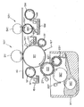
以下、本発明の実施の形態を図面を参照しつつ説明する。図1は本発明の実施の形態に係る画像形成装置を構成する主要構成要素を示す図、図2は画像形成部、現像ユニット及び中間転写体スクイーズ装置の主要構成要素を示す断面図である。画像形成部、現像ユニット及び中間転写体スクイーズ装置は、図1において、イエロー(Y)、マゼンタ(M)、シアン(C)、ブラック(K)からなる各色に対し、同じ構成要素については、各色を表すY、M、C、Kをそれぞれに付して同一番号を用いている。そのうち、イエロー(Y)の画像形成部、現像ユニット及び中間転写体スクイーズ装置の構成を示したのが図2である。以下、各画像形成部、現像ユニット及び中間転写体スクイーズ装置の細部については図2を参照して説明する。   Hereinafter, embodiments of the present invention will be described with reference to the drawings. FIG. 1 is a diagram showing main components constituting an image forming apparatus according to an embodiment of the present invention, and FIG. 2 is a cross-sectional view showing main components of an image forming unit, a developing unit, and an intermediate transfer member squeeze device. In FIG. 1, the image forming unit, the developing unit, and the intermediate transfer member squeeze device are different from each other in the colors of yellow (Y), magenta (M), cyan (C), and black (K). The same numbers are used with Y, M, C, and K representing each. Among them, FIG. 2 shows the configuration of a yellow (Y) image forming unit, a developing unit, and an intermediate transfer member squeeze device. Details of each image forming unit, developing unit, and intermediate transfer member squeeze device will be described below with reference to FIG.

画像形成部は、像担持体10Yの外周の回転方向(移動方向)に沿って、潜像イレーサ16Y、像担持体のクリーニングブレード17Y及び現像剤回収部18Yからなるクリーニング装置、帯電ローラ11Y、露光ユニット12Y、現像ユニット30Yの現像ローラ20Y、像担持体スクイーズローラ13Yとその付属構成であるクリーニングブレード14Y及び現像剤回収部15Yからなるクリーニング装置が配置されている。現像ユニット30Yは、現像ローラ20Yの外周に、クリーニングブレード21Y、アニロックスローラを用いた現像剤供給ローラ32Yとその現像剤供給量を規制する規制ブレード33Y、現像剤圧縮ローラ22Yとその表面の現像剤を書き落とし除去するクリーニングブレード23Yが配置され、液体現像剤が収容された現像剤容器(リザーバ)31Yの中に、現像剤を一様分散状態に攪拌する現像剤攪拌ローラ34Yが配置されている。また、中間転写体40を挟み像担持体10Yと対向する位置に一次転写部50Yの一次転写ローラ51Yが配置され、中間転写体40に沿ってその移動方向下流側に中間転写体スクイーズ装置52Yが、さらに各色の一次転写部50(M、C、K)、中間転写体スクイーズ装置52(M、C、K)が配置されている。中間転写体スクイーズ装置52Yは、中間転写体スクイーズローラ53Y、バックアップローラ54Y、中間転写体スクイーズローラのクリーニングブレード55Y、現像剤回収部15Mにより構成されている。   The image forming unit includes a cleaning device including a latent image eraser 16Y, an image carrier cleaning blade 17Y, and a developer recovery unit 18Y, a charging roller 11Y, and an exposure unit along the rotation direction (movement direction) of the outer periphery of the image carrier 10Y. A cleaning device including a unit 12Y, a developing roller 20Y of the developing unit 30Y, an image carrier squeeze roller 13Y, and a cleaning blade 14Y and a developer recovery unit 15Y, which are auxiliary components, is disposed. The developing unit 30Y includes a cleaning blade 21Y, a developer supply roller 32Y using an anilox roller, a regulating blade 33Y for regulating the developer supply amount, a developer compression roller 22Y, and a developer on the surface of the developing roller 20Y. A cleaning blade 23Y that removes the toner is disposed, and a developer stirring roller 34Y that stirs the developer in a uniformly dispersed state is disposed in a developer container (reservoir) 31Y in which the liquid developer is accommodated. Further, a primary transfer roller 51Y of the primary transfer unit 50Y is disposed at a position facing the image carrier 10Y with the intermediate transfer body 40 interposed therebetween, and an intermediate transfer body squeeze device 52Y is disposed downstream of the intermediate transfer body 40 in the moving direction. Further, a primary transfer portion 50 (M, C, K) for each color and an intermediate transfer body squeeze device 52 (M, C, K) are arranged. The intermediate transfer member squeeze device 52Y includes an intermediate transfer member squeeze roller 53Y, a backup roller 54Y, an intermediate transfer member squeeze roller cleaning blade 55Y, and a developer recovery unit 15M.

現像剤容器31Yに収容される液体現像剤は、従来一般的に使用されている、Isopar(商標:エクソン)をキャリアとした低濃度(1〜2wt%程度)かつ低粘度の、常温で揮発性を有する揮発性液体現像剤ではなく、高濃度かつ高粘度の、常温で不揮発性を有する不揮発性溶剤をキャリアとする液体現像剤である。すなわち、本実施形態における液体現像剤は、熱可塑性樹脂中へ顔料等の着色剤を分散させた平均粒径1μmの固形子を、有機溶媒、シリコンオイル、鉱物油又は食用油等の液体溶媒中へ分散剤とともに添加し、トナー固形分濃度を約25%とした高粘度(30〜10000mPa・s程度)の液体現像剤である。現像剤容器31Yに収容される液体現像剤は、像担持体への現像にともなって変化する現像剤濃度に応じ、現像剤カートリッジ72Yからトナー重量比35〜55%程度の高濃度に分散した現像剤を、キャリアカートリッジ71Yからキャリアをそれぞれ現像剤容器31Yに補給して液体現像剤攪拌ローラ34Yにより攪拌することにより一様分散状態にし、概略重量比でキャリア75%の中にトナー25%を分散させたものである。   The liquid developer accommodated in the developer container 31Y is a low-concentration (about 1 to 2 wt%) and low-viscosity volatile at room temperature using Isopar (trademark: exon) as a carrier, which is generally used conventionally. It is not a volatile liquid developer having a high concentration and a high viscosity, but a liquid developer having a non-volatile solvent at room temperature as a carrier. That is, the liquid developer in the present embodiment is a solid developer having an average particle diameter of 1 μm in which a colorant such as a pigment is dispersed in a thermoplastic resin in a liquid solvent such as an organic solvent, silicon oil, mineral oil, or edible oil. It is a liquid developer having a high viscosity (about 30 to 10,000 mPa · s) which is added together with a dispersant and has a toner solid content concentration of about 25%. The liquid developer accommodated in the developer container 31Y is developed in such a manner that it is dispersed from the developer cartridge 72Y at a high density of about 35 to 55% by weight according to the developer concentration that changes with the development on the image carrier. The carrier is supplied from the carrier cartridge 71Y to the developer container 31Y and stirred by the liquid developer agitating roller 34Y to obtain a uniform dispersion state, and 25% of the toner is dispersed in 75% of the carrier by a general weight ratio. It has been made.

画像形成部及び現像ユニット30Yでは、帯電ローラ11Yにより、像担持体10Yを一様に帯電させ、半導体レーザ、ポリゴンミラー、F−θレンズ等の光学系を有する露光ユニット12Yにより、入力された画像信号に基づいて、変調されたレーザ光を照射して、帯電された像担持体10Y上に静電潜像を形成する。そして、各色(こではイエロー)の液体現像剤を貯蔵する現像剤容器31Yから規制ブレード33Yにより供給現像剤量を規制して現像剤供給ローラ32Yから現像ローラ20Yに現像剤を供給して像担持体10Y上に形成された静電潜像を現像している。   In the image forming unit and developing unit 30Y, the image carrier 10Y is uniformly charged by the charging roller 11Y, and the input image is input by the exposure unit 12Y having an optical system such as a semiconductor laser, a polygon mirror, and an F-θ lens. Based on the signal, a modulated laser beam is irradiated to form an electrostatic latent image on the charged image carrier 10Y. Then, the amount of developer supplied is regulated by the regulating blade 33Y from the developer container 31Y storing the liquid developer of each color (here yellow), and the developer is supplied from the developer supply roller 32Y to the developing roller 20Y to carry the image. The electrostatic latent image formed on the body 10Y is developed.

中間転写体40は、エンドレスの弾性ベルト部材であり、駆動ローラ41とテンションローラ42との間に巻き掛けて張架され、一次転写部50Y、50M、50C、50Kで像担持体10Y、10M、10C、10Kと当接しながら駆動ローラ41により回転駆動される。一次転写部50Y、50M、50C、50Kは、一次転写ローラ51Y、51M、51C、51Kが中間転写体40を挟んで像担持体10Y、10M、10C、10Kと対向配置され、像担持体10Y、10M、10C、10Kとの当接位置を転写位置として、現像された像担持体10Y、10M、10C、10K上の各色のトナー像を中間転写体40上に順次重ねて転写し、フルカラーのトナー像を形成している。中間転写体40には、このように複数の像担持体(感光体)10Y、10M、10C、10Kに形成したトナー像を順次一次転写して重ね合わせて担持し、一括してシート材に二次転写する。そのため、二次転写行程においてシート材にトナー像を転写するに当たって、シート材表面が繊維質などによって平滑でないシート材であっても、この非平滑なシート材表面に倣って二次転写特性を向上させる手段として、弾性ベルト部材を採用している。   The intermediate transfer member 40 is an endless elastic belt member and is wound around and stretched between a driving roller 41 and a tension roller 42. The image transfer members 10Y, 10M, and 50K are primary transfer units 50Y, 50M, 50C, and 50K. It is rotationally driven by the drive roller 41 while abutting 10C and 10K. The primary transfer units 50Y, 50M, 50C, and 50K are arranged such that the primary transfer rollers 51Y, 51M, 51C, and 51K are opposed to the image carriers 10Y, 10M, 10C, and 10K with the intermediate transfer member 40 interposed therebetween. Using the contact position with 10M, 10C, and 10K as the transfer position, the developed toner images of the respective colors on the image carriers 10Y, 10M, 10C, and 10K are sequentially superimposed and transferred onto the intermediate transfer body 40 to obtain a full color toner. An image is formed. The toner images formed on the plurality of image carriers (photosensitive members) 10Y, 10M, 10C, and 10K are sequentially transferred onto the intermediate transfer member 40 in such a manner that the toner images are superimposed and supported on the sheet material. Next transfer. Therefore, when transferring the toner image to the sheet material in the secondary transfer process, even if the sheet material surface is not smooth due to the fiber, etc., the secondary transfer characteristics are improved following this non-smooth sheet material surface. An elastic belt member is employed as the means for making it.

二次転写ユニット60は、二次転写ローラ61が中間転写体40を挟んでベルト駆動ローラ41と対向配置され、さらに二次転写ローラのクリーニングブレード62、現像剤回収部63からなるクリーニング装置が配置される。二次転写ユニット60では、中間転写体40上に色重ねして形成されたフルカラーのトナー画像や単色のトナー画像が二次転写ユニット60の転写位置に到達するタイミングに合せてシート材搬送経路Lにて用紙、フィルム、布等のシート材を搬送、供給し、そのシート材に単色のトナー画像やフルカラーのトナー画像を二次転写する。シート材搬送経路Lの前方には、不図示の定着ユニットが配置され、シート材上に転写された単色のトナー像やフルカラーのトナー像を用紙等の記録媒体(シート材)に融着させ定着させ、最終的なシート材上の画像形成を終了する。二次転写ローラ61も、表面が繊維質などによって平滑でないシート材であっても、この非平滑なシート材表面に倣って二次転写特性を向上させる手段として、表面に弾性体を被覆した弾性ローラで構成している。これは、複数の像担持体10Yに形成したトナー像を順次一次転写して中間転写体40に重ね合わせて担持し、一括してシート材に二次転写する中間転写体40に採用した弾性ベルト部材と同様の目的である。   In the secondary transfer unit 60, a secondary transfer roller 61 is disposed opposite to the belt driving roller 41 with the intermediate transfer body 40 interposed therebetween, and a cleaning device including a cleaning blade 62 and a developer recovery unit 63 of the secondary transfer roller is disposed. Is done. In the secondary transfer unit 60, the sheet material conveyance path L is synchronized with the timing at which a full-color toner image or a single-color toner image formed on the intermediate transfer body 40 reaches the transfer position of the secondary transfer unit 60. Then, a sheet material such as paper, film or cloth is conveyed and supplied, and a single-color toner image or a full-color toner image is secondarily transferred to the sheet material. A fixing unit (not shown) is disposed in front of the sheet material conveyance path L, and a single color toner image or a full color toner image transferred onto the sheet material is fused and fixed to a recording medium (sheet material) such as paper. Image formation on the final sheet material is completed. Even if the secondary transfer roller 61 is a sheet material whose surface is not smooth due to fibers or the like, as a means for improving the secondary transfer characteristics following the surface of the non-smooth sheet material, the surface is coated with an elastic body. It is composed of rollers. This is an elastic belt employed in the intermediate transfer body 40 that sequentially transfers the toner images formed on the plurality of image carriers 10Y, sequentially superimposes them on the intermediate transfer body 40, and transfers them to the sheet material collectively. The purpose is the same as that of the member.

ベルト駆動ローラ41と共に中間転写体40を張架するテンションローラ42側には、その外周に沿って、中間転写体40に当接するように現像剤圧縮ローラ43が対向配置され、その現像剤圧縮ローラ43より中間転写体40の移動方向下流側に、クリーニングブレード46、現像剤回収部47からなるクリーニング装置が配置されている。そして、この現像剤圧縮ローラ43の外周にもクリーニングブレード44、現像剤回収部45からなるクリーニング装置が対向配置され、現像剤圧縮ローラ43に対し、中間転写体40上の残留トナーを中間転写体40に押し付ける方向のバイアスが印加される。二次転写ユニット60を通過後の中間転写体40は、テンションローラ42の巻きかけ部へと進み、現像剤圧縮ローラ43により現像剤が圧縮された後、クリーニングブレード46により中間転写体40上のクリーニングが行われ、再び、一次転写部50へと向かう。   On the side of the tension roller 42 that stretches the intermediate transfer body 40 together with the belt drive roller 41, a developer compression roller 43 is disposed to face the intermediate transfer body 40 along the outer periphery thereof. A cleaning device including a cleaning blade 46 and a developer recovery unit 47 is disposed downstream of the intermediate transfer member 40 in the moving direction of the intermediate transfer member 43. A cleaning device including a cleaning blade 44 and a developer recovery unit 45 is also disposed on the outer periphery of the developer compression roller 43 so that the residual toner on the intermediate transfer body 40 is transferred to the intermediate transfer body with respect to the developer compression roller 43. A bias is applied in the direction of pressing to 40. After passing through the secondary transfer unit 60, the intermediate transfer body 40 proceeds to the winding portion of the tension roller 42, and after the developer is compressed by the developer compression roller 43, the cleaning blade 46 moves the intermediate transfer body 40 onto the intermediate transfer body 40. Cleaning is performed, and the process proceeds to the primary transfer unit 50 again.

現像剤容器31Yにおいて、液体現像剤の中のトナー粒子はプラスの電荷を有し、現像剤は、撹拌ローラ34Yにより撹拌されて一様分散状態になり、現像剤供給ローラ32Yが回転することによって、現像剤容器31Yから汲み上げられ、規制ブレード33Yによって現像剤量が規制されて現像ローラ20Yに供給される。初期的には現像剤容器31Y内に貯蔵した現像剤はキャリア内に概略トナー重量比25%程度で一様分散した状態であるが、像担持体10Yへの現像において画像デューティーが高い現像の場合にはトナー分の消費比率が多く、逆に画像デューティーが低い現像の場合にはトナー分の消費比率が少なくなる。即ち、現像剤容器31Y内に貯蔵された現像剤のトナー重量比率は像担持体10Yへの現像にともなって刻々と変化し、常時この変化を監視して概略トナー重量比25%程度に分散した状態に維持コントロールしていく必要がある。   In the developer container 31Y, the toner particles in the liquid developer have a positive charge. The developer is agitated by the agitation roller 34Y to be in a uniformly dispersed state, and the developer supply roller 32Y rotates. The developer is pumped up from the developer container 31Y, the developer amount is regulated by the regulating blade 33Y, and supplied to the developing roller 20Y. Initially, the developer stored in the developer container 31Y is uniformly dispersed in the carrier at approximately a toner weight ratio of about 25%. However, in the development on the image carrier 10Y, the image duty is high. However, in the case of development with a low image duty, the toner consumption ratio decreases. In other words, the toner weight ratio of the developer stored in the developer container 31Y changes with development on the image carrier 10Y, and this change is constantly monitored and dispersed approximately to a toner weight ratio of about 25%. It is necessary to maintain and control the state.

現像剤容器31Yにおける現像剤を濃度コントロールするため、濃度を検知する手段として、図示省略したトナーの分散重量比率を検知する透過型のフォトセンサあるいは現像剤攪拌ローラ34Yの攪拌トルクを検知するトルク検知手段等及び現像剤容器31Y内の現像剤液面を検知する反射型のフォトセンサ等々が夫々の現像ユニット30Yに設けられる。そして、所定の現像剤量においてトナーの分散重量比率が少なくなった場合にはトナー重量比35〜55%程度の高濃度に分散した現像剤を現像剤カートリッジ72Yから現像剤容器31Yに所定量補充する。逆にトナーの分散重量比率が高くなった場合にはキャリアカートリッジ71Yからキャリアを現像剤容器31Yに所定量補充する。これらの補充により概略トナー重量比25%程度にコントロールしている。また、現像剤の濃度コントロールは、画像信号を管理するコントローラ(CPU)において、出力する画像濃度に応じて現像ユニット30Y内の現像剤濃度を予測して現像剤カートリッジ72Y及びキャリアカートリッジ71Yからの補充量を予測制御することも可能である。このような予測制御によりコントロール応答性と信頼性を高めることができる。   In order to control the density of the developer in the developer container 31Y, as a means for detecting the density, a transmission type photosensor for detecting the dispersion weight ratio of the toner (not shown) or torque detection for detecting the stirring torque of the developer stirring roller 34Y. Each developing unit 30Y is provided with a reflection type photosensor for detecting the means and the developer liquid level in the developer container 31Y. When the toner dispersion weight ratio decreases at a predetermined developer amount, a predetermined amount of developer dispersed at a high concentration of about 35 to 55% is added from the developer cartridge 72Y to the developer container 31Y. To do. Conversely, when the toner dispersion weight ratio increases, a predetermined amount of carrier is replenished from the carrier cartridge 71Y to the developer container 31Y. By these replenishment, the toner weight ratio is controlled to about 25%. The developer density control is performed by a controller (CPU) that manages the image signal, predicting the developer density in the developing unit 30Y according to the output image density, and replenishing from the developer cartridge 72Y and the carrier cartridge 71Y. It is also possible to predictively control the quantity. Such predictive control can improve control responsiveness and reliability.

このように本実施形態の画像形成装置では、現像剤容器31Yに対し、像担持体への現像にともなって変化する現像剤濃度に応じ、現像剤カートリッジ72Yから高濃度に分散した現像剤を、キャリアカートリッジ71Yからキャリアをそれぞれ補給して概略重量比でキャリア75%の中にトナー25%を一様分散させている。この現像剤を用い、種々のプロセス行程を経て画像形成し終段階のシート材に二次転写して図示省略した定着行程に進行する段階において、好ましい二次転写機能及び定着機能を発揮させるためには、当該液体現像剤は概略トナー重量比で40%〜60%程度の分散状態になっていることが望ましい。そのため、適宜複数の位置に余剰現像剤、余剰キャリアを除去し回収する、所謂現像剤回収手段として、上記のようなクリーニングブレードを有する像担持体スクイーズ装置(13〜15)、像担持体クリーニング装置(17、18)、中間転写体スクイーズ装置(52〜55)、中間転写体クリーニング装置(42〜47)、さらには二次転写ローラクリーニング装置(62、63)等を配置している。これらのクリーニングブレードが、例えば像担持体スクイーズローラ13Yのクリーニングブレード14Y、像担持体10Yのクリーニングブレード17Y、中間転写体スクイーズ装置52Yのクリーニングブレード55Y、二次転写ローラ61のクリーニングブレード62、中間転写体現像剤圧縮ローラ43のクリーニングブレード44、中間転写体40のクリーニングブレード46である。   As described above, in the image forming apparatus according to the present embodiment, the developer dispersed from the developer cartridge 72Y to the developer container 31Y in a high concentration according to the developer concentration that changes as the image carrier is developed. Each carrier is replenished from the carrier cartridge 71Y, and 25% of the toner is uniformly dispersed in 75% of the carrier in an approximate weight ratio. In order to exhibit a preferable secondary transfer function and fixing function in a stage where an image is formed through various process steps, is secondarily transferred to a final stage sheet material, and proceeds to a fixing step (not shown) using this developer. It is desirable that the liquid developer is in a dispersion state of approximately 40% to 60% in approximate toner weight ratio. Therefore, the image carrier squeeze device (13-15) and the image carrier cleaning device having the cleaning blade as described above as so-called developer collecting means for removing and collecting excess developer and excess carrier at a plurality of positions as appropriate. (17, 18), an intermediate transfer member squeeze device (52-55), an intermediate transfer member cleaning device (42-47), and a secondary transfer roller cleaning device (62, 63). These cleaning blades are, for example, the cleaning blade 14Y of the image carrier squeeze roller 13Y, the cleaning blade 17Y of the image carrier 10Y, the cleaning blade 55Y of the intermediate transfer body squeeze device 52Y, the cleaning blade 62 of the secondary transfer roller 61, and the intermediate transfer. These are a cleaning blade 44 for the body developer compression roller 43 and a cleaning blade 46 for the intermediate transfer body 40.

本実施形態において、例えば1色目の現像剤回収部15Yにクリーニングブレード14Yで掻き落とし回収した現像剤と現像剤回収部45にクリーニングブレード44で掻き落とし回収した現像剤と現像剤回収部47にクリーニングブレード46で掻き落とし回収した現像剤を同一の流路を合流させる。そして、現像剤回収部18Yにクリーニングブレード17Yで掻き落とし回収した現像剤と現像剤回収部15Mにクリーニングブレード55Y及び次の色のクリーニングブレード14Mで掻き落とし回収した現像剤を同一の流路を合流させ、2色目以降も同様に回収した現像剤を同一の流路に合流させる。そして、4色目の現像剤回収部18Kにクリーニングブレード17Kで掻き落とし回収した現像剤と現像剤回収部56Kにクリーニングブレード55Kで掻き落とし回収した現像剤を同一の流路に合流させる。さらに、これら合流させた流路と現像剤回収部63にクリーニングブレード62で掻き落とし回収した現像剤の流路を現像剤回収流路70に併合してポンプ76からフィルタ手段77に搬送する。   In this embodiment, for example, the developer scraped and collected by the cleaning blade 14Y in the developer collecting section 15Y for the first color and the developer scraped and collected by the cleaning blade 44 in the developer collecting section 45 and cleaned by the developer collecting section 47 are cleaned. The developer scraped and collected by the blade 46 is joined in the same flow path. Then, the developer scraped and collected by the cleaning blade 17Y in the developer collecting portion 18Y and the developer scraped and collected by the cleaning blade 55Y and the cleaning blade 14M of the next color are joined to the developer collecting portion 15M through the same flow path. In the second and subsequent colors, the collected developer is similarly merged into the same flow path. Then, the developer scraped and collected by the cleaning blade 17K in the developer collecting unit 18K for the fourth color and the developer scraped and collected by the cleaning blade 55K in the developer collecting unit 56K are merged into the same flow path. Further, the combined flow path and the developer flow path scraped and collected by the cleaning blade 62 into the developer recovery section 63 are merged with the developer recovery flow path 70 and conveyed from the pump 76 to the filter means 77.

このように各クリーニングブレードにより掻き落とし回収された現像剤は、搬送する流路を併合した回収流路70からフィルタ77を通してキャリアバッファタンク74に貯蔵し再利用を可能にしている。複数の現像ユニットから現像された現像剤を回収すると、トナーが混色状態になり、回収したままで再利用することはできないので、搬送経路にフィルタ手段77を設けてトナー粒子をフィルタリングしてキャリアのみを再利用可能にしているのである。キャリアバッファタンク74に貯蔵されたキャリアの再利用は、現像剤搬送路78を通してキャリアカートリッジ71Yに分配搬送することによって、現像剤容器(リザーバ)31Yに現像剤カートリッジ72Yからの現像剤の補給と共にキャリアカートリッジ71Yからキャリアを補給することによって行われる。   The developer thus scraped and collected by each cleaning blade is stored in the carrier buffer tank 74 through the filter 77 from the collection channel 70 combined with the channel to be transported, and can be reused. When the developer developed from a plurality of developing units is collected, the toner is mixed and cannot be reused as it is collected. Therefore, filter means 77 is provided in the transport path to filter the toner particles and only the carrier. Is reusable. The reuse of the carrier stored in the carrier buffer tank 74 is performed by supplying the developer from the developer cartridge 72Y to the developer container (reservoir) 31Y by distributing and transporting the carrier to the carrier cartridge 71Y through the developer transport path 78. This is performed by supplying a carrier from the cartridge 71Y.

フィルタ手段77は、各現像剤回収手段を通して回収された現像剤の流路を回収流路に併合してからフィルタリングしトナー固形成分や紙粉をキャリア成分から分離するものであり、例えば濾紙や静電フィルタその他のフィルタが用いられる。トナー等が分離され再利用可能になったキャリアはキャリアバッファタンク74に貯蔵し、一旦バッファに貯蔵したキャリアを複数の現像ユニットのキャリアカートリッジ71Yへそれぞれ分配搬送して再利用するシステムにすることによってキャリア再利用率が平均化し安定した再利用を可能にしている。そのため、現像剤を搬送するためのポンプ76はフィルタ手段77と共に共通に機能させ搬送経路と共にシンプルかつ安価な構成を実現することができる。また、二次転写ローラ61及び中間転写体40のクリーニング装置から回収する現像剤には異物や紙紛等を含んでいる場合があるので、再利用せずに廃却する方法もある。しかし、本実施形態のようにフィルタリング行程を設定して、異物や紙紛等も合せてフィルタリングすることにより、各部からの回収現像剤を再利用可能にしている。なお、フィルタ手段77に除去された混色トナー及び異物や紙紛等は、図示省略したフィルタ状態の検知手段の検知結果に基づいて交換するシステムにすることで、フィルタリング機能を安定して維持することができる。   The filter unit 77 merges the developer channels collected through the developer collecting units with the collection channel and then filters the toner solid component and paper powder from the carrier component. An electric filter or other filter is used. The carrier that has been separated from the toner and becomes reusable is stored in the carrier buffer tank 74, and the carrier once stored in the buffer is distributed and transported to the carrier cartridges 71Y of the plurality of developing units to be reused. Carrier reuse rate is averaged to enable stable reuse. Therefore, the pump 76 for transporting the developer functions in common with the filter unit 77, and a simple and inexpensive configuration can be realized together with the transport path. Further, since the developer recovered from the cleaning device for the secondary transfer roller 61 and the intermediate transfer member 40 may contain foreign matter, paper dust, and the like, there is a method of discarding without reuse. However, the collected developer from each part can be reused by setting a filtering process as in the present embodiment and filtering foreign matter and paper dust together. Note that the color mixing toner, foreign matter, paper dust, and the like removed by the filter unit 77 are exchanged based on the detection result of the filter state detection unit (not shown) to stably maintain the filtering function. Can do.

キャリア成分は、現像剤カートリッジ72Yから補給するトナー重量比が高いときには相対的に不足になる場合が生じ、逆に現像剤カートリッジから補給するトナー重量比が低いときには相対的に余剰になる場合が生ずる。キャリア成分が不足になる場合、本実施形態では、現像剤カートリッジ72Yと共にキャリア搬送路経路内にキャリアカートリッジ71Yを着脱可能に構成することにより補給操作を簡便に行えるようにしている。また、トナー重量比が低いときだけでなく、画像デューティーが高い現像のときにも現像剤の消費と共に、現像剤カートリッジ72Yからトナー重量比35〜55%程度の現像剤を補給しながら二次転写、定着時には40%〜60%程度までトナー重量比を上げるので、キャリアの回収量が多くなり、キャリア成分は、相対的に余剰になってくる。このように現像剤カートリッジ72Yには、トナー重量比35〜55%程度の高濃度に分散した現像剤が収容されているので、画像デューティーが高い現像により現像剤が消費されれば、それだけキャリア成分の回収が相対的に余剰になる。キャリア成分が余剰になる場合、本実施形態では、キャリアバッファタンク74とは別にもうひとつのキャリア収納タンク73を着脱可能に設けることにより満杯になったキャリア収納タンク73をキャリアとともに除去可能な構成にしている。このようにすると、満杯のキャリア収納タンクを空のキャリア収納タンクと交換して保管することが可能になるので、無駄のない効率的なキャリアの再利用が可能になるとともにキャリアバッファタンク74の容量を極端に大きく設定する必要がなく装置の小型化に有用である。   The carrier component may be relatively short when the toner weight ratio supplied from the developer cartridge 72Y is high, and conversely, the carrier component may be relatively excessive when the toner weight ratio supplied from the developer cartridge is low. . In the present embodiment, when the carrier component becomes insufficient, the replenishment operation can be easily performed by configuring the carrier cartridge 71Y in the carrier transport path along with the developer cartridge 72Y so as to be detachable. Further, not only when the toner weight ratio is low, but also when developing with a high image duty, the secondary transfer is performed while supplying the developer from the developer cartridge 72Y with a toner weight ratio of about 35 to 55% as the developer is consumed. During fixing, the toner weight ratio is increased to about 40% to 60%, so that the amount of recovered carrier increases, and the carrier component becomes relatively surplus. As described above, since the developer cartridge 72Y contains the developer dispersed at a high density of about 35 to 55% by weight of the toner, the more the developer is consumed by the development with a high image duty, the more the carrier component. Recovering is relatively surplus. In the present embodiment, when the carrier component becomes excessive, in this embodiment, another carrier storage tank 73 is detachably provided separately from the carrier buffer tank 74 so that the full carrier storage tank 73 can be removed together with the carrier. ing. This makes it possible to replace the full carrier storage tank with an empty carrier storage tank and store it, thereby enabling efficient and efficient reuse of the carrier and the capacity of the carrier buffer tank 74. This is useful for downsizing the apparatus.

また、キャリアカートリッジ71Yを省き、キャリアバッファタンク74から直接現像剤容器31Yにキャリアを適宜補給するように構成することもできる。現像剤カートリッジ72Yと共にキャリア搬送路経路内にキャリアカートリッジ71Yを着脱可能に構成し、さらに、キャリアカートリッジ71Yをキャリア収納タンク73と着脱互換性を有する構成にしておくと、空になったキャリアカートリッジ71Yをキャリア収納タンク73としてそのまま活用することが可能であり、利便性を高めることができる。なお、キャリアカートリッジ71Y、キャリア収納タンク73に対してキャリアはキャリア搬送路と双方向に流出入可能であっても良いが、チェック弁機能を有して流出を阻止するように接続すると、着脱操作にも好都合である。   Alternatively, the carrier cartridge 71Y may be omitted, and the carrier may be appropriately supplied directly from the carrier buffer tank 74 to the developer container 31Y. When the carrier cartridge 71Y is configured to be detachable in the carrier transport path along with the developer cartridge 72Y, and the carrier cartridge 71Y is configured to be detachable and compatible with the carrier storage tank 73, the carrier cartridge 71Y that has become empty can be obtained. Can be used as the carrier storage tank 73 as it is, and convenience can be improved. The carrier may be able to flow in and out of the carrier cartridge 71Y and the carrier storage tank 73 in both directions. However, if the carrier has a check valve function so as to prevent the outflow, the detachment operation is possible. Also convenient.

一方、現像剤の配合手段として現像ユニットとは別に設けた配合ボトルなどで配合してから現像剤容器31Yに供給してもよいが、刻々と変化する現像剤容器31Y内の現像剤濃度に対してコントロールのタイムラグが生じないようにする為には、相応の配慮が必要になる。本実施形態のように、現像ユニット内にトナーの分散重量比率を検知する検知手段及び現像剤量を検知する検知手段の検知内容に基づいて高濃度に分散した現像剤及びキャリアを現像剤容器31Y内に補給し攪拌して一様分散させる構成とすることにより、濃度コントロールのタイムラグもなく安定した濃度コントロールが達成される。   On the other hand, it may be supplied to the developer container 31Y after being blended in a blending bottle or the like provided separately from the developing unit as a developer blending means, but with respect to the developer concentration in the developer container 31Y that changes every moment. Therefore, in order to prevent the time lag of control, appropriate consideration is necessary. As in the present embodiment, the developer and the carrier dispersed in a high concentration based on the detection contents of the detection means for detecting the dispersion weight ratio of the toner and the detection means for detecting the developer amount in the developing unit are stored in the developer container 31Y. By adopting a configuration in which the water is replenished and stirred to uniformly disperse, stable concentration control can be achieved without a time lag of concentration control.

上記のように本実施形態は、現像剤回収手段の有するクリーニング装置により現像剤を掻き落として回収し現像ユニット30Yに分配搬送し再利用しているが、さらに、それぞれ現像剤回収手段について説明する。現像ユニット30Yでは、現像ローラ20Yに担持された液体現像剤のトナーを圧縮状態にする現像剤圧縮ローラ22Yのクリーニングを行うクリーニングブレード23Y、現像ローラ20Yのクリーニングを行うクリーニングブレード21Yを有する。クリーニングブレード21Yは、現像ローラ20Yが像担持体10Yと当接する現像ニップ部より現像ローラ20Yの回転方向の下流側に配置されて、現像ローラ20Yに残存する現像剤を掻き落とし、クリーニングブレード23Yは、図中矢印方向に回転して現像剤圧縮ローラ22Yの現像剤を掻き落として除去しリザーバ31Y内の現像剤に合流(併合)させて再利用される。尚、これら合流するキャリア及びトナーは混色状態にはない。   As described above, in the present embodiment, the developer is scraped off and collected by the cleaning device included in the developer collecting means, and is distributed and conveyed to the developing unit 30Y for reuse. Further, each developer collecting means will be described. . The development unit 30Y includes a cleaning blade 23Y that cleans the developer compression roller 22Y that compresses the liquid developer toner carried on the development roller 20Y, and a cleaning blade 21Y that cleans the development roller 20Y. The cleaning blade 21Y is disposed on the downstream side in the rotation direction of the developing roller 20Y from the developing nip portion where the developing roller 20Y contacts the image carrier 10Y, and scrapes off the developer remaining on the developing roller 20Y. The developer in the developer compression roller 22Y is scraped off and removed by rotating in the direction of the arrow in the figure, and the developer in the reservoir 31Y is joined (joined) to be reused. Note that the merged carrier and toner are not in a mixed color state.

像担持体スクイーズ装置は、像担持体10Yに対向して現像ローラ20Yより回転方向下流側に配置され、像担持体スクイーズローラ13Yと、該像担持体スクイーズローラ13Yに押圧摺接して表面をクリーニングするクリーニングブレード14Yと現像剤回収部15Yから構成され、像担持体10Yに現像された現像剤から余剰なキャリア及び本来不要なカブリトナーを回収し、顕像内のトナー粒子比率を上げる機能を有する。本実施形態では、像担持体スクイーズローラ13Yを像担持体10Yに対して略同一周速度でウィズ回転させ、像担持体10Yに現像された現像剤から重量比5〜10%程度の余剰キャリアを回収して双方の回転駆動負荷を軽減するとともに、像担持体10Yの顕像トナー像への外乱作用を抑制している。像担持体スクイーズローラ13Yによって回収された余剰なキャリア及び不要なカブリトナーはクリーニングブレード14Yの作用によって像担持体スクイーズローラ13Yから現像剤回収部15Yに回収してプールされる。尚、この回収した余剰なキャリア及びカブリトナーは専用の孤立した像担持体10Yから回収しているので各色の画像形成部において混色現象は発生しない。   The image carrier squeeze device is disposed on the downstream side in the rotational direction from the developing roller 20Y so as to face the image carrier 10Y, and presses and slides against the image carrier squeeze roller 13Y to clean the surface. The cleaning blade 14Y and the developer recovery unit 15Y have a function of recovering excess carrier and originally unnecessary fog toner from the developer developed on the image carrier 10Y and increasing the toner particle ratio in the visible image. . In this embodiment, the image carrier squeeze roller 13Y rotates with the image carrier 10Y at substantially the same peripheral speed, and an excess carrier of about 5 to 10% by weight from the developer developed on the image carrier 10Y. Both the rotational driving loads are collected to reduce the disturbance effect on the visible toner image of the image carrier 10Y. Excess carrier and unnecessary fog toner collected by the image carrier squeeze roller 13Y are collected from the image carrier squeeze roller 13Y by the action of the cleaning blade 14Y and pooled. Note that the collected surplus carrier and fog toner are collected from the dedicated isolated image carrier 10Y, so that no color mixing phenomenon occurs in the image forming portions of the respective colors.

一次転写部50Yでは、像担持体10Yと中間転写体40が等速度で移動して像担持体10Yに現像された現像剤像を一次転写ローラ51Yにより中間転写体40へ転写することにより、回転及び移動の駆動負荷を軽減するとともに、像担持体10Yの顕像トナー像への外乱作用を抑制している。なお、1色目の一次転写部50Yでは初回一次転写なので混色現象は発生しないが、2色目以降は既に一次転写されたトナー像部位に更に異なるトナー像を転写して色重ねするので中間転写体40から像担持体10(M、C、K)へトナーが移行する所謂逆転写現像によって逆転写トナーと転写残りトナーは混色して余剰キャリアとともに像担持体10(M、C、K)に担持されて移動し、クリーニングブレード17(M、C、K)の作用によって像担持体から回収してプールされる。   In the primary transfer unit 50Y, the image carrier 10Y and the intermediate transfer member 40 move at the same speed, and the developer image developed on the image carrier 10Y is transferred to the intermediate transfer member 40 by the primary transfer roller 51Y. In addition, the driving load of movement is reduced, and the disturbance effect on the visible toner image of the image carrier 10Y is suppressed. The primary transfer portion 50Y for the first color does not cause a color mixing phenomenon since it is the first primary transfer, but since the second and subsequent colors transfer different toner images onto the already transferred primary toner image portions and superimpose colors, the intermediate transfer body 40 is used. The reverse transfer development causes the toner to transfer from the toner to the image carrier 10 (M, C, K), and the reverse transfer toner and the untransferred toner are mixed and carried on the image carrier 10 (M, C, K) together with the surplus carrier. Moved from the image carrier by the action of the cleaning blade 17 (M, C, K) and pooled.

終段階のシート材に二次転写して図示省略した定着行程に進行する段階で、好ましい二次転写機能及び定着機能を発揮させるために、現像剤(キャリア内に分散したトナー)の望ましい分散状態は、前述したように概略トナー重量比で40%〜60%程度である。中間転写体スクイーズ装置52Yは、この終段階に現像剤が望ましい分散状態に至っていない場合に、中間転写体40から更に余剰キャリアを除去する手段として設けられている。中間転写体スクイーズ装置52Yは、一次転写部50Yより中間転写体40の移動方向下流側に配置され、中間転写体スクイーズローラ53Y、中間転写体40を挟んで中間転写体スクイーズローラ53Yと対向配置されるバックアップローラ54Y、中間転写体スクイーズローラ53Yに押圧摺接して表面をクリーニングするクリーニングブレード55Y及び現像剤回収部15Mから構成され、中間転写体40に一次転写された現像剤から余剰なキャリアを回収し、顕像内のトナー粒子比率を上げると共に、本来不要なカブリトナーを回収する機能を有する。現像剤回収部15Mは、中間転写体40の移動方向下流側に配置されたマゼンタの像担持体スクイーズローラのクリーニングブレード14Mで回収されるキャリアの回収機構を中間転写体スクイーズローラ53Yのクリーニングブレード55Yにも兼用するものである。このように2色目以降の像担持体スクイーズ装置の現像剤回収部15(M、C、K)において、その前の色の一次転写部50(Y、M、C)より中間転写体40の移動方向下流側に配置された中間転写体スクイーズ装置52(Y、M、C)の現像剤回収部として兼用することにより、それらの間隔を一定に規制することができ、構造を簡潔にして小型化を図ることができる。   Desirable dispersion state of the developer (toner dispersed in the carrier) in order to perform a preferable secondary transfer function and fixing function at the stage of secondary transfer to the final stage sheet material and proceeding to the fixing process not shown in the figure. Is approximately 40% to 60% in terms of the toner weight ratio as described above. The intermediate transfer member squeeze device 52Y is provided as means for further removing excess carrier from the intermediate transfer member 40 when the developer has not reached the desired dispersion state at this final stage. The intermediate transfer member squeeze device 52Y is disposed downstream of the primary transfer unit 50Y in the moving direction of the intermediate transfer member 40, and is disposed opposite to the intermediate transfer member squeeze roller 53Y and the intermediate transfer member squeeze roller 53Y across the intermediate transfer member 40. The backup roller 54Y, the intermediate transfer member squeeze roller 53Y, and a cleaning blade 55Y that cleans the surface by sliding contact with the intermediate transfer member squeeze roller 53Y and a developer recovery unit 15M, and recovers excess carrier from the developer primarily transferred to the intermediate transfer member 40. In addition, the function of increasing the toner particle ratio in the visible image and collecting originally unnecessary fog toner is provided. The developer recovery unit 15M uses a recovery mechanism for a carrier recovered by the cleaning blade 14M of the magenta image carrier squeeze roller disposed downstream in the moving direction of the intermediate transfer member 40, as a cleaning blade 55Y of the intermediate transfer member squeeze roller 53Y. It is also used for both. In this way, in the developer recovery unit 15 (M, C, K) of the image carrier squeeze device for the second and subsequent colors, the intermediate transfer member 40 is moved from the primary transfer unit 50 (Y, M, C) of the preceding color. By using it as the developer recovery part of the intermediate transfer member squeeze device 52 (Y, M, C) arranged on the downstream side in the direction, the interval between them can be regulated uniformly, and the structure is simplified and reduced in size. Can be achieved.

なお、1色目の中間転写体スクイーズ部位では初回中間転写体スクイーズなので混色現象は発生しないが、2色目以降は既に一次転写されたトナー像部位に更に異なるトナー像が転写されて色重ねされているので中間転写体40から中間転写体スクイーズローラ53Yへトナーが移行した場合のトナーは混色して余剰キャリアとともに中間転写体スクイーズローラ53Yに担持されて移動し、クリーニングブレードの作用によって中間転写体スクイーズローラ53Yから回収してプールされる。また、上述した中間転写体スクイーズ行程上流側の一次転写部位の像担持体10Yによるスクイーズ能力及び像担持体スクイーズローラ53Yのスクイーズ能力が充分な能力をもって行われる場合には、必ずしも全ての一次転写行程より中間転写体40の移動方向下流側に中間転写体スクイーズ装置52を設ける必要はない。   The first color intermediate squeeze squeeze part is the first intermediate squeeze squeeze, so no color mixing phenomenon occurs. However, after the second color, a different toner image is transferred to the already transferred primary toner image part and overlaid. Therefore, when the toner is transferred from the intermediate transfer body 40 to the intermediate transfer body squeeze roller 53Y, the toner is mixed in color and carried and moved by the intermediate transfer body squeeze roller 53Y together with the surplus carrier. Collected from 53Y and pooled. Further, when the squeeze ability by the image carrier 10Y at the primary transfer site upstream of the intermediate transfer member squeeze process and the squeeze ability of the image carrier squeeze roller 53Y are performed with sufficient ability, not all primary transfer processes are performed. It is not necessary to provide the intermediate transfer body squeeze device 52 further downstream in the moving direction of the intermediate transfer body 40.

中間転写体40上に色重ねしたトナー像が二次転写部位に到達するタイミングに合わせてシート材を供給し、シート材にトナー画像を二次転写して定着行程へと進め最終的なシート材上の画像形成を終了するが、ジャムなどのシート材供給トラブルが発生した場合には、全てのトナー画像が二次転写ロールに転写されて回収されるものではなく、一部は中間転写体上に残り、また、通常の二次転写行程においても中間転写体40上のトナー像は100%二次転写されてシート材に移行するものではなく、数パーセントの二次転写残りが発生する。特に、ジャムなどのシート材供給トラブルが発生した場合には、シート材が介在しない状態でトナー画像が二次転写ローラ61に接して転写されシート材裏面汚れを引き起こす。これら不要トナー像に対し、現像剤圧縮ローラ43に、液体現像剤のトナー粒子を中間転写体40側に押しつける方向のバイアス、つまり、トナー粒子の帯電極性と同極性のバイアスを印加する。ジャムなどのトラブルが発生した場合に印加するこのバイアスは、二次転写ローラ61や中間転写体スクイーズローラ53Y(いずれか)に印加してもよい。このことにより、中間転写体40に残った液体現像剤のトナー粒子を中間転写体40側に押しつけて現像剤圧縮状態にして、二次転写ローラ61側にキャリア液を回収(スクイーズ)し、効率よく中間転写体のクリーニングブレード46による中間転写体40上のクリーニング、二次転写ローラのクリーニングブレード62による二次転写ローラ61のクリーニングを行う。このように二次転写ローラのクリーニングブレード62は、二次転写ローラ61に転写された現像剤(キャリア内に分散したトナー)を除去する手段として備え、二次転写ローラ61から現像剤を回収してプールされる。このプールした現像剤は混色状態のものであり、紙粉等の異物も含んでいる場合があるが、これらは前述したようにフィルタ77によって分離される。   The sheet material is supplied in accordance with the timing at which the toner image superimposed on the intermediate transfer body 40 reaches the secondary transfer portion, and the toner image is secondarily transferred to the sheet material and proceeds to the fixing process, and the final sheet material When the above image formation is completed, but a sheet material supply trouble such as a jam occurs, not all the toner images are transferred to the secondary transfer roll and collected. In addition, in the normal secondary transfer process, the toner image on the intermediate transfer body 40 is not 100% secondary-transferred and transferred to the sheet material, and a secondary transfer residue of several percent occurs. In particular, when a sheet material supply trouble such as a jam occurs, the toner image is transferred in contact with the secondary transfer roller 61 without the sheet material interposed, and the back surface of the sheet material is stained. A bias in a direction in which the toner particles of the liquid developer are pressed against the intermediate transfer body 40, that is, a bias having the same polarity as the charging polarity of the toner particles is applied to the developer compression roller 43 with respect to these unnecessary toner images. This bias applied when a trouble such as a jam occurs may be applied to the secondary transfer roller 61 or the intermediate transfer member squeeze roller 53Y (any one). As a result, the toner particles of the liquid developer remaining on the intermediate transfer member 40 are pressed against the intermediate transfer member 40 to be in a developer compressed state, and the carrier liquid is collected (squeezed) on the secondary transfer roller 61 side to improve efficiency. The intermediate transfer member 40 is often cleaned by the intermediate transfer member cleaning blade 46 and the secondary transfer roller 61 is cleaned by the secondary transfer roller cleaning blade 62. Thus, the cleaning blade 62 of the secondary transfer roller is provided as a means for removing the developer (toner dispersed in the carrier) transferred to the secondary transfer roller 61, and collects the developer from the secondary transfer roller 61. Pooled. The pooled developer is in a mixed color state and may contain foreign matters such as paper dust, but these are separated by the filter 77 as described above.

図3は本発明に係る画像形成装置の他の実施形態を説明する図であり、1色目の像担持体10Yの一次転写部50Yより回転方向の上流側に配置される像担持体スクィーズ装置(13Y、14Y、15Y)と、中間転写体クリーニング装置(46、47)より回収された現像剤を同一の流路に合流させ、他の回収流路70とは別の回収流路70′、ポンプ76′、フィルタ77′を通してキャリアバッファタンク74に搬送するように構成している。中間転写体クリーニング装置では、現像剤と共にシート材の紙粉等の不要物も回収され流動性に劣る。そこで、このように1色目の像担持体スクィーズ装置から回収された現像剤と流路を同一にして回収することで、回収する搬送路においてキャリアリッチにして流動性を向上させ、回収をし易くしている。なお、中間転写体クリーニング装置は、中間転写体40の二次転写ユニット60より移動方向の下流側で1色目の一次転写部50Yより移動方向の下流側の位置に配置されていることになる。さらに、図2に示す帯電ローラ11Y、現像剤圧縮ローラ22Yとして、ローラに代えてコロナ放電器を用い、コロナ放電器によりコロナ放電させて像担持体10Yを一様に帯電させ、現像剤のトナー粒子を現像ローラ20Y側に押しつけ現像剤圧縮状態にするように構成している。また、中間転写体クリーニング装置では、図1に示した現像剤圧縮ローラ43、クリーニングブレード44、現像剤回収部45を省くこともでき、その構成を示している。   FIG. 3 is a diagram for explaining another embodiment of the image forming apparatus according to the present invention. An image carrier squeeze device (on the upstream side in the rotation direction from the primary transfer portion 50Y of the first color image carrier 10Y) 13Y, 14Y, 15Y) and the developer recovered from the intermediate transfer body cleaning device (46, 47) are merged into the same flow path, and the recovery flow path 70 ', which is different from the other recovery flow paths 70, and the pump 76 'and the filter 77' are configured to be conveyed to the carrier buffer tank 74. In the intermediate transfer member cleaning device, unnecessary substances such as paper dust of the sheet material are collected together with the developer, and the fluidity is poor. Therefore, by collecting the developer collected from the image carrier squeeze device for the first color in the same flow path, the developer is made rich in the collecting conveyance path to improve the fluidity and facilitate the collection. is doing. The intermediate transfer body cleaning device is disposed at a position downstream of the secondary transfer unit 60 of the intermediate transfer body 40 in the movement direction and downstream of the first color primary transfer portion 50Y in the movement direction. Further, as the charging roller 11Y and the developer compression roller 22Y shown in FIG. 2, a corona discharger is used instead of the roller, and the image carrier 10Y is uniformly charged by corona discharge by the corona discharger, thereby developing toner. The particles are pressed against the developing roller 20Y to be in a developer compressed state. Further, in the intermediate transfer body cleaning device, the developer compression roller 43, the cleaning blade 44, and the developer recovery unit 45 shown in FIG. 1 can be omitted, and the configuration thereof is shown.

なお、本発明は、上記実施の形態に限定されるものではなく、種々の変形が可能である。例えば上記実施の形態では、中間転写体としてエンドレスの弾性ベルト部材を用い、その中間転写体上に各現像色に対応する複数の画像形成部を並列配置したタンデム型のカラー画像形成装置により説明したが、円筒状の回転支持体に各現像色に対応する複数の画像形成部を支持し、回転支持体の回転によりそれぞれの画像形成部を中間転写体の転写位置に順次移動させて各色のトナー画像を順次重ねて転写するロータリー型のカラー画像形成装置に適用し、さらに中間転写ドラムを用いてもよい。この場合、中間転写体上に設けられる中間転写体クリーニングブレードは、画像形成部から中間転写体へトナー画像を転写する一次転写プロセス中、さらに中間転写体から記録媒体に転写するフルカラーのトナー画像や単色のトナー画像が通過するまでの間、中間転写体から離間させ、その後、所謂印字動作終了後、中間転写体にエッジ当接させ押圧摺接させる。   In addition, this invention is not limited to the said embodiment, A various deformation | transformation is possible. For example, in the above-described embodiment, an endless elastic belt member is used as an intermediate transfer member, and a tandem color image forming apparatus in which a plurality of image forming units corresponding to each development color are arranged in parallel on the intermediate transfer member has been described. Supports a plurality of image forming portions corresponding to each development color on a cylindrical rotating support, and sequentially rotates each image forming portion to the transfer position of the intermediate transfer member by rotating the rotating support. The present invention may be applied to a rotary type color image forming apparatus that transfers images in a superimposed manner, and an intermediate transfer drum may be used. In this case, the intermediate transfer member cleaning blade provided on the intermediate transfer member is a full-color toner image that is further transferred from the intermediate transfer member to the recording medium during the primary transfer process of transferring the toner image from the image forming unit to the intermediate transfer member. The single-color toner image is separated from the intermediate transfer member until it passes, and then after the so-called printing operation is finished, the intermediate transfer member is brought into edge contact and pressure-sliding contact.

本発明の実施の形態に係る画像形成装置を構成する主要構成要素を示す図である。1 is a diagram illustrating main components constituting an image forming apparatus according to an embodiment of the present invention. 画像形成部、現像ユニット及び中間転写体スクイーズ装置の主要構成要素を示す断面図である。FIG. 3 is a cross-sectional view illustrating main components of an image forming unit, a developing unit, and an intermediate transfer body squeeze device. 本発明に係る画像形成装置の他の実施の形態を説明する図である。It is a figure explaining other embodiment of the image forming apparatus which concerns on this invention.

符号の説明Explanation of symbols

10…像担持体、11…帯電ローラ、12…露光ユニット、13…像担持体スクイーズローラ、14、17、21、23、44、46、55、62…クリーニングブレード、15、18、45、47、63…現像剤回収部、16…潜像イレーサ、20…現像ローラ、22…現像剤圧縮ローラ、30…現像ユニット、31…現像剤容器、32…現像剤供給ローラ、33…規制ブレード、21、34…撹拌ローラ、40…中間転写体、41、42…ベルト駆動ローラ、43…現像剤圧縮ローラ、50…一次転写部、51…一次転写バックアップローラ、52…中間転写体スクイーズ装置、53…中間転写体スクイーズローラ、54…バックアップローラ、60…二次転写ユニット、61…二次転写ローラ、70…現像剤回収流路、71…キャリアカートリッジ、72…現像剤カートリッジ、73…キャリア収納タンク、74…キャリアバッファタンク、75、76…ポンプ、77…フィルタ、78…現像剤搬送路 DESCRIPTION OF SYMBOLS 10 ... Image carrier, 11 ... Charge roller, 12 ... Exposure unit, 13 ... Image carrier squeeze roller, 14, 17, 21, 23, 44, 46, 55, 62 ... Cleaning blade, 15, 18, 45, 47 , 63 ... developer recovery unit, 16 ... latent image eraser, 20 ... developing roller, 22 ... developer compression roller, 30 ... developing unit, 31 ... developer container, 32 ... developer supply roller, 33 ... regulating blade, 21 34 ... Stirring roller, 40 ... Intermediate transfer member, 41, 42 ... Belt drive roller, 43 ... Developer compression roller, 50 ... Primary transfer part, 51 ... Primary transfer backup roller, 52 ... Intermediate transfer member squeeze device, 53 ... Intermediate transfer body squeeze roller, 54 ... backup roller, 60 ... secondary transfer unit, 61 ... secondary transfer roller, 70 ... developer recovery flow path, 71 ... carrier Cartridges, 72 ... developer cartridge, 73 ... carrier storage tank, 74 ... carrier buffer tank, 75 and 76 ... pumps, 77 ... Filter, 78 ... developer conveying path

Claims (5)

複数の像担持体と、前記複数の像担持体上の形成された静電潜像を不揮発性溶剤をキャリアとするそれぞれ異なる色の液体現像剤を用いて現像する複数の現像装置と、前記複数の像担持体のそれぞれに対応する一次転写部で前記現像された現像剤像を順次転写して重ね合わせ担持し搬送する中間転写体と、前記中間転写体から重ね合わせた現像剤像を二次転写部で搬送路上のシート材に転写して出力する出力装置とを備え、現像剤回収手段を複数の位置に配置して余剰現像剤を回収し画像形成を行うようにした画像形成装置において、前記現像剤回収手段として、前記像担持体それぞれの前記一次転写部より回転方向上流側に配置される像担持体スクィーズ装置と、前記中間転写体の前記一次転写部のそれぞれより移動方向下流側に配置される中間転写体スクィーズ装置を備え、前記中間転写体の移動方向の最下流側に配置された前記中間転写体スクィーズ装置を除く前記中間転写体スクィーズ装置と当該中間転写体スクィーズ装置から前記中間転写体の移動方向下流側に配置される前記像担持体スクィーズ装置から現像剤を同一の現像剤回収部に回収することを特徴とする画像形成装置。 A plurality of image carriers, a plurality of developing devices for developing the electrostatic latent images formed on the plurality of image carriers using liquid developers of different colors using a non-volatile solvent as a carrier; An intermediate transfer member that sequentially transfers the developed developer images in a primary transfer portion corresponding to each of the image carriers, and carries and superimposes and conveys the developer image. In an image forming apparatus provided with an output device that transfers and outputs to a sheet material on a conveyance path in a transfer unit, and arranges developer collecting means at a plurality of positions to collect surplus developer and perform image formation. As the developer recovery means, an image carrier squeeze device disposed upstream of the primary transfer portion of each of the image carriers and a downstream of the primary transfer portion of the intermediate transfer member in the moving direction. Placed An intermediate transfer body squeeze device, the intermediate transfer body squeeze device excluding the intermediate transfer body squeeze device disposed on the most downstream side in the moving direction of the intermediate transfer body, and the intermediate transfer body squeeze device from the intermediate transfer body squeeze device; An image forming apparatus, wherein the developer is collected in the same developer collecting unit from the image carrier squeeze device disposed downstream in the moving direction. 前記現像剤回収手段として、前記像担持体の前記一次転写部より移動方向下流側に配置される像担持体クリーニング装置を備え、前記中間転写体スクィーズ装置より前記中間転写体の移動方向上流側に配置される前記像担持体クリーニング装置の現像剤回収部に回収される現像剤と前記同一の現像剤回収部に回収される現像剤を同一の流路に合流させることを特徴とする請求項1記載の画像形成装置。 The developer collecting means includes an image carrier cleaning device disposed downstream in the movement direction from the primary transfer portion of the image carrier, and further upstream in the movement direction of the intermediate transfer member than the intermediate transfer member squeeze device. 2. The developer collected in the developer collecting section of the arranged image carrier cleaning device and the developer collected in the same developer collecting section are merged in the same flow path. The image forming apparatus described. 前記中間転写体の前記二次転写部より移動方向下流側で1色目の前記一次転写部の移動方向上流側に配置される前記中間転写体クリーニング装置を備え、前記中間転写体クリーニング装置の現像剤回収部に回収される現像剤を前記1色目の像担持体スクィーズ装置の現像剤回収部に回収される現像剤と同一の流路に合流させることを特徴とする請求項1記載の画像形成装置。 A developer for the intermediate transfer body cleaning device, comprising the intermediate transfer body cleaning device disposed downstream of the secondary transfer portion of the intermediate transfer body in the movement direction and upstream of the primary transfer portion of the first color; 2. The image forming apparatus according to claim 1, wherein the developer collected in the collecting unit is joined to the same flow path as the developer collected in the developer collecting unit of the first color image carrier squeeze device. . 前記出力装置は、前記現像剤像をシート材に転写する転写ローラと前記ローラに当接するクリーニングブレードを有し、前記クリーニングブレードにより回収された現像剤を前記同一の流路に合流させることを特徴とする請求項2又は3記載の画像形成装置。 The output device includes a transfer roller that transfers the developer image onto a sheet material and a cleaning blade that contacts the roller, and the developer collected by the cleaning blade is joined to the same flow path. The image forming apparatus according to claim 2 or 3. 前記同一の流路に合流させた現像剤は、フィルタ手段を通してキャリアバッファタンクに搬送し前記フィルタ手段によりキャリアを分離して貯蔵し、前記貯蔵したキャリアを前記キャリアバッファタンクから前記複数の現像装置に分配搬送する現像剤搬送手段を設けたことを特徴とする請求項4記載の画像形成装置。 The developer merged in the same flow path is conveyed to a carrier buffer tank through filter means, separated and stored by the filter means, and the stored carrier is transferred from the carrier buffer tank to the plurality of developing devices. The image forming apparatus according to claim 4, further comprising a developer conveying unit that distributes and conveys the developer.
JP2005367493A 2005-12-20 2005-12-21 Image forming apparatus Withdrawn JP2007171439A (en)

Priority Applications (2)

Application Number Priority Date Filing Date Title
JP2005367493A JP2007171439A (en) 2005-12-21 2005-12-21 Image forming apparatus
US11/611,040 US7657210B2 (en) 2005-12-20 2006-12-14 Developer collection system and image forming apparatus using the same

Applications Claiming Priority (1)

Application Number Priority Date Filing Date Title
JP2005367493A JP2007171439A (en) 2005-12-21 2005-12-21 Image forming apparatus

Publications (2)

Publication Number Publication Date
JP2007171439A true JP2007171439A (en) 2007-07-05
JP2007171439A5 JP2007171439A5 (en) 2009-01-22

Family

ID=38298108

Family Applications (1)

Application Number Title Priority Date Filing Date
JP2005367493A Withdrawn JP2007171439A (en) 2005-12-20 2005-12-21 Image forming apparatus

Country Status (1)

Country Link
JP (1) JP2007171439A (en)

Similar Documents

Publication Publication Date Title
US7630671B2 (en) Developing system that distributes carrier to developer containers in a manner to achieve stable image formation
US7657210B2 (en) Developer collection system and image forming apparatus using the same
JP2009199056A (en) Image forming device and cleaning device
JP4853624B2 (en) Image forming apparatus
JP2007171438A (en) Image forming apparatus
JP2008020761A (en) Image forming method and image forming apparatus
JP4973833B2 (en) Image forming apparatus
JP5041125B2 (en) Developing method, developing device, and image forming apparatus using the same
JP5234244B2 (en) Liquid developer recovery system and image forming apparatus
JP5267770B2 (en) Image forming apparatus
JP2007171346A (en) Image forming apparatus
JP2007171439A (en) Image forming apparatus
JP2007171437A (en) Image forming apparatus
JP2007171435A (en) Image forming apparatus
JP2009134241A (en) Liquid developer transport device and image forming apparatus
JP2008020765A (en) Developing method, developing device and image forming apparatus using the same
JP2009116304A (en) Carrier liquid removal apparatus and image forming apparatus
JP2009230100A (en) Developing device and image forming device
JP2007171344A (en) Image forming apparatus
JP2008020762A (en) Image forming method and image forming apparatus
JP2007187818A (en) Image forming device
JP2009237054A (en) Developing device and image forming apparatus
JP2009115892A5 (en)
JP2009156932A (en) Developing device and image forming apparatus using the same
JP2008020764A (en) Developing method, developing device and image forming apparatus using the same

Legal Events

Date Code Title Description
A521 Written amendment

Free format text: JAPANESE INTERMEDIATE CODE: A523

Effective date: 20081202

A621 Written request for application examination

Free format text: JAPANESE INTERMEDIATE CODE: A621

Effective date: 20081202

A761 Written withdrawal of application

Free format text: JAPANESE INTERMEDIATE CODE: A761

Effective date: 20110121