JP2007168377A - Molding method of laminated sheet for thermoforming - Google Patents
Molding method of laminated sheet for thermoforming Download PDFInfo
- Publication number
- JP2007168377A JP2007168377A JP2005372452A JP2005372452A JP2007168377A JP 2007168377 A JP2007168377 A JP 2007168377A JP 2005372452 A JP2005372452 A JP 2005372452A JP 2005372452 A JP2005372452 A JP 2005372452A JP 2007168377 A JP2007168377 A JP 2007168377A
- Authority
- JP
- Japan
- Prior art keywords
- mold
- thermoforming
- layer
- sheet
- laminated sheet
- Prior art date
- Legal status (The legal status is an assumption and is not a legal conclusion. Google has not performed a legal analysis and makes no representation as to the accuracy of the status listed.)
- Pending
Links
Images


Abstract
Description
本発明は、三次元的な形状と表面の凹凸模様を有する成形品を製造することが可能な熱成形用積層シートの成形方法に関する。 The present invention relates to a method for forming a laminated sheet for thermoforming, which can produce a molded product having a three-dimensional shape and an uneven pattern on the surface.
従来、エンボスロールを用いて凹凸模様を付与したシートの二次加工品として、文具ファイル、化粧板等が挙げられるが、これらは美麗な意匠を持つものの二次元的な成形品であった。一方、自動車内装材、特にダッシュボードのような部品にエンボスロールを用いたシートを真空成形して、三次元形状にする技術があるが、高光沢な意匠を兼ね備えた美麗な製品はこれまで無かった。 Conventionally, as a secondary processed product of a sheet provided with a concavo-convex pattern using an embossing roll, a stationery file, a decorative board, and the like can be cited, but these are two-dimensional molded products having a beautiful design. On the other hand, there is a technology that vacuum-molds a sheet using embossing rolls on parts such as automobile interior materials, especially dashboards, into a three-dimensional shape, but there has never been a beautiful product with a high gloss design. It was.
また、金型の表面に凹凸を付けて立体形状を付与する方法(例えば特許文献1参照)もある。しかしながら、同じ三次元形状の成形品を成形するときでも凹凸模様(例えば木目、皮シボなど)が異なる場合には、別々の金型を用意して各金型毎に目的とする凹凸模様を付ける必要があり、不経済である。シートの中に硬化性樹脂を組み込み凹凸を出させる方法も数多く報告されているが、こちらに関してもシートのコストが高く不経済である。
本発明の課題は、三次元的な形状と表面の凹凸模様を有する成形品を製造することが可能な熱成形用積層シートの成形方法を提供することにある。 The subject of this invention is providing the shaping | molding method of the laminated sheet for thermoforming which can manufacture the molded article which has a three-dimensional shape and an uneven | corrugated pattern on the surface.
本発明の熱成形用積層シートの成形方法は、熱可塑性フィルム層と、接着剤層と、前記接着剤層に接触する側の面は平滑でありその反対面にはエンボスロールにより凹凸模様が転写された支持基材層とがこの順に積層された熱成形用積層シートを熱成形することを特徴とする。 The method for forming a laminated sheet for thermoforming according to the present invention is such that the thermoplastic film layer, the adhesive layer, and the surface in contact with the adhesive layer are smooth, and an uneven pattern is transferred to the opposite surface by an embossing roll. The laminated sheet for thermoforming laminated with the support substrate layer thus formed is thermoformed.
本発明によれば、通常の平滑な金型を使ってシートを三次元形状に熱成形したとき、支持基材層に付けた凹凸模様が熱可塑性フィルム層の側にハッキリと存在する成形品を製造することができる。これにより、三次元的な形状と表面の凹凸模様を有する成形品を成形することができ、形状と凹凸による視覚的効果が相まって、外観や意匠性に優れる成形品が得られる。
また、三次元形状が同じで凹凸模様が異なる成形品を成形する場合には、使用する熱成形用積層シートを目的の凹凸模様が付与されたものに変更することにより、共通の金型で多種の凹凸模様に対応することが可能であり、経済性、生産性に優れる。
本発明で用いられる凹凸模様を有する熱成形用積層シートは、エンボスロールで容易に凹凸模様を付与でき、低コストにて生産可能な上、金型の変更により、異なる三次元形状に容易に対応することが可能であるため、経済性に優れる。
According to the present invention, when a sheet is thermoformed into a three-dimensional shape using a normal smooth mold, a molded product in which the uneven pattern attached to the support base material layer clearly exists on the thermoplastic film layer side is obtained. Can be manufactured. As a result, a molded product having a three-dimensional shape and a concavo-convex pattern on the surface can be formed, and a molded product excellent in appearance and design can be obtained by combining the visual effect of the shape and the concavo-convex.
In addition, when molding molded products with the same three-dimensional shape and different concavo-convex patterns, by changing the thermoforming laminated sheet to one with the desired concavo-convex pattern, a variety of common molds can be used. It is possible to cope with the uneven pattern of this, and is excellent in economic efficiency and productivity.
The laminated sheet for thermoforming having a concavo-convex pattern used in the present invention can be easily provided with a concavo-convex pattern with an embossing roll, can be produced at low cost, and easily corresponds to different three-dimensional shapes by changing the mold. Because it is possible, it is excellent in economic efficiency.
以下、本発明の熱成形用積層シートの成形方法について詳しく説明する。
本発明の熱成形用積層シートの成形方法においては、少なくとも熱可塑性フィルム層(A)と、接着剤層(D)と、前記接着剤層(D)に接触する側の面は平滑でありその反対面にはエンボスロールにより凹凸模様が転写された支持基材層(C)とを有し、これらの層がこの順に積層された熱成形用積層シートを用いる。本発明では、熱可塑性フィルム層(A)と、接着剤層(D)との間に、少なくとも装飾層(B)が積層された熱成形用積層シートを用いることが好ましい。
Hereinafter, the molding method of the laminated sheet for thermoforming according to the present invention will be described in detail.
In the method for forming a laminated sheet for thermoforming according to the present invention, at least the thermoplastic film layer (A), the adhesive layer (D), and the surface in contact with the adhesive layer (D) are smooth. The opposite surface has a support base material layer (C) having a concavo-convex pattern transferred by an embossing roll, and a thermoforming laminated sheet in which these layers are laminated in this order is used. In the present invention, it is preferable to use a laminated sheet for thermoforming in which at least a decorative layer (B) is laminated between the thermoplastic film layer (A) and the adhesive layer (D).
〔熱可塑性フィルム層(A)〕
本発明で熱成形用積層シートに使用する熱可塑性フィルム層(A)は、加熱により展延性を有する熱可塑性樹脂層である。熱可塑性フィルム層(A)は、透明または半透明の単層または多層フィルムが好適であり、着色剤を含有してもよい。
具体的には、金型を用いた熱成形加工を行うため、軟化点が30〜300℃の範囲である熱可塑性樹脂を主体とするフィルムが好ましく、さらに好ましい軟化温度は50〜250℃である。前記熱可塑性樹脂の例を挙げれば、ポリエチレンやポリプロピレンなどのポリオレフィン樹脂、ポリエチレンテレフタレートやポリブチレンテレフタレートなどのポリエステル樹脂、ポリメチルメタクリレートやポリエチルメタクリレートなどのアクリル樹脂、シリコン−アクリル樹脂、アイオノマー、ポリスチレン、ポリウレタン、ポリアクリルニトリル、アクリルニトリル−スチレン樹脂、メチルメタクリレート−スチレン樹脂、ナイロンなどのポリアミド樹脂、エチレン−酢酸ビニル樹脂、エチレン−アクリル酸樹脂、エチレン−エチルアクリレート樹脂、エチレン−ビニルアルコール樹脂、ポリ塩化ビニルやポリ塩化ビニリデンなどの塩素樹脂、ポリフッ化ビニルやポリフッ化ビニリデンなどのフッ素樹脂、ポリカーボネート樹脂、環状ポリオレフィン樹脂、変性ポリフェニレンエーテル樹脂、メチルペンテン樹脂、セルロース系樹脂等が好ましく用いられる。
[Thermoplastic film layer (A)]
The thermoplastic film layer (A) used in the laminated sheet for thermoforming in the present invention is a thermoplastic resin layer that has spreadability by heating. The thermoplastic film layer (A) is preferably a transparent or translucent single layer or multilayer film, and may contain a colorant.
Specifically, in order to perform thermoforming using a mold, a film mainly composed of a thermoplastic resin having a softening point in the range of 30 to 300 ° C is preferable, and a more preferable softening temperature is 50 to 250 ° C. . Examples of the thermoplastic resin include polyolefin resins such as polyethylene and polypropylene, polyester resins such as polyethylene terephthalate and polybutylene terephthalate, acrylic resins such as polymethyl methacrylate and polyethyl methacrylate, silicon-acrylic resin, ionomer, polystyrene, Polyurethanes such as polyurethane, polyacrylonitrile, acrylonitrile-styrene resin, methyl methacrylate-styrene resin, nylon, ethylene-vinyl acetate resin, ethylene-acrylic acid resin, ethylene-ethyl acrylate resin, ethylene-vinyl alcohol resin, polychlorinated Chlorine resins such as vinyl and polyvinylidene chloride, fluorine resins such as polyvinyl fluoride and polyvinylidene fluoride, polycarbonate resins, Jo polyolefin resin, modified polyphenylene ether resins, methylpentene resins, cellulose resins are preferably used.
これらの熱可塑性樹脂の中でも、一体成形可能性、耐候性の点から、ポリフッ化ビニリデン、ポリカーボネート樹脂またはアクリル系樹脂を主成分とするフィルムが好ましい。また、熱成形性及び装飾層(B)の鮮鋭性が優れることから、アクリル樹脂、ポリエステル樹脂、ポリカーボネート樹脂、および環状ポリオレフィン樹脂の群から選択される1種または2種以上を主成分とするフィルムが好ましい。
また、該フィルムの透明性を阻害しない範囲内で、前記例示の樹脂を2種類以上を混合若しくは多層化して用いても良い。
熱可塑性フィルム層(A)の厚みは特に制限しないが、装飾保護層(後述)および装飾層(B)がインキ等の展着層である場合の塗工性、および、熱成形性が良好なことから、30〜2000μmの範囲が好ましく、より好ましくは、50〜500μmである。
熱可塑性フィルム層(A)は、また着色剤を含有してもよい。あるいは、衝撃強度や成形性が損なわれない範囲で、可塑剤、酸化防止剤、紫外線吸収剤、耐電防止剤、難燃剤および滑剤等の添加剤を配合してもよく、これらの添加剤は単独で使用しても2種類以上を併用してもよい。
Among these thermoplastic resins, a film mainly composed of polyvinylidene fluoride, a polycarbonate resin, or an acrylic resin is preferable from the viewpoint of integral molding possibility and weather resistance. In addition, since the thermoformability and the sharpness of the decorative layer (B) are excellent, the film mainly contains one or more selected from the group of acrylic resins, polyester resins, polycarbonate resins, and cyclic polyolefin resins. Is preferred.
In addition, two or more of the exemplified resins may be mixed or multilayered as long as the transparency of the film is not impaired.
The thickness of the thermoplastic film layer (A) is not particularly limited, but the coating property when the decorative protective layer (described later) and the decorative layer (B) are spreading layers such as ink, and thermoformability are good. Therefore, the range of 30 to 2000 μm is preferable, and more preferably 50 to 500 μm.
The thermoplastic film layer (A) may also contain a colorant. Alternatively, additives such as a plasticizer, an antioxidant, an ultraviolet absorber, an antistatic agent, a flame retardant, and a lubricant may be blended as long as the impact strength and moldability are not impaired. Two or more types may be used in combination.
また、耐衝撃性を改善する目的で、熱可塑性フィルム層(A)として用いられる前記例示の各種樹脂を、透明性を阻害しない範囲内でゴム変性体としても良い。ゴム変性体とする方法については特に限定されないが、各種樹脂の重合時にブタジエン等のゴム成分モノマーを添加して共重合する方法、及び、該樹脂と合成ゴム若しくは熱可塑性エラストマーとを熱溶融ブレンドする方法が挙げられる。また、熱可塑性フィルム層(A)は、透明性を損なわない範囲内で、酸化防止剤、紫外線吸収剤、潤滑剤等のフィルム用途に常用される各種添加剤を含有しても良い。更に、意匠性の観点から、顔料若しくは染料等の着色剤を含有し、意図的に透明性を低下させることもできる。熱可塑性樹脂フィルムの製造方法は特に限定されず、常法によりフィルム化すれば良く、さらに、熱成形時の展延性を阻害しない範囲内で、一軸方向若しくは二軸方向に延伸処理を施しても良い。 In addition, for the purpose of improving impact resistance, the various resins exemplified above used as the thermoplastic film layer (A) may be modified with rubber within a range that does not impair transparency. There are no particular restrictions on the method of making a rubber-modified product, but a method in which a rubber component monomer such as butadiene is added and copolymerized at the time of polymerization of various resins, and the resin and synthetic rubber or thermoplastic elastomer are heat-melt blended. A method is mentioned. Further, the thermoplastic film layer (A) may contain various additives commonly used for film applications such as antioxidants, ultraviolet absorbers, lubricants and the like within a range not impairing transparency. Furthermore, from the viewpoint of designability, a colorant such as a pigment or a dye can be contained, and the transparency can be intentionally lowered. The method for producing the thermoplastic resin film is not particularly limited, and may be formed into a film by a conventional method. Further, the thermoplastic resin film may be stretched in a uniaxial direction or a biaxial direction within a range that does not impair the extensibility during thermoforming. good.
〔装飾層(B)〕
本発明は熱可塑性フィルム層(A)と接着剤層(D)との間に装飾層(B)を設け、熱可塑性フィルム層(A)を通して装飾層(B)による装飾(金属調・色彩など)が視認可能に構成することが好ましい。
支持基材層(C)側に凹凸模様を有するシートの熱成形によって熱可塑性フィルム層(A)側に凹凸模様を良好に発現させるため、熱成形用積層シートの中間層である装飾層(B)は、結着樹脂を含有するインキ層から構成することが好ましい。インキ層の好ましい一例としては、金属薄膜細片と結着樹脂を含有し金属調の光沢を有するインキ層(以下、箔インキ層と言う。)が挙げられる。このほか、金属粉と結着樹脂を含有するメタリックインキ、顔料と結着樹脂を含有する顔料インキなどの使用も好適である。また、箔インキ層と他のインキ層を積層したものを装飾層(B)としてもよい。金属蒸着層を装飾層(B)とすることができる。しかし、展開性、伸縮性に乏しいため、高展開となる深絞り成形用には向かない。
[Decoration layer (B)]
In the present invention, a decoration layer (B) is provided between the thermoplastic film layer (A) and the adhesive layer (D), and the decoration (metal tone, color, etc.) by the decoration layer (B) is passed through the thermoplastic film layer (A). ) Is preferably visible.
A decorative layer (B) that is an intermediate layer of the laminated sheet for thermoforming, in order to allow the thermoplastic film layer (A) side to be satisfactorily expressed by thermoforming a sheet having a concavo-convex pattern on the support base material layer (C) side. ) Is preferably composed of an ink layer containing a binder resin. A preferred example of the ink layer is an ink layer (hereinafter referred to as a foil ink layer) containing a metal thin film strip and a binder resin and having a metallic luster. In addition, metallic ink containing metal powder and binder resin, and pigment ink containing pigment and binder resin are also suitable. Moreover, it is good also considering what laminated | stacked the foil ink layer and the other ink layer as a decoration layer (B). A metal vapor deposition layer can be used as a decoration layer (B). However, it has poor expandability and stretchability, so it is not suitable for deep drawing forming with high expansion.
(箔インキ層)
金属薄膜細片を含有する金属調の光沢インキ(以下、箔インキと言う。)を用いた箔インキ層として装飾層(B)を形成すると、金属調の光沢を有する成形品を得ることができる。このような装飾層(B)において、箔インキ層の膜厚は薄すぎると隠蔽性に劣り意匠性が損なわれる傾向があり、厚すぎると、特に箔インキを使用した場合、金属片の配向が乱れることがある。このため、箔インキ層の膜厚としては、5μm以下が好ましく、0.05〜5μmがより好ましく、特に好ましくは0.5〜3μmである。
(Foil ink layer)
When a decorative layer (B) is formed as a foil ink layer using a metallic gloss ink (hereinafter referred to as foil ink) containing metal thin film strips, a molded product having a metallic gloss can be obtained. . In such a decorative layer (B), if the film thickness of the foil ink layer is too thin, the concealability tends to be inferior and the design properties tend to be impaired. If it is too thick, the orientation of the metal pieces is particularly affected when foil ink is used. May be disturbed. For this reason, as a film thickness of a foil ink layer, 5 micrometers or less are preferable, 0.05-5 micrometers is more preferable, Especially preferably, it is 0.5-3 micrometers.
(箔インキ)
前記箔インキとは、金属薄膜細片を結着樹脂中に分散してなり、鏡面状金属光沢を有するインキである。該インキ中の不揮発分に対する金属薄膜細片の含有量は3〜60質量%の範囲内が好ましい。金属薄膜細片を使用した箔インキは、該インキを印刷または塗布した際に金属薄膜細片が被塗物表面に対して平行方向に配向する結果、従来の金属粉を使用したメタリックインキでは得られない、高輝度の鏡面状金属光沢が得られる。そして、本発明の成形方法では、この高輝度のインキ層を有する積層シートを用いて熱成形することにより、金属光沢と凹凸模様を併せ持つ深絞りの成形品を実現することが可能である。
(Foil ink)
The foil ink is an ink having a mirror-like metallic luster formed by dispersing metal thin film strips in a binder resin. The content of the metal thin film strip with respect to the nonvolatile content in the ink is preferably in the range of 3 to 60% by mass. Foil inks using thin metal strips can be obtained with metallic inks using conventional metal powder as a result of the thin metal strips being oriented parallel to the surface of the object when the ink is printed or applied. A high-brightness mirror-like metallic luster is obtained. In the molding method of the present invention, it is possible to realize a deep-drawn molded product having both a metallic luster and a concavo-convex pattern by thermoforming using the laminated sheet having the high brightness ink layer.
(箔インキ中の金属薄膜細片)
前記箔インキに用いられる金属薄膜細片の金属としては特に限定されず、例えば、アルミニウム(Al)、金(Au)、白金(Pt)、銀(Ag)、銅(Cu)、真鍮(Cu−Zn)、チタン(Ti)、クロム(Cr)、ニッケル(Ni)、インジウム(In)、モリブデン(Mo)、タングステン(W)、パラジウム(Pd)、イリジウム(Ir)、シリコン(Si)、タンタル(Ta)、ニッケルクロム(Ni−Cr)、ステンレス鋼(SUS)、クロム銅(Cr−Cu)、アルミニウムシリコン(Al−Si)等が挙げられる。該金属を薄膜にする方法としては、アルミニウムのように融点の低い金属の場合は蒸着を、アルミニウム、金、銀、銅など展性を有する金属の場合は箔を、融点が高く展性に乏しい金属の場合はスパッタリング等を挙げることができる。なかでも、蒸着金属薄膜から得た金属薄膜細片が好ましく用いられる。
(Metal thin film strips in foil ink)
The metal of the metal thin film strip used for the foil ink is not particularly limited. For example, aluminum (Al), gold (Au), platinum (Pt), silver (Ag), copper (Cu), brass (Cu— Zn), titanium (Ti), chromium (Cr), nickel (Ni), indium (In), molybdenum (Mo), tungsten (W), palladium (Pd), iridium (Ir), silicon (Si), tantalum ( Ta), nickel chromium (Ni—Cr), stainless steel (SUS), chromium copper (Cr—Cu), aluminum silicon (Al—Si), and the like. As a method for forming the metal into a thin film, vapor deposition is performed in the case of a metal having a low melting point such as aluminum, and foil is formed in the case of a malleable metal such as aluminum, gold, silver, or copper, and the melting point is high and the malleability is poor. In the case of a metal, sputtering etc. can be mentioned. Especially, the metal thin film strip obtained from the vapor deposition metal thin film is used preferably.
前記金属薄膜の厚さは、0.01〜0.1μmが好ましく、さらに好ましくは0.02〜0.08μmである。インキ中に分散させる金属薄膜細片の面方向の大きさは5〜25μmが好ましく、さらに好ましくは10〜15μmである。金属薄膜細片の面方向の大きさが5μm未満の場合は、箔インキの塗膜の輝度が低下するほか、インキをグラビア方式あるいはスクリーン印刷方式で印刷または塗布する場合に、版の目詰まりの原因となる。 The thickness of the metal thin film is preferably 0.01 to 0.1 μm, more preferably 0.02 to 0.08 μm. The size in the surface direction of the thin metal thin film dispersed in the ink is preferably 5 to 25 μm, more preferably 10 to 15 μm. When the size of the metal thin film strip is less than 5 μm, the brightness of the foil ink coating film decreases, and when the ink is printed or applied by the gravure method or the screen printing method, the plate is clogged. Cause.
以下に、金属薄膜細片の作製方法を、特に好ましい蒸着法を用いた場合を例として説明する。金属を蒸着する支持体フィルムには、ポリオレフィンフィルムやポリエステルフィルムなどを用いることができる。まず、支持体フィルム上に塗布等によって剥離層を設けた後、該剥離層上に所定の厚さになるよう金属を蒸着する。蒸着膜面には、酸化を防ぐためトップコート層を塗布する。剥離層およびトップコート層を形成するためのコーティング剤は、互いに同一のものを使用することができ、また、異なるものを使用することもできる。 Hereinafter, a method for producing a metal thin film strip will be described by way of an example in which a particularly preferable vapor deposition method is used. A polyolefin film, a polyester film, etc. can be used for the support body film which vapor-deposits a metal. First, a release layer is provided on the support film by coating or the like, and then a metal is deposited on the release layer to have a predetermined thickness. A top coat layer is applied to the surface of the deposited film to prevent oxidation. As the coating agent for forming the release layer and the topcoat layer, the same one can be used, or different ones can be used.
前記剥離層または前記トップコート層に使用する樹脂は、特に限定されない。具体的には、例えば、ニトロセルロース等のセルロース誘導体、アクリル樹脂、ビニル系樹脂、ポリアミド、ポリエステル、エチレン−ビニルアルコール(EVA)樹脂、塩素化ポリエチレン、塩素化EVA樹脂、石油系樹脂などを挙げることができる。剥離層またはトップコート層に使用する溶剤としては、トルエン、キシレン等の芳香族系炭化水素;n−ヘキサン、シクロヘキサン等の脂肪族または脂環式炭化水素;酢酸エチル、酢酸プロピル等のエステル類;メタノール、エタノール、イソプロピルアルコール等のアルコール類;アセトン、メチルエチルケトン等のケトン類;エチレングリコールモノエチルエーテル、プロピレングリコールモノメチルエーテル等のアルキレングリコールモノアルキルエーテル等が好ましく用いられる。 Resin used for the said peeling layer or the said topcoat layer is not specifically limited. Specific examples include cellulose derivatives such as nitrocellulose, acrylic resins, vinyl resins, polyamides, polyesters, ethylene-vinyl alcohol (EVA) resins, chlorinated polyethylene, chlorinated EVA resins, petroleum resins, and the like. Can do. Solvents used for the release layer or topcoat layer include aromatic hydrocarbons such as toluene and xylene; aliphatic or alicyclic hydrocarbons such as n-hexane and cyclohexane; esters such as ethyl acetate and propyl acetate; Alcohols such as methanol, ethanol and isopropyl alcohol; ketones such as acetone and methyl ethyl ketone; alkylene glycol monoalkyl ethers such as ethylene glycol monoethyl ether and propylene glycol monomethyl ether are preferably used.
上記金属蒸着フィルムを、前記剥離層および前記トップコート層を溶解する溶剤中に浸漬して撹拌し、金属蒸着膜を分離する。さらに剥離した金属蒸着膜を溶剤中で撹拌することによって面方向の大きさが約5〜25μmの金属薄膜細片とし、濾別、乾燥する。剥離に用いられる溶剤は、前記剥離層および前記トップコート層を溶解するものであれば、それ以外に特に限定はない。金属薄膜をスパッタリングで作製した場合も、上記と同様な方法で金属薄膜細片とすることができる。金属箔を用いる場合は、溶剤中に浸漬してそのまま撹拌機で所定の大きさに粉砕すればよい。 The metal vapor deposition film is immersed in a solvent that dissolves the release layer and the top coat layer and stirred to separate the metal vapor deposition film. Further, the peeled metal vapor-deposited film is stirred in a solvent to form a metal thin film strip having a size in the plane direction of about 5 to 25 μm, filtered and dried. The solvent used for peeling is not particularly limited as long as it dissolves the peeling layer and the topcoat layer. Also when a metal thin film is produced by sputtering, it can be made into a metal thin film strip by the same method as described above. When using a metal foil, it may be immersed in a solvent and pulverized to a predetermined size with a stirrer.
金属薄膜細片は、インキ中における分散性を高めるために表面処理するのが好ましい。表面処理剤としては、ステアリン酸、オレイン酸、パルミチン酸等の有機脂肪酸;メチルシリルイソシアネート等のイソシアネート類;ニトロセルロース、セルロースアセテートプロピオネート、セルロースアセテートブチレート、エチルセルロース等のセルロース誘導体が挙げられ、公知慣用の方法で金属薄膜細片の表面に吸着させる。 The metal thin film strip is preferably surface-treated in order to enhance dispersibility in the ink. Examples of the surface treatment agent include organic fatty acids such as stearic acid, oleic acid, and palmitic acid; isocyanates such as methylsilyl isocyanate; and cellulose derivatives such as nitrocellulose, cellulose acetate propionate, cellulose acetate butyrate, and ethyl cellulose. It is made to adsorb | suck to the surface of a metal thin film strip by a well-known and usual method.
(箔インキ中の結着樹脂)
前記箔インキに用いられる結着樹脂としては、従来のグラビアインキ、フレキソインキ、スクリーンインキ、あるいは塗料などに通常用いられているものを用いることができる。具体例としては、塗料用アクリル樹脂、塩化ビニル樹脂、塩化ビニリデン樹脂、塩化ビニル−酢酸ビニル樹脂、エチレン−酢酸ビニル樹脂、ポリオレフィン樹脂、塩素化オレフィン樹脂、エチレン−アクリル樹脂などの重合系樹脂;あるいは塗料用ポリウレタン樹脂、ポリアミド樹脂、ウレア樹脂、エポキシ樹脂、ポリエステル樹脂、石油系樹脂、セルロース誘導体樹脂等が好ましく用いられる。また、これらの樹脂にカルボン酸基、燐酸基、スルホン酸基、アミノ基、四級アンモニウム塩基などの極性基を化学的に結合させたものを、使用または併用してもよい。
(Binder resin in foil ink)
As the binder resin used for the foil ink, those conventionally used for conventional gravure ink, flexo ink, screen ink, paint, and the like can be used. Specific examples include acrylic resins for paints, vinyl chloride resins, vinylidene chloride resins, vinyl chloride-vinyl acetate resins, ethylene-vinyl acetate resins, polyolefin resins, chlorinated olefin resins, ethylene-acrylic resins and the like; or A polyurethane resin for coating, a polyamide resin, a urea resin, an epoxy resin, a polyester resin, a petroleum resin, a cellulose derivative resin and the like are preferably used. Further, those obtained by chemically bonding polar groups such as carboxylic acid group, phosphoric acid group, sulfonic acid group, amino group, quaternary ammonium base to these resins may be used or used in combination.
(箔インキ中の添加剤)
前記箔インキには、必要に応じて、意匠性、展延性を阻害しない限り、インキ中に消泡、沈降防止、顔料分散、流動性改質、ブロッキング防止、帯電防止、酸化防止、光安定性、紫外線吸収、内部架橋等を目的として、従来のグラビアインキ、フレキソインキ、スクリーンインキ、あるいは塗料等に使用されている各種添加剤を加えても構わない。このような添加剤としては、着色用顔料、染料、ワックス、可塑剤、レベリング剤、界面活性剤、分散剤、消泡剤、キレート化剤、ポリイソシアネート等を挙げることができる。
(Additive in foil ink)
If necessary, the foil ink has no defoaming, settling prevention, pigment dispersion, fluidity modification, blocking prevention, antistatic, antioxidation, light stability, as long as it does not impair the design and spreadability. Various additives used in conventional gravure inks, flexographic inks, screen inks, paints, etc. may be added for the purpose of ultraviolet absorption, internal crosslinking, and the like. Examples of such additives include coloring pigments, dyes, waxes, plasticizers, leveling agents, surfactants, dispersants, antifoaming agents, chelating agents, polyisocyanates, and the like.
(箔インキ中の溶剤)
前記箔インキに用いられる溶剤としては、従来のグラビアインキ、フレキソインキ、スクリーンインキ、あるいは塗料等に使用されている公知慣用の溶剤を使用することができる。具体的には、トルエン、キシレン等の芳香族系炭化水素;n−ヘキサン、シクロヘキサン等の脂肪族または脂環式炭化水素;酢酸エチル、酢酸プロピル等のエステル類;メタノール、エタノール、イソプロピルアルコール等のアルコール類;アセトン、メチルエチルケトン等のケトン類;エチレングリコールモノエチルエーテル、プロピレングリコールモノメチルエーテル等のアルキレングリコールアルキルエーテル等を挙げることができる。
(Solvent in foil ink)
As the solvent used in the foil ink, a known and commonly used solvent used in conventional gravure ink, flexo ink, screen ink, paint or the like can be used. Specifically, aromatic hydrocarbons such as toluene and xylene; aliphatic or alicyclic hydrocarbons such as n-hexane and cyclohexane; esters such as ethyl acetate and propyl acetate; methanol, ethanol and isopropyl alcohol Examples include alcohols; ketones such as acetone and methyl ethyl ketone; alkylene glycol alkyl ethers such as ethylene glycol monoethyl ether and propylene glycol monomethyl ether.
(箔インキの調製方法)
一般にインキの配合原料を安定して分散させるには、ロールミル、ボールミル、ビーズミル、あるいはサンドミル等を使用して練肉することにより、顔料その他添加剤をサブミクロンまで微粒子化する。しかし、上述の箔インキにおいては、金属光沢を発現させるために配合する金属薄膜細片は5〜25μmの大きさが好ましく、上記練肉を行った場合は金属薄膜細片が微粒子化してしまい、金属光沢が極端に低下するおそれがある。したがって、箔インキを調製する場合には練肉は行わず、単に上記配合原料を混合してインキとすることが望ましい。そのためには、分散性を向上させる目的で、前記したように金属薄膜細片を表面処理しておくことが好ましい。
(Foil ink preparation method)
Generally, in order to stably disperse the ink blending raw material, the pigment and other additives are finely divided to submicron by kneading using a roll mill, ball mill, bead mill, or sand mill. However, in the above-described foil ink, the metal thin film strip to be blended for expressing the metallic luster is preferably 5 to 25 μm in size, and when the kneaded meat is formed, the metal thin film strip is finely divided, There is a risk that the metallic luster is extremely lowered. Therefore, when preparing foil ink, it is desirable not to perform kneading, but to simply mix the above-mentioned blending raw materials into an ink. For this purpose, for the purpose of improving dispersibility, it is preferable to surface-treat the metal thin film strip as described above.
(インキ層の印刷または塗工方法)
本発明で使用される熱成形用積層シートの箔インキ層、他のインキ層、および接着剤の印刷または塗工の方式は、グラビア印刷、フレキソ印刷、スクリーン印刷等の印刷方式;グラビアコーター、グラビアリバースコーター、フレキソコーター、ブランケットコーター、ロールコーター、ナイフコーター、エアナイフコーター、キスタッチコーター、キスタッチリバースコーター、コンマコーター、コンマリバースコーター、マイクロリバースコーター等の塗工方式を用いることができる。インキの膜厚は薄すぎると隠蔽性に劣り意匠性が損なわれる傾向があり、厚すぎると金属薄膜細片の配向が不均一になりやすい。このため、箔インキ層の膜厚としては、5μm以下が好ましく、0.05〜5μmがより好ましく、特に好ましくは0.5〜3μmである。箔インキ層にさらに他のインキ層を積層した場合も同様であり、該他のインキ層の膜厚としては、5μm以下が好ましく、0.05〜5μmがより好ましく、特に好ましくは0.5〜3μmである。
該熱可塑性フィルム層(A)と装飾層(B)の密着性を制御する目的で、該熱可塑性フィルム層(A)の表面にはコロナ処理やプライマー塗工等の表面処理を施しても良い。
(Ink layer printing or coating method)
The printing method of the foil ink layer, other ink layers, and the adhesive of the laminated sheet for thermoforming used in the present invention is a printing method such as gravure printing, flexographic printing, screen printing, etc .; gravure coater, gravure Coating methods such as reverse coater, flexo coater, blanket coater, roll coater, knife coater, air knife coater, kiss touch coater, kiss touch reverse coater, comma coater, comma reverse coater, and micro reverse coater can be used. If the film thickness of the ink is too thin, the concealability tends to be inferior and the design property tends to be impaired. If it is too thick, the orientation of the metal thin film strips tends to be uneven. For this reason, as a film thickness of a foil ink layer, 5 micrometers or less are preferable, 0.05-5 micrometers is more preferable, Especially preferably, it is 0.5-3 micrometers. The same applies to the case where another ink layer is laminated on the foil ink layer. The thickness of the other ink layer is preferably 5 μm or less, more preferably 0.05 to 5 μm, and particularly preferably 0.5 to 5 μm. 3 μm.
For the purpose of controlling the adhesion between the thermoplastic film layer (A) and the decorative layer (B), the surface of the thermoplastic film layer (A) may be subjected to a surface treatment such as corona treatment or primer coating. .
(他のインキ層)
装飾層(B)として、メタリックインキや顔料インキなどのインキ層を設ける場合、用いるインキの成分は特に限定されない。結着樹脂としては、従来のグラビアインキ、フレキソインキ、スクリーンインキ、あるいは塗料などに通常用いられているものを用いることができる。
(Other ink layers)
When an ink layer such as metallic ink or pigment ink is provided as the decorative layer (B), the ink component used is not particularly limited. As the binder resin, those usually used in conventional gravure ink, flexo ink, screen ink, paint, or the like can be used.
〔支持基材層(C)〕
本発明で使用する支持基材層(C)としては、金型を用いたシートの熱成形(マッチモールド成形、真空成形、圧空成形など)を行うため、軟化温度が30〜300℃の範囲である熱可塑性樹脂を主体とするフィルムが好ましく、さらに好ましい軟化温度は50〜250℃である。
前記熱可塑性樹脂の例を挙げれば、アクリロニトリル/ブタジエン/スチレン(ABS)樹脂、アクリロニトリル/アクリルゴム/スチレン(AAS)樹脂、アクリロニトリル/エチレンゴム/スチレン(AES)樹脂、(メタ)アクリル酸エステル/スチレン(MS)樹脂、スチレン/ブタジエン/スチレン(SBS)樹脂、スチレン/イソプレン/ブタジエン/スチレン(SIBS)樹脂、ポリエチレン(PE)系樹脂やポリプロピレン(PP)系樹脂、ポリ塩化ビニル(PVC)系樹脂などの汎用樹脂、ならびにオレフィン系エラストマー(TPO)、ポリ塩化ビニル系エラストマー(TPVC)、スチレン系エラストマー(SBC)、ウレタン系エラストマー(TPU)、ポリエステル系エラストマー(TPEE)、ポリアミド系エラストマー(TPAE)等の熱可塑性エラストマー(TPE)等を用いることができる。また、前記例示の樹脂を2種類以上を混合若しくは多層化して用いても良い。なかでも、自動車外装部品を代表とする複雑な形状を有する成形体においても賦形性が優れていることから、ポリプロピレン系樹脂やポリエチレン系樹脂およびそれらのブレンド品やAAS樹脂、ABS樹脂などが、より好ましく使用される。これらの樹脂には、衝撃強度などの改良を目的として、エチレンプロピレンゴム(EPR)、SBS、SIBS、スチレン/エチレン/ブタジエン/スチレン(SEBS)などのゴム系改質剤を添加しても構わない。支持基材層(C)の厚みは特に制限しないが、例えば、10μm〜4000μmが好ましく、ハッキリしたシボ模様を与えることが出来ることから50〜1000μmがより好ましく、更に好ましくは100〜500μmである。
[Supporting substrate layer (C)]
As the support base material layer (C) used in the present invention, since the sheet is thermoformed (match mold forming, vacuum forming, pressure forming, etc.) using a mold, the softening temperature is in the range of 30 to 300 ° C. A film mainly composed of a certain thermoplastic resin is preferable, and a more preferable softening temperature is 50 to 250 ° C.
Examples of the thermoplastic resin include acrylonitrile / butadiene / styrene (ABS) resin, acrylonitrile / acrylic rubber / styrene (AAS) resin, acrylonitrile / ethylene rubber / styrene (AES) resin, (meth) acrylic ester / styrene. (MS) resin, styrene / butadiene / styrene (SBS) resin, styrene / isoprene / butadiene / styrene (SIBS) resin, polyethylene (PE) resin, polypropylene (PP) resin, polyvinyl chloride (PVC) resin, etc. General-purpose resins, olefin elastomers (TPO), polyvinyl chloride elastomers (TPVC), styrene elastomers (SBC), urethane elastomers (TPU), polyester elastomers (TPEE), polyamide elastomers It can be used Sutoma (TPAE) a thermoplastic elastomer (TPE) such as. Further, two or more kinds of the exemplified resins may be mixed or multilayered. Among these, since the forming property is excellent even in a molded body having a complicated shape typified by automobile exterior parts, polypropylene resins, polyethylene resins, blends thereof, AAS resins, ABS resins, etc. More preferably used. These resins may contain rubber modifiers such as ethylene propylene rubber (EPR), SBS, SIBS, styrene / ethylene / butadiene / styrene (SEBS) for the purpose of improving impact strength and the like. . The thickness of the support base material layer (C) is not particularly limited, but is preferably, for example, 10 μm to 4000 μm, more preferably 50 to 1000 μm, and still more preferably 100 to 500 μm because it can give a clear texture pattern.
(支持基材層(C)中の無機フィラー)
熱成形用積層シートは熱成形によって三次元形状の成形体となる。このとき支持基材層(C)と熱可塑性フィルム層(A)に使用される熱可塑性樹脂の成形収縮率が異なると、成形体に変形が起こり、良好な形状を保つことが難しい。この場合には、支持基材層(C)の樹脂に無機フィラーを添加すると、成形収縮率を細かく制御することができ、支持基材層(C)と熱可塑性フィルム層(A)とで熱可塑性樹脂の成形収縮率の差を小さくすることができるので、成形中および成形後の変形を防ぐことができる。本発明で使用可能な無機フィラーの種類は特に限定されないが、タルク、炭酸カルシウム、クレー、珪藻土、マイカ、珪酸マグネシウム、シリカなどが挙げられる。
(Inorganic filler in support substrate layer (C))
The laminated sheet for thermoforming becomes a three-dimensional shaped body by thermoforming. At this time, if the molding shrinkage of the thermoplastic resin used for the supporting base material layer (C) and the thermoplastic film layer (A) is different, the molded body is deformed and it is difficult to maintain a good shape. In this case, when an inorganic filler is added to the resin of the support base material layer (C), the molding shrinkage can be finely controlled, and the support base material layer (C) and the thermoplastic film layer (A) are heated. Since the difference in molding shrinkage of the plastic resin can be reduced, deformation during and after molding can be prevented. The kind of inorganic filler that can be used in the present invention is not particularly limited, and examples thereof include talc, calcium carbonate, clay, diatomaceous earth, mica, magnesium silicate, and silica.
支持基材層(C)中の無機フィラーの添加量は、成形加工性と成形収縮率のバランスの点から、支持基材層(C)中の樹脂に対する質量百分率にして5〜60質量%が好ましい。無機フィラーの粒径は、特に限定しないが、粒径が大きすぎると支持基材層(C)の表面に凹凸が生じ、装飾層(B)を有する加飾シートの場合、装飾鮮鋭性が損なわれるおそれがある。このため、装飾層(B)の下地である支持基材層(C)は平滑性が要求されるため、支持基材層(C)に添加される無機フィラーの平均粒径は4μm以下が好ましく、さらに好ましくは2μm以下である。 The addition amount of the inorganic filler in the support base material layer (C) is 5 to 60% by mass in terms of the mass percentage with respect to the resin in the support base material layer (C) from the viewpoint of the balance between molding processability and molding shrinkage. preferable. The particle size of the inorganic filler is not particularly limited, but if the particle size is too large, irregularities occur on the surface of the support base material layer (C), and in the case of a decorative sheet having a decorative layer (B), the decorative sharpness is impaired. There is a risk of being. For this reason, since the support base material layer (C) which is the foundation | substrate of a decoration layer (B) requires smoothness, the average particle diameter of the inorganic filler added to a support base material layer (C) is 4 micrometers or less preferably More preferably, it is 2 μm or less.
(支持基材層(C)中の着色剤)
支持基材層(C)に着色剤を含有させると、成形体の下地色の隠蔽性が良好となるので好ましい。ここで用いる着色剤は、特に限定されず、目的とする意匠に合わせて、一般の熱可塑性樹脂の着色に使用される慣用の無機顔料、有機顔料、染料などが使用できる。例えば、酸化チタン、チタンイエロー、酸化鉄、複合酸化物系顔料、群青、コバルトブルー、酸化クロム、バナジウム酸ビスマス、カーボンブラック、酸化亜鉛、炭酸カルシウム、硫酸バリウム、シリカ、タルク等の無機顔料;アゾ系顔料、フタロシアニン系顔料、キナクリドン系顔料、ジオキサジン系顔料、アンスラキノン系顔料、イソインドリノン系顔料、イソインドリン系顔料、ペリレン系顔料、ペリノン系顔料、キノフタロン系顔料、チオインジゴ系顔料、ジケトピロロピロール系顔料などの有機顔料;金属錯体顔料等が挙げられる。また、染料としては、主として油溶性染料のグループから選ばれる1種または2種以上を使用することが好ましい。
(Colorant in support base material layer (C))
It is preferable to add a colorant to the support base material layer (C) because the concealability of the base color of the molded article is improved. The colorant used here is not particularly limited, and customary inorganic pigments, organic pigments, dyes and the like used for coloring general thermoplastic resins can be used in accordance with the intended design. For example, inorganic pigments such as titanium oxide, titanium yellow, iron oxide, complex oxide pigments, ultramarine, cobalt blue, chromium oxide, bismuth vanadate, carbon black, zinc oxide, calcium carbonate, barium sulfate, silica, talc; azo Pigments, phthalocyanine pigments, quinacridone pigments, dioxazine pigments, anthraquinone pigments, isoindolinone pigments, isoindoline pigments, perylene pigments, perinone pigments, quinophthalone pigments, thioindigo pigments, diketopyrrolo Organic pigments such as pyrrole pigments; metal complex pigments and the like. Moreover, as a dye, it is preferable to use 1 type, or 2 or more types mainly selected from the group of oil-soluble dyes.
支持基材層(C)に配合される着色剤の添加量は、着色剤の種類、目的とする熱成形用シートの厚みや色調等により異なるが、色相や下地色の隠蔽性を確保し、かつ衝撃強度を維持するために、支持基材層(C)を構成する樹脂に対する質量百分率にして0.1〜20質量%の範囲が好ましく、より好ましくは、0.5〜15質量%の範囲である。樹脂に対して、着色剤の添加量が20質量%を超えると衝撃強さが低下し、着色剤の添加量が0.1質量%未満であると、色相や下地色の隠蔽性が十分でない傾向にある。 The amount of the colorant added to the support base layer (C) varies depending on the type of the colorant, the thickness and color tone of the target thermoforming sheet, etc., but ensures the concealment of the hue and background color, And in order to maintain impact strength, the range of 0.1-20 mass% is preferable as a mass percentage with respect to resin which comprises a support base material layer (C), More preferably, it is the range of 0.5-15 mass%. It is. When the addition amount of the colorant exceeds 20% by mass with respect to the resin, the impact strength decreases, and when the addition amount of the colorant is less than 0.1% by mass, the hue and the background color are not sufficiently concealed. There is a tendency.
(支持基材層(C)中の他の添加剤)
さらに支持基材層(C)には、その衝撃強度や成形性が損なわれない範囲で、可塑剤、酸化防止剤、紫外線吸収剤、帯電防止剤、難燃剤、滑剤等の添加剤を添加してもよく、これらの添加剤は単独で使用しても2種類以上を併用してもよい。
(Other additives in the supporting substrate layer (C))
Furthermore, additives such as a plasticizer, an antioxidant, an ultraviolet absorber, an antistatic agent, a flame retardant, and a lubricant are added to the support base layer (C) as long as the impact strength and moldability are not impaired. These additives may be used alone or in combination of two or more.
(支持基材層(C)の凹凸面の形成)
支持基材層(C)としては、片面が平滑でありその反対面が凹凸模様が付与された凹凸面であるフィルムが用いられる。凹凸模様は、押出ダイから引き取られた高温の支持基材層(C)の片面をエンボスロールでエンボス成形することにより、容易に付与することが可能である。凹凸模様の種類は、特に限定されるものではなく、例えば、へアライン調、木目調、皮シボ(皮革様の模様)、カーボン柄、石目調、岩目、砂目調、大理石調、ファイバー調、梨地、線シボ、幾何学的模様、文字、絵文字、各種図形等が挙げられる。
(Formation of uneven surface of support base material layer (C))
As the support substrate layer (C), a film having a smooth surface on one side and a concavo-convex surface provided with a concavo-convex pattern on the opposite surface is used. The concavo-convex pattern can be easily imparted by embossing one side of the high-temperature support base material layer (C) taken from the extrusion die with an embossing roll. The type of uneven pattern is not particularly limited. For example, hairline, wood grain, leather grain (leather-like pattern), carbon pattern, stone grain, rock grain, sand grain, marble tone, fiber Tones, satin, line texture, geometric patterns, letters, pictograms, various figures, etc.
〔接着剤層(D)〕
本発明で使用する接着剤層(D)は、熱可塑性フィルム層(A)と片面に凹凸模様を有する支持基材層(C)と貼り合わせるものである。熱可塑性フィルム層(A)と接着剤層(D)との間には、上述の装飾層(B)、その他のインキ層が設けられてもよい。
本発明において、支持基材層(C)の凹凸模様を有する面(凹凸面)及び平滑面の向きは、平滑面が接着剤層(D)に接触し、凹凸面が接着剤層(D)の反対側になる向きとする。支持基材層(C)の凹凸面に接着剤を塗ると、接着剤層(D)の接着剤が凹凸を埋めてしまったり、接着剤の厚みムラが発生するなどの不都合がある。
本発明では、支持基材層(C)の凹凸のない平滑面に接着剤を塗工することにより、接着剤層(D)の厚みムラを抑制することができる。また、支持基材層(C)の凹凸面が熱成形用積層シートの外面(裏面)に露出されるので、積層シート全体の厚みは、該凹凸面の凹凸模様に基づく厚み変動を有することになる。この結果、本発明の支持基材層(C)の片面に凹凸模様を有する成形用積層シートを平滑な表面を有する金型で熱成形すると、成形後の意匠面側(熱可塑性フィルム層(A)側)に視認可能な凹凸模様を発現させることが可能となる。
[Adhesive layer (D)]
The adhesive layer (D) used in the present invention is bonded to the thermoplastic film layer (A) and the support base material layer (C) having an uneven pattern on one side. Between the thermoplastic film layer (A) and the adhesive layer (D), the above-described decorative layer (B) and other ink layers may be provided.
In the present invention, the surface of the supporting base material layer (C) having an uneven pattern (uneven surface) and the direction of the smooth surface are such that the smooth surface is in contact with the adhesive layer (D) and the uneven surface is the adhesive layer (D). The direction is the opposite side of. If an adhesive is applied to the concavo-convex surface of the support base layer (C), the adhesive of the adhesive layer (D) fills the concavo-convex, and uneven thickness of the adhesive occurs.
In this invention, the thickness nonuniformity of an adhesive bond layer (D) can be suppressed by applying an adhesive agent to the smooth surface without an unevenness | corrugation of a support base material layer (C). Moreover, since the uneven surface of the support base material layer (C) is exposed to the outer surface (back surface) of the thermoforming laminated sheet, the thickness of the entire laminated sheet has a thickness variation based on the uneven pattern of the uneven surface. Become. As a result, when the molding laminated sheet having a concavo-convex pattern on one side of the support base material layer (C) of the present invention is thermoformed with a mold having a smooth surface, the design surface side after molding (thermoplastic film layer (A It is possible to develop a concavo-convex pattern visible on the side).
接着剤層(D)を構成する接着剤は、慣用のフェノール樹脂系接着剤、レゾルシノール樹脂系接着剤、フェノール−レゾルシノール樹脂系接着剤、エポキシ樹脂系接着剤、ユリア樹脂系接着剤、ポリウレタン系接着剤、ポリアロマチック系接着剤などの熱硬化性樹脂系接着剤;エチレン−不飽和カルボン酸共重合体などを用いた反応型接着剤;酢酸ビニル樹脂、アクリル樹脂、エチレン酢酸ビニル樹脂、ポリビニルアルコール、ポリビニルアセタール、塩化ビニル樹脂、ナイロン、シアノアクリレート樹脂等の熱可塑性樹脂系接着剤;クロロプレン系接着剤、ニトリルゴム系接着剤、SBR系接着剤、天然ゴム系接着剤などのゴム系接着剤などが挙げられる。特に、アクリル樹脂とポリプロピレン系樹脂との接着性が良好であり、かつマッチモールド成形のときの伸びの追随性が良好なことから、アクリルウレタン系接着剤が好ましい。 The adhesive constituting the adhesive layer (D) is a conventional phenol resin adhesive, resorcinol resin adhesive, phenol-resorcinol resin adhesive, epoxy resin adhesive, urea resin adhesive, polyurethane adhesive. Adhesives, thermosetting resin adhesives such as polyaromatic adhesives; reactive adhesives using ethylene-unsaturated carboxylic acid copolymers; vinyl acetate resins, acrylic resins, ethylene vinyl acetate resins, polyvinyl alcohol , Polyvinyl acetal, vinyl chloride resin, nylon, cyanoacrylate resin and other thermoplastic resin adhesives; chloroprene adhesives, nitrile rubber adhesives, SBR adhesives, rubber adhesives such as natural rubber adhesives, etc. Is mentioned. In particular, an acrylic urethane-based adhesive is preferable because the adhesiveness between the acrylic resin and the polypropylene-based resin is good and the followability of elongation at the time of match molding is good.
接着剤層(D)の積層方法としては、慣用の溶剤型接着剤を用いたドライラミネーション法、ウェットラミネーション法、ホットメルトラミネーション法等で積層することができる。これら接着剤の塗工方式は、グラビアコーター、グラビアリバースコーター、フレキソコーター、ブランケットコーター、ロールコーター、ナイフコーター、エアナイフコーター、キスタッチコーター、キスタッチリバースコーター、コンマコーター、コンマリバースコーター、マイクロリバースコーター等の塗工方式を用いることができる。接着剤の塗布量は、0.1〜30g/m2の範囲が好ましく、特に好ましくは2〜10g/m2である。2g/m2より少なすぎると接着力が弱くなり、10g/m2より多すぎると乾燥性が低下し外観不良となり易い。接着剤層の厚さとしては、0.1〜30μmの範囲が好ましく、より好ましくは、1〜20μm、特に好ましくは、2〜10μmである。 As a method for laminating the adhesive layer (D), it can be laminated by a dry lamination method, a wet lamination method, a hot melt lamination method or the like using a conventional solvent-type adhesive. These adhesive coating methods are gravure coater, gravure reverse coater, flexo coater, blanket coater, roll coater, knife coater, air knife coater, kiss touch coater, kiss touch reverse coater, comma coater, comma reverse coater, micro reverse coater. Etc. can be used. The application amount of the adhesive is preferably in the range of 0.1 to 30 g / m 2 , particularly preferably 2 to 10 g / m 2 . When the amount is less than 2 g / m 2 , the adhesive strength is weakened. When the amount is more than 10 g / m 2 , the drying property is lowered and the appearance tends to be poor. The thickness of the adhesive layer is preferably in the range of 0.1 to 30 μm, more preferably 1 to 20 μm, and particularly preferably 2 to 10 μm.
〔装飾保護層(E)〕
熱可塑性フィルム層(A)と装飾層(B)との間には、耐熱性、耐溶剤性、意匠性、耐候性等を向上させる目的で、一層以上の半硬化の硬化性樹脂層からなる装飾保護層(E)を設けてもよい。特に、装飾層(B)が箔インキからなる場合、インキ保護層として下記の装飾保護層(E)を設けることが望ましい。装飾保護層(E)に使用できる樹脂の種類については、熱成形用シートの展延性を阻害しない限り、特に制限はないが、耐インキ溶剤性、成形時の耐熱性が良好であることから、熱硬化性組成物からなる架橋層からなるインキ保護層が好ましい。中でも、架橋密度の調整の容易さ、耐候性、熱可塑性フィルム層(A)との接着性などの点から、アクリル系樹脂が好ましい。前記樹脂の架橋機構についても特に制限はなく、アクリル系樹脂の場合、UV硬化、EB硬化、水酸基含有共重合体/イソシアネート硬化、シラノール/水硬化、エポキシ/アミン硬化などが使用できる。中でも、架橋密度の調整の容易さ、耐候性、反応速度、反応副生物の有無、製造コストなどの点から、水酸基含有共重合体/イソシアネート硬化が好ましい。ここで言う半硬化とは、完全硬化状態ではないことを意味し、熱成形温度や、使用するシートの硬さに応じて架橋密度を制御することができる。
[Decorative protective layer (E)]
Between the thermoplastic film layer (A) and the decorative layer (B), it is composed of one or more semi-cured curable resin layers for the purpose of improving heat resistance, solvent resistance, design properties, weather resistance and the like. A decorative protective layer (E) may be provided. In particular, when the decorative layer (B) is made of foil ink, it is desirable to provide the following decorative protective layer (E) as the ink protective layer. The type of resin that can be used for the decorative protective layer (E) is not particularly limited as long as it does not impair the spreadability of the thermoforming sheet, but the ink solvent resistance and heat resistance during molding are good. An ink protective layer comprising a crosslinked layer comprising a thermosetting composition is preferred. Among these, acrylic resins are preferable from the viewpoints of easy adjustment of the crosslinking density, weather resistance, adhesiveness with the thermoplastic film layer (A), and the like. The crosslinking mechanism of the resin is not particularly limited, and in the case of an acrylic resin, UV curing, EB curing, hydroxyl group-containing copolymer / isocyanate curing, silanol / water curing, epoxy / amine curing, and the like can be used. Of these, hydroxyl group-containing copolymer / isocyanate curing is preferred from the viewpoints of easy adjustment of the crosslinking density, weather resistance, reaction rate, presence or absence of reaction byproducts, production cost, and the like. Semi-cured here means that it is not in a completely cured state, and the crosslinking density can be controlled according to the thermoforming temperature and the hardness of the sheet to be used.
また、装飾保護層(E)に意匠性を付与するため、装飾保護層(E)中に着色剤を添加して着色層としてもよい。その場合に着色剤の添加量は、着色剤の種類、目的とする色調、装飾保護層(E)の厚み等により異なるが、装飾層(B)を隠蔽しないように、装飾保護層(E)の全光線透過率は20%以上であることが好ましく、特に、全光線透過率が40%以上であることがより好ましい。装飾保護層(E)に添加できる着色剤としては、顔料が好ましい。ここで用いる顔料は特に限定されず、着色顔料、メタリック顔料、干渉色顔料、蛍光顔料、体質顔料、防錆顔料などの公知慣用の顔料を使用することができる。 Further, in order to impart design properties to the decorative protective layer (E), a coloring agent may be added to the decorative protective layer (E) to form a colored layer. In this case, the amount of the colorant added varies depending on the type of the colorant, the target color tone, the thickness of the decorative protective layer (E), etc., but the decorative protective layer (E) does not conceal the decorative layer (B). The total light transmittance is preferably 20% or more, and more preferably 40% or more. As a colorant that can be added to the decorative protective layer (E), a pigment is preferable. The pigment used here is not particularly limited, and known and commonly used pigments such as colored pigments, metallic pigments, interference color pigments, fluorescent pigments, extender pigments, and antirust pigments can be used.
(装飾保護層(E)中の着色顔料)
前記着色顔料としては、例えばキナクリドンレッド等のキナクリドン系顔料、ピグメントレッド等のアゾ系顔料、フタロシアニンブルー、フタロシアニングリーン、ペリレンレッド等のフタロシアニン系顔料などの有機顔料;酸化チタンやカーボンブラックなどの無機顔料が挙げられる。メタリック顔料としては、アルミニウム粉、ニッケル粉、銅粉、真鍮粉、クロム粉等が挙げられる。干渉色顔料としては、真珠光沢状のパールマイカ粉や真珠光沢状の着色パールマイカ粉等が挙げられる。
(Colored pigment in decorative protective layer (E))
Examples of the color pigment include organic pigments such as quinacridone pigments such as quinacridone red, azo pigments such as pigment red, phthalocyanine pigments such as phthalocyanine blue, phthalocyanine green, and perylene red; inorganic pigments such as titanium oxide and carbon black Is mentioned. Examples of metallic pigments include aluminum powder, nickel powder, copper powder, brass powder, and chromium powder. Examples of the interference color pigment include pearl luster-like pearl mica powder and pearl luster-like colored pearl mica powder.
蛍光顔料としては、キナクリドン系顔料、アンスラキノン系顔料、ペリレン系顔料、ペリノン系顔料、ジケトピロロピロール系顔料、イソインドリノン系顔料、縮合アゾ系顔料、ベンズイミダゾロン系顔料、モノアゾ系顔料、不溶性アゾ系顔料、ナフトール系顔料、フラバンスロン系顔料、アンスラピリミジン系顔料、キノフタロン系顔料、ピランスロン系顔料、ピラゾロン系顔料、チオインジゴ系顔料、アンスアンスロン系顔料、ジオキサジン系顔料、フタロシアニン系顔料、インダンスロン系顔料等の有機顔料;ニッケルジオキシンイエローや銅アゾメチンイエローなどの金属錯体;酸化チタン、酸化鉄、酸化亜鉛等の金属酸化物;硫酸バリウム、炭酸カルシウム等の金属塩;カーボンブラック、アルミニウム、雲母などの無機顔料が挙げられる。 As fluorescent pigments, quinacridone pigments, anthraquinone pigments, perylene pigments, perinone pigments, diketopyrrolopyrrole pigments, isoindolinone pigments, condensed azo pigments, benzimidazolone pigments, monoazo pigments, Insoluble azo pigments, naphthol pigments, flavanthrone pigments, anthrapyrimidine pigments, quinophthalone pigments, pyranthrone pigments, pyrazolone pigments, thioindigo pigments, anthanthrone pigments, dioxazine pigments, phthalocyanine pigments, indones Organic pigments such as Ron-based pigments; Metal complexes such as nickel dioxin yellow and copper azomethine yellow; Metal oxides such as titanium oxide, iron oxide and zinc oxide; Metal salts such as barium sulfate and calcium carbonate; Carbon black, aluminum and mica Inorganic pigments such as It is.
〔表面保護層〕
熱可塑性フィルム層(A)の表面(すなわち装飾層(B)側の面とは反対の面)には、一層以上の半硬化の硬化性樹脂層からなる表面保護層を設けることができる。表面保護層に使用できる樹脂の種類については、熱成形用シートの展延性を阻害しない限り、特に制限はないが、上記の装飾保護層(E)に用いるのと同様の塗料により形成することが好ましい。耐インキ溶剤性、成形時の耐熱性が良好であることから、熱硬化性組成物からなる架橋層からなる表面保護層が好ましい。中でも、架橋密度の調整の容易さ、耐候性、熱可塑性フィルム層(A)との接着性などの点から、アクリル系樹脂が好ましい。前記樹脂の架橋機構についても特に制限はなく、アクリル系樹脂の場合、UV硬化、EB硬化、水酸基含有共重合体/イソシアネート硬化、シラノール/水硬化、エポキシ/アミン硬化などが使用できる。中でも、架橋密度の調整の容易さ、耐候性、反応速度、反応副生物の有無、製造コストなどの点から、水酸基含有共重合体/イソシアネート硬化が好ましい。ここで言う半硬化とは、完全硬化状態ではないことを意味し、熱成形温度や、使用するシートの硬さに応じて架橋密度を制御することができる。
[Surface protective layer]
A surface protective layer composed of one or more semi-cured curable resin layers can be provided on the surface of the thermoplastic film layer (A) (that is, the surface opposite to the surface on the decorative layer (B) side). The type of resin that can be used for the surface protective layer is not particularly limited as long as it does not impair the spreadability of the thermoforming sheet, but may be formed of the same paint as that used for the decorative protective layer (E). preferable. Since the ink solvent resistance and the heat resistance during molding are good, a surface protective layer comprising a crosslinked layer comprising a thermosetting composition is preferred. Among these, acrylic resins are preferable from the viewpoints of easy adjustment of the crosslinking density, weather resistance, adhesiveness with the thermoplastic film layer (A), and the like. The crosslinking mechanism of the resin is not particularly limited, and in the case of an acrylic resin, UV curing, EB curing, hydroxyl group-containing copolymer / isocyanate curing, silanol / water curing, epoxy / amine curing, and the like can be used. Of these, hydroxyl group-containing copolymer / isocyanate curing is preferred from the viewpoints of easy adjustment of the crosslinking density, weather resistance, reaction rate, presence or absence of reaction byproducts, production cost, and the like. Semi-cured here means that it is not in a completely cured state, and the crosslinking density can be controlled according to the thermoforming temperature and the hardness of the sheet to be used.
(熱成形用積層シートの製造方法)
本発明で用いる熱成形用積層シートを構成する各層を積層する方法及び順序は特に限定されない。例えば、表面保護層を有する熱可塑性フィルム層(A)/装飾保護層(E)/装飾層(B)/他のインキ層/接着剤層(D)/支持基材層(C)の層構成からなる熱成形用積層シート製造する方法としては、熱可塑性フィルム層(A)の一方の面に表面保護層、他方の面に装飾保護層(E)、装飾層(B)、他のインキ層を塗工したのち、前記装飾層(B)または他のインキ層の側に、接着剤層(D)を塗布した支持基材層(C)を積層して接合する方法が例示される。
また、装飾層(B)が金属薄膜層からなる場合には、例えば、熱可塑性フィルム層(A)の一方の面に塗工などにより表面保護層を、他方の面に真空蒸着法などにより金属薄膜層を形成したのち、前記金属薄膜層の側に接着剤層(D)を塗布した支持基材層(C)を積層して、両者を接合する方法が例示される。
なお、本発明で使用する熱成形用積層シートの層構成としては、表面保護層、装飾層(B)、他のインキ層等を省略することも可能である。
(Method for producing thermoformed laminated sheet)
The method and order of laminating the layers constituting the thermoforming laminated sheet used in the present invention are not particularly limited. For example, the layer structure of a thermoplastic film layer (A) having a surface protective layer / decorative protective layer (E) / decorative layer (B) / other ink layer / adhesive layer (D) / supporting substrate layer (C) As a method for producing a laminated sheet for thermoforming comprising: a surface protective layer on one side of the thermoplastic film layer (A), a decorative protective layer (E), a decorative layer (B), and another ink layer on the other side A method of laminating and bonding a support base material layer (C) coated with an adhesive layer (D) on the decorative layer (B) or other ink layer side is exemplified.
When the decorative layer (B) is made of a metal thin film layer, for example, a surface protective layer is applied to one surface of the thermoplastic film layer (A) by coating or the like, and the other surface is made of metal by vacuum deposition or the like. An example is a method of forming a thin film layer, laminating a support base material layer (C) coated with an adhesive layer (D) on the metal thin film layer side, and bonding them together.
In addition, as a layer structure of the laminated sheet | seat for thermoforming used by this invention, it is also possible to abbreviate | omit a surface protective layer, a decoration layer (B), another ink layer, etc.
表面保護層、装飾層(B)等のインキ層の積層方法は、公知の印刷又は塗工方法で行えばよく、例えば、グラビア印刷、フレキソ印刷、スクリーン印刷等の印刷方法、グラビアコーター、グラビアリバースコーター、フレキソコーター、ブランケットコーター、ロールコーター、ナイフコーター、エアナイフコーター、キスタッチコーター、キスタッチリバースコーター及びコンマコーター、コンマリバースコーター、マイクログラビアコーター等の塗工方法を用いることができる。 The layering method of the ink layer such as the surface protective layer and the decorative layer (B) may be performed by a known printing or coating method. For example, a printing method such as gravure printing, flexographic printing or screen printing, gravure coater, gravure reverse. Coating methods such as a coater, a flexo coater, a blanket coater, a roll coater, a knife coater, an air knife coater, a kiss touch coater, a kiss touch reverse coater and a comma coater, a comma reverse coater, and a micro gravure coater can be used.
また、支持基材層(C)の接着面は、接着剤層(D)を構成する接着剤との親和性を向上させる目的で、プラズマ処理、コロナ処理、フレーム処理、電子線照射処理、粗面化処理、オゾン処理、等の表面処理、真空蒸着、スパッタリング、イオンプレーティング等のドライプレーティング処理が施されても良い。 Further, the adhesive surface of the support base layer (C) is subjected to plasma treatment, corona treatment, flame treatment, electron beam irradiation treatment, roughening for the purpose of improving the affinity with the adhesive constituting the adhesive layer (D). Surface treatment such as surface treatment, ozone treatment, and the like, and dry plating treatment such as vacuum deposition, sputtering, and ion plating may be performed.
(熱成形方法)
本発明では、少なくとも、熱可塑性フィルム層(A)と、接着剤層(D)と、前記接着剤層(D)に接触する側の面は平滑でありその反対面にはエンボスロールにより凹凸模様が転写された支持基材層(C)とがこの順に積層された熱成形用積層シートを熱成形する。本発明において、積層シートの成形方法は、加熱したシートの片面又は両面が少なくとも1つの金型面に接触して成形されるものであればよく、マッチモールド成形、真空成形、圧空成形、圧空真空成形など、特に限定されない。
(Thermoforming method)
In the present invention, at least the thermoplastic film layer (A), the adhesive layer (D), and the surface in contact with the adhesive layer (D) are smooth, and the opposite surface is embossed by an embossing roll. The laminated sheet for thermoforming, in which the support base material layer (C) to which is transferred, is laminated in this order, is thermoformed. In the present invention, the laminated sheet may be formed by any method as long as one or both sides of the heated sheet are formed in contact with at least one mold surface. Match molding, vacuum forming, pressure forming, pressure vacuum There is no particular limitation such as molding.
本発明において熱成形は、平滑な表面を有する金型を用いることが好ましいが、上述の構成のシートは比較的低温での成形も可能であることから、簡便には、例えば射出成形品など、プラスチックその他の材料により形成した型を用いて熱成形を行うことも可能である。
なお、熱成形により三次元形状を有する成形体とした後で、該成形体を射出成形金型内の雌型側にインサートして射出樹脂と一体化するインサート射出成形法を行う工程を付加することができる。
In the present invention, it is preferable to use a mold having a smooth surface for thermoforming. However, since the sheet having the above-described configuration can be molded at a relatively low temperature, for example, an injection-molded product, for example, It is also possible to perform thermoforming using a mold formed of plastic or other materials.
In addition, after forming the molded body having a three-dimensional shape by thermoforming, a step of performing an insert injection molding method in which the molded body is inserted into the female mold side in the injection mold and integrated with the injection resin is added. be able to.
(マッチモールド成形)
マッチモールド成形(プレス成形ともいう。)は、加熱ゾーンで加熱されたシートを挟むようにして雌型(凹型ともいう。)と雄型(凸型ともいう。)をマッチングさせることにより成形を行う。ここで用いられる金型には通常金型内の空気の逃げ道としての真空口が設けられているが、この穴を用いて補助的に真空吸引を行っても構わない。低温で本マッチモールド成形を行うことにより、成形前のシートの有する、輝度の高い金属光沢を活かした成形体を得ることが可能である。
(Match mold molding)
Match molding (also referred to as press molding) is performed by matching a female mold (also referred to as a concave mold) and a male mold (also referred to as a convex mold) with a sheet heated in a heating zone interposed therebetween. The mold used here is usually provided with a vacuum port as an escape path for air in the mold, but vacuum suction may be performed supplementarily using this hole. By performing this match mold molding at a low temperature, it is possible to obtain a molded body that takes advantage of the high-brightness metallic luster of the sheet before molding.
(クランプ枠を用いたマッチモールド成形)
本発明では、マッチモールド成形の方法として、熱成形用積層シートの金型成形すべき部分を加熱可塑化したのち、前記金型成形すべき部分の周囲全周を一対のクランプ枠を用いて両面からクランプし、一方の金型の少なくとも一部を前記クランプ枠の内側にて前記加熱可塑化した部分に押し当てて前記一方の金型と前記クランプ枠との間で前記加熱可塑化した部分を伸長させ、しかるのち、他方の金型を前記加熱可塑化した部分に接触させ、前記一方の金型と前記他方の金型とにより前記加熱可塑化した部分を挟み込んで成形する方法を用いることが好ましい。
(Match molding using clamp frame)
In the present invention, as a method of match molding, after heat plasticizing a part to be molded of the laminated sheet for thermoforming, the entire circumference of the part to be molded is double-sided using a pair of clamp frames. The at least part of one mold is pressed against the heat plasticized part inside the clamp frame, and the heat plasticized part is placed between the one mold and the clamp frame. It is possible to use a method of extending and then bringing the other mold into contact with the heat plasticized portion and sandwiching the heat plasticized portion between the one mold and the other mold. preferable.
これにより、熱成形用シートの金型成形すべき部分の周囲全周を枠状のクランプ枠でクランプすることにより強力に固定することができる上、さらに、前記クランプ枠の内側の熱成形用シートに金型を押し当てることによって、成形直前の該熱成形用シートの張力を適正化(均一化)することができる。これにより、一対の金型内へのシート引き込みによる皺の発生および不均一な展延による意匠性の低下を抑制することができる。クランプ枠は可動であるので、クランプ枠によるクランプを加熱可塑化後に行うことにより、シートの張力を適正化することができる。しかも、一対のマッチモールド成形用金型で熱成形用シートを挟み込むことにより所望の形状を付与することができるので、真空成形に比べて低温での成形が可能となり、型再現性が著しく向上する上、意匠性材料への悪影響(金属薄膜細片含有インキ層の光沢低下、金属薄膜層のひび割れ等)を避けることができる。 As a result, the entire circumference of the portion of the thermoforming sheet that is to be molded can be clamped with a frame-shaped clamp frame, and the thermoforming sheet inside the clamp frame can be firmly fixed. By pressing the mold onto the sheet, the tension of the thermoforming sheet immediately before molding can be optimized (uniformized). Thereby, the generation | occurrence | production of the wrinkles by sheet | seat drawing in in a pair of metal mold | die, and the fall of the designability by non-uniform extension can be suppressed. Since the clamp frame is movable, the tension of the sheet can be optimized by performing clamping with the clamp frame after heat plasticization. Moreover, since a desired shape can be imparted by sandwiching the thermoforming sheet between a pair of match mold forming molds, molding at a lower temperature is possible compared to vacuum forming, and the mold reproducibility is remarkably improved. Moreover, adverse effects on the design material (such as a decrease in gloss of the metal thin film strip-containing ink layer and cracks in the metal thin film layer) can be avoided.
(クランプ枠を備えるマッチモールド成形装置)
図1および図2は、クランプ枠を用いた成形方法および成形装置の第1形態例を説明する模式的断面図である。図1と図2では成形方法が異なるが、同一の成形装置を用いている。この成形装置は、熱成形用シートの少なくとも一部を加熱可塑化したのち該可塑化した部分の両面に一対の金型を接触させて成形する装置であって、前記シートの金型成形すべき部分の周囲全周をクランプする枠状のクランプ枠を各金型の周囲に具備し、前記クランプ枠は前記金型に対して相対的に移動自在とされたものである。
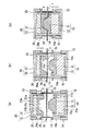
(Match mold forming device with clamp frame)
1 and 2 are schematic cross-sectional views for explaining a first embodiment of a molding method and a molding apparatus using a clamp frame. Although the molding method differs between FIG. 1 and FIG. 2, the same molding apparatus is used. This molding apparatus is an apparatus for molding a sheet by heat-plasticizing at least a part of a thermoforming sheet and then bringing a pair of molds into contact with both sides of the plasticized part. A frame-like clamp frame that clamps the entire circumference of the part is provided around each mold, and the clamp frame is relatively movable with respect to the mold.
図1および図2において符号1は熱成形用積層シートを表す。本発明で用いられる成形装置は、一方のマッチモールド成形用金型としての雄型10および雌型20と、それぞれの金型10,20が固定される固定板13,23と、熱成形用積層シート1の金型成形すべき部分2の周囲全周を両面からクランプする一対のクランプ枠14,24と、クランプ枠を金型に対して駆動する駆動手段としてのシリンダー16,26を備える。
In FIG. 1 and FIG. 2, the code |
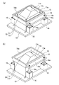
図4に示すように、雄型10は、熱成形用積層シート1に接触して成形体の凹部側の形状を成形する雄型本体11と、雄型本体11を収容するボックス12を備える。雄型本体11の裏面とボックス12の底面との間には、間隙を埋めるためブロック12a(図1および図2参照)が挿入されており、ボックス12は固定板13に固定されている。雄型本体11は、外周部に設けられた水平面11aと、雄型本体11の中央部に設けられた天面11cと、水平面11aおよび天面11cの間をつなぐ斜面11bとを有し、斜面11bおよび天面11cは、水平面11aより高い位置にある。この雄型10には、金型の温度を調節するため、内部に水や油等の媒体の流路(図示せず)が設けてあり、金型温度調節機と接続することができるが、金型の温度調節方法としては特に限定されず、前記手法以外でも構わない。
雄型10の水平面11aと斜面11bの接合部には、必要に応じて、エアー抜き穴や真空孔(不図示)を設けてもよい。これらの孔は、成形体に跡が残らないよう、なるべく小さいほうが好ましい。孔の直径は、具体的には、直径0.3〜1.2mmの範囲内が好ましく、0.3〜0.6mmの範囲がより好ましい。
As shown in FIG. 4, the
An air vent hole or a vacuum hole (not shown) may be provided at the joint between the
雄型10の周囲には、枠状のクランプ枠14が設けられている。クランプ枠14の両側部には一対の張出部14aが外側に突設されており、この張出部14aには、シリンダー16の駆動軸(ロッド)16aの先端が固定されている。これにより、クランプ枠14は雄型10に対して相対的に移動自在に構成されている。図4(a)は、クランプ枠14を雄型10に対して下げた状態を、図4(b)はクランプ枠14を雄型10に対して上げた状態を示す。クランプ枠14を駆動するシリンダー16は、雄型10のボックス12と共通の固定板13に固定されている。このため、固定板13を不図示の駆動手段で駆動させることにより、熱成形用積層シート1に対して雄型10とクランプ枠14との両方を同時に近づけ、また遠ざけることができる。
A frame-shaped
図5に示すように、雌型20は、熱成形用積層シート1に接触して成形体の凸部側の形状を成形する雌型本体21と、雌型本体21を収容するボックス22を備える。雌型本体21の裏面とボックス22の底面との間には、間隙を埋めるためブロック22a(図1および図2参照)が挿入されており、ボックス22は固定板23に固定されている。雌型本体21は、外周部に設けられた水平面21aと、雌型本体21の中央部に設けられた底面21cと、水平面21aおよび底面21cの間をつなぐ斜面21bとを有し、斜面21bおよび底面21cは、水平面21aより低い位置にある。この雌型20には、金型の温度を調節するため、内部に水や油等の媒体の流路(図示せず)が設けてあり、金型温度調節機と接続することができるが、金型の温度調節方法としては特に限定されず、前記手法以外でも構わない。
雌型20の斜面21bと底面21cの接合部には、必要に応じて、エアー抜き穴や真空孔(不図示)を設けてもよい。これらの孔は、成形体に跡が残らないよう、なるべく小さいほうが好ましい。孔の直径は、具体的には、直径0.3〜1.2mmの範囲内が好ましく、0.3〜0.6mmの範囲がより好ましい。
As shown in FIG. 5, the
An air vent hole or a vacuum hole (not shown) may be provided at the joint between the
雌型20の周囲には、枠状のクランプ枠24が設けられている。クランプ枠24の両側部には一対の張出部24aが外側に突設されており、この張出部24aには、シリンダー26の駆動軸(ロッド)26aの先端が固定されている。これにより、クランプ枠24は雌型20に対して相対的に移動自在に構成されている。図5(a)は、クランプ枠24を雌型20に対して下げた状態を、図5(b)はクランプ枠24を雌型20に対して上げた状態を示す。クランプ枠24を駆動するシリンダー26は、雌型20のボックス22と共通の固定板23に固定されている。このため、固定板23を不図示の駆動手段で駆動させることにより、熱成形用積層シート1に対して雌型20とクランプ枠24との両方を同時に近づけ、また遠ざけることができる。
A frame-shaped
マッチモールド成形においては、雄型10の表面形状と雌型20の表面形状を同形状とする。ただし、雄型10と雌型20を合わせた際の両金型間のクリアランスは、使用する熱成形用積層シート1の厚みおよび熱成形時の展開率を考慮して適切に調整する必要がある。具体的には、雄型10と雌型20とのクリアランスは、実際に得られる三次元成形体の厚み分布に対して−50〜+30%の範囲内にすることが好ましく、より好ましくは、−30〜+10%の範囲内で設計すると良い。金型間のクリアランスが大きすぎると、熱成形時に両金型でシートを挟み込むことができなくなり、得られる成形体の型再現性が悪くなると共に、冷却ムラにより該成形体の変形が大きくなる。逆に、前記クリアランスが小さすぎると成形体に圧迫痕及び真空孔痕が残りやすくなる。特に、熱成形用積層シート1として意匠性を有する加飾シートを用いる場合、前記クリアランスを適切にすることで、成形時の意匠性の変化が小さくなり、目的とする意匠性を有する成形体が得やすくなる。
また、金型を加温して用いる場合は、金型の熱膨張率を考慮して金型設計(特に、クリアランス調整)を行う必要がある。
In the match mold molding, the surface shape of the
Further, when the mold is heated and used, it is necessary to perform mold design (particularly clearance adjustment) in consideration of the coefficient of thermal expansion of the mold.
本発明において、金型10,20の具体的な形状や寸法は、成形体の形状や寸法によって適宜設計が可能であり、また熱成形用積層シート1の熱成形性に依存するため、特に限定されるものではないが、十分な型再現性を有する三次元成形体を得るためには、金型のコーナー部のR値は0.2mm以上、展開率は500%以内、最大絞り比(最大高さ/底部の最低長さ)が1.5以下、最大傾斜角度87°以内が好ましい。さらに好ましくは、コーナー部のR値が0.5mm以上、展開率が350%以内、最大絞り比が1.0以下、最大傾斜角度が85°以内である。
In the present invention, the specific shapes and dimensions of the
本発明は、熱成形用積層シート1を成形するための雄型10および雌型20に加えて、可動式のクランプ枠14,24を併用することにより、マッチモールド成形特有の問題である成形皺の発生(これは金型内へのシート引き込みにより発生する。)を効果的に抑制することができる。また、低温成形時のシート弛みによる成形皺の発生も同時に抑制することができる。
In the present invention, in addition to the
可動式クランプ枠14,24は、可動式ゆえに加熱後にシート1をクランプすることができるため、熱成形用積層シート1を強力に固定することが可能で、金型10,20内へのシート1の引き込みによる成形皺を著しく抑制することができる。汎用の連続成形機では、加熱時のシート固定方法として枠状クランプを用いる場合は少なく、また、枠状クランプを使用する場合であっても、加熱前にシートをクランプするため、シート固定力が不十分であった。また、熱可塑性樹脂からなるシート1は、一般的にガラス転移温度以下では熱膨張によりシートが弛みやすく、この弛みにより成形皺が発生するという問題があるが、本発明の特徴的要素である可動式クランプ枠14,24を用いれば、加熱後の熱成形用積層シート1をクランプ枠14,24で保持したまま雄型10または雌型20に押し当てることにより、成形前(雌型20と雄型10の勘合前)の皺を除去することができる。
可動式クランプ枠14,24の構造としては、加熱後にシート1を固定でき、かつ、可動時に雄型10及び雌型20とぶつからない形状が好ましい。具体的には、可動式クランプ枠14,24とボックス12,22(ボックスが無い場合、雄型10及び雌型20)との距離は、シートの性状および厚みに依存するため限定されないが、成形前の皺を効果的に抑制できることから、シート厚みより大きく20mm以下の範囲内が好ましい。
Since the movable clamp frames 14 and 24 are movable and can clamp the
As the structure of the movable clamp frames 14 and 24, a shape that can fix the
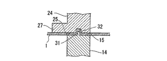
クランプ枠14,24は、熱成形用積層シート1をクランプするシート固定部15,25の面上に、例えば図7に示すように、互いに嵌合する凸部31と凹部32との組み合わせを有することが好ましい。これにより、熱成形用積層シート1を両クランプ枠14,24間にクランプしたときに、一方のクランプ枠に突設された凸部31を他方のクランプ枠に凹設された凹部32に嵌入させ、熱成形用積層シート1をより強力に固定できる。これら凸部31及び凹部32の組み合わせ方としては、雄型側クランプ枠14に凸部31、雌型側クランプ枠24に凹部32を設けるのでもよく、逆に、雄型側クランプ枠14に凹部32、雌型側クランプ枠24に凸部31を設けるのでもよく、これらを併用してもよい。
凸部31および凹部32の形状は特に限定されるものではなく、凸部31としては、ピン状、リブ状、鋸歯状、山形、三角形状、柱状など各種形状を採用可能である。また凹部32としては溝、底を有する穴、貫通穴など各種形状を採用可能である。クランプ時、凸部31と凹部32で熱成形用積層シート1を挟み込む形態でもよいし、熱成形用積層シート1を食い破って穴を開ける形態でもよい。
The clamp frames 14 and 24 have a combination of a
The shape of the
クランプ枠14,24の可動方向は、特に限定されないが、金型10,20の水平面11a,21aに対して垂直な上下方向であることが、シート1の張りを金型に接触させる圧力によって調節することが可能になり、成形皺を効果的に抑制できる上、コスト的に有利であることから好ましい。また、クランプ枠14,24を可動させる動力についても、特に限定されないが、空気圧または油圧を用いたシリンダー16,26を用いる方式が簡便であることから好ましく、とりわけ空気圧式シリンダー(以下、エアーシリンダーと示す。)のほうが実行速度が速いためより好ましい。また、シリンダーを用いる場合、シートのクランプ力が均一となることから、シリンダーを2個以上使用することが好ましく、4個以上の使用がより好ましい。
The movable direction of the clamp frames 14 and 24 is not particularly limited, but the vertical direction perpendicular to the
クランプ枠14,24を用いて成形用シートを固定するクランプ力は、熱成形用積層シート1の性状およびクランプ枠の形状によるため限定されないが、マッチモールド成形時の金型内へのシート引き込みによる皺不良を良好に抑制できることから5kgf{約50N}以上が好ましい。また、クランプ応力としては0.05kgf/cm2{約5kPa}以上が好ましい。
Clamping force for fixing the molding sheet using the clamp frames 14 and 24 is not limited because it depends on the properties of the thermoforming laminated
本発明の金型10,20及び可動式クランプ枠14,24の材質は、特に限定されず、従来マッチモールド成形用金型に使用される各種金属等を用いることができる。具体的には、アルミニウム系鋼材、鉄系鋼材、熱硬化樹脂等が挙げられ、特に、金型の材料としては硬質アルミニウム鋼材が好ましい。また、必要に応じて、研磨処理、フッ素樹脂処理、アルマイト処理、窒化処理、硼化処理、メッキ処理等の表面処理を施すこともできる。
The materials of the
本発明に係るマッチモールド成形用金型及び成形方法は、シート加熱装置、下型可動装置、上型可動装置が具備されている各種成形機で用いることができるが、操作性の観点から、真空成形機(プラグ機構付き)若しくは真空圧空成形機が好ましい。シート加熱装置としては、シート表面に加熱装置の痕が残らないことから、シートの片面若しくは両面からの間接加熱方式が好ましい。また、多様な成形方法が可能となることから、下型可動装置及び上型可動装置の少なくとも一方に真空機構が具備されていることが好ましい。また、真空機構を有する可動装置の一方の可動装置には、圧空機構が具備されていても良い。また、下型可動装置及び上型可動装置の駆動方式は特に限定されず、エアーシリンダー式、油圧シリンダー式、サーボモーター式等を用いることができる。ただし、下型と上型の型閉力は、熱成形用積層シート1の性状および金型形状に依存するため限定されないが、10kgf{約100N}以上必要であり、型再現性が良好となることから、100kgf以上{約1kN以上}であることがより好ましい。また、型閉応力としては、0.05kgf/cm2{約5kPa}以上が好ましい。なお、ここで言う型閉力とは、雌型と雄型とを勘合する際の最大圧縮力を示す。具体的には、下型可動装置及び上型可動装置の最大推力の小さいほうから、雌型用及び雄型用の可動式クランプ枠の最大推力の大きいほうを差し引いた推力を示す。
The match mold molding die and molding method according to the present invention can be used in various molding machines equipped with a sheet heating device, a lower mold movable device, and an upper mold movable device. A molding machine (with a plug mechanism) or a vacuum / pressure forming machine is preferred. As the sheet heating device, an indirect heating method from one side or both sides of the sheet is preferable because no trace of the heating device remains on the sheet surface. Moreover, since various molding methods are possible, it is preferable that a vacuum mechanism is provided in at least one of the lower mold movable device and the upper mold movable device. One of the movable devices having a vacuum mechanism may be provided with a pressure air mechanism. Moreover, the drive system of a lower mold | type movable apparatus and an upper mold | type movable apparatus is not specifically limited, An air cylinder type, a hydraulic cylinder type, a servo motor type, etc. can be used. However, the mold closing force of the lower mold and the upper mold is not limited because it depends on the properties of the thermoforming laminated
すなわち、本発明のクランプ枠を有する成形装置を用いれば、下型可動装置、上型可動装置、雌型用可動式クランプ枠及び雄型用可動式クランプ枠の推力の調整により、シートのクランプ力、成形速度、型閉力を自在に選択することができる。例えば、可動式クランプ枠の推力を高くすると、シートのクランプ力が高く、成形速度が遅く、型閉力が低くなり、逆に、可動式クランプ枠の推力を低くすると、シートのクランプ力が低く、成形速度が速く、型閉力が高くなる。 That is, if the molding apparatus having the clamp frame of the present invention is used, the clamping force of the sheet is adjusted by adjusting the thrust of the lower mold movable apparatus, the upper mold movable apparatus, the female mold movable clamp frame, and the male mold movable clamp frame. The molding speed and the mold closing force can be freely selected. For example, if the thrust of the movable clamp frame is increased, the clamping force of the sheet is high, the forming speed is slow, and the mold closing force is low. Conversely, if the thrust of the movable clamp frame is low, the clamping force of the sheet is low. The molding speed is fast and the mold closing force is high.
本発明に係る成形方法としては、以下の(1)ないし(9)の手順によるマッチモールド成形を用いることが好ましい。
(1) 熱成形用積層シート1を成形機付属のクランプ(不図示)で固定する。
(2) ヒーター(不図示)を該シート1の上方および/または下方の位置へ移動させる。
(3) 該シート1を所定温度になるまで前記ヒーターで加熱する。
(4) 前記ヒーターを成形機外に退避させる。
(4′) 加熱位置と成形位置が異なる場合は、加熱されたシートを金型位置まで移動させる。
(5) シート1の上側に配置した雌型20を下降させ、シート1の下側に配置した雄型10を上昇させる。
(6) 熱成形用積層シート1を両面からクランプ枠14,24によりクランプした後、雌型20の下降及び雄型10の上昇を利用して、そのまま雌型20と雄型10でシート1を挟み込むようにして三次元形状とする、
(7)雌型20と雄型10で該シート1を挟み込んだまま所定時間保持する。
(8)雌型20を上昇、雄型10を下降させ、三次元形状とした成形体を両金型10,20および両クランプ枠14,24から離した後、該成形体をエアー等で所定時間冷却する。
(9)成形機付属のクランプを開放する。
As the molding method according to the present invention, it is preferable to use match mold molding according to the following procedures (1) to (9).
(1) The
(2) The heater (not shown) is moved to a position above and / or below the
(3) The
(4) The heater is moved out of the molding machine.
(4 ′) When the heating position and the molding position are different, the heated sheet is moved to the mold position.
(5) The
(6) After the
(7) Hold the
(8) The
(9) Open the clamp attached to the molding machine.
(6)において、シートをクランプするときにシートが金型と接していないほうが、シート伸びが均等になりやすいため好ましい。
(2)〜(4)において、シリンダー16,26の上昇及び下降の動作を手動又は電磁弁の操作によりクランプ枠14,24の高さを調節し、作動時のクランプ枠14,24とヒーターとの接触を回避することができる。
なお、上記手順(2)に代えて、該シート1を金型10,20間から退避させて、成形機外に設置したヒータ(不図示)の位置まで移動させても構わない。この場合、上記手順(4)に代えて、該シート1を成形機外から金型10,20間の位置に移動させる。
また、(8)において、シリンダー16の作動により離型速度が早くなり、成形体と雄型との離型性が劣る場合は、シリンダー16の作動を手動又は電磁弁操作により開放した上で雌型を下降させれば良い。
また、シート1上側に雄型10、シート1下側に雌型20を配置することも可能である。この場合、手順(5),(6)では雄型10を下降、雌型20を上昇させ、手順(8)では雄型10を上昇、雌型20を下降させる。
In (6), when the sheet is clamped, it is preferable that the sheet is not in contact with the mold because the sheet elongation tends to be uniform.
In (2) to (4), the heights of the clamp frames 14 and 24 are adjusted manually or by operating the solenoid valves to move the
Instead of the procedure (2), the
In (8), when the release speed between the molded body and the male mold is inferior due to the operation of the
It is also possible to arrange the
手順(6)において、可動式クランプ枠14,24の形状選択および推力調整により、以下の2通りの成形法A,Bを選択することができる。いずれの成形法を適用することも可能であり、金型デザインやシート構成等を考慮して、より適正な方法を選択するのが望ましい。 In step (6), the following two molding methods A and B can be selected by selecting the shape of the movable clamp frames 14 and 24 and adjusting the thrust. Any molding method can be applied, and it is desirable to select a more appropriate method in consideration of a mold design, a sheet configuration, and the like.
(成形法A)
図1(a)に示すように、熱成形用積層シート1を両面からクランプ枠14,24によりクランプした後、図1(b)に示すように、雌型側クランプ枠24の下降推力を雄型側クランプ枠14の上昇推力より小さくすることにより、加熱後に可動式クランプ枠14,24により固定された熱成形用積層シート1を、先に雌型20に押し当てる。すなわち、雌型20の水平面21aを熱成形用積層シート1の中央部に押し当て、熱成形用積層シート1の金型成形すべき部分2を雄型10側に突出させる。これにより、熱成形用積層シート1には、雌型20の水平面21aに接触した部分と、クランプ枠14,24でクランプされた部分との間で段差を生じさせてシート1の皺を伸ばすことができる。しかるのち、図1(c)に示すように、雄型10と雌型20とでシート1を挟み込んで三次元形状に成形する。
(Forming method A)
As shown in FIG. 1A, after the thermoforming laminated
図1(b)において、雌型20の水平面21aと、雌型側クランプ枠24がシート1をクランプする面25との間の高低差は、熱成形用積層シート1の性状および金型形状に依るため特に限定されないが、低温成形時のシート弛みを効果的に除去できることから2〜30mmの範囲内が好ましい。なお、前記高低差の符号は、雌型20の水平面21aが雌型側クランプ枠24のクランプ面25より雄型10側に突出している場合を正とする。
この成形法Aによれば、装飾層を有する加飾シートを用いる場合、該装飾層が可視となる意匠面を雌型20側に向けることにより、装飾鮮鋭性が良好な成形体が得やすい。さらに、印刷柄を装飾層として有する加飾シートを用いて、得られる成形体を部分的に加飾する場合、図柄位置を合わせやすく、また、成形時の偏肉が起こりにくいため、図柄自体の不均一変形も少なくなる。
また、雌型20が下側、雄型10が上側であっても同様である。
In FIG. 1B, the difference in height between the
According to this forming method A, when a decorative sheet having a decorative layer is used, it is easy to obtain a molded article with good decorative sharpness by directing the design surface on which the decorative layer becomes visible toward the
The same applies to the
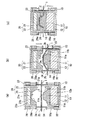
(成形法B)
図2(a)に示すように、熱成形用積層シート1を両面からクランプ枠14,24によりクランプした後、図2(b)に示すように、雌型側クランプ枠24の下降推力を雄型側クランプ枠14の上昇推力より大きくすることにより、加熱後に可動式クランプ枠14,24により固定された熱成形用積層シート1を、先に雄型10に押し当てる。すなわち、雄型10の天面11cを熱成形用積層シート1の中央部に押し当て、熱成形用積層シート1の金型成形すべき部分2を雌型20側に突出させる。これにより、熱成形用積層シート1には、雄型10の天面11cに接触した部分2aと、クランプ枠14,24でクランプされた部分との間で段差を生じさせてシート1の皺を伸ばすことができる。しかるのち、図2(c)に示すように、雄型10と雌型20とでシート1を挟み込んで三次元形状に成形する。
(Forming method B)
As shown in FIG. 2A, after the thermoforming laminated
図2(b)において、雄型10の水平面11aと、雄型側クランプ枠14がシート1をクランプする面15との間の高低差は、熱成形用積層シート1の性状および金型形状に依存するため特に限定されないが、低温成形時のシート弛みを効果的に除去できることから−30〜15mmの範囲内が好ましい。なお、前記高低差の符号は、雄型10の水平面11aが雄型側クランプ枠14のクランプ面15より雌型20側に突出している場合を正とし、前記水平面11aが前記クランプ面15より低い位置にある場合を負とする。図2(b)に示す例では、雄型10の水平面11aと雄型側クランプ枠14のクランプ面15とがほぼ同一面上にあり、前記高低差はほぼ0mmである。また、雄型側クランプ枠14がシート1をクランプする面15との間の高低差を0mm未満とし、且つ、雄型に設けた真空孔から真空吸引することにより、型再現性がさらに良好となる場合がある。
In FIG. 2B, the difference in height between the
この成形法Bによれば、雄型10の天面11cとクランプ枠14,24との間でシート1(金型に接触していない部分2b)は雄型10の斜面11bにも水平面11aにも接触させずに伸長させることができるので、成形体の勾配部(金型10,20の斜面11b,21bによって成形される部分)により多くの面積のシートを配分することができる。よって、展開率の高い部分や勾配の大きい部分を有するような形状の金型を用いる場合に、型再現性が良好な成形体が得やすい。なお、雌型20が下側、雄型10が上側であっても同様である。
According to this forming method B, the sheet 1 (
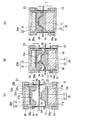
次に、本発明の成形方法および成形装置の第2形態例を説明する。
図3は、本発明の成形方法および成形装置の第2形態例を説明する模式的断面図である。図6は、図3で用いられるクランプ枠を設けた雌型を示す斜視図である。
本形態例では、雄型10および雄型側クランプ枠14としては、上記第1形態例と同様に、図4に示すものを用いることができる。雌型側クランプ枠24としては、図3および図6に示すように、クランプ枠24の内周縁部にフランジ部27が延びており、該フランジ部27が雄型側クランプ枠14の内周縁部よりも内側にあるクランプ枠を用いる。この場合、雌型20Aとしては、雌型本体21の水平面21aの高さがフランジ部27の厚み以上に、ボックス22の端縁より突出しているものを用いる。雌型本体21の高さを調節する方法としては、雌型本体21の裏側に高さ調節用のプレート22bを挿入する方法があり、この方法によれば、図5の雌型20のボックス22内にプレート22bを追加するだけで図6の雌型20Aを構成することができる。
Next, a second embodiment of the molding method and molding apparatus of the present invention will be described.
FIG. 3 is a schematic cross-sectional view for explaining a second embodiment of the molding method and molding apparatus of the present invention. FIG. 6 is a perspective view showing a female mold provided with a clamp frame used in FIG. 3.
In the present embodiment, the
本形態例におけるクランプ枠14,24は、第1形態例の成形装置で述べたのと同様に、熱成形用積層シート1をクランプするシート固定部15,25の面上に互いに嵌合する凸部31と凹部32との組み合わせ(図8,図9参照)を有することが好ましい。これにより、熱成形用積層シート1を両クランプ枠14,24間にクランプしたときに、一方のクランプ枠に突設された凸部31を他方のクランプ枠に凹設された凹部32に嵌入させ、熱成形用積層シート1をより強力に固定できる。これら凸部31及び凹部32の組み合わせ方としては、雄型側クランプ枠14に凸部31、雌型側クランプ枠24に凹部32を設けるのでもよく、雄型側クランプ枠14に凹部32、雌型側クランプ枠24に凸部31を設けるのでもよく、これらを併用してもよい。
The clamp frames 14 and 24 in the present embodiment are projections that fit together on the surfaces of the
本形態例においては、上述の成形法B(シートに対して先に雄型を押し当てる)と同様の方法によりシート1の成形ができる。すなわち、図3(a)に示すように、熱成形用積層シート1を両面からクランプ枠14,24によりクランプした後、図3(b)に示すように、雌型側クランプ枠24のクランプ圧力を雄型側クランプ枠14のクランプ圧力より大きくすることにより、加熱後に可動式クランプ枠14,24により固定された熱成形用積層シート1を、先に雄型10に押し当てる。すなわち、雄型10の天面11cを熱成形用積層シート1の中央部に押し当て、熱成形用積層シート1の金型成形すべき部分2を雌型20A側に突出させる。これにより、熱成形用積層シート1には、雄型10の天面11cに接触した部分2aと、クランプ枠14,24でクランプされた部分との間で段差を生じさせて皺を伸ばすことができる。しかるのち、図3(c)に示すように、雄型10と雌型20Aとでシート1を挟み込んで三次元形状に成形する。
In this embodiment, the
さらに、図3(b)の段階において、加熱後に可動式クランプ枠14,24により固定された熱成形用積層シート1を、先に雄型10に押し当てたとき、雌型側クランプ枠24の内周縁部のフランジ部27と雄型10の外周縁部17(ここではボックス12の端縁)との間で熱成形用積層シート1をクランプし、さらに、雄型10の裾部(水平面11aと斜面11bの接合部)に設けた真空孔18(図3(b)参照)より、熱成形用積層シート1の加熱可塑化した部分2を雄型10側から真空吸引する。
この構成によれば、雄型側の真空を効果的に使用することができるため、さらに型再現性良好な成形体が得やすい。真空吸引の際、雄型10の凸部とフランジ部27との間隔(図3(b)において水平方向の間隔)は、皺発生が抑制できるとともに、型再現性が更に良好となることから、5〜50mmが好ましい。また、フランジ部27の形状としては、雄型10の凸部とフランジ部27との間隔が均一である必要はなく、展開率が高い部分の間隔を意図的に長くしたり、ブリッジ不良が発生しやすい部分の間隔を意図的に短くしたりすれば、意匠保持性および型再現性を更に良好にすることができる。
3B, when the thermoformed
According to this configuration, since the vacuum on the male mold side can be used effectively, it is easy to obtain a molded article with better mold reproducibility. At the time of vacuum suction, the distance between the convex part of the
なお、熱成形の装置及び方法は、上述のマッチモールド成形に限定されるものではなく、圧空真空成形、圧空成形、真空成形、等を利用することもできる。圧空成形や真空成形の場合、金型は雄型と雌型のうち片方の金型のみを使用して成形を行うことも可能である。 Note that the thermoforming apparatus and method are not limited to the above-described match mold molding, and pressure-vacuum vacuum molding, pressure-air molding, vacuum molding, and the like can also be used. In the case of pressure forming or vacuum forming, the mold can be formed using only one of a male mold and a female mold.
(熱成形の温度条件)
成形時の熱成形用積層シートの温度は、原反として使用する熱成形用積層シートの熱成形性および金型形状に依存するため特に限定されないが、意匠性を有する加飾シートを用いる場合、低温で成形するほど意匠性変化が少なく、装飾鮮鋭性の優れた成形体が得やすく、特に、金属光沢性加飾シートの場合に高光沢性の成形体が得られることから好ましい。さらに、成形体の部分加飾を目的とした印刷柄を装飾層として有する加飾シートの場合に図柄合わせしやすいことから好ましい。
(Temperature conditions for thermoforming)
The temperature of the laminated sheet for thermoforming at the time of molding is not particularly limited because it depends on the thermoformability and mold shape of the laminated sheet for thermoforming used as a raw fabric, but when using a decorative sheet having design properties, As the molding is performed at a lower temperature, the change in the design property is less, and a molded article having excellent decorative sharpness can be easily obtained. In particular, a highly glossy molded article is obtained in the case of a metallic glossy decorative sheet. Furthermore, it is preferable because it is easy to match the pattern in the case of a decorative sheet having a printed pattern for the purpose of partial decoration of the molded body as a decorative layer.
具体的には、少なくとも、熱可塑性フィルム層(A)と、接着剤層(D)と、前記接着剤層(D)に接触する側の面は平滑でありその反対面にはエンボスロールにより凹凸模様が転写された支持基材層(C)とがこの順に積層された熱成形用積層シートを熱成形する場合の成形温度は、(T1−20)℃以上(T2)℃以下の温度範囲であることが好ましい。
ただしT1は熱可塑性フィルム層(A)と支持基材層(C)を一体化した積層シートの軟化温度であり、T2は支持基材層(C)の軟化温度である。ただし、ここでいう軟化温度とは、JIS K7244−1法に準拠して測定される動的粘弾性測定を用いて、周波数1Hz、昇温速度3℃/分の測定条件で測定した貯蔵弾性率の温度依存曲線の低温側のベースラインを高温側に延長した直線と、階段状変化部分の曲線の勾配が最大になるような点でひいた接線との交点の温度とする。
また、成形温度が(T1−20)℃以上の条件と(T2)℃以下の条件とを両方満足するためには、T1とT2とが、(T1−20)℃≦(T2)℃の関係となる必要がある。
Specifically, at least the thermoplastic film layer (A), the adhesive layer (D), and the surface in contact with the adhesive layer (D) are smooth, and the opposite surface is uneven by an embossing roll. The molding temperature in the case of thermoforming the laminated sheet for thermoforming in which the support base material layer (C) to which the pattern is transferred is laminated in this order is in a temperature range of (T1-20) ° C. or more and (T2) ° C. or less. Preferably there is.
However, T1 is the softening temperature of the laminated sheet which integrated the thermoplastic film layer (A) and the support base material layer (C), and T2 is the softening temperature of the support base material layer (C). However, the softening temperature here refers to a storage elastic modulus measured under measurement conditions of a frequency of 1 Hz and a heating rate of 3 ° C./min using dynamic viscoelasticity measurement measured in accordance with JIS K7244-1 method. The temperature at the intersection of the straight line obtained by extending the base line on the low temperature side of the temperature dependence curve to the high temperature side and the tangent line drawn at the point where the slope of the step-like change portion becomes the maximum.
Further, in order to satisfy both the conditions where the molding temperature is (T1-20) ° C. or higher and the conditions (T2) ° C. or lower, the relationship of T1 and T2 is (T1-20) ° C. ≦ (T2) ° C. It is necessary to become.
すなわち本発明においては、熱可塑性フィルムが十分展延する温度である(T1−20)℃を下限とし、エンボス模様が消えない温度(T2)℃を上限とする温度範囲で熱成形することにより、支持基材層(C)の凹凸模様が熱可塑性フィルム層(A)側(意匠面側)に浮き上がらせ、意匠面側から凹凸模様を認識可能な成形体を製造することができる。すなわち、上述の温度範囲の成形温度で熱成形を行うことにより、型再現性と意匠性とが共に良好な成形体を製造できるため好ましい。
より好ましい成形温度の範囲は、(T1−15)℃以上(T2−5)℃以下の範囲であり、さらに好ましい成形温度の範囲は、(T1−10)℃以上(T2−10)℃以下の範囲である。
That is, in the present invention, by thermoforming in a temperature range in which the temperature at which the thermoplastic film is sufficiently spread (T1-20) ° C. is the lower limit and the temperature at which the embossed pattern does not disappear (T2) ° C. is the upper limit, The uneven | corrugated pattern of a support base material layer (C) can float on the thermoplastic film layer (A) side (design surface side), and the molded object which can recognize a concavo-convex pattern from the design surface side can be manufactured. That is, it is preferable to perform thermoforming at a molding temperature in the above-described temperature range because a molded product having both good mold reproducibility and design can be manufactured.
A more preferable molding temperature range is (T1-15) ° C. or more and (T2-5) ° C. or less, and a more preferable molding temperature range is (T1-10) ° C. or more and (T2-10) ° C. or less. It is a range.
さらに具体的には、遠赤外線ヒーターを用いた場合、ヒーター温度で200〜500℃、間接加熱時間を5〜30秒とし、該シートが熱成形可能となる温度とすることが好ましい。また、金型温度については、得られる成形体の外観や成形収縮率を確認しながら決める必要があるが、これを20〜200℃とし、雄型と雌型とでシートを挟み込む時間(前記の工程(7)に該当する。)は10秒〜5分とすることが好ましい。また、金型温度は、熱成形用積層シート1の性状によるため特に限定されず、得られる成形体の外観、型再現性、成形収縮率および変形具合によって適宜調整すれば良い。例えば、2つの金型との間に必要に応じて温度勾配を設けても良い。また、熱成形終了後、得られた成形体をエアー等で冷却することが好ましい。
More specifically, when a far-infrared heater is used, the heater temperature is preferably 200 to 500 ° C., the indirect heating time is 5 to 30 seconds, and the temperature at which the sheet can be thermoformed is preferable. Further, the mold temperature needs to be determined while confirming the appearance and molding shrinkage of the molded body to be obtained. This is set to 20 to 200 ° C., and the time for sandwiching the sheet between the male mold and the female mold (described above) The step (7) corresponds to 10 seconds to 5 minutes. The mold temperature is not particularly limited because it depends on the properties of the thermoformed
上述の装飾層を有する積層シートにおいて、どちらの面から金型に接触させるかは特に限定はないが、熱可塑性フィルム層(A)(装飾層(B)が可視となる意匠面の側)から金型に接触させると、装飾層(B)の金属薄膜細片の配向が揃った状態を金型によって維持しやすいので、装飾鮮鋭性が良好な成形体が得やすい。また、支持基材層(C)側から変形させた場合、装飾層(B)の変形がマイルドになり、意匠性保持効果が高いと考えられる。一方、型再現性の観点からは、変形し難い(例えば、転移温度が高い)ほうから変形させたほうが良い場合もある。そこで、金型デザインやシート構成等を考慮して、より適正な方法を選択するのが望ましい。 In the laminated sheet having the decorative layer described above, there is no particular limitation as to which surface is brought into contact with the mold, but from the thermoplastic film layer (A) (the side of the design surface where the decorative layer (B) is visible). When brought into contact with the mold, the state in which the orientation of the metal thin film strips of the decoration layer (B) is aligned can be easily maintained by the mold, so that a molded article with good decoration sharpness can be easily obtained. Moreover, when it deform | transforms from the support base material layer (C) side, a deformation | transformation of a decoration layer (B) becomes mild and it is thought that the designability holding effect is high. On the other hand, from the viewpoint of mold reproducibility, it may be better to deform from the one that is less likely to be deformed (for example, the transition temperature is higher). Therefore, it is desirable to select a more appropriate method in consideration of the mold design and the sheet configuration.
〔加飾成形体〕
(インサート射出成形)
高光沢の成形用積層シートを、本発明の熱成形用積層シートの成形方法に従って成形体とした後、得られた成形体と樹脂を一体成形することにより高光沢を有する樹脂との成形体(以下、加飾成形体と言う。)を得ることができる。
加飾成形体は、成形体をその熱可塑性樹脂フィルム側が射出成形金型の雌型に接するように配置し、前記成形体の裏面側に射出樹脂を充填することにより一体成形する方法、若しくは射出金型内で熱成形を行った後、そのまま射出金型内で射出樹脂との一体化を行う方法により作製することができる。いずれも高光沢を有し、破断がなく、型再現性に優れた加飾成形体を得ることができる。
[Decorated molded body]
(Insert injection molding)
A high-gloss laminate sheet is formed into a molded body according to the method for forming a thermoformed laminate sheet of the present invention, and the molded body and resin having high gloss are obtained by integrally molding the obtained molded body and resin ( Hereinafter, it is referred to as a decorative molded body.).
The decorative molded body is a method of integrally molding the molded body by placing the molded body so that the thermoplastic resin film side is in contact with the female mold of the injection mold, and filling the injection resin on the back side of the molded body, or injection After thermoforming in the mold, it can be produced by a method of integrating with the injection resin in the injection mold as it is. Any of them can provide a decorative molded article having high gloss, no breakage, and excellent mold reproducibility.
目的とする射出成形体の形状が二次元形状、若しくは、該シートの最大展開率が120%未満の単純な三次元形状の場合には、該シートを成形体とせず、マッチモールド成形でヘアライン等の模様を付けたシート形状のまま、射出成形金型内に挿入することによりインサート射出成形体とすることができる。 If the shape of the target injection-molded body is a two-dimensional shape or a simple three-dimensional shape with a maximum development rate of less than 120%, the sheet is not used as a molded body, and a hairline or the like is formed by match molding. It is possible to obtain an insert injection molded body by inserting it into an injection mold while keeping the sheet shape with the above pattern.
射出樹脂としては、支持基材層(C)との密着性の観点から、支持基材層(C)と同系統の樹脂が好ましい。具体的には支持基材層(C)がポリプロピレン系樹脂の場合、射出樹脂中にポリプロピレン樹脂が40質量%以上であることが好ましく、50質量%以上であることがより好ましく、60質量%以上であることが更に好ましい。前記射出樹脂がポリプロピレン樹脂を主成分とする場合、該ポリプロピレン樹脂とともに配合可能な他の樹脂としては、本発明の支持基材層(C)を構成するものとして前記に例示した各種熱可塑性樹脂や熱可塑性エラストマー等を好ましく用いることができる。この場合、射出樹脂中に前記ポリプロピレン樹脂を40質量%以上含有し、その他に、一般的にポリプロピレン樹脂と溶融混合可能な各種樹脂を含有しても良い。 The injection resin is preferably a resin of the same system as the support base material layer (C) from the viewpoint of adhesion to the support base material layer (C). Specifically, when the support base layer (C) is a polypropylene resin, the polypropylene resin is preferably 40% by mass or more, more preferably 50% by mass or more, and 60% by mass or more in the injection resin. More preferably. When the injection resin contains a polypropylene resin as a main component, other resins that can be blended together with the polypropylene resin include various thermoplastic resins exemplified above as constituting the support base material layer (C) of the present invention. A thermoplastic elastomer or the like can be preferably used. In this case, the injection resin contains 40% by mass or more of the polypropylene resin, and in addition, various resins that can generally be melt-mixed with the polypropylene resin may be contained.
ポリプロピレン樹脂と溶融混合可能な樹脂としては、高密度ポリエチレン、低密度ポリエチレン、直鎖状低密度ポリエチレン、スチレン−エチレン−ブタジエン−スチレン共重合体及びスチレン−エチレン−プロピレン−スチレン共重合体等のスチレン系エラストマー、エチレン−プロピレン共重合体及びエチレン−プロピレン−ジエン共重合体に代表されるエチレンプロピレンラバー等のオレフィン系エラストマーが挙げられる。支持基材層(C)がABS樹脂の場合には射出樹脂中に40質量%以上のABS樹脂が含まれることが好ましいが、支持基材層(C)の樹脂との接着性が十分であれば、アクリロニトリル/ブタジエン/スチレン(ABS)樹脂、アクリロニトリル/アクリルゴム/スチレン(AAS)樹脂、アクリロニトリル/エチレンゴム/スチレン(AES)樹脂、(メタ)アクリル酸エステル/スチレン(MS)樹脂等を主成分とする樹脂として用いても構わない。 Examples of resins that can be melt-mixed with polypropylene resins include high-density polyethylene, low-density polyethylene, linear low-density polyethylene, styrene-ethylene-butadiene-styrene copolymers, and styrene-ethylene-propylene-styrene copolymers. And olefin elastomers such as ethylene propylene rubber represented by ethylene elastomer, ethylene-propylene copolymer and ethylene-propylene-diene copolymer. When the supporting base layer (C) is an ABS resin, it is preferable that the injection resin contains 40% by mass or more of ABS resin, but the supporting base layer (C) should have sufficient adhesion to the resin. Main components are acrylonitrile / butadiene / styrene (ABS) resin, acrylonitrile / acrylic rubber / styrene (AAS) resin, acrylonitrile / ethylene rubber / styrene (AES) resin, (meth) acrylic ester / styrene (MS) resin It may be used as a resin.
また、前記射出樹脂中には、射出成形体の変形を防ぐ目的で無機フィラーを添加することができる。該無機フィラーとしては、特に限定はされないが、タルク、炭酸カルシウム、クレー、珪藻土、マイカ、珪酸マグネシウム、シリカ等が挙げられる。 An inorganic filler can be added to the injection resin for the purpose of preventing deformation of the injection molded body. The inorganic filler is not particularly limited, and examples thereof include talc, calcium carbonate, clay, diatomaceous earth, mica, magnesium silicate, and silica.
更に、前記射出樹脂中には、低温衝撃性やインモールド成形性が損なわれない範囲で、着色剤、可塑剤、酸化防止剤、紫外線吸収剤、耐電防止剤、難燃剤および滑剤等の添加剤を配合しても良く、これらの添加剤は単独で使用しても2種類以上を併用してもよい。 Further, in the injection resin, additives such as a colorant, a plasticizer, an antioxidant, an ultraviolet absorber, an antistatic agent, a flame retardant, and a lubricant are added as long as the low temperature impact property and the in-mold formability are not impaired. These additives may be used alone or in combination of two or more.
射出樹脂の充填温度は特に限定されるものではないが、樹脂温度が低すぎると支持基材層(C)と射出樹脂が剥がれ易くなり、樹脂温度が高すぎると射出成形体にヒケと呼ばれる反りが発生し易くなる。このため、ポリプロピレン樹脂の場合、射出樹脂の充填温度は180〜270℃が好ましく、200〜260℃がより好ましい。ABS樹脂の場合は200〜290℃が好ましく、210〜260℃がより好ましい。射出金型温度は、雄型と雌型共に20〜100℃とすることが好ましいが、射出成形体に反り等が発生する場合は雄型及び雌型に温度勾配を付けることが必要となる。また、射出金型内に挿入した成形体を、射出樹脂充填前にあらかじめ金型温度まで加温するため、射出遅延時間(型閉めから射出までの時間)を1〜100秒の範囲内で設定しても良い。 The filling temperature of the injection resin is not particularly limited, but if the resin temperature is too low, the supporting base layer (C) and the injection resin are easily peeled off, and if the resin temperature is too high, the injection molded body warps as a sink. Is likely to occur. For this reason, in the case of polypropylene resin, the filling temperature of the injection resin is preferably 180 to 270 ° C, and more preferably 200 to 260 ° C. In the case of an ABS resin, 200 to 290 ° C is preferable, and 210 to 260 ° C is more preferable. The injection mold temperature is preferably 20 to 100 ° C. for both the male mold and the female mold. However, when warpage or the like occurs in the injection molded body, it is necessary to provide a temperature gradient to the male mold and the female mold. In addition, the injection delay time (time from mold closing to injection) is set within the range of 1 to 100 seconds in order to heat the molded body inserted into the injection mold to the mold temperature before filling with the injection resin. You may do it.
以上説明したように、本形態例の成形方法によれば、通常の平滑な金型を使ってシートを三次元形状に熱成形したとき、熱成形用積層シートの支持基材層(C)側の外面(裏面)に形成された凹凸模様が熱可塑性フィルム層(A)側の外面(表面)に浮き出し、支持基材層に付けた凹凸模様が熱可塑性フィルム層の側にハッキリと存在する成形品を製造することができる。これにより、三次元的な形状と表面の凹凸模様を有する成形品を成形することができ、形状と凹凸による視覚的及び触覚的効果が相まって、外観や意匠性に優れる成形品が得られる。装飾層(B)として金属薄膜細片等の金属光沢をもつインキ層と組み合わせると、光の反射により微小な模様(凹凸)まで認識可能となるため、より効果的である。 As described above, according to the molding method of this embodiment, when the sheet is thermoformed into a three-dimensional shape using a normal smooth mold, the support base material layer (C) side of the thermoformed laminated sheet is used. Molding in which the concavo-convex pattern formed on the outer surface (back surface) of the film is raised on the outer surface (front surface) on the thermoplastic film layer (A) side, and the concavo-convex pattern attached to the support base layer is clearly present on the thermoplastic film layer side Product can be manufactured. As a result, a molded product having a three-dimensional shape and a concavo-convex pattern on the surface can be formed, and a molded product excellent in appearance and design can be obtained by combining the visual and tactile effects of the shape and the concavo-convex. When the decorative layer (B) is combined with an ink layer having a metallic luster such as a metal thin film strip, it is more effective because even a minute pattern (unevenness) can be recognized by reflection of light.
熱成形用積層シートの表面(意匠面)側に透明な熱可塑性フィルム層(A)を設けることで高光沢で美麗な意匠が実現できる。熱成形の前には熱可塑性フィルム層(A)の表面は平滑であるから熱可塑性フィルム層(A)に木目調や石目調等の所望の印刷を掛けることも可能である。この印刷模様を、支持基材層(C)側から熱可塑性フィルム層(A)側に浮き上がらせる凹凸模様と組み合わせることで、天然の木目や石目等に近い、よりリアルな触感と意匠表現を付与することも可能になる。 By providing the transparent thermoplastic film layer (A) on the surface (design surface) side of the thermoformed laminated sheet, a high gloss and beautiful design can be realized. Prior to thermoforming, the surface of the thermoplastic film layer (A) is smooth, so that the thermoplastic film layer (A) can be subjected to desired printing such as grain or stone. Combining this printed pattern with a concavo-convex pattern that floats from the support base material layer (C) side to the thermoplastic film layer (A) side gives a more realistic tactile feel and design expression close to natural wood grain or stone grain. It can also be granted.
以下に具体例をもって本発明を説明するが、本発明はこれらに限定されるものではない。なお、実施例及び比較例における物性評価は下記の測定法または試験法にて行った。また、実施例中の「部」及び「%」は、いずれも質量基準によるものとする。 Hereinafter, the present invention will be described with specific examples, but the present invention is not limited thereto. In addition, the physical-property evaluation in an Example and a comparative example was performed with the following measuring method or test method. In the examples, “part” and “%” are both based on mass.
(評価金型)
低面183×204mm、天面51×66mm、高さ50mm、斜面傾斜勾配がそれぞれ35、55、60、70°、天面と斜面の接合部がそれぞれ0.5,1,5,3mmR、斜面同士の接合部が5mmR、斜面と低面の接合部が1mmRの台形形状の雄型10を使用した。また、雌型は雄型と合わせた際のクリアランスが400μmのものを使用した。更に、雄型の水平面(低面)と斜面の接合部には直径0.5mmの真空孔を設け、雌型の底面と斜面の接合部には直径0.5mmのエアー抜き孔を設けた。なお、この金型には成形時のシートズリ込み防止用のため可動式クランプ機構がついている。
(Evaluation mold)
Low surface 183 × 204mm, top surface 51 × 66mm, height 50mm, slope slope gradient is 35, 55, 60, 70 °, respectively, the top and slope joints are 0.5, 1, 5, 3mmR, slope A trapezoidal male die 10 having a joint portion of 5 mmR and a joint portion between the slope and the lower surface of 1 mmR was used. In addition, a female mold having a clearance of 400 μm when combined with the male mold was used. Further, a vacuum hole with a diameter of 0.5 mm was provided at the joint between the male horizontal surface (low surface) and the slope, and an air vent hole with a diameter of 0.5 mm was provided at the joint between the bottom and the slope of the female mold. The mold has a movable clamp mechanism for preventing sheet slippage during molding.
(軟化温度測定方法)
本発明に使用される軟化温度とは、JIS K7244−1法に準拠して測定される動的粘弾性測定を用いて、周波数1Hz、昇温速度3℃/分の測定条件で測定した貯蔵弾性率の温度依存曲線の低温側のベースラインを高温側に延長した直線と、階段状変化部分の曲線の勾配が最大になるような点でひいた接線との交点の温度を軟化温度とした。
(Softening temperature measurement method)
The softening temperature used in the present invention is a storage elasticity measured under dynamic viscoelasticity measurement measured in accordance with JIS K7244-1 method under a measurement condition of a frequency of 1 Hz and a heating rate of 3 ° C./min. The softening temperature was defined as the temperature at the intersection of the straight line obtained by extending the low-temperature base line of the temperature-dependent curve of the rate to the high-temperature side and the tangent line drawn at the point where the slope of the step-like change portion becomes the maximum.
(成形体の外観評価法)
上記評価用金型を用いて作製した成形体を用い、支持基材層(C)由来の凹凸の状態及び展開率180%面における基材本体の破断発生の有無を観察し、以下の基準で評価した。なお、破断は成形体の一部にでも亀裂があった場合は破断と見なした。
◎:破断の発生がなく、光沢が良好でかつハッキリした凹凸がある物。
○:破断の発生はなく、光沢が良好で製品としては充分な凹凸を持つ物。
△:破断の発生はなく、光沢も良好であるが、凹凸が薄く不十分な物。
×:破断の発生が有る、明らかに光沢が低い物、若しくは凹凸が殆ど見られないもの。
(Appearance evaluation method for molded products)
Using the molded body produced using the evaluation mold, the state of unevenness derived from the support base material layer (C) and the presence or absence of breakage of the base material body on the 180% development rate surface were observed. evaluated. Note that the break was regarded as a break when there was a crack in a part of the molded body.
A: No breakage, good gloss and clear irregularities.
○: No breakage, good gloss, and sufficient unevenness as a product.
Δ: No breakage and good gloss, but uneven and thin and insufficient.
X: An occurrence of breakage, apparently low gloss, or almost no unevenness.
(成形体の鏡面性評価法)
成形体の鏡面性評価は、熱成形法による台形状成形体の天面の顔の映り込みを観察し、以下の基準で評価した。
◎:シート本来の鏡面性が十分感じられる物。
○:顔は写るが、鏡面性が十分といえない物。
△:若干鏡面性を感じるが、殆ど顔が写らない物。
×:シルバー調で、全く顔が写らず鏡面性とは言えない物。
(Method for evaluating the specularity of molded products)
The specularity of the molded body was evaluated based on the following criteria by observing the reflection of the top face of the trapezoidal molded body by the thermoforming method.
A: A sheet that can feel the original specularity of the sheet.
○: Face is visible but mirror surface is not sufficient.
Δ: Slightly specular but slightly scary.
X: Silver tone, no face and no specularity.
(鏡面性に優れた熱成形用積層シートの作製)
(A)熱可塑性フィルム層
透明または半透明の熱可塑性フィルム層A−1として、ヘイズ:0.1%、厚さ125μmのゴム変性PMMAフィルム(商品名「テクノロイS−001」、住友化学工業社製、Tg=125℃)を使用した。このシートの軟化温度は112℃であった。
(Production of laminated sheet for thermoforming with excellent specularity)
(A) Thermoplastic film layer As a transparent or translucent thermoplastic film layer A-1, a rubber-modified PMMA film having a haze of 0.1% and a thickness of 125 μm (trade name “Technoloy S-001”, Sumitomo Chemical Co., Ltd.) Manufactured, Tg = 125 ° C.). The softening temperature of this sheet was 112 ° C.
(E)装飾保護層
熱可塑性フィルム層(A)と装飾層(B)の密着性を向上させるため、アクリルポリオール樹脂「6KW−032E」(商品名、大日本インキ化学工業社製、固形分38%(溶剤:酢酸エチル)、水酸基価30KOHmg/g)46部と4−メチル−2−ペンタノン46部との混合溶液に、イソシアヌレート環含有ポリイソシアネート「BURNOCK DN−981」(商品名、大日本インキ化学工業株式会社製、固形分75%(溶剤:酢酸エチル)、官能基数3、NCO濃度14%)8部を混合(合計100部)し、装飾保護層用溶液を調製した。この装飾保護層用溶液は、下記の表面保護層用としても使用する。
(E) Decorative protective layer In order to improve the adhesion between the thermoplastic film layer (A) and the decorative layer (B), an acrylic polyol resin “6KW-032E” (trade name, manufactured by Dainippon Ink and Chemicals, solid content 38 % (Solvent: ethyl acetate), hydroxyl value 30 KOH mg / g) in a mixed solution of 46 parts and 4-methyl-2-pentanone 46 parts, isocyanurate ring-containing polyisocyanate “BURNOCK DN-981” (trade name, Dainippon 8 parts of Ink Chemical Industries, Ltd., solid content 75% (solvent: ethyl acetate), number of functional groups 3,
(F)表面保護層
熱可塑性フィルム層A−1の装飾保護層を積層するのとは反対面に装飾保護層用と同じ塗料を塗工し、層厚み5μmの表面保護層を有する透明または半透明の熱可塑性フィルム層A−2とした。このシートの軟化温度は111℃であった。
(F) Surface protective layer A transparent or semi-coated surface having a surface protective layer having a thickness of 5 μm is applied on the opposite surface of the thermoplastic film layer A-1 from which the decorative protective layer is laminated. It was set as the transparent thermoplastic film layer A-2. The softening temperature of this sheet was 111 ° C.
(B)装飾層
アルミニウム薄膜細片(厚さ0.04μm、面方向の大きさ5〜25μm)を10部、酢酸エチル37.25部、メチルエチルケトン30部、イソプロピルアルコール31.5部、ニトロセルロース1.25部を混合(合計110部)して、アルミニウム薄膜細片スラリーを調製した。
(B)
得られたアルミニウム薄膜細片スラリーを30部、結着樹脂としてカルボン酸含有塩化ビニル−酢酸ビニル樹脂(UCC社製「ビニライトVMCH」)を3部、ウレタン樹脂(荒川化学製「ポリウレタン2593」不揮発分32%)を8部、酢酸エチル23部、4−メチル−2−ペンタノン26部、イソプロピルアルコール10部を混合(合計100部)し、不揮発分中のアルミニウム薄膜細片濃度が35質量%であるインキB−1を調製した。
30 parts of the obtained aluminum thin-film strip slurry, 3 parts of carboxylic acid-containing vinyl chloride-vinyl acetate resin ("Vinylite VMCH" manufactured by UCC) as a binder resin, urethane resin ("Polyurethane 2593" manufactured by Arakawa Chemical)
アルミペースト(不揮発分13%)25部(ハイプリントTD−200T:東洋アルミニウム社製)、ウレタン樹脂(荒川化学社製「ポリウレタン2593」)20部、酢酸エチル27部、メチルエチルケトン18部、イソプロピルアルコール10部を混合し、不揮発分中のアルミニウムペースト濃度が35質量%であるインキB−2を調製した。
25 parts of aluminum paste (non-volatile content: 13%) (Hiprint TD-200T: manufactured by Toyo Aluminum Co., Ltd.), 20 parts of urethane resin (“Polyurethane 2593” manufactured by Arakawa Chemical Co., Ltd.), 27 parts of ethyl acetate, 18 parts of methyl ethyl ketone,
また、インキとは異なるが、熱可塑性フィルム層A−1に真空蒸着法により0.04μmのアルミニウム薄膜を積層させるためのアルミニウムを準備した(B−3として)。 Moreover, although different from ink, the aluminum for laminating | stacking a 0.04 micrometer aluminum thin film by the vacuum evaporation method was prepared for the thermoplastic film layer A-1 (as B-3).
(D)接着剤層
装飾層(B)を有する熱可塑性フィルム層(A)と支持基材層(C)を接着するため、主剤として、芳香族ポリエステルポリオール樹脂「LX−703VL」(商品名、大日本インキ化学工業社製)15部、硬化剤として、脂肪族ポリイソシアネート「KR−90」(商品名、大日本インキ化学工業社製)1部及び希釈剤として、酢酸エチル18部を混合(合計34部)し、ポリエステルウレタン系接着剤を調製した。
(D) Adhesive layer In order to adhere the thermoplastic film layer (A) having the decorative layer (B) and the support base layer (C), as a main agent, an aromatic polyester polyol resin “LX-703VL” (trade name, 15 parts by Dainippon Ink and Chemicals), 1 part of aliphatic polyisocyanate “KR-90” (trade name, manufactured by Dainippon Ink and Chemicals) as a curing agent and 18 parts of ethyl acetate as a diluent ( 34 parts in total) to prepare a polyester urethane adhesive.
(C)支持基材層
支持基材層として住友化学社製低結晶性ポリプロピレン樹脂(エクセレンSP7834)、住友化学社製直鎖状低密度ポリエチレン「FV403」、三井化学社製エチレンプロピレンゴム(タフマー P0480)を70/10/20の割合でドライブレンドした後、押出機ホッパーより投入し、加工温度200℃にてTダイから押出成形し、40℃に加熱されたキャストロールを通した後、巻き取り、300μmの無延伸原反シートC−1を製造した。このシートC−1の軟化温度(T2)は116℃であった。
(C) Support base material layer Low crystalline polypropylene resin (Excellen SP7834) manufactured by Sumitomo Chemical Co., Ltd., linear low density polyethylene “FV403” manufactured by Sumitomo Chemical Co., Ltd., ethylene propylene rubber manufactured by Mitsui Chemicals (Tuffmer P0480) ) Is dry blended at a ratio of 70/10/20, then fed from an extruder hopper, extruded from a T die at a processing temperature of 200 ° C., passed through a cast roll heated to 40 ° C., and wound up An unstretched original fabric sheet C-1 having a thickness of 300 μm was produced. The softening temperature (T2) of this sheet C-1 was 116 ° C.
住友化学社製ブロックPP(ノーブレンAD571)/住友化学社製低密度ポリエチレン(スミカセンF101−1)、三井化学社製エチレンプロピレンゴム(タフマー P0480)を65/15/20の割合でドライブレンドした後、押出機ホッパーより投入し、加工温度230℃にてTダイから押出成形し、40℃に加熱されたキャストロールを通した後、巻き取り、300μmの無延伸原反シートC−2を製造した。このシートC−2の軟化温度(T2)は156℃であった。 After dry blending Sumitomo Chemical's block PP (Noblen AD571) / Sumitomo Chemical's low density polyethylene (Sumikasen F101-1) and Mitsui Chemicals' ethylene propylene rubber (Tuffmer P0480) at a ratio of 65/15/20, After feeding from an extruder hopper, extruded from a T-die at a processing temperature of 230 ° C., passed through a cast roll heated to 40 ° C., wound up, and a 300 μm unstretched original sheet C-2 was produced. The softening temperature (T2) of this sheet C-2 was 156 ° C.
(シートの積層方法)
前記熱可塑性フィルム層(A)に前記装飾保護層用溶液をマイクログラビアコーターを使用し乾燥膜厚2.0μmとなるよう塗工及び乾燥した後、50℃で3日間エージング処理を行った。次に、装飾層(B)として前記インキの場合は前記装飾保護層(E)上にグラビアコーターを使用して乾燥膜厚2.0μmとなるように塗工及び乾燥し、蒸着の場合は真空蒸着法により0.04μmの厚みになるように蒸着を行った。
(Sheet stacking method)
The thermoplastic protective layer (A) was coated and dried with a microgravure coater so that the decorative protective layer solution had a dry film thickness of 2.0 μm, and then subjected to an aging treatment at 50 ° C. for 3 days. Next, in the case of the ink as the decoration layer (B), it is coated and dried on the decoration protective layer (E) using a gravure coater so as to have a dry film thickness of 2.0 μm. Vapor deposition was performed to a thickness of 0.04 μm by a vapor deposition method.
さらに、支持基材層(C)がシートの接着面にぬれ指数40dyne/cmとなるようにコロナ処理を施した後、支持基材層(C)側に前記接着剤をマイクログラビアコーターを用いて乾燥膜厚5μmとなるように塗布・乾燥して得られた接着剤層(D)を、前記ゴム変性PMMAフィルムのインキ塗工面または蒸着面と貼り合わせ、50℃で3日間のエージング処理を行い、熱成形用積層シートを得た。 Furthermore, after the corona treatment was performed so that the supporting base layer (C) had a wetting index of 40 dyne / cm on the adhesive surface of the sheet, the adhesive was applied to the supporting base layer (C) side using a micro gravure coater. The adhesive layer (D) obtained by applying and drying to a dry film thickness of 5 μm is bonded to the ink-coated or vapor-deposited surface of the rubber-modified PMMA film and subjected to aging treatment at 50 ° C. for 3 days. A laminated sheet for thermoforming was obtained.
(成形方法)
(マッチモールド成形)
本実施例のマッチモールド成形には、型締め力10tonの(株)浅野研究所社製小型真空圧空成形機FK−0431−10を用いた。雌型及び雌型用可動式クランプ枠をプラグ可動装置(上側)に、雄型及び雄型用可動式クランプ枠を金型可動装置(下側)に取り付け、以下に示す手順でマッチモールド成形を実施した。
(Molding method)
(Match mold molding)
For the match mold molding of this example, a small vacuum / pressure forming machine FK-0431-10 manufactured by Asano Laboratory Co., Ltd. having a clamping force of 10 ton was used. Attach the female and female movable clamp frames to the plug movable device (upper side) and the male and male movable clamp frames to the mold movable device (lower side). Carried out.
(1)熱成形用積層シートを、熱可塑性フィルム層(A)側が上になるよう成形機付属のクランプで固定する。
(2)上側ヒーターを該熱成形用積層シートの上方へ移動させる(下側ヒーターは不使用)。
(3)該熱成形用積層シートを所定温度になるまで加熱する。
(4)前記ヒーターを退避させる。
(5)雌型を下降、雄型を上昇させる。
(6)雌型の下降及び雄型の上昇を利用して、金型の可動式クランプ枠で該熱成形用積層シートを挟んだ後、そのまま雌型と雄型でシートを挟み込むようにして三次元形状とする。この際、雌型−シート間の空気を逃がす目的で、雌型側からの真空吸引を合わせて行う。
(7)雌型と雄型で該シートを挟み込んだまま1分間保持する。
(8)雌型を上昇、雄型を下降させた後、三次元形状とした成形体をエアーで5秒間冷却する。
(9)成形機付属のクランプを開放する。
以上の(1)〜(9)の工程によりマッチモールド成形法により成形体を得た。
(1) The laminated sheet for thermoforming is fixed with a clamp attached to the molding machine so that the thermoplastic film layer (A) side is on the upper side.
(2) The upper heater is moved above the thermoforming laminated sheet (the lower heater is not used).
(3) The laminated sheet for thermoforming is heated to a predetermined temperature.
(4) Retract the heater.
(5) Lower the female mold and raise the male mold.
(6) Utilizing the lowering of the female mold and the raising of the male mold, the laminated sheet for thermoforming is sandwiched by the movable clamp frame of the mold, and then the sheet is sandwiched between the female mold and the male mold as it is. Use original shape. At this time, vacuum suction from the female mold side is performed for the purpose of releasing air between the female mold and the sheet.
(7) Hold the sheet between the female mold and the male mold for 1 minute.
(8) After raising the female mold and lowering the male mold, the molded body having a three-dimensional shape is cooled with air for 5 seconds.
(9) Open the clamp attached to the molding machine.
A molded body was obtained by the match mold molding method through the above steps (1) to (9).
加熱は、上面のヒーター温度を400℃設定とし、加熱時間の調節により、各実施例及び比較例で示すシート温度までシートを加熱後、成形を行った。なお、ヒーター−シート間距離は130mm、金型温度は雌型が95℃、雄型が75℃、真空・冷却時間は60秒間とした。 For heating, the heater temperature on the upper surface was set to 400 ° C., and the sheet was heated to the sheet temperature shown in each Example and Comparative Example by adjusting the heating time, and then molded. The heater-sheet distance was 130 mm, the mold temperature was 95 ° C. for the female mold, 75 ° C. for the male mold, and the vacuum / cooling time was 60 seconds.
(圧空真空成形、真空成形)
本実施例の圧空真空成形及び真空成形には、型締め力10tonの(株)浅野研究所社製小型真空圧空成形機FK−0431−10を用いた。圧空が金型にうまく伝わるようにマッチモールド金型の雌型キャビティを外し、キャビティを覆っているボックスのみを残してマッチモールド成形と同様の方法で圧空真空成形及び真空成形を実施した。
なお、どちらも雄型側からの真空吸引を行うが、圧空成形時には特に説明がない限りは雌型ボックス側からの圧力を0.4MPaとし、また真空成形時は大気開放状態として成形を行った。
(Pressurized vacuum forming, vacuum forming)
A compact vacuum / pressure forming machine FK-0431-10 manufactured by Asano Laboratories Co., Ltd. having a clamping force of 10 tons was used for the vacuum forming and vacuum forming of this example. The female mold cavity of the match mold was removed so that the compressed air was successfully transmitted to the mold, and the compressed air vacuum forming and vacuum forming were performed in the same manner as the match mold forming except for the box covering the cavity.
In both cases, vacuum suction is performed from the male mold side, but unless otherwise specified, the pressure from the female box side is set to 0.4 MPa, and molding is performed with the atmosphere open during vacuum molding. .
(インサート成形)
熱成形用積層シートを用いて本発明の熱成形より作製した成形体を、インキ層を有するシートの表面保護層が射出成形用金型の雌型に接触するように密着させ金型温度40℃で加熱後、230℃に加熱したノバテック社製ポリプロピレン樹脂(商品名「TX1868H5」)を主原料とした溶融樹脂を金型内に射出して一体成形し、加飾成形体を作製した。なお、射出成形機はファナック社製のオートショット50D、射出成形金型は90mm×100mm×厚さ3mmを用いた。
(Insert molding)
A molded body produced by thermoforming of the present invention using a laminated sheet for thermoforming is brought into close contact so that the surface protective layer of the sheet having the ink layer is in contact with the female mold of the injection mold. After heating, a molten resin made of Novatec polypropylene resin (trade name “TX1868H5”) heated to 230 ° C. as a main raw material was injected into the mold and integrally molded to prepare a decorative molded body. The injection molding machine used was Auto-shot 50D manufactured by FANUC, and the injection mold used was 90 mm × 100 mm × thickness 3 mm.
(実施例1〜8、比較例1〜4)
層構成を、熱可塑性フィルム層(A)/装飾保護層(E)/装飾層(B)/接着剤層(D)/支持基材層(C)とした。このうち支持基材層(C)(表1では「(C)層」と記載。)及び熱可塑性フィルム層(A)(表1では「(A)層」と記載。)は表1に示したシートを使用し425μmの成形用積層シートとした。得られた成形用積層シートを上記の条件でマッチモールド成形法(表1では「マッチ」と記載。)、圧空真空成形法(表1では「圧空」と記載。)及び真空成形法(表1では「真空」と記載。)にて成形体とし成形体の外観評価及び鏡面性の評価を行った。なお、シートの温度はキーエンス社製放射温度計IT2−80で測定を行った。評価結果を表1に示す。
(Examples 1-8, Comparative Examples 1-4)
The layer structure was thermoplastic film layer (A) / decorative protective layer (E) / decorative layer (B) / adhesive layer (D) / support base layer (C). Among these, the supporting base layer (C) (described as “(C) layer” in Table 1) and the thermoplastic film layer (A) (described as “(A) layer” in Table 1) are shown in Table 1. The laminated sheet was formed into a 425 μm molding sheet. The obtained laminated sheet for molding was subjected to the match molding method (described as “Match” in Table 1), the pressure vacuum forming method (described as “Pressure” in Table 1), and the vacuum forming method (Table 1) under the above conditions. Then, it was described as “vacuum”.) The molded body was evaluated for appearance and specularity. In addition, the temperature of the sheet | seat was measured with Keyence Corporation radiation thermometer IT2-80. The evaluation results are shown in Table 1.

実施例8は、装飾層として、金属蒸着層を使用した例であるが、展開率130%程度までの低展開部は良好な鏡面性を示したが、それより上の展開部は若干白濁しており良好な鏡面性を保持し切れていなかった。 Example 8 is an example in which a metal vapor deposition layer was used as a decorative layer, but the low development part up to about 130% of the development rate showed good specularity, but the development part above it was slightly cloudy. And good mirror surface was not maintained.
(実施例9)
実施例1で得られた成形体の天面部を切り出し上記のインサート成形法に示す方法により一体射出成形を行った。その結果、一体射出成形品も良好な皮シボ調を示すことが分かった。
Example 9
The top surface portion of the molded body obtained in Example 1 was cut out and integral injection molding was performed by the method shown in the above-described insert molding method. As a result, it was found that the integrally injection-molded product also showed a good leather texture.
(実施例10)
実施例6と同様の熱成形用積層シートを、金型の代わりに230×110×50(高さ)の曲線を含む意匠見本用射出成形品を用いて、115℃、0.2MPaの圧力で、圧空真空成形を行った。その結果良好な凹凸シボ模様を持つ成形体を得ることができた。
(Example 10)
A laminated sheet for thermoforming similar to that of Example 6 was used at 115 ° C. and a pressure of 0.2 MPa using an injection molded product for a design sample including a 230 × 110 × 50 (height) curve instead of a mold. Compressed air vacuum forming was performed. As a result, it was possible to obtain a molded article having a good uneven texture pattern.
(比較例5)
実施例1等で使用されているPPシート(C−2)のみを圧空真空成形法を用いて成形体と指標化を行った。その結果凹凸シボは残るものの、充分な光沢及び鏡面性は得られなかった。
(Comparative Example 5)
Only the PP sheet (C-2) used in Example 1 and the like was indexed with a molded body using a compressed air vacuum forming method. As a result, although uneven texture remained, sufficient gloss and specularity were not obtained.
表1に示した実施例1〜8の評価に示すように、(T1−20)℃以上、(T2)℃以下の温度範囲で成形した成形体は、180%と言う高展開部での割れもなく、かつ、支持基材層(C)のシボ模様由来の凹凸が良好な状態で成形体に残っていることが分かる。なお、実施例7はインキがアルミペースト仕様のため鏡面性はなかったが、表面のアクリル樹脂が持つ高い光沢性は保持されていた。
また、実施例9よりインサート射出成形後も充分な凹凸を維持していることが分かる。更に実施例10から射出成形体を金型の代わりとした熱成形法を行った場合も、インサート成形で得られた成形体同様、良好シボ模様を持つ最終形態の成形体となることが分かった。
As shown in the evaluation of Examples 1 to 8 shown in Table 1, the molded body molded in a temperature range of (T1-20) ° C. or higher and (T2) ° C. or lower is cracked at a highly developed portion of 180%. In addition, it can be seen that the unevenness derived from the texture pattern of the support base material layer (C) remains in the molded body in a good state. In Example 7, the ink had an aluminum paste specification, so it was not specular, but the high glossiness of the acrylic resin on the surface was maintained.
Moreover, it turns out that sufficient unevenness | corrugation is maintained after insert injection molding from Example 9. Furthermore, it was found from Example 10 that when the thermoforming method was performed using the injection molded body instead of the mold, the molded body in the final form having a good wrinkle pattern was obtained as in the molded body obtained by insert molding. .
一方、比較例1〜3のようにT2を越えた温度で成形を行うと、充分な凹凸が得られないことが分かる。比較例4のように成形時の熱成形用積層シートの成形温度が(T1−20)℃を下回ると成形体に破断が発生し不良となることも分かった。
比較例5はクラックの発生はないものの、充分な光沢、鏡面性が無かった。
On the other hand, it can be seen that when the molding is performed at a temperature exceeding T2 as in Comparative Examples 1 to 3, sufficient unevenness cannot be obtained. It was also found that when the molding temperature of the laminated sheet for thermoforming at the time of molding was lower than (T1-20) ° C. as in Comparative Example 4, the molded body was broken and became defective.
In Comparative Example 5, although no crack was generated, there was no sufficient glossiness and specularity.
以上の結果から、本発明の熱成形用積層シートの成形方法は、良好な成形性と凹凸シボ模様をもつ成形体を提供できる優れた成形方法であることが分かる。 From the above results, it can be seen that the method for forming a laminated sheet for thermoforming according to the present invention is an excellent forming method capable of providing a molded body having good formability and an uneven texture pattern.
本発明の成形方法により製造された成形体は、自動車関連部材、建材部材、家電品等の用途に使用される外装塗装不要で高い意匠性が要求される分野に有用である。 The molded body produced by the molding method of the present invention is useful in fields requiring high design without requiring exterior coating, which is used for applications such as automobile-related members, building material members, and home appliances.
1…熱成形用積層シート、2…金型成形すべき部分、10…雄型、11…雄型本体、12…ボックス、13…固定板、14…クランプ枠、15…クランプ面、17…雄型の外周縁部、18…真空孔、20…雌型、21…雌型本体、22…ボックス、23…固定板、24…クランプ枠、25…クランプ面、27…フランジ部、31…凸部、32…凹部。
DESCRIPTION OF
Claims (9)
ただしT1は熱可塑性フィルム層と支持基材層を一体化した積層シートの軟化温度であり、T2は支持基材層の軟化温度である。ただし、ここでいう軟化温度とは、JIS K7244−1法に準拠して測定される動的粘弾性測定を用いて、周波数1Hz、昇温速度3℃/分の測定条件で測定した貯蔵弾性率の温度依存曲線の低温側のベースラインを高温側に延長した直線と、階段状変化部分の曲線の勾配が最大になるような点でひいた接線との交点の温度とする。 The method for forming a laminated sheet for thermoforming according to claim 1, wherein a forming temperature by the thermoforming is in a temperature range of (T1-20) ° C. or more and (T2) ° C. or less.
However, T1 is the softening temperature of the laminated sheet which integrated the thermoplastic film layer and the support base material layer, and T2 is the softening temperature of the support base material layer. However, the softening temperature here refers to a storage elastic modulus measured under measurement conditions of a frequency of 1 Hz and a heating rate of 3 ° C./min using dynamic viscoelasticity measurement measured in accordance with JIS K7244-1 method. The temperature at the intersection of the straight line obtained by extending the base line on the low temperature side of the temperature dependence curve to the high temperature side and the tangent line drawn at the point where the slope of the step-like change portion becomes the maximum.
Priority Applications (1)
| Application Number | Priority Date | Filing Date | Title |
|---|---|---|---|
| JP2005372452A JP2007168377A (en) | 2005-12-26 | 2005-12-26 | Molding method of laminated sheet for thermoforming |
Applications Claiming Priority (1)
| Application Number | Priority Date | Filing Date | Title |
|---|---|---|---|
| JP2005372452A JP2007168377A (en) | 2005-12-26 | 2005-12-26 | Molding method of laminated sheet for thermoforming |
Publications (2)
| Publication Number | Publication Date |
|---|---|
| JP2007168377A true JP2007168377A (en) | 2007-07-05 |
| JP2007168377A5 JP2007168377A5 (en) | 2009-01-29 |
Family
ID=38295566
Family Applications (1)
| Application Number | Title | Priority Date | Filing Date |
|---|---|---|---|
| JP2005372452A Pending JP2007168377A (en) | 2005-12-26 | 2005-12-26 | Molding method of laminated sheet for thermoforming |
Country Status (1)
| Country | Link |
|---|---|
| JP (1) | JP2007168377A (en) |
Cited By (5)
| Publication number | Priority date | Publication date | Assignee | Title |
|---|---|---|---|---|
| JP2010274579A (en) * | 2009-05-29 | 2010-12-09 | Planet:Kk | Decoration panel and apparatus for manufacturing the same |
| JP2018020531A (en) * | 2016-08-05 | 2018-02-08 | 三菱ケミカル株式会社 | Method for producing vacuum molding sheet having good moldability and stability, and method for producing decorative product using the same |
| JP2018020530A (en) * | 2016-08-05 | 2018-02-08 | 三菱ケミカル株式会社 | Method for producing molding sheet having good moldability and stability, and method for producing decorative product using the same |
| WO2019039550A1 (en) * | 2017-08-24 | 2019-02-28 | 株式会社クラレ | Laminate and method for producing same |
| WO2019139030A1 (en) * | 2018-01-12 | 2019-07-18 | 株式会社ウェーブロック・アドバンスト・テクノロジー | Film for holding metal layer, metal-toned decorative sheet intermediate, metal-toned decorative sheet, extrusion laminate body, metal-toned molded body, injection molded body, method for producing metal-toned molded body, method for producing injection molded body, and method for producing extrusion laminate body |
Citations (7)
| Publication number | Priority date | Publication date | Assignee | Title |
|---|---|---|---|---|
| JPS6453826A (en) * | 1987-08-25 | 1989-03-01 | Mitsubishi Yuka Badische | Molding of foam resin sheet laminated molding having pearl luster |
| JPH02145331A (en) * | 1988-11-28 | 1990-06-04 | Mitsui Petrochem Ind Ltd | Laminated molding and manufacture thereof |
| JPH0516217A (en) * | 1991-07-09 | 1993-01-26 | Sumitomo Bakelite Co Ltd | Manufacture of vessel |
| JP2000177071A (en) * | 1998-12-17 | 2000-06-27 | Dainippon Printing Co Ltd | Molding decorative sheet and decorative material |
| JP2003094556A (en) * | 2001-09-21 | 2003-04-03 | Shin Etsu Polymer Co Ltd | Molding sheet and method for molding drawn product |
| JP2005125775A (en) * | 2003-09-30 | 2005-05-19 | Dainippon Ink & Chem Inc | Laminate sheet for molding |
| JP2005169654A (en) * | 2003-12-08 | 2005-06-30 | Dainippon Ink & Chem Inc | Molding method of thermoformable laminated sheet and molded product |
-
2005
- 2005-12-26 JP JP2005372452A patent/JP2007168377A/en active Pending
Patent Citations (7)
| Publication number | Priority date | Publication date | Assignee | Title |
|---|---|---|---|---|
| JPS6453826A (en) * | 1987-08-25 | 1989-03-01 | Mitsubishi Yuka Badische | Molding of foam resin sheet laminated molding having pearl luster |
| JPH02145331A (en) * | 1988-11-28 | 1990-06-04 | Mitsui Petrochem Ind Ltd | Laminated molding and manufacture thereof |
| JPH0516217A (en) * | 1991-07-09 | 1993-01-26 | Sumitomo Bakelite Co Ltd | Manufacture of vessel |
| JP2000177071A (en) * | 1998-12-17 | 2000-06-27 | Dainippon Printing Co Ltd | Molding decorative sheet and decorative material |
| JP2003094556A (en) * | 2001-09-21 | 2003-04-03 | Shin Etsu Polymer Co Ltd | Molding sheet and method for molding drawn product |
| JP2005125775A (en) * | 2003-09-30 | 2005-05-19 | Dainippon Ink & Chem Inc | Laminate sheet for molding |
| JP2005169654A (en) * | 2003-12-08 | 2005-06-30 | Dainippon Ink & Chem Inc | Molding method of thermoformable laminated sheet and molded product |
Cited By (8)
| Publication number | Priority date | Publication date | Assignee | Title |
|---|---|---|---|---|
| JP2010274579A (en) * | 2009-05-29 | 2010-12-09 | Planet:Kk | Decoration panel and apparatus for manufacturing the same |
| JP2018020531A (en) * | 2016-08-05 | 2018-02-08 | 三菱ケミカル株式会社 | Method for producing vacuum molding sheet having good moldability and stability, and method for producing decorative product using the same |
| JP2018020530A (en) * | 2016-08-05 | 2018-02-08 | 三菱ケミカル株式会社 | Method for producing molding sheet having good moldability and stability, and method for producing decorative product using the same |
| WO2019039550A1 (en) * | 2017-08-24 | 2019-02-28 | 株式会社クラレ | Laminate and method for producing same |
| JPWO2019039550A1 (en) * | 2017-08-24 | 2020-07-30 | 株式会社クラレ | Laminated body and manufacturing method thereof |
| JP7177776B2 (en) | 2017-08-24 | 2022-11-24 | 株式会社クラレ | Laminate and its manufacturing method |
| WO2019139030A1 (en) * | 2018-01-12 | 2019-07-18 | 株式会社ウェーブロック・アドバンスト・テクノロジー | Film for holding metal layer, metal-toned decorative sheet intermediate, metal-toned decorative sheet, extrusion laminate body, metal-toned molded body, injection molded body, method for producing metal-toned molded body, method for producing injection molded body, and method for producing extrusion laminate body |
| JP2019123765A (en) * | 2018-01-12 | 2019-07-25 | 株式会社ウェーブロック・アドバンスト・テクノロジー | Metal layer holding film, metallic decorative sheet intermediate, metallic decorative sheet, extrusion laminate, metallic molding, injection molding, method for producing metallic molding, method for producing injection molding and method for producing extrusion laminate |
Similar Documents
| Publication | Publication Date | Title |
|---|---|---|
| JP4037437B2 (en) | Thermoforming sheet forming method and forming apparatus | |
| WO2006121079A1 (en) | Process for forming thermoformable sheet and forming machine | |
| JP2006341388A (en) | Molding method of thermoforming laminated sheet and molded product | |
| JP5073289B2 (en) | Injection molding simultaneous decoration sheet and decorative resin molded product | |
| US10252491B2 (en) | Structure integrated by vacuum-pressure forming or vacuum forming, and manufacturing method thereof | |
| JPWO2005051660A1 (en) | Decorative sheet, decorative resin molded product, and manufacturing method thereof | |
| JP2007118350A (en) | Laminated sheet for molding | |
| US20090104441A1 (en) | Laminated sheet for thermoforming, formed product, injection-molded product, and method of producing the same | |
| JP2001219442A (en) | Sheet for in-mold decorating injection molding, decorative molding, and method for in-mold decorating injection molding | |
| JP4811541B2 (en) | Manufacturing method of injection molded body | |
| JP2007062254A (en) | Method of molding laminated sheet for thermoforming | |
| JP4103052B2 (en) | Laminated sheet for thermoforming, molded body, injection molded body and method for producing the same | |
| JP2007168377A (en) | Molding method of laminated sheet for thermoforming | |
| KR20050042007A (en) | Methods of thermoforming non-self-supporting polymeric films and articles made therefrom | |
| JP5381090B2 (en) | Laminated sheet for thermoforming and decorative molded body | |
| JP2003170546A (en) | Injection molding simultaneously decorating sheet and decorated molding | |
| JP2018062114A (en) | Skin material for resin molded body, synthetic resin molded body, and method for producing synthetic resin molded body | |
| JP2005169654A (en) | Molding method of thermoformable laminated sheet and molded product | |
| JP2007223203A (en) | Manufacturing method of insert moldings | |
| JP6855956B2 (en) | A decorative film and a method for manufacturing a decorative molded product using the decorative film. | |
| JP2006116895A (en) | Laminated sheet for thermoforming | |
| US20210362462A1 (en) | Decorative sheet | |
| JP4403294B2 (en) | Method of forming laminated sheet for thermoforming and molded body thereof | |
| JP2001225347A (en) | Injection molding in-mold laminating decorative sheet and injection molding in-mold decorating method | |
| JP2003145998A (en) | Decorative sheet and decorative molded product |
Legal Events
| Date | Code | Title | Description |
|---|---|---|---|
| A521 | Written amendment |
Free format text: JAPANESE INTERMEDIATE CODE: A523 Effective date: 20081126 |
|
| A621 | Written request for application examination |
Free format text: JAPANESE INTERMEDIATE CODE: A621 Effective date: 20081126 |
|
| RD01 | Notification of change of attorney |
Free format text: JAPANESE INTERMEDIATE CODE: A7421 Effective date: 20081126 |
|
| A977 | Report on retrieval |
Free format text: JAPANESE INTERMEDIATE CODE: A971007 Effective date: 20110526 |
|
| A131 | Notification of reasons for refusal |
Free format text: JAPANESE INTERMEDIATE CODE: A131 Effective date: 20110616 |
|
| A02 | Decision of refusal |
Free format text: JAPANESE INTERMEDIATE CODE: A02 Effective date: 20111027 |