JP2007166592A - Soft decision demapping method suitable for high-order modulation for iterative decoder and error correction apparatus using it - Google Patents
Soft decision demapping method suitable for high-order modulation for iterative decoder and error correction apparatus using it Download PDFInfo
- Publication number
- JP2007166592A JP2007166592A JP2006290246A JP2006290246A JP2007166592A JP 2007166592 A JP2007166592 A JP 2007166592A JP 2006290246 A JP2006290246 A JP 2006290246A JP 2006290246 A JP2006290246 A JP 2006290246A JP 2007166592 A JP2007166592 A JP 2007166592A
- Authority
- JP
- Japan
- Prior art keywords
- bit
- soft decision
- llr
- value
- symbol
- Prior art date
- Legal status (The legal status is an assumption and is not a legal conclusion. Google has not performed a legal analysis and makes no representation as to the accuracy of the status listed.)
- Pending
Links
Images


Classifications
-
- H—ELECTRICITY
- H04—ELECTRIC COMMUNICATION TECHNIQUE
- H04L—TRANSMISSION OF DIGITAL INFORMATION, e.g. TELEGRAPHIC COMMUNICATION
- H04L27/00—Modulated-carrier systems
- H04L27/32—Carrier systems characterised by combinations of two or more of the types covered by groups H04L27/02, H04L27/10, H04L27/18 or H04L27/26
- H04L27/34—Amplitude- and phase-modulated carrier systems, e.g. quadrature-amplitude modulated carrier systems
- H04L27/3488—Multiresolution systems
-
- H—ELECTRICITY
- H03—ELECTRONIC CIRCUITRY
- H03M—CODING; DECODING; CODE CONVERSION IN GENERAL
- H03M13/00—Coding, decoding or code conversion, for error detection or error correction; Coding theory basic assumptions; Coding bounds; Error probability evaluation methods; Channel models; Simulation or testing of codes
- H03M13/37—Decoding methods or techniques, not specific to the particular type of coding provided for in groups H03M13/03 - H03M13/35
- H03M13/39—Sequence estimation, i.e. using statistical methods for the reconstruction of the original codes
- H03M13/41—Sequence estimation, i.e. using statistical methods for the reconstruction of the original codes using the Viterbi algorithm or Viterbi processors
-
- H—ELECTRICITY
- H04—ELECTRIC COMMUNICATION TECHNIQUE
- H04L—TRANSMISSION OF DIGITAL INFORMATION, e.g. TELEGRAPHIC COMMUNICATION
- H04L1/00—Arrangements for detecting or preventing errors in the information received
- H04L1/004—Arrangements for detecting or preventing errors in the information received by using forward error control
- H04L1/0045—Arrangements at the receiver end
- H04L1/0047—Decoding adapted to other signal detection operation
- H04L1/005—Iterative decoding, including iteration between signal detection and decoding operation
-
- H—ELECTRICITY
- H04—ELECTRIC COMMUNICATION TECHNIQUE
- H04L—TRANSMISSION OF DIGITAL INFORMATION, e.g. TELEGRAPHIC COMMUNICATION
- H04L1/00—Arrangements for detecting or preventing errors in the information received
- H04L1/004—Arrangements for detecting or preventing errors in the information received by using forward error control
- H04L1/0045—Arrangements at the receiver end
- H04L1/0052—Realisations of complexity reduction techniques, e.g. pipelining or use of look-up tables
- H04L1/0053—Realisations of complexity reduction techniques, e.g. pipelining or use of look-up tables specially adapted for power saving
-
- H—ELECTRICITY
- H04—ELECTRIC COMMUNICATION TECHNIQUE
- H04L—TRANSMISSION OF DIGITAL INFORMATION, e.g. TELEGRAPHIC COMMUNICATION
- H04L1/00—Arrangements for detecting or preventing errors in the information received
- H04L1/004—Arrangements for detecting or preventing errors in the information received by using forward error control
- H04L1/0056—Systems characterized by the type of code used
- H04L1/0057—Block codes
-
- H—ELECTRICITY
- H04—ELECTRIC COMMUNICATION TECHNIQUE
- H04L—TRANSMISSION OF DIGITAL INFORMATION, e.g. TELEGRAPHIC COMMUNICATION
- H04L1/00—Arrangements for detecting or preventing errors in the information received
- H04L1/08—Arrangements for detecting or preventing errors in the information received by repeating transmission, e.g. Verdan system
-
- H—ELECTRICITY
- H04—ELECTRIC COMMUNICATION TECHNIQUE
- H04L—TRANSMISSION OF DIGITAL INFORMATION, e.g. TELEGRAPHIC COMMUNICATION
- H04L25/00—Baseband systems
- H04L25/02—Details ; arrangements for supplying electrical power along data transmission lines
- H04L25/06—Dc level restoring means; Bias distortion correction ; Decision circuits providing symbol by symbol detection
- H04L25/067—Dc level restoring means; Bias distortion correction ; Decision circuits providing symbol by symbol detection providing soft decisions, i.e. decisions together with an estimate of reliability
Abstract
Description
本発明は、反復デコーダーのための高次変調方式に適する軟判定(Soft Decision)デマップ(Demapping)方法及びそれを利用したエラー訂正装置に関し、デジタル無線通信システムにおいて、高次変調されて受信したシンボル値を高次変調の次数分のビットで軟判定し(軟判定ビット分散)、チャネル符号の入力として用いることによって、シャノンの限界(Shannon Limit)に近接する反復符号(LDPC,Turbo,TPC)の性能劣化を防止できる、軟判定デマップ方法及びそれを利用したエラー訂正装置に関する。 The present invention relates to a soft decision demapping method suitable for a high-order modulation scheme for an iterative decoder and an error correction apparatus using the same, and relates to a symbol received by high-order modulation in a digital wireless communication system. The value is soft-decided with bits corresponding to the order of high-order modulation (soft-decision bit dispersion), and is used as an input of a channel code, so that iterative codes (LDPC, Turbo, TPC) close to the Shannon Limit (Shannon Limit) The present invention relates to a soft decision demapping method capable of preventing performance degradation and an error correction apparatus using the same.
本発明において、「シャノンの限界」とは、通信チャネル上に信頼性を有し、転送されることができる最大情報伝送率に対する基本的な限界を意味する。 In the present invention, the “Shannon limit” means a basic limit on the maximum information transmission rate that can be reliably transferred on the communication channel.
無線通信システムでのエラーを訂正するため、通常、チャネル符号技法を用いる。 In order to correct errors in wireless communication systems, channel coding techniques are typically used.
特に、シャノンの限界に近接する「反復符号技法」は、様々にデジタル無線通信システムに適用されてきた。 In particular, the “iterative code technique” approaching Shannon's limit has been applied to various digital wireless communication systems.
しかしながら、「反復符号技法」で所望の性能を達成するためには、SISO(Soft Input Soft Output)、すなわち、受信信号を硬判定(Hard decision)でない軟判定(Soft decision)しなければならない。従って、高次変調方式のシステムでは、特に受信シンボルを各ビットで軟判定する技法が必須なものである。 However, in order to achieve the desired performance with the “iterative code technique”, it is necessary to perform soft decision (SOF), that is, a soft decision that is not a hard decision of the received signal. Therefore, in a high-order modulation system, a technique for softly determining a received symbol by each bit is indispensable.
参考に、デジタル変調では、搬送波の位相、振幅、周波数のうちのいずれか1つ、又はこれらの組み合わせを0及び1のデジタルデータに変化させることによって信号を伝送する。位相変化に符号を対応させて信号を伝送することを位相シフト変調(PSK:Phase Shift Keying)という。 For reference, in digital modulation, a signal is transmitted by changing any one of the phase, amplitude, and frequency of a carrier wave, or a combination thereof to 0 and 1 digital data. Transmitting a signal with a code corresponding to the phase change is called phase shift keying (PSK).
伝送しようとする両値(0又は1)のデジタル信号を搬送波の2位相(すなわち、0位相とπ位相)に対応させて伝送する基本的な位相シフト変調方式を2進位相シフト(BPSK:Binary Phase Shift Keying)という。 A binary phase shift (BPSK: Binary) is a basic phase shift modulation method for transmitting a digital signal of both values (0 or 1) to be transmitted in correspondence with two phases of a carrier wave (that is, 0 phase and π phase). This is called Phase Shift Keying.
BPSKとは異なり、両値のデジタル信号0及び1の2ビットを集めて搬送波の4位相に対応させて伝送する方式を直交位相シフト変調(QPSK)という。すなわち、0位相に(0,0)、π/2位相に(0,1)、π位相に(1,0)、3π/2位相に(1,1)を対応させて伝送する。2進位相シフト変調(BPSK)を2位相シフト変調(2PSK)、直交位相シフト変調(QPSK)を4位相シフト変調(4PSK)ともいう。QPSK変調波は、同じ周波数帯域において、BPSK変調波に比べて2倍の情報を伝送することができ、衛星放送の音声信号伝送や衛星通信分野で広く用いられている。
Unlike BPSK, a method in which two bits of both
一方、同じ周波数帯域においてBPSKに比べて3倍の情報を伝送できる8位相シフト変調(8PSK)、4倍の情報を伝送できる16位相シフト変調(16PSK)、5倍の情報を伝送できる32位相シフト変調(32PSK)がある。 On the other hand, 8-phase shift modulation (8PSK) capable of transmitting three times more information than BPSK in the same frequency band, 16 phase shift modulation (16PSK) capable of transmitting four times information, and 32 phase shift capable of transmitting five times information. There is modulation (32PSK).
そして、搬送波の位相と振幅の両方に情報を搭載して伝送する方式をAPSK(Amplitude Phase Shift Keying)という。 A method of transmitting information with both the phase and amplitude of the carrier wave transmitted is called APSK (Amplitude Phase Shift Keying).
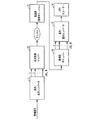
では、図1を参照して通常のデジタル無線通信システムについて説明する。 Now, a normal digital radio communication system will be described with reference to FIG.
符号化された情報ビットは、直列/並列コンバータ11を介してlog2Mビットずつ並列的に高次変調マッパー12に入力されてから、それぞれ一つのシンボルとして出力され、このシンボルは、チャネルを通過して受信端の復調器(同期モジュール)13で同期を合せてから、デマッパー14を経た後チャネル符号(反復符号であるLDPC)としてLDPC(Low Density Parity Check)デコーダー16に入力される。
The encoded information bits are input to the high-
このとき、デマッパー14では、受信したシンボルを再び分離しなければならないが、チャネル符号が反復符号の場合、軟判定値にならなければならない。
At this time, the
従来の無線通信システムでは、こうした軟判定技法として代数尤度比(LLR:Log Likelihood Ratio)方式を用いてきたが、この方式を利用する場合、複雑な演算過程によってハードウェアの大きさや電力消耗量において問題がある。これを克服するため、低複雑度軟判定技法が提案されたが、LLR方式と比較すると、BER(Bit Error Rate)性能の側面において劣化の問題があった。これを具体的に説明する。 In a conventional wireless communication system, an algebraic likelihood ratio (LLR) method has been used as such a soft decision technique. However, when this method is used, the size of hardware and the amount of power consumption are complicated by a complicated calculation process. There is a problem. In order to overcome this, a low-complexity soft decision technique has been proposed. However, compared with the LLR method, there is a problem of deterioration in terms of BER (Bit Error Rate) performance. This will be specifically described.
まず、デジタル変調方式のうち、図2を参照して8PSKの星座図を説明する。このとき、既存のLLRを利用した軟判定技法は、下記の[数式1]の通りである。
前記[数式1]において、「si」は、星座の座標であり、「r」は、受信信号を意味し、「σ2」は、付加的白色ガウス雑音(AWGN:Additive White Gaussian Noise)チャネル環境での分散を意味し、「b0,b1,b2」は、図2の8PSK星座でシンボルマップの際の各ビットであり、「LLR[b0],LLR[b1],LLR[b2]」は、b0,b1,b2の各ビットの確率値で、軟判定技法の出力である。 In [Formula 1], “s i ” is a coordinate of the constellation, “r” means a received signal, and “σ 2 ” is an additive white gaussian noise (AWGN) channel. This means dispersion in the environment, and “b0, b1, b2” are each bit in the symbol map in the 8PSK constellation of FIG. 2, and “LLR [b0], LLR [b1], LLR [b2]” are , B0, b1, and b2 are the probability values of the respective bits, and are the outputs of the soft decision technique.
前記[数式1]で確認できるように、最終出力LLRを計算するためには、数式に指数関数、ログ関数演算過程を含むことになり、この演算は、ハードウェアの演算量を大きく増加させる要因となる。これを克服するための方案として、ユークリッド距離を利用する方式(下記の[数式2]参照)と、位相の区間を利用する方式(下記の[数式3]を参照)を利用した。 As can be confirmed from [Formula 1], in order to calculate the final output LLR, the formula includes an exponential function and a log function calculation process, and this calculation is a factor that greatly increases the amount of calculation of hardware. It becomes. As a method for overcoming this, a method using the Euclidean distance (see [Formula 2] below) and a system using the phase interval (see [Formula 3] below) were used.
まず、ユークリッド距離を利用する方式を数式で表すと、下記の[数式2]の通りである。
一方、位相の区間を利用する方式は、図3と同じ星座に変形した後、下記の[数式3]の方式を利用して軟判定する。
しかしながら、上の2つの方式(ユークリッド距離を利用する方式(Euclidian)、位相の区間を利用する方式(Phase Sector))は、図8のBER(Bit Error Rate)性能曲線で分かるように、本発明のLLR方式に比べて性能の劣化の発生という問題点があった。また、前述のように、複雑な演算過程によってハードウェアの大きさ、電力消耗量において問題点があった。 However, the above two methods (method using the Euclidean distance (Euclidian) and method using the phase section (Phase Sector)) can be understood from the BER (Bit Error Rate) performance curve of FIG. Compared with the LLR method, there is a problem that performance is deteriorated. In addition, as described above, there are problems in the size of hardware and the amount of power consumption due to complicated calculation processes.
本発明は、上記の問題点を解決するためになされたものであって、その目的は、ハードウェア演算量の負担を減らし、BER性能の劣化がない軟判定ビット分散方式によって、複雑な指数演算及びログ演算を避け、簡単に実現可能な比較演算を利用し、軟判定ビットを得ることができる、シャノンの限界に近づく性能を要求するデジタル無線通信システムに適合した軟判定デマップ方法、及びそれを利用したエラー訂正装置を提供することにある。 The present invention has been made to solve the above-described problems, and its object is to reduce the burden of hardware calculation amount and to perform complex exponential calculation by a soft decision bit distribution method that does not degrade BER performance. A soft decision demapping method suitable for a digital wireless communication system that requires performance approaching the Shannon limit, which can obtain a soft decision bit by using a comparison operation that can be easily realized, avoiding log operations, and The object is to provide an error correction device that utilizes the above.
上記の目的を達成するための本発明は、2N(ここでNは正の定数)位相変調システムでの軟判定デマップ方法において、受信信号(r)と星座座標(si)との間の距離値(Pi)を定義するステップと、Nビット受信信号シンボルの最上位ビット(最初のビット)を軟判定するにあたって、最初のビットが0である距離値(Pi)の最大値と最初のビットが1である距離値の最大値の差とを求めるステップと、前記Nビット受信信号シンボルの2番目のビットを軟判定するにあたって、2番目のビットが0である距離値(Pi)の最大値と、2番目のビットが1である距離値の最大値との差を求めるステップと、前記Nビット受信信号シンボルの所定の順番のビットを軟判定するにあたって、当該所定の順番のビットが0である距離値(Pi)の最大値と、当該所定の順番のビットが1である距離値の最大値との差を求めるステップとを含むことを特徴とする。 To achieve the above object, the present invention provides a soft decision demapping method in a 2 N (where N is a positive constant) phase modulation system between a received signal (r) and constellation coordinates (s i ). In the step of defining the distance value (P i ) and the soft decision of the most significant bit (first bit) of the N-bit received signal symbol, the maximum value and the first value of the distance value (P i ) whose first bit is 0 A distance value (P i ) in which the second bit is 0 when the second bit of the N-bit received signal symbol is soft-determined. In the step of obtaining the difference between the maximum value of the distance value and the maximum value of the distance value in which the second bit is 1, and in the soft decision of the bits in the predetermined order of the N-bit received signal symbol, Distance that is 0 A step of obtaining a difference between the maximum value of the outlier (P i ) and the maximum value of the distance value in which the bit in the predetermined order is 1.
一方、本発明は、前記軟判定デマップ方法によって、受信シンボルが各ビットで軟判定される値を受信してエラーを訂正する装置において、チャネル符号が反復符号である場合、軟判定デマッパーから高次変調次数の分のビットを軟判定で分離した値を受信し、適応復調信号及び変調方式情報によりエラーを訂正してシャノンの限界(Shannon Limit)に近づいた性能を有することを特徴とする。 On the other hand, according to the present invention, in the apparatus for receiving an error correction value by receiving a value in which a received symbol is soft-decided by each bit by the soft decision demapping method, when the channel code is a repetitive code, the soft decision demapper A value obtained by separating bits of the modulation order by soft decision is received, and an error is corrected by an adaptive demodulated signal and modulation scheme information, thereby having a performance approaching the Shannon limit.
本発明は、デジタル無線通信システムの反復デコーダーの入力によってハードウェアの大きさを小さくし、電力消耗量を低減し、かつ、性能劣化のない軟判定を得ることができるので、次期衛星放送システムDVB−S2のシステムであるLDPCデコーダーと復調器との間のデマッパーとして効率的に適用できる効果がある。 Since the present invention can reduce the size of hardware, reduce power consumption, and obtain a soft decision without performance degradation by the input of an iterative decoder of a digital wireless communication system, the next satellite broadcasting system DVB -There exists an effect which can be efficiently applied as a demapper between the LDPC decoder which is the system of S2, and a demodulator.
本発明の軟判定デマップ方法(デマッパー)は、反復符号の入力によって受信信号をデマップするにあたり、様々な高次変調方式に適した低複雑度を有しながらも、受信した信号を軟判定するにあたって性能の劣化がない。 The soft decision demapping method (demapper) of the present invention has a low complexity suitable for various high-order modulation schemes and soft decision on a received signal when demapping a received signal by inputting a repetition code. There is no performance degradation.
このため、本発明の軟判定デマップ方法(デマッパー)は、デジタル無線通信システムにおいて、高次変調方式の場合、受信するシンボルの値を利用してチャネル符号(反復符号)の入力によって高次変調の指数分のビットを軟判定によって分離するが、このとき、受信した信号から軟判定値を出力するにあたり、必要な指数関数及びログ関数の演算方式を排除し、簡単な比較演算を利用して性能の劣化なしに軟判定値を得る。 For this reason, the soft decision demapping method (demapper) of the present invention, in the case of a high-order modulation system in a digital radio communication system, uses a received symbol value to input a high-order modulation by inputting a channel code (repetitive code). Exponential bits are separated by soft decision, but at this time, when outputting a soft decision value from the received signal, it eliminates the necessary exponential function and log function calculation method, and uses a simple comparison operation for performance. A soft decision value is obtained without deterioration of
本発明によれば、高次変調方式を利用した反復符号(LDPC、Turbo、TPC等)に利用できる。すなわち、高次変調方式によってマップされた受信信号を効率的に軟判定値として出力することによって、デジタル衛星放送システムの反復符号(LDPC、Turbo、TPC等)と結合し、シャノンの限界に近づいた性能に到達することができる。 According to the present invention, it can be used for repetitive codes (LDPC, Turbo, TPC, etc.) using a higher-order modulation system. That is, by efficiently outputting a received signal mapped by a high-order modulation method as a soft decision value, it is combined with a repetitive code (LDPC, Turbo, TPC, etc.) of a digital satellite broadcasting system and approaches the Shannon limit. Performance can be reached.
以下、本発明の最も好ましい実施形態を添付した図面を参照しながら説明する。 Hereinafter, a most preferred embodiment of the present invention will be described with reference to the accompanying drawings.
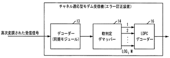
図6は、本発明に係る軟判定デマップ方法(軟判定デマッパー)を適用したチャネル適応型モデム受信器(エラー訂正装置)の実施形態を示す構成図である。 FIG. 6 is a block diagram showing an embodiment of a channel adaptive modem receiver (error correction apparatus) to which the soft decision demapping method (soft decision demapper) according to the present invention is applied.
次期デジタル衛星放送システム(DVB−S2)において、チャネル符号として用いられるLDPC符号は、代表的な反復符号のうちの1つであり、従って、SISO(Soft Input Soft Output)を基にしている。このために、LDPCデコーダー16は、入力として受信信号の軟判定値を要求し、この軟判定方式によってLDPCデコーダー16の性能が変化する。従って、LDPCデコーダー16の入力端には、受信信号を効率的に軟判定できるデマッパー(軟判定デマッパー)14が必要である。従って、LDPCデコーダー16は、軟判定デマップ14の軟判定値を受信して、適応復調信号及び変調方式情報によりエラーを訂正することができる。
In the next digital satellite broadcasting system (DVB-S2), an LDPC code used as a channel code is one of typical repetitive codes, and is therefore based on SISO (Soft Input Soft Output). For this reason, the
本発明の軟判定デマッパー(軟判定デマップ方法)14では、実現が簡単な比較演算を利用して良好な性能を見せ、かつ、別途の複雑な指数演算及びログ演算を必要としない。 The soft decision demapper (soft decision demapping method) 14 of the present invention uses a comparison operation that is easy to implement and exhibits good performance, and does not require separate complicated exponential calculation and log calculation.
前記従来技術に係るLLR方式は、前記[数式1]のように受信信号(r)と星座の座標(si)との間の数学的演算によってPiを導くにあたって指数演算を含み、これを再びログ演算を利用して最終的にLLR値を導く。 Wherein the LLR method according to the prior art, comprises an exponent operation when guiding the P i by mathematical calculation between the received signal (r) and constellation coordinates (s i) as described above [Equation 1], this Using the log operation again, the LLR value is finally derived.
しかし、本発明の軟判定デマッパー(軟判定デマップ方法)14では、下記の[数式4]の性質を利用して前記[数式1]を下記の[数式5]のように導くことができる。
前記[数式5]で、「r」は、受信シンボルであり、「si」は、それぞれの星座(星座の座標)であり、「σ2」は、AWGN(Additive White Gaussian Noise)チャネル環境での分散を意味している。 In [Formula 5], “r” is a received symbol, “s i ” is a respective constellation (constellation coordinates), and “σ 2 ” is an AWGN (Additional White Gaussian Noise) channel environment. Means dispersion.
結局、Piは、受信信号(r)と星座座標(si)との間の距離値を意味し、8PSKの場合、P0は「000」、P1は「001」、P2は「010」、P3は「011」、P4は「100」、P5は「101」、P6は「110」、P7は「111」を意味する。 After all, Pi means a distance value between the received signal (r) and the constellation coordinates (s i ). In the case of 8PSK, P 0 is “000”, P 1 is “001”, and P 2 is “010”. ”, P 3 means“ 011 ”, P 4 means“ 100 ”, P 5 means“ 101 ”, P 6 means“ 110 ”, and P 7 means“ 111 ”.
そして、「b0、b1、b2」は、図2の8PSK星座においてシンボルマップの際の各ビットであり、「LLR[b0]、LLR[b1]、LLR[b2]」は、b0、b1、b2の各ビットの確率値で、軟判定技法の出力である。 “B0, b1, b2” are bits in the symbol map in the 8PSK constellation of FIG. 2, and “LLR [b0], LLR [b1], LLR [b2]” are b0, b1, b2 Is the output of the soft decision technique.
従って、8PSKの場合、LLR[b2」は最上位ビット(最初のビット)の軟判定値、LLR[b1」は2番目のビットの軟判定値、LLR[b0」は3番目のビットの軟判定値を意味している。 Therefore, in the case of 8PSK, LLR [b2] is the soft decision value of the most significant bit (first bit), LLR [b1] is the soft decision value of the second bit, and LLR [b0] is the soft decision value of the third bit. Means value.
従って、3ビット受信信号のシンボルの最上位ビット(最初のビット)を軟判定するにあたっては(LLR[b2])、最初のビットが0の距離値(Pi)の最大値(max(P0,P1,P2,P3))と、最初のビットが1である距離値の最大値(max(P4,P5,P6,P7))との差を求めるとよい。 Therefore, when softly determining the most significant bit (first bit) of the symbol of the 3-bit received signal (LLR [b2]), the maximum value (max (P 0 , P 1 , P 2 , P 3 )) and the maximum distance value (max (P 4 , P 5 , P 6 , P 7 )) whose first bit is 1 may be obtained.
また、3ビット受信信号のシンボルの2番目のビットを軟判定するにあたっては(LLR[b1])、2番目のビットが0である距離値(Pi)の最大値(max(P0,P1,P4,P5))と2番目のビットが1である距離値の最大値(max(P2,P3,P6,P7))との差を求めればよい。 In soft decision of the second bit of the symbol of the 3-bit received signal (LLR [b1]), the maximum value (max (P 0 , P 0 ) of the distance value (P i ) in which the second bit is 0. 1 , P 4 , P 5 )) and the maximum distance value (max (P 2 , P 3 , P 6 , P 7 )) whose second bit is 1.
また、3ビット受信信号のシンボルの3番目のビットを軟判定するにあったて(LLR[b0])、3番目のビットが0の距離値(Pi)の最大値(max(P0,P2,P4,P6))と3番目のビットが1である距離値の最大値(max(P1,P3,P5,P7))の差を求めればよい。
Further, 3 had a third bit of the symbol bit received signal soft determines (LLR [b0]), 3-th
こうすることによって、[数式5]における指数演算とログ演算の過程が省略され、比較演算器のみで実現可能であり、実際のハードウェアの実現の際の複雑さを低減させることができる。従って、8PSKの場合、図7に示すように2入力/1出力を有する7つのコンパレータを介して軟判定値を出力することができる。 By doing so, the process of the exponent operation and the log operation in [Formula 5] is omitted, and it can be realized only by the comparison operation unit, and the complexity in realizing the actual hardware can be reduced. Therefore, in the case of 8PSK, the soft decision value can be output through seven comparators having two inputs / one output as shown in FIG.
図8は、本発明に8PSK変調方式を適用した場合、既存の方式(ユークリッド距離を利用する方式及び位相の区間を利用する方式)と本発明に係るLLRとのBER性能を比較したグラフである。このときに用いられた反復符号は、DVB−S2標準案に提示されたLDPCであり、このときの符号化率は2/3である。 FIG. 8 is a graph comparing the BER performance of an existing method (a method using a Euclidean distance and a method using a phase interval) and the LLR according to the present invention when the 8PSK modulation method is applied to the present invention. . The repetition code used at this time is the LDPC presented in the DVB-S2 standard proposal, and the coding rate at this time is 2/3.
同図に示すように、本発明のLLR方式は、性能の劣化がなく、位相セクターを利用した方式やユークリッド距離を利用した方式に比べて約0.3dB程度の性能が優れていることが分かる。 As shown in the figure, the LLR method of the present invention has no performance degradation, and it is understood that the performance of about 0.3 dB is superior to the method using the phase sector and the method using the Euclidean distance. .
一方、前記[数式4]の性質を利用して、図4の16APSKの星座を下記の[数式6]のように導くことができる。
前記[数式6]で、「r」は受信シンボルであり、「si」はそれぞれの星座(星座の座標)であり、「σ2」はAWGNチャネル環境での分散を意味している。 In [Formula 6], “r” is a received symbol, “s i ” is each constellation (constellation coordinates), and “σ 2 ” means dispersion in the AWGN channel environment.
結局、Piは受信信号(r)と星座座標(si)との間の距離値を意味し、8PSKの場合、P0は「0000」、P1は「0001」、P2は「0010」、P3は「0011」、P4は「0100」、P5は「0101」、P6は「0110」、P7は「0111」、P8は「1000」、P9は「1001」、P10は「1010」、P11は「1011」、P12は「1100」、P13は「1101」、P14は「1110」、P15は「1111」を意味している。 After all, P i means a distance value between the received signal (r) and the constellation coordinates (s i ). In the case of 8PSK, P 0 is “0000”, P 1 is “0001”, and P 2 is “0010”. ”, P 3 is“ 0011 ”, P 4 is“ 0100 ”, P 5 is“ 0101 ”, P 6 is“ 0110 ”, P 7 is“ 0111 ”, P 8 is“ 1000 ”, and P 9 is“ 1001 ”. , P 10 means “1010”, P 11 means “1011”, P 12 means “1100”, P 13 means “1101”, P 14 means “1110”, and P 15 means “1111”.
そして、「b0,b1,b2,b3」は、図4の16APSK星座においてシンボルマップの際の各ビットであり、「LLR[b0],LLR[b1],LLR[b2],LLR[b3]」はb0,b1,b2,b3の各ビットの確率値であり、軟判定技法の出力である。 “B0, b1, b2, b3” are each bit in the symbol map in the 16APSK constellation of FIG. 4, and “LLR [b0], LLR [b1], LLR [b2], LLR [b3]”. Is a probability value of each bit of b0, b1, b2, and b3, and is an output of the soft decision technique.
従って、16APSKの場合、LLR[b3」は最上位ビット(最初のビット)の軟判定値、LLR[b2」は2番目のビットの軟判定値、LLR[b1」は3番目のビットの軟判定値、LLR[b0」は4番目のビットの軟判定値を意味している。 Therefore, in the case of 16APSK, LLR [b3] is the soft decision value of the most significant bit (first bit), LLR [b2] is the soft decision value of the second bit, and LLR [b1] is the soft decision value of the third bit. The value LLR [b0] means the soft decision value of the fourth bit.
従って、4ビット受信信号シンボルの最上位ビット(最初のビット)を軟判定するにあたっては(LLR[b3])、最初のビットが0である距離値(Pi)の最大値(max(P0,P1,P2,P3,P4,P5,P6,P7))と最初のビットが1である距離値の最大値(max(P8,P9,P10,P11,P12,P13,P14,P15))との差を求めればよい。 Therefore, when the most significant bit (first bit) of the 4-bit received signal symbol is softly determined (LLR [b3]), the maximum value (max (P 0 ) of the distance value (P i ) where the first bit is 0. , P 1 , P 2 , P 3 , P 4 , P 5 , P 6 , P 7 )) and the maximum distance value (max (P 8 , P 9 , P 10 , P 11 ) whose first bit is 1. , P 12 , P 13 , P 14 , P 15 )).
また、4ビット受信信号シンボルの2番目のビットを軟判定するにあたっては(LLR[b2])、2番目のビットが0である距離値(Pi)の最大値(max(P0,P1,P2,P3,P8,P9,P10,P11))とm2番目のビットが1である距離値の最大値(max(P4,P5,P6,P7,P12,P13,P14,P15))との差を求めればよい。 In soft decision of the second bit of the 4-bit received signal symbol (LLR [b2]), the maximum value (max (P 0 , P 1 ) of the distance value (P i ) at which the second bit is 0. , P 2 , P 3 , P 8 , P 9 , P 10 , P 11 )) and the maximum distance value (max (P 4 , P 5 , P 6 , P 7 , P 11 ) whose m2nd bit is 1. 12 , P 13 , P 14 , P 15 )).
また、4ビット受信信号シンボルの3番目のビットを軟判定するにあたっては(LLR[b1])、3番目のビットが0である距離値(Pi)の最大値(max(P0,P1,P4,P5,P8,P9,P12,P13))と、3番目のビットが1である距離値の最大値(max(P2,P3,P6,P7,P10,P11,P14,P15))との差を求めればよい。 In soft decision of the third bit of the 4-bit received signal symbol (LLR [b1]), the maximum value (max (P 0 , P 1 ) of the distance value (P i ) where the third bit is 0. , P 4 , P 5 , P 8 , P 9 , P 12 , P 13 )) and the maximum distance value (max (P 2 , P 3 , P 6 , P 7 , P 10 , P 11 , P 14 , P 15 )) may be obtained.
また、4ビット受信信号シンボルの4番目のビットを軟判定するにあたっては(LLR[b0])、4番目のビットが0である距離値(Pi)の最大値(max(P0,P2,P4,P6,P8,P10,P12,P14))と、4番目のビットが1である距離値の最大値(max(P1,P3,P5,P7,P9,P11,P13,P15))との差を求めればよい。 In soft decision of the fourth bit of the 4-bit received signal symbol (LLR [b0]), the maximum value (max (P 0 , P 2 ) of the distance value (P i ) where the fourth bit is 0. , P 4 , P 6 , P 8 , P 10 , P 12 , P 14 )) and the maximum distance value (max (P 1 , P 3 , P 5 , P 7 , P 9 , P 11 , P 13 , P 15 )) may be obtained.
こうすることによって、[数式6]において、指数演算及びログ演算過程が省略され、比較演算器だけで実現可能であって、実際のハードウェアの実現の際の複雑性を低減させることができる。従って、16APSKの場合、2入力/1出力を有する15のコンパレータを介して軟判定値を出力することができる。 By doing so, in [Formula 6], the exponent operation and log operation steps are omitted, and it can be realized only by the comparison operation unit, and the complexity in realizing the actual hardware can be reduced. Therefore, in the case of 16APSK, the soft decision value can be output via 15 comparators having 2 inputs / 1 output.
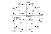
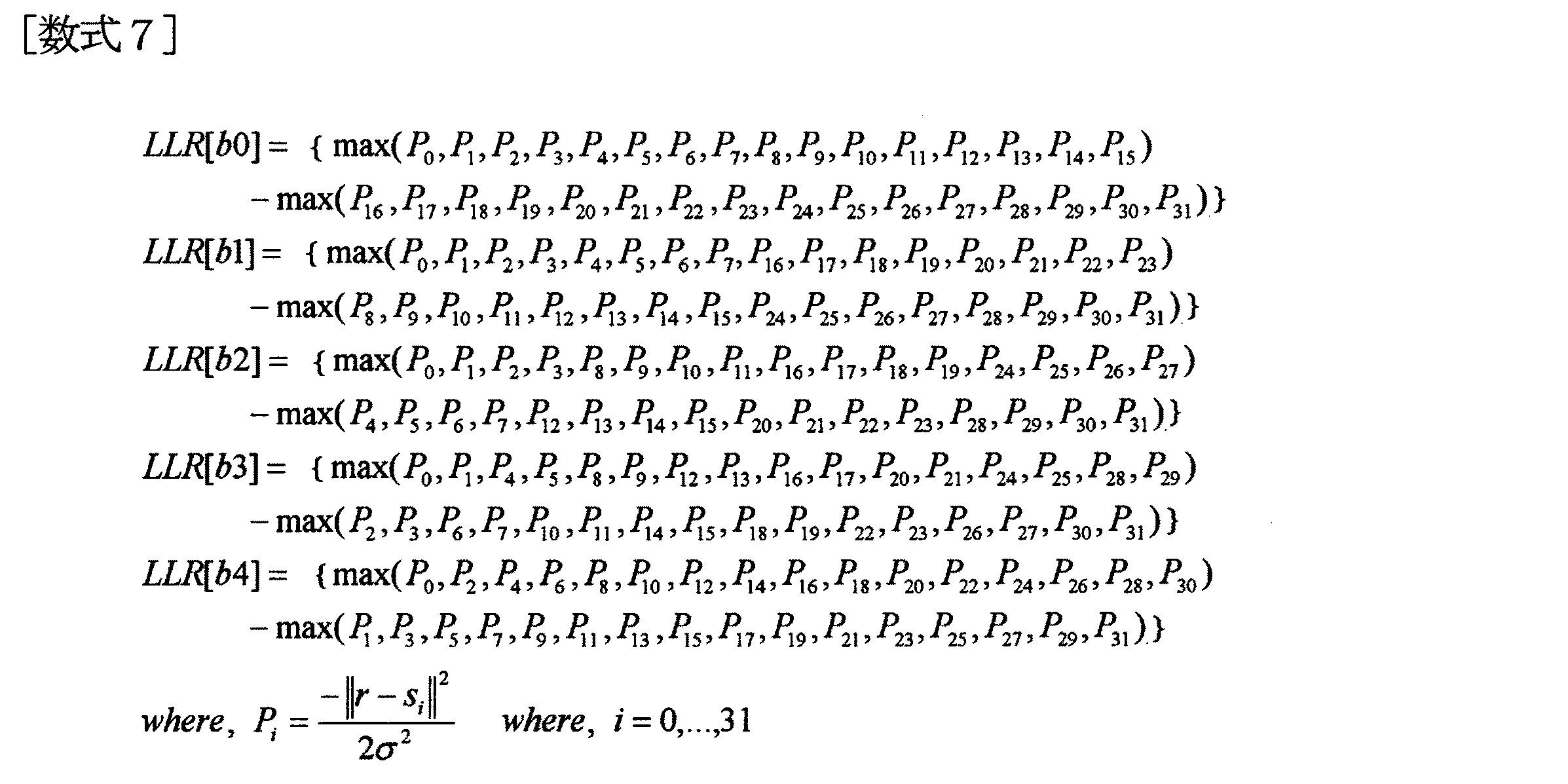
一方、前記[数式4]の性質を利用して図5の32APSKの星座を下記の[数式7]のように導くことができる。
前記[数式7]において、「r」は受信シンボルであり、「si」はそれぞれの星座(星座の座標)であり、「σ2」はAWGNチャネル環境での分散を意味している。 In [Formula 7], “r” is a received symbol, “s i ” is a constellation (coordinates of each constellation), and “σ 2 ” means dispersion in the AWGN channel environment.
結局、Piは受信信号(r)と星座座標(si)との間の距離値を意味し、8PSKの場合、P0は「00000」、P1は「00001」、P2は「00010」、P3は「00011」、P4は「00100」、P5は「00101」、P6は「00110」、P7は「00111」、P8は「01000」、P9は「01001」、P10は「01010」、P11は「01011」、P12は「01100」、P13は「01101」、P14は「01110」、P15は「01111」、P16は「10000」、P17は「10001」、P18は「10010」、P19は「10011」,…,P30は「11110」、P31は「11111」を意味している。 After all, P i means a distance value between the received signal (r) and the constellation coordinates (s i ). In the case of 8PSK, P 0 is “00000”, P 1 is “00001”, and P 2 is “00010”. ”, P 3 is“ 00011 ”, P 4 is“ 00100 ”, P 5 is“ 00101 ”, P 6 is“ 00110 ”, P 7 is“ 00111 ”, P 8 is“ 01000 ”, and P 9 is“ 01001 ”. , P 10 is “01010”, P 11 is “01011”, P 12 is “01100”, P 13 is “01101”, P 14 is “01110”, P 15 is “01111”, P 16 is “10000”, P 17 means “10001”, P 18 means “10010”, P 19 means “10011”,..., P 30 means “11110”, and P 31 means “11111”.
そして、「b0,b1,b2,b3,b4」は、図5の32APSK星座においてシンボルマップの際の各ビットであり、「LLR[b0],LLR[b1],LLR[b2],LLR[b3],LLR[b4]」はb0,b1,b2,b3,b4の各ビットの確率値であり、軟判定技法の出力である。 “B0, b1, b2, b3, b4” are each bit in the symbol map in the 32APSK constellation of FIG. 5, and “LLR [b0], LLR [b1], LLR [b2], LLR [b3” ], LLR [b4] ”is the probability value of each bit of b0, b1, b2, b3, and b4, and is the output of the soft decision technique.
従って、32APSKの場合、LLR[b0」は、最上位ビット(最初のビット)の軟判定値、LLR[b1」は、2番目のビットの軟判定値、LLR[b2」は、3番目のビットの軟判定値、LLR[b3」は、4番目のビットの軟判定値、LLR[b4」は、5番目のビットの軟判定値を意味している。 Therefore, in the case of 32APSK, LLR [b0] is the soft decision value of the most significant bit (first bit), LLR [b1] is the soft decision value of the second bit, and LLR [b2] is the third bit. , LLR [b3] means the fourth bit soft decision value, and LLR [b4] means the fifth bit soft decision value.
従って、5ビット受信信号シンボルの最上位ビット(最初のビット)を軟判定するにあたって(LLR[b0])、最初のビットが0である距離値(Pi)の最大値(max(P0,P1,P2,P3,P4,P5,P6,P7,P8,P9,P10,P11,P12,P13,P14,P15))と、最初のビットが1である距離値の最大値(max(P16,P17,P18,P19,P20,P21,P22,P23,P24,P25,P26,P27,P28,P29,P30,P31))との差を求めればよい。
Therefore, the most significant bit of the 5-bit received signal symbol (first bit) When soft determines (LLR [b0]), the distance values the first bit is 0 the maximum value of (P i) (
同じく、5ビット受信信号シンボルの2番目のビット、3番目のビット、4番目のビット、5番目のビットを軟判定(LLR[b1]、LLR[b2]、LLR[b3]、LLR[b4])することができる。 Similarly, the second bit, the third bit, the fourth bit, and the fifth bit of the 5-bit received signal symbol are softly determined (LLR [b1], LLR [b2], LLR [b3], LLR [b4]. )can do.
こうすることによって、[数式7]において、指数演算及びログ演算の過程が省略され、比較演算器のみで実現可能であり、実際のハードウェアの実現の際の複雑さを低減させることができる。従って、32APSK場合、2入力/1出力を有する31のコンパレータを介して軟判定値を出力することができる。 By doing so, in [Formula 7], the process of exponential calculation and log calculation is omitted, and it can be realized only by the comparison arithmetic unit, and the complexity at the time of actual hardware implementation can be reduced. Therefore, in the case of 32APSK, a soft decision value can be output via 31 comparators having 2 inputs / 1 output.
図9及び図10は、本発明に16APSK,32APSKの変調方式をそれぞれ適用した場合、既存の方式(ユークリッド距離を利用する方式)及び本発明に係るLLRのBER性能を比較したグラフである。このとき用いられた反復符号は、DVB−S2標準案に提示されたLDPCであり、このときの符号化率は3/4である。 9 and 10 are graphs comparing the BER performance of the LLR according to the present invention (method using the Euclidean distance) when the 16APSK and 32APSK modulation methods are applied to the present invention, respectively. The repetition code used at this time is the LDPC presented in the DVB-S2 standard proposal, and the coding rate at this time is 3/4.
図9及び図10から分かるように、本発明のLLR方式は、ユークリッド距離を利用した方式に比べて性能の劣化がなく、優れた性能を有する。 As can be seen from FIGS. 9 and 10, the LLR system of the present invention has superior performance as compared with the system using the Euclidean distance, and has superior performance.
このように16APSK、32APSKでの適用した場合も、8PSKの場合のようにLLR方式に比べて性能の劣化がなく、これは高次変調方式においても適用可能な方式であることがわかる。 Thus, even when applied to 16APSK and 32APSK, there is no performance degradation compared to the LLR method as in the case of 8PSK, and it can be seen that this is a method applicable also to a high-order modulation method.
上述したように、本発明の方法はプログラムによって実現され、コンピュータで読むことができる形態で記録媒体(CD−ROM、RAM、ROM、フロッピーディスク、ハードディスク、光磁器ディスク等)に保存が可能である。このような過程は、本発明が属する技術分野で通常の知識を有する者が容易に実施できるため、これ以上詳しく説明しないことにする。 As described above, the method of the present invention is realized by a program and can be stored in a recording medium (CD-ROM, RAM, ROM, floppy disk, hard disk, magneto-optical disk, etc.) in a form that can be read by a computer. . Such a process can be easily performed by a person having ordinary knowledge in the technical field to which the present invention belongs, and will not be described in further detail.
尚、本発明は、上記した実施形態に限定されるものではなく、本発明に係る技術的思想の範囲内から逸脱しない範囲内で様々な変更が可能であり、それらも本発明の技術的範囲に属する。 The present invention is not limited to the above-described embodiment, and various modifications are possible without departing from the scope of the technical idea according to the present invention, and these are also within the technical scope of the present invention. Belonging to.
13 復調器(同期モジュール)
14 軟判定デマッパー
16 反復符号(LDPC)デコーダー
13 Demodulator (synchronization module)
14
Claims (5)
受信信号(r)と星座座標(si)との間の距離値(Pi)を定義するステップと、
Nビット受信信号シンボルの最上位ビット(最初のビット)を軟判定するにあたって、
最初のビットが0である距離値(Pi)の最大値と最初のビットが1である距離値の最大値の差とを求めるステップと、
前記Nビット受信信号シンボルの2番目のビットを軟判定するにあたって、2番目のビットが0である距離値(Pi)の最大値と、2番目のビットが1である距離値の最大値との差を求めるステップと、
前記Nビット受信信号シンボルの所定の順番のビットを軟判定するにあたって、当該所定の順番のビットが0である距離値(Pi)の最大値と、当該所定の順番のビットが1である距離値の最大値との差を求めるステップと
を含むことを特徴とする反復デコーダーのための高次変調方式に適する軟判定デマップ方法。 In a soft decision demapping method in a 2 N (where N is a positive constant) phase modulation system,
Defining a distance value (P i ) between the received signal (r) and the constellation coordinates (s i );
In soft-deciding the most significant bit (first bit) of an N-bit received signal symbol,
Determining the difference between the maximum distance value (P i ) with the first bit being 0 and the maximum distance value with the first bit being 1;
In soft-deciding the second bit of the N-bit received signal symbol, the maximum value of the distance value (P i ) in which the second bit is 0, and the maximum value of the distance value in which the second bit is 1; Calculating the difference between
In soft-deciding a predetermined order bit of the N-bit received signal symbol, the maximum distance value (P i ) for which the predetermined order bit is 0 and the distance for which the predetermined order bit is 1 A soft decision demapping method suitable for a high-order modulation scheme for an iterative decoder, comprising: calculating a difference from a maximum value.
下記の[数式5]のように、比較演算のみで実現可能であることを特徴とする請求項1に記載の反復デコーダーのための高次変調方式に適する軟判定デマップ方法。
The soft decision demapping method suitable for a high-order modulation method for an iterative decoder according to claim 1, wherein the soft decision demapping method can be realized only by a comparison operation as shown in [Formula 5] below.
下記の[数式6]のように、比較演算のみで実現可能であることを特徴とする請求項1に記載の反復デコーダーのための高次変調方式に適する軟判定デマップ方法。
The soft decision demapping method suitable for a high-order modulation method for an iterative decoder according to claim 1, wherein the soft decision demapping method can be realized only by a comparison operation as in the following [Formula 6].
下記の[数式7]のように、比較演算のみで実現可能なことを特徴とする請求項1に記載の反復デコーダーのための高次変調方式に適する軟判定デマップ方法。
The soft decision demapping method suitable for a high-order modulation method for an iterative decoder according to claim 1, wherein the soft decision demapping method can be realized only by a comparison operation as shown in [Formula 7] below.
チャネル符号が反復符号である場合、軟判定デマッパーから高次変調次数の分のビットを軟判定で分離した値を受信し、適応復調信号及び変調方式情報によりエラーを訂正してシャノンの限界(Shannon Limit)に近づいた性能を有することを特徴とするエラー訂正装置。 In the soft decision demapping method according to any one of claims 1 to 4, an apparatus that receives a value in which a received symbol is softly determined in each bit and corrects an error,
When the channel code is an iterative code, a value obtained by separating the bits of the higher-order modulation order by soft decision is received from the soft decision demapper, and the error is corrected by the adaptive demodulated signal and the modulation scheme information. An error correction apparatus characterized by having performance close to that of Limit).
Applications Claiming Priority (1)
| Application Number | Priority Date | Filing Date | Title |
|---|---|---|---|
| KR1020050121114A KR100706618B1 (en) | 2005-12-09 | 2005-12-09 | Soft decision method on the high order modulation for the iterative decoder and error correction apparatus using it |
Publications (1)
| Publication Number | Publication Date |
|---|---|
| JP2007166592A true JP2007166592A (en) | 2007-06-28 |
Family
ID=38057378
Family Applications (1)
| Application Number | Title | Priority Date | Filing Date |
|---|---|---|---|
| JP2006290246A Pending JP2007166592A (en) | 2005-12-09 | 2006-10-25 | Soft decision demapping method suitable for high-order modulation for iterative decoder and error correction apparatus using it |
Country Status (4)
| Country | Link |
|---|---|
| US (1) | US7761777B2 (en) |
| EP (1) | EP1806894A3 (en) |
| JP (1) | JP2007166592A (en) |
| KR (1) | KR100706618B1 (en) |
Cited By (1)
| Publication number | Priority date | Publication date | Assignee | Title |
|---|---|---|---|---|
| JP2010527552A (en) * | 2007-05-17 | 2010-08-12 | サムスン エレクトロニクス カンパニー リミテッド | Soft decision value generating apparatus and method |
Families Citing this family (6)
| Publication number | Priority date | Publication date | Assignee | Title |
|---|---|---|---|---|
| JP4697126B2 (en) * | 2006-11-21 | 2011-06-08 | 株式会社デンソー | Soft decision correction method, receiver, program |
| US20110004810A1 (en) * | 2009-07-06 | 2011-01-06 | Himax Media Solutions, Inc. | Method and System of Receiving Data with Enhanced Error Correction |
| US20110150143A1 (en) * | 2009-12-18 | 2011-06-23 | Electronics And Telecommunications Research Institute | Soft-decision demapping method for digital signal |
| KR20110071225A (en) * | 2009-12-21 | 2011-06-29 | 한국전자통신연구원 | Bits-to-symbol mapping method for 4+12+16 modulation |
| JP5992916B2 (en) * | 2012-03-13 | 2016-09-14 | パナソニック株式会社 | Wireless communication device |
| US9031168B1 (en) * | 2014-04-21 | 2015-05-12 | Northrop Grumman Systems Corporation | Constellation design and optimization in non-linear satellite channels |
Citations (7)
| Publication number | Priority date | Publication date | Assignee | Title |
|---|---|---|---|---|
| JP2002198829A (en) * | 2000-12-26 | 2002-07-12 | Sony Corp | Decoder and decoding method |
| JP2003526987A (en) * | 2000-03-08 | 2003-09-09 | クゥアルコム・インコーポレイテッド | Apparatus and method for calculating soft input metric for turbo decoder |
| JP2004032125A (en) * | 2002-06-24 | 2004-01-29 | Hitachi Ltd | Communication system and signal processing method |
| JP2004096747A (en) * | 2002-08-30 | 2004-03-25 | Lucent Technol Inc | Logmap processor with higher order radix |
| JP2004227761A (en) * | 2003-01-27 | 2004-08-12 | Samsung Electronics Co Ltd | Method and device for soft demodulating |
| WO2005086402A1 (en) * | 2004-03-05 | 2005-09-15 | Ntt Docomo, Inc. | Receiver apparatus, receiving method, and wireless communication system |
| JP2006174437A (en) * | 2004-12-10 | 2006-06-29 | Korea Electronics Telecommun | Receiver and signal processing method thereof |
Family Cites Families (8)
| Publication number | Priority date | Publication date | Assignee | Title |
|---|---|---|---|---|
| KR0153966B1 (en) | 1994-11-28 | 1998-11-16 | 배순훈 | Soft decision metric producing method and apparatus in ditebi decoder |
| US5740203A (en) * | 1995-09-14 | 1998-04-14 | Thomson Consumer Electronics, Inc. | Trellis demapper of a convolutional decoder for decoding pragmatic trellis codes suitable for use in a multi-channel receiver of satellite, terrestrial and cable transmitted FEC compressed-digital television data |
| JPH11215200A (en) | 1998-01-28 | 1999-08-06 | Kenwood Corp | 8 psk demapper |
| DE19912825C1 (en) * | 1999-03-22 | 2000-08-10 | Siemens Ag | Method of detecting data symbols for mobile radio systems, e.g. GSM systems |
| US6993098B2 (en) | 2001-07-12 | 2006-01-31 | Koninklijke Philips Electronics N.V. | Method and apparatus for efficient calculating distance metric |
| AU2003215593A1 (en) * | 2002-03-07 | 2003-09-16 | Telefonaktiebolaget Lm Ericsson (Publ) | Soft value calculation for multilevel signals |
| JP2003324356A (en) | 2002-05-01 | 2003-11-14 | Sony Corp | Device and method for encoding, and device and method for decoding |
| US7308047B2 (en) * | 2003-12-31 | 2007-12-11 | Intel Corporation | Symbol de-mapping methods in multiple-input multiple-output systems |
-
2005
- 2005-12-09 KR KR1020050121114A patent/KR100706618B1/en not_active IP Right Cessation
-
2006
- 2006-09-11 US US11/518,247 patent/US7761777B2/en not_active Expired - Fee Related
- 2006-09-22 EP EP06254903A patent/EP1806894A3/en not_active Withdrawn
- 2006-10-25 JP JP2006290246A patent/JP2007166592A/en active Pending
Patent Citations (7)
| Publication number | Priority date | Publication date | Assignee | Title |
|---|---|---|---|---|
| JP2003526987A (en) * | 2000-03-08 | 2003-09-09 | クゥアルコム・インコーポレイテッド | Apparatus and method for calculating soft input metric for turbo decoder |
| JP2002198829A (en) * | 2000-12-26 | 2002-07-12 | Sony Corp | Decoder and decoding method |
| JP2004032125A (en) * | 2002-06-24 | 2004-01-29 | Hitachi Ltd | Communication system and signal processing method |
| JP2004096747A (en) * | 2002-08-30 | 2004-03-25 | Lucent Technol Inc | Logmap processor with higher order radix |
| JP2004227761A (en) * | 2003-01-27 | 2004-08-12 | Samsung Electronics Co Ltd | Method and device for soft demodulating |
| WO2005086402A1 (en) * | 2004-03-05 | 2005-09-15 | Ntt Docomo, Inc. | Receiver apparatus, receiving method, and wireless communication system |
| JP2006174437A (en) * | 2004-12-10 | 2006-06-29 | Korea Electronics Telecommun | Receiver and signal processing method thereof |
Cited By (1)
| Publication number | Priority date | Publication date | Assignee | Title |
|---|---|---|---|---|
| JP2010527552A (en) * | 2007-05-17 | 2010-08-12 | サムスン エレクトロニクス カンパニー リミテッド | Soft decision value generating apparatus and method |
Also Published As
| Publication number | Publication date |
|---|---|
| KR100706618B1 (en) | 2007-04-12 |
| EP1806894A3 (en) | 2012-04-11 |
| US7761777B2 (en) | 2010-07-20 |
| EP1806894A2 (en) | 2007-07-11 |
| US20070133718A1 (en) | 2007-06-14 |
Similar Documents
| Publication | Publication Date | Title |
|---|---|---|
| JP4563455B2 (en) | Method and apparatus for calculating log approximation rate for decoding in receiver of mobile communication system | |
| EP1946509B1 (en) | Method and apparatus for normalizing input metric to a channel decoder in a wireless communication system | |
| JP5955481B2 (en) | Soft decision value generation apparatus and soft decision value generation method | |
| JP4642753B2 (en) | Apparatus and method used for interactive decoding | |
| EP1540909A2 (en) | Improving hierarchical 8psk performance | |
| CN111277536B (en) | Soft de-mapping method of DVB-S2X system and digital signal processing system | |
| JP2007166592A (en) | Soft decision demapping method suitable for high-order modulation for iterative decoder and error correction apparatus using it | |
| EP2140642B1 (en) | Method and apparatus for mitigating interference in multicarrier modulation systems | |
| US20050129147A1 (en) | Method and system for modulating and detecting high datarate symbol communications | |
| AU2013362820B2 (en) | Digital communication system | |
| JP4763057B2 (en) | Method and apparatus for normalizing metrics input to channel decoder in wireless communication system | |
| JP5287711B2 (en) | Demodulation method | |
| US20050220203A1 (en) | System & method for spreading on fading channels | |
| EP1195909A1 (en) | Method and apparatus for demodulation | |
| US8422600B2 (en) | Apparatus and method for estimating phase error based on variable step size | |
| Herzet et al. | Code-aided maximum-likelihood ambiguity resolution through free-energy minimization | |
| US8098773B1 (en) | Communication method and apparatus | |
| US7388522B2 (en) | Sequentially decoded low density parity coding (LDPC) forward error correction (FEC) in orthogonal frequency division modulation (OFDM) systems | |
| WO2011010180A1 (en) | Method and apparatus for non-binary low density party check coding | |
| KR20130037429A (en) | High order modulation demapping communication method for adaptive modulation scheme in marine communication | |
| US8640014B2 (en) | Soft bit metric generation | |
| JP5444038B2 (en) | Receiver | |
| EP2139139A1 (en) | Method and apparatus for non binary low density parity check coding | |
| KR101602598B1 (en) | Soft demapping method and apparatus for APSK modulation systems | |
| WO2023113992A1 (en) | Improved signaling techniques in the presence of phase noise and frequency offset |
Legal Events
| Date | Code | Title | Description |
|---|---|---|---|
| A621 | Written request for application examination |
Free format text: JAPANESE INTERMEDIATE CODE: A621 Effective date: 20090728 |
|
| A977 | Report on retrieval |
Free format text: JAPANESE INTERMEDIATE CODE: A971007 Effective date: 20120220 |
|
| A131 | Notification of reasons for refusal |
Free format text: JAPANESE INTERMEDIATE CODE: A131 Effective date: 20120309 |
|
| A601 | Written request for extension of time |
Free format text: JAPANESE INTERMEDIATE CODE: A601 Effective date: 20120611 |
|
| A602 | Written permission of extension of time |
Free format text: JAPANESE INTERMEDIATE CODE: A602 Effective date: 20120614 |
|
| A601 | Written request for extension of time |
Free format text: JAPANESE INTERMEDIATE CODE: A601 Effective date: 20120709 |
|
| A602 | Written permission of extension of time |
Free format text: JAPANESE INTERMEDIATE CODE: A602 Effective date: 20120712 |
|
| A601 | Written request for extension of time |
Free format text: JAPANESE INTERMEDIATE CODE: A601 Effective date: 20120809 |
|
| A602 | Written permission of extension of time |
Free format text: JAPANESE INTERMEDIATE CODE: A602 Effective date: 20120814 |
|
| A521 | Written amendment |
Free format text: JAPANESE INTERMEDIATE CODE: A523 Effective date: 20120910 |
|
| A131 | Notification of reasons for refusal |
Free format text: JAPANESE INTERMEDIATE CODE: A131 Effective date: 20121005 |
|
| A601 | Written request for extension of time |
Free format text: JAPANESE INTERMEDIATE CODE: A601 Effective date: 20130107 |
|
| A602 | Written permission of extension of time |
Free format text: JAPANESE INTERMEDIATE CODE: A602 Effective date: 20130110 |
|
| A601 | Written request for extension of time |
Free format text: JAPANESE INTERMEDIATE CODE: A601 Effective date: 20130205 |
|
| A602 | Written permission of extension of time |
Free format text: JAPANESE INTERMEDIATE CODE: A602 Effective date: 20130208 |
|
| A601 | Written request for extension of time |
Free format text: JAPANESE INTERMEDIATE CODE: A601 Effective date: 20130305 |
|
| A602 | Written permission of extension of time |
Free format text: JAPANESE INTERMEDIATE CODE: A602 Effective date: 20130308 |
|
| A02 | Decision of refusal |
Free format text: JAPANESE INTERMEDIATE CODE: A02 Effective date: 20130604 |