JP2007163777A - Image forming apparatus and image forming method - Google Patents
Image forming apparatus and image forming method Download PDFInfo
- Publication number
- JP2007163777A JP2007163777A JP2005359269A JP2005359269A JP2007163777A JP 2007163777 A JP2007163777 A JP 2007163777A JP 2005359269 A JP2005359269 A JP 2005359269A JP 2005359269 A JP2005359269 A JP 2005359269A JP 2007163777 A JP2007163777 A JP 2007163777A
- Authority
- JP
- Japan
- Prior art keywords
- image
- carrier
- toner
- roller
- image forming
- Prior art date
- Legal status (The legal status is an assumption and is not a legal conclusion. Google has not performed a legal analysis and makes no representation as to the accuracy of the status listed.)
- Pending
Links
Images


Classifications
-
- G—PHYSICS
- G03—PHOTOGRAPHY; CINEMATOGRAPHY; ANALOGOUS TECHNIQUES USING WAVES OTHER THAN OPTICAL WAVES; ELECTROGRAPHY; HOLOGRAPHY
- G03G—ELECTROGRAPHY; ELECTROPHOTOGRAPHY; MAGNETOGRAPHY
- G03G15/00—Apparatus for electrographic processes using a charge pattern
- G03G15/06—Apparatus for electrographic processes using a charge pattern for developing
- G03G15/10—Apparatus for electrographic processes using a charge pattern for developing using a liquid developer
- G03G15/11—Removing excess liquid developer, e.g. by heat
-
- G—PHYSICS
- G03—PHOTOGRAPHY; CINEMATOGRAPHY; ANALOGOUS TECHNIQUES USING WAVES OTHER THAN OPTICAL WAVES; ELECTROGRAPHY; HOLOGRAPHY
- G03G—ELECTROGRAPHY; ELECTROPHOTOGRAPHY; MAGNETOGRAPHY
- G03G2215/00—Apparatus for electrophotographic processes
- G03G2215/20—Details of the fixing device or porcess
- G03G2215/2093—Release agent handling devices
Abstract
Description
本発明は、画像形成装置および画像形成方法に関し、さらに詳しくは、揮発しない高粘度のシリコーンオイルをキャリア液とする液体トナーにより形成されたトナー画像を画像形成媒体に転写、定着させる画像形成装置および画像形成方法に関するものである。 The present invention relates to an image forming apparatus and an image forming method. More specifically, the present invention relates to an image forming apparatus for transferring and fixing a toner image formed with a liquid toner having a non-volatile high-viscosity silicone oil as a carrier liquid onto an image forming medium, and The present invention relates to an image forming method.
従来の画像形成装置では、画像形成媒体、例えば紙媒体に転写手段により転写されたトナー画像を定着するために、この紙媒体を加熱する定着手段を備える。具体的には、この定着手段は、加熱された1対の定着ローラにより構成されている。この一対の定着ローラは、所定の圧力で互いに接触しており、この一対の定着ローラ間に形成されるニップ部内にトナー画像が転写された紙媒体を通過させる。このニップ部を通過する紙媒体のトナー画像には、溶融のための熱が伝熱され、溶融したトナー画像を紙媒体に密着・浸透させるための加圧が同時に行われる。これにより、トナー画像は、必要な定着強度(紙媒体との密着強度、樹脂強度など)を発生し、固化することで、紙媒体上に、平滑な透明な色材層が形成され、画像が形成される。 A conventional image forming apparatus includes a fixing unit that heats a paper medium in order to fix the toner image transferred to the image forming medium, for example, a paper medium, by a transfer unit. Specifically, the fixing unit is composed of a pair of heated fixing rollers. The pair of fixing rollers are in contact with each other with a predetermined pressure, and the paper medium on which the toner image is transferred is passed through a nip portion formed between the pair of fixing rollers. Heat for melting is transferred to the toner image on the paper medium passing through the nip portion, and pressurization is performed simultaneously so that the melted toner image adheres to and penetrates the paper medium. As a result, the toner image generates the necessary fixing strength (adhesion strength with the paper medium, resin strength, etc.) and solidifies, so that a smooth transparent color material layer is formed on the paper medium. It is formed.
この一対の定着ローラを用いた定着手段では、紙媒体が通過する短時間、例えば数十ミリ秒程度に、この紙媒体に転写されたトナー画像を溶融させる必要がある。従って、定着手段は、紙媒体を短時間でこのトナー画像を溶融するのに最適な温度、すなわち適正溶融温度に加熱する必要がある。つまり、一対の定着ローラは、この適正溶融温度以上の温度に加熱されている必要がある。ところが、適正溶融温度は、紙媒体の品質、すなわち紙質、厚さ、含水率などによって変化することとなる。従って、例えば紙媒体の厚さが薄い場合には、溶融したトナー画像が定着ローラに付着するオフセット現象が発生する虞がある。また、例えば紙媒体の厚さが厚い場合や、含水率が高い場合には、紙媒体のトナー画像の溶融が不十分で、定着不良や、発色性の低い画像が形成されることとなる。 In the fixing means using the pair of fixing rollers, it is necessary to melt the toner image transferred to the paper medium in a short time during which the paper medium passes, for example, about several tens of milliseconds. Accordingly, the fixing unit needs to heat the paper medium to an optimum temperature for melting the toner image in a short time, that is, to an appropriate melting temperature. That is, the pair of fixing rollers needs to be heated to a temperature equal to or higher than the proper melting temperature. However, the proper melting temperature varies depending on the quality of the paper medium, that is, the paper quality, thickness, moisture content, and the like. Therefore, for example, when the paper medium is thin, there is a possibility that an offset phenomenon occurs in which the molten toner image adheres to the fixing roller. Further, for example, when the paper medium is thick or has a high water content, the toner image on the paper medium is not sufficiently melted, and an image with poor fixing or low color developability is formed.
そこで、従来の画像形成装置では、例えば特許文献1に示すように、特に高温オフセットを防ぐために、紙媒体のトナー画像と対向する定着ローラに、離型剤を塗布するものがある。この特許文献1に示す画像形成装置は、液体トナー(現像液)を用いるものであり、液体トナーに使用されているキャリア液(担体液)と定着ローラに塗布する離型剤とを、シリコーンオイルにするものである。この特許文献1に示す画像形成装置では、このシリコーンオイルを定着ローラに塗布することで、この定着ローラにトナー画像が付着することを抑制するものである。
In view of this, some conventional image forming apparatuses apply a release agent to a fixing roller facing a toner image on a paper medium in order to prevent a high temperature offset, for example, as disclosed in
しかしながら、この特許文献1に示す画像形成装置では、定着ローラにシリコーンオイルを塗布する機構が必要となる。また、定着ローラに塗布されたシリコーンオイルは、紙媒体の転写されたトナー画像上に付着する。従って、この付着したシリコーンオイルにより、画像形成媒体上に不自然な光沢感の画像が形成されることとなり、画像の質が低下するという問題もある。さらに、定着ローラに塗布されたシリコーンオイルは、紙媒体の転写されたトナー画像以外の部分に付着する。従って、紙媒体を残オイル感が残るという問題もある。
However, the image forming apparatus disclosed in
この発明は、上記に鑑みてなされたものであって、定着手段に離型剤を塗布することなく、オフセット現象を抑制することができる画像形成装置を提供することを目的とする。 The present invention has been made in view of the above, and an object of the present invention is to provide an image forming apparatus capable of suppressing an offset phenomenon without applying a release agent to a fixing unit.
上述した課題を解決し、目的を達成するために、この発明では、画像形成装置であって、揮発しない高粘度のシリコーンオイルをキャリア液とする液体トナーにより形成されたトナー画像を画像形成媒体に転写する転写手段と、前記転写手段によりトナー画像を転写する前にトナー画像に含まれるキャリア液を除去し、かつ当該転写手段によりトナー画像を転写する前に当該トナー画像に含まれるキャリア液を除去するキャリア除去量を制御するキャリア除去手段と、前記画像形成媒体に転写された前記キャリア液が含まれるトナー画像を当該画像形成媒体に定着させる定着手段と、を備えることを特徴とする。 In order to solve the above-described problems and achieve the object, according to the present invention, an image forming apparatus uses a toner image formed by a liquid toner using a high-viscosity silicone oil that does not volatilize as a carrier liquid. A transfer means for transferring, and the carrier liquid contained in the toner image is removed before the toner image is transferred by the transfer means, and the carrier liquid contained in the toner image is removed before the toner image is transferred by the transfer means. A carrier removing unit that controls the amount of carrier removed, and a fixing unit that fixes the toner image containing the carrier liquid transferred to the image forming medium to the image forming medium.
また、この発明では、画像形成方法であって、揮発しない高粘度のシリコーンオイルをキャリア液とする液体トナーにより形成されたトナー画像に含まれる当該キャリア液を当該キャリア液のキャリア除去量を制御しつつ除去するキャリア除去手順と、前記キャリア除去手段によりキャリア液が除去されたトナー画像を画像形成媒体に転写する転写手順と、前記画像形成媒体に転写された前記キャリア液が含まれるトナー画像を当該画像形成媒体に定着させる熱定着手順と、を含むことを特徴とする。 Further, according to the present invention, there is provided an image forming method for controlling the carrier removal amount of the carrier liquid contained in a toner image formed from a liquid toner having a high-viscosity silicone oil that does not volatilize as a carrier liquid. A carrier removing procedure for removing the carrier liquid, a transfer procedure for transferring the toner image from which the carrier liquid has been removed by the carrier removing means to an image forming medium, and a toner image containing the carrier liquid transferred to the image forming medium. And a heat fixing procedure for fixing to an image forming medium.
これらの発明によれば、キャリア除去手段は、転写手段によりトナー画像を転写する前にトナー画像に含まれるキャリア液のキャリア除去量をトナー画像のトナー固形分率で60%〜95%程度の範囲内に制御することができる。つまり、キャリア除去手段は、画像形成媒体に転写されたトナー画像に、揮発しない高粘度のシリコーンオイルであり定着手段に塗布される離型剤と同様の機能、すなわち定着手段にトナー画像が付着しようとする付着力を低減することができるキャリア液を残すことができる。従って、定着手段に離型剤を塗布することがなく、オフセット現象を抑制することができる。 According to these inventions, the carrier removing means has a carrier removal amount of the carrier liquid contained in the toner image before transferring the toner image by the transferring means in a range of about 60% to 95% in terms of toner solid content of the toner image. Can be controlled within. That is, the carrier removing unit functions as a release agent applied to the fixing unit, which is a high-viscosity silicone oil that does not volatilize, on the toner image transferred to the image forming medium, that is, the toner image will adhere to the fixing unit. It is possible to leave the carrier liquid that can reduce the adhesion force. Accordingly, the offset phenomenon can be suppressed without applying a release agent to the fixing unit.
また、画像形成媒体に転写されたトナー画像に含まれるキャリア液を離型剤として用いるので、形成媒体に転写されたトナー画像上に離型剤が付着する場合と比較して、画像形成媒体上に不自然な光沢感の画像が形成されることが抑制でき、画像の質の低下を抑制することができる。 In addition, since the carrier liquid contained in the toner image transferred to the image forming medium is used as a release agent, compared with the case where the release agent adheres to the toner image transferred to the forming medium, Therefore, it is possible to suppress the formation of an unnatural glossy image and to suppress the deterioration of the image quality.
さらに、離型剤として機能するキャリア液は、紙媒体に転写されたトナー画像に含まれることとなる。従って、紙媒体のトナー画像以外の部分には、キャリア液は付着しないので、紙媒体に残オイル感が残ることを抑制することができる。 Further, the carrier liquid that functions as a release agent is included in the toner image transferred to the paper medium. Accordingly, since the carrier liquid does not adhere to the portion other than the toner image of the paper medium, it is possible to suppress the residual oil feeling from remaining on the paper medium.
また、この発明では、上記画像形成装置において、前記転写手段は、少なくとも前記トナー画像を前記画像形成媒体に転写されるまで支持する画像支持ローラを備え、前記キャリア除去手段は、前記画像支持ローラと接触し、前記トナー画像に含まれるキャリア液を除去するキャリア除去ローラを前記キャリア除去量に応じた個数備えることを特徴とする。 According to the present invention, in the image forming apparatus, the transfer unit includes an image support roller that supports at least the toner image until the toner image is transferred to the image forming medium, and the carrier removal unit includes the image support roller. A number of carrier removal rollers that come into contact with each other and remove carrier liquid contained in the toner image according to the carrier removal amount are provided.
この発明によれば、キャリア除去量、すなわち画像形成媒体に転写されたトナー画像に残されるキャリア液の残存量を、画像支持ローラに接触する個数の増加に伴って、画像形成媒体に転写されたトナー画像に残されるキャリア液の残存量を減少させることができるキャリア除去ローラの個数で制御することができる。従って、キャリア除去ローラの個数の増減という、簡単な構成で、キャリア液の残存量を制御することができる。 According to the present invention, the carrier removal amount, that is, the remaining amount of the carrier liquid remaining on the toner image transferred to the image forming medium, is transferred to the image forming medium as the number of contact with the image supporting roller increases. The amount of carrier liquid remaining in the toner image can be controlled by the number of carrier removal rollers that can reduce the amount of carrier liquid remaining. Therefore, the remaining amount of the carrier liquid can be controlled with a simple configuration in which the number of carrier removal rollers is increased or decreased.
また、この発明では、上記画像形成装置において、前記転写手段は、少なくとも前記トナー画像を前記画像形成媒体に転写されるまで支持する画像支持ローラを備え、前記キャリア除去手段は、前記画像支持ローラと接触し、前記トナー画像に含まれるキャリア液を除去する1以上のキャリア除去ローラと、前記キャリア除去ローラによる前記キャリア除去量を制御するキャリア除去量制御手段とを備えることを特徴とする。 According to the present invention, in the image forming apparatus, the transfer unit includes an image support roller that supports at least the toner image until the toner image is transferred to the image forming medium, and the carrier removal unit includes the image support roller. One or more carrier removal rollers that contact and remove the carrier liquid contained in the toner image, and carrier removal amount control means for controlling the carrier removal amount by the carrier removal roller are provided.
また、この発明では、上記画像形成装置において、前記キャリア除去量制御手段は、前記キャリア除去ローラの回転方向、前記画像支持ローラとの周速度比、前記画像支持ローラとの電位差、当該画像支持ローラに対するニップ圧、あるいは前記画像支持ローラに支持された前記トナー画像の温度の少なくともいずれか1つを制御することを特徴とする。 According to the invention, in the image forming apparatus, the carrier removal amount control means includes a rotation direction of the carrier removal roller, a peripheral speed ratio with the image support roller, a potential difference with the image support roller, and the image support roller. And / or controlling the temperature of the toner image supported by the image support roller.
ここで、キャリア除去ローラは、その回転方向が画像支持ローラの回転方向と反対方向であると、同一方向回転する場合と比較して、キャリア液の残存量を著しく減少させることができる。また、キャリア除去ローラは、画像支持ローラとの周速度比の増加に伴って、キャリア液の残存量を減少させることができる。また、キャリア除去ローラは、画像支持ローラとの電位差の増加に伴って、キャリア液の残存量を減少させることができる。また、キャリア除去ローラは、画像支持ローラに対するニップ圧の増加に伴って、キャリア液の残存量を減少させることができる。また、キャリア除去ローラは、画像支持ローラに支持されたトナー画像の温度の増加、すなわちこのトナー画像の粘度の低下に伴って、キャリア液の残存量を減少させることができる。この発明によれば、キャリア除去量制御手段は、キャリア除去量、すなわち画像形成媒体に転写されたトナー画像に残されるキャリア液の残存量の制御を、例えばキャリア除去ローラの回転方向、画像支持ローラとの周速度比、画像支持ローラとの電位差、画像支持ローラに対するニップ圧、あるいはトナー画像の温度の少なくともいずれか1つを制御することで行う。従って、キャリア除去量制御手段は、トナー画像が転写手段により転写された画像形成媒体の状態に応じてキャリア液の残存量を任意に制御することができる。 Here, if the rotation direction of the carrier removal roller is opposite to the rotation direction of the image support roller, the remaining amount of the carrier liquid can be remarkably reduced as compared with the case of rotating in the same direction. In addition, the carrier removal roller can reduce the remaining amount of the carrier liquid as the peripheral speed ratio with the image support roller increases. Further, the carrier removal roller can reduce the remaining amount of the carrier liquid as the potential difference from the image support roller increases. Further, the carrier removal roller can reduce the remaining amount of the carrier liquid as the nip pressure with respect to the image support roller increases. Further, the carrier removal roller can reduce the remaining amount of the carrier liquid as the temperature of the toner image supported by the image supporting roller increases, that is, as the viscosity of the toner image decreases. According to the present invention, the carrier removal amount control means controls the carrier removal amount, that is, the remaining amount of the carrier liquid remaining in the toner image transferred to the image forming medium, for example, the rotation direction of the carrier removal roller, the image support roller Is controlled by controlling at least one of a peripheral speed ratio, a potential difference with the image support roller, a nip pressure with respect to the image support roller, and a toner image temperature. Therefore, the carrier removal amount control unit can arbitrarily control the remaining amount of the carrier liquid according to the state of the image forming medium on which the toner image is transferred by the transfer unit.
また、この発明では、上記画像形成装置において、前記キャリア除去量制御手段は、前記画像形成媒体の品質、あるいは厚みに応じて、前記キャリア除去量を算出することを特徴とする。 In the image forming apparatus, the carrier removal amount control unit may calculate the carrier removal amount according to the quality or thickness of the image forming medium.
ここで、定着手段によるトナー画像の定着時における画像形成媒体のトナー画像に含まれるキャリア液の残存量は、画像形成媒体のキャリア液の吸収量により変化する。この発明によれば、キャリア除去量制御手段は、キャリア除去量、すなわち画像形成媒体に転写されたトナー画像に残されるキャリア液の残存量を画像形成媒体のキャリア液の吸収量に影響を与える画像形成媒体の品質、あるいは厚みに応じて算出する。従って、キャリア除去量制御手段は、画像形成媒体に応じてキャリア液の残存量を任意に制御することができ、画像の質の低下をさらに抑制することができる。 Here, the remaining amount of the carrier liquid contained in the toner image of the image forming medium when the toner image is fixed by the fixing unit varies depending on the absorption amount of the carrier liquid of the image forming medium. According to this invention, the carrier removal amount control means determines the carrier removal amount, that is, the residual amount of the carrier liquid remaining in the toner image transferred to the image forming medium, which affects the absorption amount of the carrier liquid of the image forming medium. It is calculated according to the quality or thickness of the forming medium. Therefore, the carrier removal amount control means can arbitrarily control the remaining amount of the carrier liquid according to the image forming medium, and can further suppress the deterioration of the image quality.
また、この発明では、上記画像形成装置において、前記液体トナーは、レジンからなるトナー粒子と、変性シリコーンオイルからなるトナー粒子分散剤を含む前記キャリア液とにより構成されることを特徴とする。 According to the present invention, in the image forming apparatus, the liquid toner is composed of toner particles made of a resin and the carrier liquid containing a toner particle dispersant made of a modified silicone oil.
この発明によれば、変性シリコーンオイルがトナー粒子に付着する。つまり、キャリア除去ローラにより、画像形成媒体に転写される前のトナー画像に含まれるキャリア液をすべて除去しようとしても、この変性シリコーンオイルがキャリア液として微量残ることとなる。従って、この変性シリコーンオイルにより、定着手段に塗布される離型剤と同様の機能、すなわち定着手段にトナー画像が付着しようとする付着力を低減することができる。従って、定着手段に離型剤を塗布することがなく、オフセット現象を抑制することができる。 According to this invention, the modified silicone oil adheres to the toner particles. That is, even if the carrier removal roller tries to remove all the carrier liquid contained in the toner image before being transferred to the image forming medium, a small amount of the modified silicone oil remains as the carrier liquid. Therefore, the modified silicone oil can reduce the function similar to that of the release agent applied to the fixing unit, that is, the adhesion force that the toner image tends to adhere to the fixing unit. Accordingly, the offset phenomenon can be suppressed without applying a release agent to the fixing unit.
この発明にかかる画像形成装置は、定着手段に塗布される離型剤と同様の機能、すなわち定着手段にトナー画像が付着しようとする付着力を低減することができるキャリア液を残すことができるので、定着手段に離型剤を塗布することなく、オフセット現象を抑制することができる画像形成装置を提供することができる。 The image forming apparatus according to the present invention can leave the carrier liquid that can reduce the adhesion function of the toner image to adhere to the fixing unit, that is, the same function as the release agent applied to the fixing unit. Thus, it is possible to provide an image forming apparatus capable of suppressing the offset phenomenon without applying a release agent to the fixing unit.
以下、この発明につき図面を参照しつつ詳細に説明する。なお、この実施例によりこの発明が限定されるものではない。また、下記実施例における構成要素には、当業者が容易に想定できるもの或いは実質的に同一のものが含まれる。また、以下の実施例では、画像形成装置により画像を形成する画像形成媒体として紙媒体を用いる場合について説明する。ここで、画像形成装置とは、プリンタ、複写機、印刷機などの画像形成媒体に画像を形成することができるものであればいずれであっても良い。 Hereinafter, the present invention will be described in detail with reference to the drawings. Note that the present invention is not limited to the embodiments. In addition, constituent elements in the following embodiments include those that can be easily assumed by those skilled in the art or those that are substantially the same. In the following embodiments, a case where a paper medium is used as an image forming medium on which an image is formed by the image forming apparatus will be described. Here, the image forming apparatus may be any apparatus that can form an image on an image forming medium such as a printer, a copier, or a printing machine.
図1は、画像形成装置の概略構成例を示す図である。図2は、感光ユニットの構成例を示す図である。画像形成装置1は、図1に示すように、少なくとも、1以上の感光ユニット、この実施例では4つの感光ユニット2a,2b,2c,2dと、転写手段である画像支持ローラ3およびバックアップローラ4と、キャリア除去手段である複数のキャリア除去ローラ5a,5b,5c,5d,5eと、定着手段である一対の定着ローラ6a,6bと、一対の給紙ローラ7a,7bと、キャリア除去量制御手段として機能する制御装置8とにより構成されている。この画像形成装置1は、液体トナーを用いた電子写真方式の画像形成装置である。なお、9は、画像支持ローラ3上に紙媒体に転写されずに残ったトナー画像を除去し、この画像支持ローラ3を清浄に保つクリーン装置である。
FIG. 1 is a diagram illustrating a schematic configuration example of an image forming apparatus. FIG. 2 is a diagram illustrating a configuration example of the photosensitive unit. As shown in FIG. 1, the
各感光ユニット2a〜dは、静電潜像を色が異なる液体トナーRTによりそれぞれ現像し、単色のトナー画像を形成し、画像支持ローラ3上にこれら単色のトナー画像を順次、転写(以下、単に「一次転写」と称する。)するものである。この各感光ユニット2a〜dは、図2に示すように、感光ローラ21と、液体トナー供給装置22と、帯電装置23
と、露光装置24と、除電装置25と、クリーナーブレード26とによりそれぞれ構成されている。ここで、液体トナーRTとは、レジンからなるトナー粒子Tと、変性シリコーンオイルからなるトナー粒子分散剤(図示略)を含む揮発しない高粘度、例えば20cst〜1000cst程度のシリコーンオイルからなるキャリア液Sとにより構成されている(図4−1参照)。この揮発しない高粘度のシリコーンオイルは、従来の揮発性の石油系の溶媒と異なり、固形分であるトナー粒子を溶かして分散しているものではなく、トナー粒子をそのままの状態で分散させている。
Each of the
, An
感光ローラ21は、制御装置8に入力された画像データ10に基づいた単色のトナー画像が形成されるものである。この感光ローラ21は、画像支持ローラ3に接触しており、メインモータ12の駆動力により画像支持ローラ3の回転方向(同図矢印A方向)と同一方向に回転するものである。なお、同一方向とは、回転するローラの接線方向が同一方向の場合をいう。
The
液体トナー供給装置22は、感光ローラ21上に液体トナーRTを供給し、感光ローラ21上の静電潜像を現像するものである。この液体トナー供給装置22は、現像ローラ22aと、供給ローラ22bと、液体トナー貯留室22cと、バイアスブレード22dとにより構成されている。
The liquid
現像ローラ22aは、感光ローラ21に接触しており、メインモータ12の駆動力により感光ローラ21の回転方向と同一方向、すなわち画像支持ローラ3と同一方向に回転するものである。この現像ローラ22aは、制御装置8による電圧制御で所定電圧Vdの電圧が印可されている。
The developing
また、供給ローラ22bは、現像ローラ22aと接触しており、メインモータ12の駆動力により、画像支持ローラ3と同一方向に回転するものである。この供給ローラ22bは、液体トナー貯留室22cに貯留されている単色の液体トナーRTに一部が浸っており、その表面に凹凸が形成されている。従って、この供給ローラ22bは、液体トナー貯留室22cに貯留された単色の液体トナーRTを一定量現像ローラ22aに付着させることができる。
The
液体トナー貯留室22cは、図示しない液体トナータンクにおいて濃度、すなわちキャリア液Sに含まれるトナー粒子Tの量が調整された単色の液体トナーRTが供給され、貯留されるものである。
The liquid
バイアスブレード22dは、その先端と現像ローラ22aと間隔が所定間隔(少なくとも、この現像ローラ22aに付着した液体トナーRTと接触する程度)となるように、配置されている。このバイアスブレード22dは、制御装置8による電圧制御で上記所定電圧Vdよりも高い所定電圧Vbの電圧が印可されている。
The
帯電装置23は、制御装置8により駆動制御され、感光ローラ21を上記所定電圧Vdよりも低い所定電圧Vtに帯電するものである。つまり、Vb>Vd>Vtとなり、バイアスブレード22d、現像ローラ22a、感光ローラ21の順で電位が高くなる。
The charging
露光装置24は、制御装置8により駆動制御され、感光ローラ21上に、この制御装置8に入力された画像データ10に基づいた静電潜像を形成するものである。
The
除電装置25は、制御装置8により駆動制御され、画像支持ローラ3と接触した感光ローラ21を除電し、この感光ローラ21上に形成された静電潜像を消去するものである。
The
クリーナーブレード26は、感光ローラ21上に付着したトナー画像のうち、画像支持ローラ3に転写されずに残ったトナー画像を掻き取り、この感光ローラ21を清浄に保つものである。
The
画像支持ローラ3は、図1に示すように、この画像支持ローラ3上に形成された各感光ローラ21に形成された単色のトナー画像を紙媒体Pに転写(以下、単に「二次転写」と称する。)するものである。この画像支持ローラ3は、ヒータ3aにより所定温度(例えば、60〜80度)に加熱されている。この画像支持ローラ3は、メインモータ12の駆動力により同図矢印A方向に回転するものである。
As shown in FIG. 1, the
バックアップローラ4は、画像支持ローラ3に接触し、この画像形成装置1により画像を形成することができる紙媒体の最大幅よりも広いニップ長さ(接触し合う2つのローラの回転軸方向の接触長さ)およびこの紙媒体Pに画像支持ローラ3上のトナー画像を十分に付着させることができるニップ圧を形成するものである。このバックアップローラ4は、ヒータ4aにより所定温度(例えば、60〜100度)に加熱されている。このバックアップローラ4は、メインモータ12の駆動力によりこの画像支持ローラ3の回転方向と同一方向に回転するものである。
The
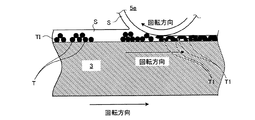
複数のキャリア除去ローラ5a,5b,5c,5d,5eは、画像支持ローラ3に接触し、紙媒体Pにこの画像支持ローラ3上のトナー画像を転写する前に、画像支持ローラ3上のトナー画像に含まれるキャリア液を除去するものである。これらキャリア除去ローラ5a〜eは、画像支持ローラ3上のトナー画像に含まれるキャリア液を除去することで、そのトナー固形分率、すなわちトナー画像に対するトナー粒子の比率を50%以上、好ましくは90%以上とすることができる。各キャリア除去ローラ5a〜5dは、各感光ユニット2a〜dの画像支持ローラ3の回転方向側にそれぞれ配置されている。このキャリア除去ローラ5a〜dは、メインモータ12の駆動力により、この画像支持ローラ3の回転方向と同一方向に回転するものである。この実施例では、キャリア除去ローラ5a〜dの画像支持ローラ3との周速度比、すなわち各キャリア除去ローラ5a〜dの周速度と画像支持ローラ3の周速度との比を一定とする。
The plurality of
キャリア除去ローラ5eは、各感光ユニット2a〜dおよびキャリア除去ローラ5a〜dと、紙媒体Pに画像支持ローラ3上のトナー画像が転写される位置との間で、かつ画像支持ローラ3の回転方向側に配置されている。このキャリア除去ローラ5eは、サブモータ13の駆動力により、この画像支持ローラ3の回転方向と逆方向に回転するものである。ここで、キャリア除去ローラ5eは、その回転方向を画像支持ローラ3の回転方向と逆方向とすると、画像支持ローラ3の回転方向と逆方向とした場合と比較して、画像支持ローラ3上のトナー画像に含まれるキャリア媒体を積極的に除去することができ、この画像支持ローラ3上のトナー画像のトナー固形分率95%以上とすることができる。なお、逆方向とは、回転するローラの接線方向が逆一方向の場合をいう。
The
なお、5fは、各キャリア除去ローラ5a〜dが画像支持ローラ3上のトナー画像から除去したキャリア液を回収する回収ブレードである。なお、この回収されたキャリア液は、例えば、図示しない液体トナータンク内の液体トナーの濃度を調整や、クリーン装置9により、画像支持ローラ3上に紙媒体に転写されずに残ったトナー画像を除去する際に用いられる。
一対の定着ローラ6a,6bは、画像支持ローラ3とバックアップローラ4とにより紙媒体Pに転写されたトナー画像をこの紙媒体Pに定着させるものである。この定着は、トナー画像および紙媒体Pを加熱し、このトナー画像をこの紙媒体Pに対して加圧することで定着するものである。この一対の定着ローラ6a,6bは、互いに接触し、この画像形成装置1により画像を形成することができる紙媒体の最大幅よりも広いニップ長さおよびこの紙媒体Pに対して転写されたトナー画像をこの紙媒体Pに対して十分に加圧することができるニップ圧を形成するものである。この一対の定着ローラ6a,6bは、それぞれヒータ6c,6dにより所定温度(例えば、100〜150度)に加熱されている。一対の定着ローラ6a,6bは、メインモータ12の駆動力により、画像支持ローラ3とバックアップローラ4との間を通過した紙媒体Pをこの一対の定着ローラ6a,6bの間に引き込む方向(定着ローラ6aが画像支持ローラ3の回転方向と同一方向、定着ローラ6bが画像支持ローラ3の回転方向と逆方向)に回転するものである。
The pair of fixing
一対の給紙ローラ7a,7bは、画像支持ローラ3とバックアップローラ4との間に、紙媒体Pを給紙するものである。この一対の給紙ローラ7a,7bは、互いに接触し、この画像形成装置1により画像を形成することができる紙媒体の最大幅よりも広いニップ幅およびこの紙媒体Pを画像支持ローラ3とバックアップローラ4との間に送り出すことができるニップ圧を形成するものである。この一対の給紙ローラ7a,7bは、メインモータ12の駆動力により、紙媒体Pをこの一対の給紙ローラ7a,7bの間に引き込む方向(給紙ローラ7aが画像支持ローラ3の回転方向と同一方向、給紙ローラ7bが画像支持ローラ3の回転方向と逆方向)に回転するものである。
The pair of
制御装置8は、画像形成装置1を運転制御するものであり、特に、紙媒体Pに画像支持ローラ3上のトナー画像を転写する前に、キャリア除去ローラ5a〜eによるこの画像支持ローラ3上のトナー画像に含まれるキャリア液を除去するキャリア除去量を制御するものである。この制御装置8は、入出力部81と、処理部82と、記憶部83とで構成されている。この制御装置8には、上記入力装置84および出力装置85が接続されている。ここで、入力装置84は、入出力部81を介して、画像形成装置1による紙媒体Pへの画像形成の開始指令や、後述する紙媒体の品質や厚みなどの選択を行わせる選択指令などの画像形成装置1の制御指示や、データの入力を行うものである。なお、この入力装置84は、例えばキーボード、マウス、マイク等の入力デバイスである。
The control device 8 controls the operation of the
処理部82は、キャリア除去量制御手段であり、RAM、ROM等のメモリとCPU(Central Processing Unit)とにより構成されている。画像形成装置1による紙媒体Pへの画像の形成の際には、この処理部82が後述する画像形成プログラムを処理部82の図示しないメモリに読み込んで演算を行う。なお、処理部82は、適宜演算途中の数値を記憶部83に格納し、格納した数値を適宜記憶部83から取り出して演算を行う。
The
ここで、この制御装置8には、画像形成装置1により紙媒体Pに形成する画像となる画像データ10が入力される。この画像データ10としては、例えば画像読取装置により読み取られたもの、デジタルカメラなどで撮像されたもの、PCなどのアプリケーション(ワープロソフトやドローソフトなど)により作成されものが含まれる。この制御装置8に入力された画像データ10は、入出力部81を介して出力装置85により表示される。ここで、出力装置85は、CRT(Cathode Ray Tube)や液晶表示装置等である。
Here, the
記憶部83には、この発明にかかる画像形成装置の画像形成方法(キャリア除去量制御方法を含む)が組み込まれた画像形成プログラムが格納されている。ここで、記憶部83は、ハードディスク装置等の固定ディスク装置、フレキシブルディスク、光磁気ディスク装置、またはフラッシュメモリ等の不揮発性のメモリ(CD−ROM等のような読み出しのみが可能な記憶媒体)や、RAM(Random Access Memory)のような揮発性のメモリ等のストレージ手段、あるいはこれらの組み合わせにより構成することができる。また、記憶部83は、処理部82内に設けられていても良いし、他の装置(例えば、データベースサーバ)内に設けられていても良い。また、入力装置84および出力装置85を備えた図示しない端末装置から、画像形成装置1に有線、無線のいずれかの方法でアクセスすることができる構成であっても良い。
The storage unit 83 stores an image forming program in which an image forming method (including a carrier removal amount control method) of the image forming apparatus according to the present invention is incorporated. Here, the storage unit 83 is a fixed disk device such as a hard disk device, a flexible disk, a magneto-optical disk device, or a non-volatile memory such as a flash memory (a storage medium that can only be read such as a CD-ROM), It can be constituted by storage means such as a volatile memory such as RAM (Random Access Memory), or a combination thereof. The storage unit 83 may be provided in the
また、上記画像形成プログラムは、必ずしも単一的に構成されるものに限られず、コンピュータシステムにすでに記憶されているプログラム、例えばOS(Operating System)に代表される別個のプログラムと協働してその機能を達成するものであっても良い。また、処理部82の機能を実現するための画像形成プログラムをコンピュータ読み取り可能な記録媒体に記憶して、この記録媒体に記録された画像形成プログラムをコンピュータシステムに読み込ませ、実行することによりこの発明にかかる画像形成装置1による紙媒体Pへの画像の形成を実行しても良い。なお、ここでいう「コンピュータシステム」とは、OSや周辺機器などのハードウェアを含むものとする。
In addition, the image forming program is not necessarily limited to a single configuration, but in cooperation with a program already stored in a computer system, for example, a separate program represented by an OS (Operating System). The function may be achieved. In addition, the present invention is realized by storing an image forming program for realizing the function of the
ここで、この実施例では、画像形成装置1の後述するキャリア除去ローラ5eを除く各ローラ3,4,21,22a,22b,5a〜dは、メインモータ12と連結されており、このメインモータ12の駆動力により各ローラが同期して回転する。このメインモータ12の回転駆動は、モータ駆動回路11により行われる。なお、この発明はこれに限定されるものではなく、各ローラとモータを対とし、各モータの駆動力によりそれぞれ各ローラを回転させても良い。この場合は、制御装置8は、モータ駆動回路11を介して、各ローラが同期して回転するように、各モータの制御を行う。
In this embodiment, each of the
また、サブモータ13の回転駆動も、メインモータ12と同様にモータ駆動回路11により行われる。サブモータ13は、このモータ駆動回路11を介して、制御装置8により回転速度の制御が行われる。つまり、キャリア除去ローラ5eは、回転速度、ここでは画像支持ローラ3との周速度比が制御装置8により制御される。
Further, the rotation drive of the
また、この実施例では、画像形成装置1の各ヒータ3a,4a,6c,6dによる各ローラ3,4,6a,6bの加熱は、ヒータ駆動回路14により行われる。各ヒータ3a,4a,6c,6dは、このヒータ駆動回路14を介して、制御装置8によりその発熱量の制御が行われる。メインモータ12と連結されており、このメインモータ12の駆動力により各ローラが同期して回転する。このメインモータ12の回転駆動は、モータ駆動回路11により行われる。つまり、各ローラ3,4,6a,6bは、その温度が制御装置8により制御される。
In this embodiment, the
次に、画像形成装置1の動作、すなわち紙媒体Pへの画像の形成(画像形成方法)について説明する。図3は、画像形成装置1による画像形成方法のフロー図である。キャリア除去のフロー図である。図4−1は、バイアスブレード通過時の液体トナーの状態を示す図である。図4−2は、現像時の液体トナーの状態を示す図である。図4−3は、キャリア除去時の画像支持ローラ上のトナー画像の状態を示す図である。図4−4は、転写時の紙媒体のトナー画像の状態を示す図である。図4−5は、定着時の紙媒体のトナー画像の状態を示す図である。
Next, the operation of the
ここで、紙媒体Pには、塗工の度合いや表面粗さに基づいた品質が異なるものがある。例えば、紙媒体Pとしては、キャストコート紙、グロスコート紙、マットコート紙、微塗工紙などがある。この紙媒体Pは、塗工の度合いや、表面粗さによりキャリア液の吸収量が異なる。上記の例では、微塗工紙、マットコート紙、グロスコート紙、キャストコート紙の順で塗工の度合いが低くなり、キャリア液の吸収量が減少する。また、紙媒体Pには、厚さの異なるものがある。この紙媒体Pは、厚さによりキャリア液の吸収できる最大吸収量が異なる。つまり、紙媒体Pの品質および厚さによって、キャリア除去ローラ5a〜eによるトナー画像のキャリア液の除去の際に、このキャリア液を残しておいても、紙媒体Pに吸収され、紙媒体Pに転写されたトナー画像に含まれるキャリア液が著しく低くなる。従って、キャリア液が離型剤として機能しなくなり、オフセット現象が発生する虞がある。そこで、この発明にかかる画像形成装置1では、画像形成媒体である紙媒体Pの品質および厚みに応じて、キャリア除去ローラ5a〜eによるキャリア除去量、この実施例ではキャリア除去ローラ5eの画像支持ローラ3との周速度比を制御する。
Here, some paper media P have different qualities based on the degree of coating and surface roughness. For example, examples of the paper medium P include cast coated paper, gloss coated paper, mat coated paper, and fine coated paper. This paper medium P differs in the amount of carrier liquid absorbed depending on the degree of coating and the surface roughness. In the above example, the degree of coating decreases in the order of finely coated paper, mat coated paper, gloss coated paper, and cast coated paper, and the amount of carrier liquid absorbed decreases. Also, some paper media P have different thicknesses. This paper medium P differs in the maximum absorption amount that the carrier liquid can absorb depending on the thickness. That is, depending on the quality and thickness of the paper medium P, even when the carrier liquid is removed from the toner image by the
まず、ユーザーにより、画像データ10および紙媒体のデータが制御装置8に入力される(ステップST1)。ここでは、制御装置8は、画像形成装置1により紙媒体Pに形成する画像の画像データ10およびこの画像を形成する紙媒体Pのデータを取得する。この紙媒体Pのデータとは、紙媒体Pの品質および厚さである。なお、この紙媒体Pのデータは、画像形成装置1の運転開始前に、制御装置8により画像を形成する紙媒体Pの品質および厚さを出力装置85に複数表示しておき、ユーザーに選択させることで、この制御装置8に入力されても良い。
First, the user inputs the
次に、制御装置8の処理部82は、上記入力された紙媒体Pのデータに基づいて、キャリア除去量を算出する(ステップST2)。ここでは、処理部82は、画像を形成する紙媒体Pの品質および厚さに応じて、キャリア除去量を算出する。例えば、制御装置8の記憶部83に紙媒体Pの品質と厚さに基づくキャリア除去量マップを予め格納しておき、このキャリア除去量マップと、入力された紙媒体Pのデータとに基づいてキャリア除去量を算出する。なお、このキャリア除去量は、トナー画像のトナー固形分率が60%〜95%程度の範囲内となるように、算出される。また、処理部82は、画像を形成する紙媒体Pの品質、すなわち塗工の度合い、表面粗さ、厚さの増加に伴って、キャリア除去量が減少するように算出する。つまり、画像を形成する紙媒体Pの品質、すなわち塗工の度合い、表面粗さ、厚さが増加するにしたがって、定着手段である一対の定着ローラ6a,6bによる紙媒体Pへのトナー画像の定着時におけるこの紙媒体Pのトナー画像に含まれるキャリア液の残存量が増加する。これにより、制御装置8は、紙媒体Pに応じてキャリア液の残存量を任意に制御することができ、オフセット現象を抑制することができるとともに、紙媒体Pに形成された画像の質の低下をも抑制することができる。
Next, the
次に、制御装置8の処理部82は、上記算出されたキャリア除去量に基づいて、キャリア除去ローラ5eの画像支持ローラ3との周速度比を算出する(ステップST3)。ここで、キャリア除去ローラ5eは、その回転方向が画像支持ローラ3の回転方向と反対方向であり、積極的に画像支持ローラ3上のトナー画像に含まれるキャリア液を除去することができる。ところで、その各キャリア除去ローラ5a〜eによるキャリア除去量は、画像支持ローラ3との周速度比を変化することで変化する。ここでは、キャリア除去ローラ5a〜dの画像支持ローラ3との周速度比を一定として、キャリア除去ローラ5eの画像支持ローラ3との周速度比を変化させることで、その各キャリア除去ローラ5a〜eによるキャリア除去量を変化させる。つまり、キャリア除去ローラ5eの画像支持ローラ3との周速度比の増加に伴って、キャリア除去ローラ5e通過後の画像支持ローラ3上のトナー画像に含まれるキャリア液の残存量を減少させることができる。従って、例えば、処理部82は、紙媒体Pがその厚みが一定で、塗工紙の場合周速度比=1、マットコート紙の場合周速度比=2、グロスコート紙の場合周速度比=3、キャストコート紙の場合周速度比=4と算出する。
Next, the
次に、制御装置8の処理部82は、画像形成装置1の運転を開始する(ステップST4)。ここでは、制御装置8に処理部82は、モータ駆動回路11を介して、メインモータ12およびサブモータ13を回転駆動し、各ローラを回転させる。サブモータ13の回転駆動は、この処理部82により算出されたキャリア除去量に基づいて回転駆動され、キャリア除去ローラ5eは算出されたキャリア除去量に基づいて算出された画像支持ローラ3との周速度比で回転する。メインモータ12が回転駆動することにより、図4−1に示すように、各感光ユニット2a〜dの各現像ローラ22aに、各供給ローラ22bを介して各液体トナー貯留室22cに貯留されている単色の液体トナーRTがそれぞれ付着する。ここで、この各現像ローラ22aに付着した単色の液体トナーRTは、トナー粒子Tがキャリア液Sに均一に含まれている。
Next, the
また、処理部82は、各バイアスブレード22dおよび各現像ローラ22aにそれぞれ所定電圧Vbおよび所定電圧Vdを印可する。これにより、同図に示すように、各バイアスブレード22dと各現像ローラ22aとの間に、電界が発生し、トナー粒子Tがプラスに帯電し、液体トナーRTのうち現像ローラ側に移動(電気泳動)する。従って、各バイアスブレード22dを通過した各現像ローラ22a上の単色の液体トナーRTは、トナー粒子Tがキャリア液Sに均一に含まれている状態から現像ローラ側にトナー粒子リッチ層、現像ローラ側と反対側にキャリアリッチ層が形成される状態となる。
The
次に、制御装置8の処理部82は、各感光ユニット2a〜dの各感光ローラ21を除電する(ステップST5)。ここでは、処理部82は、除電装置25を駆動し、各感光ローラ21を除電する。これにより、この各感光ローラ21に形成されていた静電潜像が消去される。
Next, the
次に、制御装置8の処理部82は、各感光ユニット2a〜dの各感光ローラ21を帯電させる(ステップST6)。ここでは、処理部82は、帯電装置23を駆動し、各感光ローラ21を所定電圧Vtに帯電する。
Next, the
次に、制御装置8の処理部82は、各感光ユニット2a〜dの各感光ローラ21を露光する(ステップST7)。ここでは、処理部82は、露光装置24を駆動し、各感光ローラ21を露光し、各感光ローラ21上に、この制御装置8に入力された画像データ10に基づいた静電潜像(図4−2に示すE)を形成するものである。
Next, the
次に、各感光ユニット2a〜dの各感光ローラ21の現像が行われる(ステップST8)。各バイアスブレード22dを通過し、現像ローラ側にトナー粒子リッチ層、現像ローラ側と反対側にキャリアリッチ層が形成される状態となった各現像ローラ22a上の単色の液体トナーRTが各感光ローラ21と接触する。ここで、各感光ローラ21と各現像ローラ22aとでは、電位差、すなわち所定電圧Vdと所定電圧Vtとの差が生じている。従って、単色の液体トナーRTに含まれるプラスに帯電したトナー粒子Tは、図4−2に示すように、各感光ローラ21の静電潜像Eに引き寄せされ、各感光ローラ21上のうち、この静電潜像Eが形成された部分に付着する。これにより、各感光ローラ21の現像が行われ、各感光ローラ21上には、画像データ10に基づいた単色のトナー画像Tiが形成される。
Next, development of each
次に、各感光ユニット2a〜dの各感光ローラ21と画像支持ローラ3との間で一次転写が行われる(ステップST9)。ここでは、各感光ローラ21上にそれぞれ形成された単色のトナー画像Tiが画像支持ローラ3に転写される。例えば、画像支持ローラ3をグランドあるいは所定電圧Vtよりも低い電圧とし、各感光ローラ21と画像支持ローラ3との電位差、すなわち所定電圧Vtと画像支持ローラ3の電圧との差を生じさせる。これにより、単色のトナー画像Tiに含まれるプラスに帯電したトナー粒子Tは、各感光ローラ21の静電潜像Eから画像支持ローラ3に引き寄せられ、画像支持ローラ3に付着し、単色のトナー画像Tiがこの画像支持ローラ3上で重ね合わされ、画像支持ローラ3上に画像データ10に基づいたトナー画像TIが転写され支持される。
Next, primary transfer is performed between the
次に、キャリア除去ローラ5a〜eによるキャリア除去が行われる。(ステップST10)。ここでは、画像支持ローラ3上のトナー画像TIに含まれるキャリア液Sを画像支持ローラ3と接触するキャリア除去ローラ5a〜eに付着させることで除去する。特に、図4−3に示すように、キャリア除去ローラ5eは、この画像支持ローラ3の回転方向と同一方向に回転しているため、画像支持ローラ3上のトナー画像TIに含まれるキャリア液Sを多く掻き取ることができる。このとき、画像支持ローラ3上のトナー画像TIに含まれるトナー粒子Tは、画像支持ローラ3がヒータ3aにより所定温度に加熱されていることで加熱され、半溶融状態、すなわち変形しやすくなっている。従って、この加熱されたトナー粒子Tは、キャリア除去ローラ5a〜eと画像支持ローラ3との間を通過することで押しつぶされ、変形トナー粒子T1となる。変形トナー粒子T1どうしの隙間は、変形前のトナー粒子Tの隙間より狭くなるため、変形前のトナー粒子Tの隙間に存在するキャリア液Sが押し出され、さらにキャリア除去ローラ5a〜eによるトナー画像TIに含まれるキャリア液Sの除去が促進する。ここで、キャリア除去ローラ5eは、この画像支持ローラ3との周速度比が上記算出された周速度比となっているので、キャリア除去ローラ5eを通過した後の画像支持ローラ3上のトナー画像TIに残存するキャリア液Sの量、すなわち残存量は上記算出されたキャリア除去量に基づくものとなる。
Next, carrier removal by the
次に、画像支持ローラ3と紙媒体Pとの間で二次転写が行われる(ステップST11)。ここでは、画像支持ローラ3上のトナー画像TIが紙媒体Pに転写される。上述のように、キャリア除去ローラ5a〜eにより押しつぶされた変形トナー粒子T1は、キャリア除去ローラ5e通過後も、ヒータ3aにより加熱されているため半溶融状態を維持する。従って、図4−4に示すように、画像支持ローラ3上のトナー画像TIが紙媒体Pと接触した際に、変形トナー粒子T1が画像支持ローラ3とバックアップローラ4との間でさらに押しつぶされ、紙媒体Pに付着し、画像支持ローラ3上のトナー画像TIが紙媒体Pに転写される。このとき、紙媒体Pに転写されたトナー画像TIには、キャリア除去ローラ5a〜eによるキャリア除去によるキャリア除去量に基づいた残存量のキャリア媒体Sが存在することとなる。
Next, secondary transfer is performed between the
次に、一対の定着ローラ6a,6bにより、紙媒体Pへのトナー画像TIの定着が行われる(ステップST12)。ここでは、図4−5に示すように、ヒータ6c,6dにより所定温度に加熱された一対の定着ローラ6a,6bの間をトナー画像TIが転写された紙媒体Pが通過することで、この紙媒体Pおよびトナー画像TIを加圧、加熱する。そして、この一対の定着ローラ6a,6bにより、この紙媒体Pにトナー画像TIが定着し、紙媒体Pに画像Wが形成される。ここで、一次転写から二次転写までの間に、紙媒体Pに転写されたトナー画像TIに含まれるキャリア液Sは、紙媒体Pの品質や厚みに応じてこの紙媒体Pに吸収される。しかしながら、紙媒体Pに転写されたトナー画像TIに含まれるキャリア液Sの残存量は、紙媒体Pによるキャリア液Sの吸収量を考慮したキャリア除去量に基づくものである。
Next, the toner image TI is fixed to the paper medium P by the pair of fixing
従って、このトナー画像TIには、紙媒体Pおよびトナー画像TIが一対の定着ローラ6a,6bの間を通過する際に、従来、紙媒体Pに転写されたトナー画像TIが接触するローラに塗布されるシリコーンオイルなどの離型剤と同様の機能、すなわちトナー画像TIが接触する定着ローラ6bにトナー画像TIが付着しようとする付着力を低減することができるキャリア液Sが残存している。
Therefore, the toner image TI is applied to a roller that conventionally contacts the toner image TI transferred to the paper medium P when the paper medium P and the toner image TI pass between the pair of fixing
ここで、キャリア液Sには、シリコーンオイルのみならず、トナー粒子分散剤として変形前のトナー粒子Tに付着する変性シリコーンオイルが含まれている。つまり、キャリア除去ローラ5a〜eにより、紙媒体Pに転写される前のトナー画像TIに含まれるキャリア液Sをすべて除去しようとしても、この変性シリコーンオイルがキャリア液Sとして微量残ることとなる。この変性シリコーンオイルは、トナー粒子Tが半溶融状態で押しつぶされ変形トナー粒子T1となっても、この変形トナー粒子に付着した状態を維持するので、この変性シリコーンオイルによりトナー画像TIが定着ローラ6bに付着しようとする付着力を低減することもできる。これらにより、定着ローラ6bに離型剤を塗布することがなく、オフセット現象を抑制することができる。
Here, the carrier liquid S contains not only silicone oil but also modified silicone oil that adheres to the toner particles T before deformation as a toner particle dispersant. That is, even if all the carrier liquid S contained in the toner image TI before being transferred to the paper medium P is removed by the
また、紙媒体Pに転写されたトナー画像TIに含まれるキャリア液Sを離型剤として用いるので、紙媒体Pに転写されたトナー画像TIに定着ローラ6bに塗布された離型剤が付着する場合と比較して、紙媒体P上に不自然な光沢感の画像Wが形成されることが抑制でき、画像Wの質の低下を抑制することができる。
Further, since the carrier liquid S contained in the toner image TI transferred to the paper medium P is used as a release agent, the release agent applied to the fixing
また、離型剤として機能するキャリア液Sは、紙媒体Pに転写されたトナー画像T1にのみ含まれることとなる。従って、紙媒体Pのトナー画像T1以外の部分には、キャリア液Sは付着しない。これにより、紙媒体Pに残オイル感が残ることを抑制することができる。 Further, the carrier liquid S functioning as a release agent is included only in the toner image T1 transferred to the paper medium P. Accordingly, the carrier liquid S does not adhere to the portion of the paper medium P other than the toner image T1. Thereby, it is possible to suppress the residual oil feeling from remaining on the paper medium P.
また、従来の画像形成装置においては、低分子量のワックス成分が混入された粉体トナーを用いることで、離型剤を塗布することなくオフセット現像を抑制するものがあるが、定着後にも画像Wにこのワックス成分残留してしまい、紙媒体Pに残ワックス感があるという問題がある。これは、従来の画像形成装置においては、定着直前のトナー画像T1に含まれるワックス成分の量を調整することができなく、この粉体トナーに対するワックス成分の混入量をもっともワックスを必要とする紙媒体Pに合わせた量にしなければならないためである。また、残ワックス感を抑制するためにワックス成分の混入量を低下すると画像Wを形成することができる紙媒体が限定されるという問題もある。 Some conventional image forming apparatuses use powder toner mixed with a low molecular weight wax component to suppress offset development without applying a release agent. This wax component remains and the paper medium P has a feeling of residual wax. This is because in the conventional image forming apparatus, the amount of the wax component contained in the toner image T1 immediately before fixing cannot be adjusted, and the amount of the wax component mixed into the powder toner is the paper that most requires the wax. This is because the amount must match the medium P. There is also a problem that the paper medium on which the image W can be formed is limited when the amount of the wax component mixed in is reduced in order to suppress the residual wax feeling.
しかしながら、この発明にかかる画像形成装置1に用いられる液体トナーTRは、揮発しない高粘度のシリコーンオイルであるキャリア液Sによって、固形分であるトナー粒子Tを溶かして分散しているものではなく、トナー粒子Tをそのままの状態で分散させている。従って、トナー粒子Tからキャリア液Sを容易に除去することができ、その除去量を容易に制御することができる。これにより、画像形成媒体に応じて、キャリア液Sの除去量、すなわち画像形成媒体に転写されたトナー画像T1に含まれるキャリア液Sの残存量を容易に制御することができるので、画像Wの残オイル感を抑制することができる。また、画像形成装置1によって画像を形成することができる画像形成媒体の種類を多く、すなわち許容することができる画像形成媒体を広くすることができる。
However, the liquid toner TR used in the
次に、制御装置8の処理部82は、画像Wが形成された紙媒体Pが一対の定着ローラ6a,6bを通過し、画像形成装置1から排紙されると、この画像形成装置1の運転を停止する(ステップST13)。以上により、この画像形成装置1により紙媒体Pに画像Wが形成される。
Next, when the paper medium P on which the image W is formed passes through the pair of fixing
なお、上記実施例では、キャリア除去量制御手段である制御装置8は、キャリア除去ローラ5a〜eの一部(キャリア除去ローラ5e)の画像支持ローラ3との周速度比のみを制御したがこの発明はこれに限定されるものではない。キャリア除去ローラ5a〜eは、その回転方向が画像支持ローラ3の回転方向と反対方向であると、同一方向回転する場合と比較して、キャリア除去量を著しく増加することができ、キャリア除去ローラ5eを通過後の画像支持ローラ3上のトナー画像TIに含まれるキャリア液Sの残存量を減少することができる。また、上述のように、キャリア除去ローラ5a〜eは、画像支持ローラ3との周速度比の増加によっても、キャリア液Sの残存量を減少させることができる。従って、制御装置8は、各キャリア除去ローラ5a〜eの画像支持ローラ3との周速度比を算出されたキャリア除去量に応じて制御しても良い。また、制御装置8は、画像支持ローラ3の回転方向に対する各キャリア除去ローラ5a〜eの回転方向を算出されたキャリア除去量に応じて制御しても良い。
In the above embodiment, the control device 8 which is the carrier removal amount control means controls only the peripheral speed ratio of a part of the
また、キャリア除去ローラ5a〜eは、その電位を画像支持ローラ3の電位よりも高く、かつこの画像支持ローラ3との電位差の増加することで、キャリア液Sの残存量を減少させることができる。従って、制御装置8は、各キャリア除去ローラ5a〜eに電圧を印加し、画像支持ローラ3との電位差を算出されたキャリア除去量に応じて制御しても良い。
Further, the
また、キャリア除去ローラ5a〜eは、画像支持ローラ3に対するニップ圧を増加することで、キャリア液Sの残存量を減少させることができる。従って、各キャリア除去ローラ5a〜eの画像支持ローラ3に対するニップ圧を調整する調整装置を備え、制御装置8は、この調整装置による各キャリア除去ローラ5a〜eの画像支持ローラ3に対するニップ圧を算出されたキャリア除去量に応じて制御しても良い。
Further, the
また、画像支持ローラ3上のトナー画像TIは、その温度によりその粘度が変化する。キャリア除去ローラ5a〜eは、画像支持ローラ3上のトナー画像TIの温度を増加し、トナー画像TIの粘度を低下させることで、このトナー画像TIのキャリア液Sを掻き取りやすくなり、このキャリア液Sの残存量を減少させることができる。従って、制御装置8は、画像支持ローラ3を加熱し、温度を調整するヒータ3aを算出されたキャリア除去量に応じて制御しても良い。
Further, the viscosity of the toner image TI on the
さらに、制御装置8は、上記キャリア除去ローラ5a〜eの回転方向、画像支持ローラ3との周速度比、画像支持ローラ3との電位差、画像支持ローラ3に対するニップ圧、あるいはトナー画像の温度の制御を算出されたキャリア除去量に応じて行っても良い。
Further, the control device 8 controls the rotation direction of the
また、上記実施例では、画像支持ローラ3と接触するキャリア除去ローラ5a〜eの数を一定とし、キャリア除去ローラ5a〜eの一部(キャリア除去ローラ5e)の画像支持ローラ3との周速度比のみをキャリア除去量に応じて制御したがこの発明はこれに限定されるものではない。ここで、画像支持ローラ3に接触するキャリア除去ローラ個数が増加すると、紙媒体Pに転写されたトナー画像TIに残されるキャリア液Sの残存量を減少させることができる。つまり、キャリア除去量は、キャリア除去ローラの個数で制御することができる。従って、例えば、画像形成装置1が一種類の紙媒体Pのみに画像を形成する場合は、この紙媒体Pの品質および厚みに応じたキャリア除去量が一定であるため、この一定のキャリア除去量に応じた個数のキャリア除去ローラを画像支持ローラ3と接触させるようにしても良い。これにより、簡単な構成でキャリア液Sの残存量を制御することができる。
In the above-described embodiment, the number of
また、複数のキャリア除去ローラと、各キャリア除去ローラと画像支持ローラ3との接触、離間をそれぞれ行う着脱装置とを備え、制御装置8は、この各着脱装置による各キャリア除去ローラと画像支持ローラ3との接触、離間を算出されたキャリア除去量に応じて制御しても良い。
The controller 8 includes a plurality of carrier removal rollers, and attachment / detachment devices that respectively contact and separate the carrier removal rollers and the
以上のように、この発明にかかる画像形成装置は、液体トナーを用いる画像読取装置に有用であり、特に、定着手段に離型剤を塗布することなく、オフセット現象を抑制するのに適している。 As described above, the image forming apparatus according to the present invention is useful for an image reading apparatus using liquid toner, and is particularly suitable for suppressing the offset phenomenon without applying a release agent to the fixing unit. .
1 画像形成装置
2a〜d 感光ユニット
21 感光ローラ
22 液体トナー供給装置
22a 現像ローラ
22b 供給ローラ
22c 液体トナー貯留室
22d バイアスブレード
23 帯電装置
24 露光装置
25 除電装置
26 クリーナーブレード
3 画像支持ローラ(転写手段)
3a ヒータ
4 バックアップローラ(転写手段)
4a ヒータ
5a〜e キャリア除去ローラ(キャリア除去手段)
5f 回収ブレード
6a,6b 定着ローラ(定着手段)
6c,6d ヒータ
7a,7b 給紙ローラ
8 制御装置(キャリア除去量制御手段)
81 入出力部
82 処理部
83 記憶部
84 入力装置
85 出力装置
9 クリーン装置
10 画像データ
11 モータ駆動回路
12 メインモータ
13 サブモータ
14 ヒータ駆動回路
P 紙媒体(画像形成媒体)
RT 液体トナー
S キャリア液
T トナー粒子
T1 変形トナー粒子
TI トナー画像
DESCRIPTION OF
6c,
81 Input /
RT liquid toner S carrier liquid T toner particles T1 deformed toner particles TI toner image
Claims (7)
前記転写手段によりトナー画像を転写する前にトナー画像に含まれるキャリア液を除去し、かつ当該転写手段によりトナー画像を転写する前に当該トナー画像に含まれるキャリア液を除去するキャリア除去量を制御するキャリア除去手段と、
前記画像形成媒体に転写された前記キャリア液が含まれるトナー画像を当該画像形成媒体に定着させる定着手段と、
を備えることを特徴とする画像形成装置。 A transfer means for transferring a toner image formed of a liquid toner using a high-viscosity silicone oil that does not volatilize as a carrier liquid to an image forming medium;
The carrier liquid contained in the toner image is removed before the toner image is transferred by the transfer means, and the carrier removal amount for removing the carrier liquid contained in the toner image before the toner image is transferred by the transfer means is controlled. Carrier removing means to perform,
Fixing means for fixing a toner image containing the carrier liquid transferred to the image forming medium to the image forming medium;
An image forming apparatus comprising:
前記キャリア除去手段は、前記画像支持ローラと接触し、前記トナー画像に含まれるキャリア液を除去するキャリア除去ローラを前記キャリア除去量に応じた個数備えることを特徴とする請求項1に記載の画像形成装置。 The transfer unit includes an image support roller that supports at least the toner image until it is transferred to the image forming medium,
2. The image according to claim 1, wherein the carrier removing unit includes a number of carrier removing rollers that come into contact with the image supporting roller and remove a carrier liquid contained in the toner image according to the carrier removal amount. Forming equipment.
前記キャリア除去手段は、前記画像支持ローラと接触し、前記トナー画像に含まれるキャリア液を除去する1以上のキャリア除去ローラと、前記キャリア除去ローラによる前記キャリア除去量を制御するキャリア除去量制御手段とを備えることを特徴とする請求項1に記載の画像形成装置。 The transfer unit includes an image support roller that supports at least the toner image until it is transferred to the image forming medium,
The carrier removing unit is in contact with the image support roller and removes the carrier liquid contained in the toner image. The carrier removing unit controls the amount of carrier removed by the carrier removing roller. The image forming apparatus according to claim 1, further comprising:
前記キャリア除去手段によりキャリア液が除去されたトナー画像を画像形成媒体に転写する転写手順と、
前記画像形成媒体に転写された前記キャリア液が含まれるトナー画像を当該画像形成媒体に定着させる熱定着手順と、
を含むことを特徴とする画像形成方法。 A carrier removal procedure for removing the carrier liquid contained in the toner image formed by the liquid toner using the high-viscosity silicone oil that does not volatilize as the carrier liquid while controlling the carrier removal amount of the carrier liquid;
A transfer procedure for transferring the toner image from which the carrier liquid has been removed by the carrier removing means to an image forming medium;
A thermal fixing procedure for fixing a toner image containing the carrier liquid transferred to the image forming medium to the image forming medium;
An image forming method comprising:
Priority Applications (3)
| Application Number | Priority Date | Filing Date | Title |
|---|---|---|---|
| JP2005359269A JP2007163777A (en) | 2005-12-13 | 2005-12-13 | Image forming apparatus and image forming method |
| US11/556,014 US20070134024A1 (en) | 2005-12-13 | 2006-11-02 | Image forming apparatus and image forming method |
| DE102006052174A DE102006052174A1 (en) | 2005-12-13 | 2006-11-02 | Image forming apparatus and image forming method |
Applications Claiming Priority (1)
| Application Number | Priority Date | Filing Date | Title |
|---|---|---|---|
| JP2005359269A JP2007163777A (en) | 2005-12-13 | 2005-12-13 | Image forming apparatus and image forming method |
Publications (1)
| Publication Number | Publication Date |
|---|---|
| JP2007163777A true JP2007163777A (en) | 2007-06-28 |
Family
ID=38089624
Family Applications (1)
| Application Number | Title | Priority Date | Filing Date |
|---|---|---|---|
| JP2005359269A Pending JP2007163777A (en) | 2005-12-13 | 2005-12-13 | Image forming apparatus and image forming method |
Country Status (3)
| Country | Link |
|---|---|
| US (1) | US20070134024A1 (en) |
| JP (1) | JP2007163777A (en) |
| DE (1) | DE102006052174A1 (en) |
Cited By (1)
| Publication number | Priority date | Publication date | Assignee | Title |
|---|---|---|---|---|
| US8867950B2 (en) | 2011-03-16 | 2014-10-21 | Konica Minolta Business Technologies, Inc. | Wet-type image forming apparatus |
Families Citing this family (3)
| Publication number | Priority date | Publication date | Assignee | Title |
|---|---|---|---|---|
| DE102008048256B4 (en) * | 2008-09-22 | 2016-06-02 | Océ Printing Systems GmbH & Co. KG | Electrophoretic printer or copier |
| JP6287255B2 (en) * | 2014-01-23 | 2018-03-07 | 富士ゼロックス株式会社 | Image forming apparatus, program, and image forming method |
| JP2020003684A (en) * | 2018-06-28 | 2020-01-09 | キヤノン株式会社 | Image forming apparatus |
Citations (3)
| Publication number | Priority date | Publication date | Assignee | Title |
|---|---|---|---|---|
| JP2001305887A (en) * | 2000-04-21 | 2001-11-02 | Pfu Ltd | Liquid development electrophotographic apparatus |
| JP2003091161A (en) * | 2001-09-17 | 2003-03-28 | Ricoh Co Ltd | Liquid image forming apparatus and method for regulating liquid film of developed image in liquid image forming apparatus |
| JP2004004812A (en) * | 2002-03-25 | 2004-01-08 | Ricoh Co Ltd | Liquid developer, image fixing device, and image forming device |
Family Cites Families (4)
| Publication number | Priority date | Publication date | Assignee | Title |
|---|---|---|---|---|
| US6094549A (en) * | 1997-09-26 | 2000-07-25 | Hitachi, Ltd. | Electrograph apparatus enabling removal of offensive substances |
| US6308034B1 (en) * | 1998-03-25 | 2001-10-23 | Pfu Limited | Wet-type electrophotography apparatus, using non-volatile, high viscosity, high concentration liquid toner |
| EP1286230A4 (en) * | 2000-04-21 | 2008-04-09 | Pfu Ltd | Liquid development electrophotographic apparatus |
| US6738592B2 (en) * | 2001-07-06 | 2004-05-18 | Ricoh Company, Ltd. | Image forming apparatus using a developing liquid |
-
2005
- 2005-12-13 JP JP2005359269A patent/JP2007163777A/en active Pending
-
2006
- 2006-11-02 US US11/556,014 patent/US20070134024A1/en not_active Abandoned
- 2006-11-02 DE DE102006052174A patent/DE102006052174A1/en not_active Ceased
Patent Citations (3)
| Publication number | Priority date | Publication date | Assignee | Title |
|---|---|---|---|---|
| JP2001305887A (en) * | 2000-04-21 | 2001-11-02 | Pfu Ltd | Liquid development electrophotographic apparatus |
| JP2003091161A (en) * | 2001-09-17 | 2003-03-28 | Ricoh Co Ltd | Liquid image forming apparatus and method for regulating liquid film of developed image in liquid image forming apparatus |
| JP2004004812A (en) * | 2002-03-25 | 2004-01-08 | Ricoh Co Ltd | Liquid developer, image fixing device, and image forming device |
Cited By (1)
| Publication number | Priority date | Publication date | Assignee | Title |
|---|---|---|---|---|
| US8867950B2 (en) | 2011-03-16 | 2014-10-21 | Konica Minolta Business Technologies, Inc. | Wet-type image forming apparatus |
Also Published As
| Publication number | Publication date |
|---|---|
| US20070134024A1 (en) | 2007-06-14 |
| DE102006052174A1 (en) | 2007-06-21 |
Similar Documents
| Publication | Publication Date | Title |
|---|---|---|
| JP2001194913A (en) | Liquid type image forming device, program recording medium, and liquid type developing device | |
| JP2011059218A (en) | Image forming apparatus | |
| JP2001228717A (en) | Wet developing device and wet image forming device | |
| US8200125B2 (en) | Apparatus and method for imaging forming using modified contact pressure | |
| JP2007163777A (en) | Image forming apparatus and image forming method | |
| JP2002278291A (en) | Liquid developing device and liquid image forming device | |
| JP4653897B2 (en) | Liquid developer coating apparatus, liquid developing apparatus, and image forming apparatus | |
| JP4528201B2 (en) | Fixing liquid applying apparatus and image forming apparatus | |
| JP2004286859A (en) | Image forming apparatus | |
| JP2003280397A (en) | Method and apparatus for wet electrophotographic printing | |
| JP3378778B2 (en) | Wet electrophotographic equipment | |
| JP4774279B2 (en) | Image forming apparatus | |
| JP5201866B2 (en) | Development device | |
| JP3229308B2 (en) | Image formation method | |
| JP2007114241A (en) | Image forming apparatus | |
| JP2007017587A (en) | Image forming apparatus | |
| JP2004170690A (en) | Fixing device and image forming apparatus | |
| JPH1184843A (en) | Developing device | |
| JP2928556B2 (en) | Wet image forming device | |
| JP2003241521A (en) | Wet electrophotographic printing device | |
| JP3243363B2 (en) | Release agent coating device and fixing device provided with the same | |
| JP2009025606A (en) | Image forming apparatus | |
| JP2001109242A (en) | Developing device for one component toner | |
| JP2002132106A (en) | Image forming device | |
| JP2935999B2 (en) | Wet image forming device |
Legal Events
| Date | Code | Title | Description |
|---|---|---|---|
| A621 | Written request for application examination |
Free format text: JAPANESE INTERMEDIATE CODE: A621 Effective date: 20080701 |
|
| A977 | Report on retrieval |
Free format text: JAPANESE INTERMEDIATE CODE: A971007 Effective date: 20101224 |
|
| A131 | Notification of reasons for refusal |
Free format text: JAPANESE INTERMEDIATE CODE: A131 Effective date: 20110104 |
|
| A02 | Decision of refusal |
Free format text: JAPANESE INTERMEDIATE CODE: A02 Effective date: 20110426 |