JP2007163471A - Shield system for inertial measurement unit - Google Patents
Shield system for inertial measurement unit Download PDFInfo
- Publication number
- JP2007163471A JP2007163471A JP2006313193A JP2006313193A JP2007163471A JP 2007163471 A JP2007163471 A JP 2007163471A JP 2006313193 A JP2006313193 A JP 2006313193A JP 2006313193 A JP2006313193 A JP 2006313193A JP 2007163471 A JP2007163471 A JP 2007163471A
- Authority
- JP
- Japan
- Prior art keywords
- circuit breaker
- outer ring
- inner ring
- imu
- elastomer
- Prior art date
- Legal status (The legal status is an assumption and is not a legal conclusion. Google has not performed a legal analysis and makes no representation as to the accuracy of the status listed.)
- Withdrawn
Links
Images


Classifications
-
- F—MECHANICAL ENGINEERING; LIGHTING; HEATING; WEAPONS; BLASTING
- F16—ENGINEERING ELEMENTS AND UNITS; GENERAL MEASURES FOR PRODUCING AND MAINTAINING EFFECTIVE FUNCTIONING OF MACHINES OR INSTALLATIONS; THERMAL INSULATION IN GENERAL
- F16F—SPRINGS; SHOCK-ABSORBERS; MEANS FOR DAMPING VIBRATION
- F16F15/00—Suppression of vibrations in systems; Means or arrangements for avoiding or reducing out-of-balance forces, e.g. due to motion
- F16F15/02—Suppression of vibrations of non-rotating, e.g. reciprocating systems; Suppression of vibrations of rotating systems by use of members not moving with the rotating systems
- F16F15/04—Suppression of vibrations of non-rotating, e.g. reciprocating systems; Suppression of vibrations of rotating systems by use of members not moving with the rotating systems using elastic means
- F16F15/08—Suppression of vibrations of non-rotating, e.g. reciprocating systems; Suppression of vibrations of rotating systems by use of members not moving with the rotating systems using elastic means with rubber springs ; with springs made of rubber and metal
-
- F—MECHANICAL ENGINEERING; LIGHTING; HEATING; WEAPONS; BLASTING
- F16—ENGINEERING ELEMENTS AND UNITS; GENERAL MEASURES FOR PRODUCING AND MAINTAINING EFFECTIVE FUNCTIONING OF MACHINES OR INSTALLATIONS; THERMAL INSULATION IN GENERAL
- F16F—SPRINGS; SHOCK-ABSORBERS; MEANS FOR DAMPING VIBRATION
- F16F15/00—Suppression of vibrations in systems; Means or arrangements for avoiding or reducing out-of-balance forces, e.g. due to motion
- F16F15/10—Suppression of vibrations in rotating systems by making use of members moving with the system
- F16F15/12—Suppression of vibrations in rotating systems by making use of members moving with the system using elastic members or friction-damping members, e.g. between a rotating shaft and a gyratory mass mounted thereon
- F16F15/121—Suppression of vibrations in rotating systems by making use of members moving with the system using elastic members or friction-damping members, e.g. between a rotating shaft and a gyratory mass mounted thereon using springs as elastic members, e.g. metallic springs
- F16F15/124—Elastomeric springs
- F16F15/126—Elastomeric springs consisting of at least one annular element surrounding the axis of rotation
-
- G—PHYSICS
- G01—MEASURING; TESTING
- G01C—MEASURING DISTANCES, LEVELS OR BEARINGS; SURVEYING; NAVIGATION; GYROSCOPIC INSTRUMENTS; PHOTOGRAMMETRY OR VIDEOGRAMMETRY
- G01C19/00—Gyroscopes; Turn-sensitive devices using vibrating masses; Turn-sensitive devices without moving masses; Measuring angular rate using gyroscopic effects
- G01C19/56—Turn-sensitive devices using vibrating masses, e.g. vibratory angular rate sensors based on Coriolis forces
-
- G—PHYSICS
- G01—MEASURING; TESTING
- G01P—MEASURING LINEAR OR ANGULAR SPEED, ACCELERATION, DECELERATION, OR SHOCK; INDICATING PRESENCE, ABSENCE, OR DIRECTION, OF MOVEMENT
- G01P1/00—Details of instruments
- G01P1/02—Housings
- G01P1/023—Housings for acceleration measuring devices
-
- Y—GENERAL TAGGING OF NEW TECHNOLOGICAL DEVELOPMENTS; GENERAL TAGGING OF CROSS-SECTIONAL TECHNOLOGIES SPANNING OVER SEVERAL SECTIONS OF THE IPC; TECHNICAL SUBJECTS COVERED BY FORMER USPC CROSS-REFERENCE ART COLLECTIONS [XRACs] AND DIGESTS
- Y10—TECHNICAL SUBJECTS COVERED BY FORMER USPC
- Y10T—TECHNICAL SUBJECTS COVERED BY FORMER US CLASSIFICATION
- Y10T74/00—Machine element or mechanism
- Y10T74/21—Elements
- Y10T74/2121—Flywheel, motion smoothing-type
- Y10T74/2131—Damping by absorbing vibration force [via rubber, elastomeric material, etc.]
Abstract
Description
本発明は、概ね慣性計測ユニット(IMU)に関し、更に詳細には、IMU遮断器を使用して衝撃及び振動エネルギを減衰させる方法に関する。 The present invention relates generally to inertial measurement units (IMUs), and more particularly to a method for attenuating shock and vibration energy using an IMU circuit breaker.
特定の環境では、機械的に敏感なアッセンブリを、衝撃、振動、及び音響エネルギから遮断する必要がある。多くの用途において、これは、敏感な構成要素を何らかの形態のコンテナ又はハウジング内に配置することによって行われる。デバイスを衝撃、振動、及び音響エネルギから遮断する必要は、デバイスが、慣性計測ユニット(IMU)のセンサ群を含んでいる慣性センサアッセンブリ(ISA)である場合に特に大きい。ISAは、代表的には、3つの軸線での加速度及び/又は回転を検出する慣性センサを含む。通常、3つの加速度計及び3つの回転速度センサは、それらの入力軸線が垂直な関係になるように配置される。これらのセンサは、一般的には、関連する電子装置及びハードウェアとともに、ISAのハウジング内に堅固且つ正確に取り付けられている。一般的には、ISAのハウジングはIMUのコンテナに取り付けられ、IMUは、航空機、ミサイル、又は他の物体等の運搬手段のフレームに堅固且つ正確に取り付けられる。 In certain environments, mechanically sensitive assemblies need to be isolated from shock, vibration, and acoustic energy. In many applications, this is done by placing sensitive components in some form of container or housing. The need to isolate a device from shock, vibration, and acoustic energy is particularly great when the device is an inertial sensor assembly (ISA) that includes a group of inertial measurement units (IMU) sensors. An ISA typically includes an inertial sensor that detects acceleration and / or rotation in three axes. Usually, the three accelerometers and the three rotational speed sensors are arranged so that their input axes are in a vertical relationship. These sensors are typically securely and accurately mounted within the ISA housing along with the associated electronics and hardware. In general, the ISA housing is attached to the container of the IMU, which is firmly and accurately attached to the frame of the vehicle such as an aircraft, missile, or other object.
幾つかの用途では、IMUは、弾道の用途等の極めて高度に動的な環境にさらされる。例えば、このような用途において、IMUを含む発射体は大砲から発射される。従来、慣性センサは、振動遮断器を使用することによって、比較的低レベルの衝撃及び振動からある程度保護されてきた。しかしながら、このような極めて高度に動的な環境は、こうした環境と関連した20000Gもの高い加速度に耐える、小型且つ軽量で更に丈夫な機構を必要とする。従って、衝撃及び振動エネルギを減衰するための機構、特に、慣性センサシステムの性能及び信頼性を向上するために、弾道の用途等の高度に動的な用途で、慣性センサに対して保護を提供する特徴を一体に備えた振動遮断器を提供することが望ましい。 In some applications, the IMU is exposed to a very highly dynamic environment, such as a ballistic application. For example, in such an application, a projectile that includes an IMU is fired from a cannon. In the past, inertial sensors have been protected to some extent from relatively low levels of shock and vibration by using vibration breakers. However, such extremely highly dynamic environments require a small, lightweight and more robust mechanism that can withstand as high as 20000G acceleration associated with such environments. Therefore, it provides protection for inertial sensors in highly dynamic applications such as ballistic applications to improve the performance and reliability of mechanisms for damping impact and vibration energy, especially inertial sensor systems It would be desirable to provide a vibration circuit breaker that includes the features described above.
本発明の以下の簡単な説明は、本発明に独特の新規な幾つかの特徴の理解を容易にするために提供されるものであって、本発明を説明し尽くそうとするものではない。本発明は、明細書全体、特許請求の範囲、添付図面、及び要約の全てを参照することによって、完全に理解されるであろう。 The following brief description of the present invention is provided to facilitate an understanding of some of the novel features unique to the present invention and is not intended to be exhaustive of the invention. The invention may be fully understood by reference to the entire specification, claims, appended drawings, and abstract.
本発明は、概ね慣性計測ユニット(IMU)に関し、更に詳細には、IMU遮断器を使用して衝撃及び振動エネルギを減衰させる方法に関する。
1つの例示の実施例において、遮断器を備えた慣性計測ユニット(IMU)は、突出部分を備えた内面を持つ外リングと、この外リングの内面に隣接する外面に凹所部分を備えた内リングとを含む。突出部分は、少なくとも部分的に凹所部分内に位置決めされ、IMUに大きな回転力が加えられたときに相互係止し、内リングが外リングに対して過度に回転しないように構成される。更に、例示のIMUは、内リングに取り付けられたセンサ群を含んでいてもよい。このセンサ群は、少なくとも一つの慣性センサを有する。例示のIMUは、更に、外リングに取り付けられる、センサ群用のキャビティを形成するカバー部材及びベース部材を含んでいてもよい。このキャビティはキャビティ壁により確定される。
The present invention relates generally to inertial measurement units (IMUs), and more particularly to a method of attenuating shock and vibration energy using an IMU circuit breaker.
In one exemplary embodiment, an inertial measurement unit (IMU) with a circuit breaker includes an outer ring having an inner surface with a protruding portion and an inner portion with a recessed portion on the outer surface adjacent to the inner surface of the outer ring. Including rings. The protruding portion is positioned at least partially within the recessed portion and is configured to interlock when a large rotational force is applied to the IMU so that the inner ring does not rotate excessively with respect to the outer ring. Further, the exemplary IMU may include a group of sensors attached to the inner ring. This sensor group has at least one inertial sensor. The exemplary IMU may further include a cover member and a base member that form a cavity for the group of sensors attached to the outer ring. This cavity is defined by the cavity wall.
更に、センサ群での衝撃及び振動エネルギの減衰作用を補助するため、外リングの少なくとも一部と内リングの少なくとも一部との間にエラストマーが位置決めされていてもよい。幾つかの場合では、エラストマーは、凹所部分の少なくとも一つの側面と突出部分の少なくとも一つの側面との間に位置決めされる。しかしながら他の場合には、エラストマーは、凹所部分の少なくとも一つの側面と突出部分の少なくとも一つの側面との間に位置決めされていなくてもよい。 Furthermore, an elastomer may be positioned between at least a portion of the outer ring and at least a portion of the inner ring to assist in damping the shock and vibration energy in the sensor group. In some cases, the elastomer is positioned between at least one side of the recessed portion and at least one side of the protruding portion. In other cases, however, the elastomer may not be positioned between at least one side of the recessed portion and at least one side of the protruding portion.
別の例示の実施例では、遮断器を備えた慣性計測ユニット(IMU)は、内面を持つ外リングと、この外リングの内面に隣接する外面を持つ内リングと、これらの間に配置されたエラストマーを含む。例示のエラストマーは、外リングの内面の少なくとも一部において、実質的に高さ全体に亘って設けられており、且つ内リングの外面の少なくとも一部において、実質的に高さ全体に亘って設けられている。衝撃発生中に内リングの外面が外リングの内面と係合しようとする場合に、エラストマーとエラストマーとの接触が生じる。幾つかの場合では、エラストマーは、外リングと内リングとの間を延びていてもよく、外リングと内リングとの間に上隙間及び下隙間があってもよい。 In another exemplary embodiment, an inertial measurement unit (IMU) with a circuit breaker is disposed between an outer ring having an inner surface and an inner ring having an outer surface adjacent to the inner surface of the outer ring. Contains elastomer. The exemplary elastomer is provided over substantially the entire height on at least a portion of the inner surface of the outer ring and provided over the entire height of at least a portion of the outer surface of the inner ring. It has been. Contact between the elastomers occurs when the outer surface of the inner ring attempts to engage the inner surface of the outer ring during impact. In some cases, the elastomer may extend between the outer ring and the inner ring, and there may be an upper gap and a lower gap between the outer ring and the inner ring.
更に別の例示の実施例では、慣性計測ユニット(IMU)は、キャビティ壁によって画定されたキャビティを持つコンテナと、外面を持つ内リング及び内面を持つ外リングを備えた遮断器と、少なくとも一つの慣性センサを持つセンサ群とを含む。遮断器の内リングは凹所部分を備え、遮断器の外リングは少なくとも部分的に内リングの凹所部分内に位置決めされる突出部分を備えていてもよい。IMUは、更に、内リングの少なくとも一部分と外リングの少なくとも一部分との間に位置決めされたエラストマーを含んでいてもよい。 In yet another exemplary embodiment, the inertial measurement unit (IMU) includes a container having a cavity defined by a cavity wall, a circuit breaker having an inner ring having an outer surface and an outer ring having an inner surface, and at least one And a sensor group having an inertial sensor. The inner ring of the circuit breaker may comprise a recessed portion and the outer ring of the circuit breaker may comprise a protruding portion positioned at least partially within the recessed portion of the inner ring. The IMU may further include an elastomer positioned between at least a portion of the inner ring and at least a portion of the outer ring.
別の例示の実施例では、遮断器を備えた慣性計測ユニット(IMU)は、凹所部分を備えた内面を持つ外リングと、この外リングの内面に隣接する外面に突出部分を備えた内リングとを含む。回転力が加えられたときに、内リングが外リングに対して過度に回転しないように、突出部分を少なくとも部分的に凹所部分内に位置決めすることによって、突出部分を凹所部分と相互係止させてもよい。更に、外リングの少なくとも一部と内リングの少なくとも一部との間にエラストマーが位置決めされていてもよい。 In another exemplary embodiment, an inertial measurement unit (IMU) with a breaker includes an outer ring having an inner surface with a recessed portion and an inner portion with a protruding portion on the outer surface adjacent to the inner surface of the outer ring. Including rings. Interlocking the protruding portion with the recessed portion by positioning the protruding portion at least partially within the recessed portion so that the inner ring does not rotate excessively relative to the outer ring when a rotational force is applied. It may be stopped. Further, an elastomer may be positioned between at least a portion of the outer ring and at least a portion of the inner ring.
以下の説明は、幾つかの図に亘って同様の要素に同様の参照番号を付した添付図面を参照して読まれるべきである。詳細な説明及び添付図面は、特許請求の範囲に記載した発明を例示する幾つかの実施例を示している。 The following description should be read with reference to the accompanying drawings, in which like elements have like reference numerals throughout the several views. The detailed description and the accompanying drawings illustrate several embodiments that illustrate the invention as claimed.
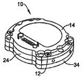
図1は、本発明による例示の慣性計測ユニット(IMU)10を示す斜視図である。例示のIMU10は、IMU10に収容された慣性センサに伝達される衝撃、振動、及び/又は音響エネルギの減少を補助するように設計されており、例えば、20000G以上の大砲による打ち上げなどによる、高度に動的な環境にさらされる場合に慣性センサを保護するため、自動緩衝機構を含んでいる。更に、例示のIMU10は、小型で軽量に設計されているため、従来のIMUよりも大きなG力に耐えることができる。即ち、IMUに実際に作用する力はIMUの質量に正比例するために、小型且つ軽量にすることで、IMU10に作用するG力が減少し、これらの高度に動的な環境での例示のIMU10の性能及び丈夫さのが改善される。更に、例示のIMU10の製造費を、比較的低くすることができる。
FIG. 1 is a perspective view of an exemplary inertial measurement unit (IMU) 10 according to the present invention. The exemplary IMU 10 is designed to assist in reducing the impact, vibration, and / or acoustic energy transmitted to the inertial sensor housed in the IMU 10, such as by launching with a cannon of 20000G or higher. To protect the inertial sensor when exposed to a dynamic environment, an automatic buffering mechanism is included. Further, the exemplary IMU 10 is designed to be small and lightweight, so it can withstand a greater G force than a conventional IMU. That is, since the force actually acting on the IMU is directly proportional to the mass of the IMU, reducing the size and weight reduces the G force acting on the
例示のIMU10は、カバー部材14及びベース部材34を備えるコンテナを含む。これらの部材は、キャビティ壁によって画定されたキャビティを形成する。コンテナは、更に、カバー部材14とベース部材34との間に配置された遮断器24を含んでいる。遮断器24は、幾つかの場合では、キャビティのキャビティ壁の一部を画定する。カバー部材14、ベース部材34、及び遮断器24は、例えばボルトやねじ12等の一つ又はそれ以上のファスナ12を使用して互いに固定されていてもよい。例示の実施例は、カバー部材14、ベース部材34、及び遮断器24を互いに固定するため、4本のねじ12を含んでいる。しかしながら、ファスナ12の数は何本であってもよく、カバー部材14、ベース部材34、及び遮断器24を互いに固定するのに、所望に応じてどのような方法を使用してもよいと考えられる。コンテナは、コンテナ内部に収容されるセンサ群を、衝撃、振動、及び/又は音響エネルギから機械的に遮断するのを補助するために使用されてもよい。幾つかの実施例では、コンテナは、大砲から発射される発射体に固定されてもよい。
The exemplary IMU 10 includes a container that includes a
図1Aは、図1の例示のIMU10を示す分解斜視図である。例示の実施例では、IMU10のコンテナを形成するカバー部材14、遮断器24、及びベース部材34が分解図で示されている。例示の実施例は、更に、カバー部材14と遮断器24との間に配置された第1O−リングシール16又はガスケットを含んでいる。更に、第2O−リングシール32又はガスケットが、遮断器24とベース部材34との間に配置されている。
FIG. 1A is an exploded perspective view illustrating the
例示の実施例は、更に、コンテナのキャビティに配置されたセンサ群36、例えば慣性センサアッセンブリ(ISA)を含むことができる。例示のセンサ群36は、3つの平面内での加速度及び/又は回転を計測することができる。コンテナは、センサ群36に対して保護を提供することができる。例示の実施例では、センサ群36は、キャビティ内において遮断器24の一部に取り付けられる。遮断器24は、センサ群36のところでの衝撃及び振動エネルギの減衰を補助してもよい。
The illustrative embodiment may further include a group of sensors 36, such as an inertial sensor assembly (ISA), disposed in the cavity of the container. The exemplary sensor group 36 can measure acceleration and / or rotation in three planes. The container can provide protection for the sensor group 36. In the illustrated embodiment, the sensor group 36 is attached to a portion of the
例示のセンサ群36は、例えばMEMSジャイロスコープ又はMEMS加速度計等の一つ又はそれ以上の慣性センサを含むことができる。これらの一つ又はそれ以上の慣性センサは、一つ又はそれ以上のプリント配線アッセンブリ(PWA)22及び26に含まれていてもよい。例示の実施例では、センサ群は、2つのPWA22及び26を含む。第1PWA22は、遮断器24の上方に配置され、第2PWA26は、遮断器24の下方に配置される。例示の実施例では、第1PWA22にはプロセッサが取り付けられている。このプロセッサは、IMU10用の電子回路及び制御装置を提供することができる。幾つかの場合では、プロセッサはマイクロプロセッサであってもよい。追加的に、又は別の態様として、第1PWA22には、MEMSジャイロスコープ又はMEMS加速度計等の1つの慣性センサが配置されていてもよい。第2PWA26は、MEMSジャイロスコープ又はMEMS加速度計等の1つの慣性センサを備えてもよい。しかしながら、所望に応じて、プロセッサを第2PWA26に配置し、慣性センサを第1PWA22に配置してよいとも考えられる。更に、センサ群36は、所望の用途に応じて任意の適当な装置又は構成要素が取り付けられた任意の数のPWA22及び26を含んでいてもよい。
The exemplary sensor group 36 can include one or more inertial sensors, such as, for example, a MEMS gyroscope or a MEMS accelerometer. These one or more inertial sensors may be included in one or more printed wiring assemblies (PWA) 22 and 26. In the illustrated embodiment, the sensor group includes two
例示のセンサ群36は、更に、一つ又はそれ以上の支持部材20、28を備えることができる。幾つかの場合では、一つ又はそれ以上の支持部材20、28は、支持リング及び/又は中央支持体を備えていてもよい。幾つかの場合では、中央支持体21及び29は、ワッシャであってもよい。例示の実施例では、支持リング及び中央支持体21を含む第1支持部材20が第1PWA22の上に配置され、支持リング及び中央支持体29を含む第2支持部材28が第2PWA26の下に配置されている。第1支持部材20及び第2支持部材28は、センサ群36を互いに固定するとともにセンサ群36を遮断器24に固定するように構成されている。支持部材20、28は、ボルト又はねじ30等の一つ又はそれ以上のファスナ30用の一つ又はそれ以上の穴を備えていてもよい。更に、遮断器24は、一つ又はそれ以上のファスナ30用の一つ又はそれ以上の穴を設けることによって、センサ群36を遮断器24に固定するように構成されてもよい。例示の実施例では、支持リングを遮断器24に固定するための3本のねじ30が設けられており、中央支持体21及び29を固定するための1本のねじ30が設けられている。しかしながら、所望に応じて任意の数のファスナ30を使用してもよいと考えられる。
The exemplary sensor group 36 can further include one or more support members 20, 28. In some cases, one or more support members 20, 28 may comprise a support ring and / or a central support. In some cases, the central supports 21 and 29 may be washers. In the illustrated embodiment, the first support member 20 including the support ring and the central support 21 is disposed on the first PWA 22, and the second support member 28 including the support ring and the central support 29 is disposed below the
更に、例示の実施例は、センサ群36及びカバー部材14に隣接する入出力フレックステープ18を備えることができる。幾つかの場合では、フレックステープ18の一部がセンサ群36に接続されていてもよい。更に、幾つかの場合では、カバー部材14の開口部を通してフレックステープ18の一部を延長してもよく、慣性データをIMU10の外部に提供あるいは外部から受け取ってもよい。
Further, the illustrated embodiment may include an input / output flex tape 18 adjacent to the sensor group 36 and the
例示のIMU10は、線型加速度及び角加速度の情報等のIMU10の運動に関する慣性データを提供することができる。これらのデータは、IMU10の飛翔及び制御に関する情報をナビゲーションコンピュータに提供してもよい。幾つかの場合では、IMU10は、発射体の飛翔についての案内情報を提供してもよい。その他の場合として、IMU10は、航空機の飛行に関する情報を提供してもよい。より一般的には、所望に応じて、移動可能な任意の対象物に関するデータを提供するために、IMU10を使用してもよい。
The
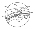
図2は、図1の例示のIMU遮断器24を示す斜視図である。例示のIMU遮断器24は、外面47を持つ内リング42と、内面49が内リング42の外面47に隣接して配置される外リング40とを含んでいる。IMU遮断器24は、更に、内リング42の少なくとも一部と外リング40の少なくとも一部との間に設けられたエラストマー44を含んでいる。幾つかの場合では、エラストマー44は、シリコーンゴムとすることができる。しかしながら、エラストマー44は、エネルギを吸収でき、通常の作動中、及び内リング42と外リング40との間の衝突中の振動及び衝撃を減衰できる任意の材料であってもよいと考えられる。
FIG. 2 is a perspective view illustrating the exemplary
例示の内リング42及び外リング40は、相互係止部分等の回転停止機構を提供するように構成されている。これらの相互係止部分は、内リング42が外リング40に対して過度に回転しないようにするのを補助することができる。これにより、高度に動的な場合中にエラストマーを保護するのを補助してもよい。即ち、回転停止機構により、これらが高度に動的な環境にさらされた場合に、内リング42が外リング40から「スピンアウト」しないようにし、また、エラストマー44がちぎれないようにするのを補助することができる。
The illustrated
例示の回転停止機構は、凹所部分43及び突出部分41を含んでいる。例示の実施例では、内リング42の外面は、少なくとも一つの凹所部分43を備えるように設計されている。外リング40は、内リング42の少なくとも一つの凹所部分43と対応する少なくとも一つの突出部分41を備えた内面を提供するように設計され且つ機械加工されていてもよい。別の態様では、内リング42が少なくとも一つの突出部分41を有し、外リング40が少なくとも一つの対応する凹所部分を備えていてもよいと考えられる。いずれの場合でも、大きな回転力が加えられたときに、凹所部分43及び突出部分41が相互係止することにより、内リング42が外リング40に対して過度に回転しないように、又は実質的に過度に回転しないように、突出部分41が、少なくとも部分的に凹所部分43内に位置決めされていてもよい。こうした大きな回転力は、例えば、IMUを含む発射体に大砲等の銃身で「ライフル作用」を加えることによって与えられる。例示の実施例では、内リング42の外面には4つの凹所部分43が設けられており、外リング40の内面には対応する4つの突出部分41が設けられている。しかしながら、4つの凹所部分43及び突出部分41を使用することは単なる例示であって、所望に応じて任意の数の凹所部分43及び突出部分41を使用してもよいと考えられる。
The exemplary rotation stop mechanism includes a recessed
例示のIMU遮断器24の内リング42は、センサ群が取り付けられるように構成されており、IMU遮断器24の外リング40は、カバー部材及びベース部材が取り付けられるように構成されている。例示の内リング42は、ファスナの挿入を容易にするための一つ又はそれ以上の穴48を設けることによってセンサ群が取り付けられるように構成されている。例示の実施例では、ファスナ用に3つの穴48が設けられている。しかしながら、センサ群の設計に応じて任意の数の穴48を使用してもよいと考えられる。更に、外リング40には、ベース部材及びカバー部材を外リング40に固定するため、一つ又はそれ以上の穴46が設けられていてもよい。例示の実施例では、6個の穴46が設けられている。しかしながら、ベース部材及びカバー部材を外リング40に固定するため、所望に応じて、任意の数の穴46を設けてもよいと考えられる。更に、所望に応じて、センサ群を内リング42に取り付ける又は固定する任意の方法を使用してもよく、カバー部材及びベース部材を外リング40に取り付ける又は固定する任意の方法を使用してもよいと考えられる。
The
図3は、図2の例示のIMU遮断器24を示す分解斜視図である。例示のIMU遮断器24のアッセンブリは、内リング42、エラストマー44、及び外リング40を含む。内リング42及び外リング40は、凹所部分43及び突出部分41を提供するように設計されていてもよい。内リング42及び外リング40を機械加工等で形成した後、内リング42を外リング40内に位置決めしてもよい。次に、エラストマー44を内リング42の少なくとも一部と、外リング40の少なくとも一部との間に設けてもよい。しかしながら、更に、内リング42を外リング40に位置決めする前にエラストマー44を外リング40内に設けてもよく、内リング42及びエラストマー44を外リング40内に位置決めする前にエラストマー44を内リング42の周囲に設けてもよい。あるいは内リング42を外リング40内に位置決めすると同時に又は実質的に同時にエラストマー44を外リング40内に位置決めしてもよいと考えられる。
FIG. 3 is an exploded perspective view illustrating the exemplary
幾つかの場合では、内リング42及び外リング40を、エラストマー44が適用される金型内に配置してもよい。しかしながら、エラストマー44は、所望に応じて、内リング42の全体と外リング40の全体との間に適用されてもよく、又は内リング42の一部と外リング40の一部との間に適用されてもよい。その他の場合では、所望に応じて、噴霧、コーティング、浸漬、型成形によって、又は任意の他の適当な方法によって、エラストマー44を内リング42と外リング40との間に設けてもよい。
In some cases,
例示のIMU遮断器24は、−55℃乃至90℃の温度範囲で使用される。IMU遮断器24は、この温度範囲に亘り、約260ヘルツ(Hz)の固有振動数を備えている。固有振動数の温度による変化は、50Hzの範囲である。ある場合においては、IMU遮断器24の固有振動数は225Hzであり、上記温度範囲に亘り、許容可能な範囲は35Hzである。例示のIMU遮断器24は、更に、上記温度範囲に亘り、3.0乃至7.0の範囲の振動伝達率を備えている。しかしながら、用途に応じて、任意の適当な温度範囲、振動数、又は振動伝達率を使用してもよいと考えられる。
The exemplary
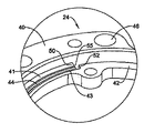
図4は、図2のIMU遮断器24の例示の回転停止機構を示す斜視図である。この例示の回転停止機構は、内リング42の外面の凹所部分43と、外リング40の内面の突出部分41とを含む。凹所部分43及び突出部分41は、突出部分41が少なくとも部分的に凹所部分43内にあるように配置されている。このように整合させた状態では、IMU遮断器24に大きな回転力が加えられたとき、内リング42の凹所部分43の側面52が外リング40の突出部分41の側面50と接触してもよい。例示の回転停止機構により、外リング40及び内リング42は相互係止され、内リング42の外リング40に対する回転が防止され、又は内リング42の外リング40に対する回転が実質的に防止される。
FIG. 4 is a perspective view illustrating an exemplary rotation stop mechanism of the
幾つかの場合では、内リング42と外リング40との相互係止の改良を補助するため、凹所部分43の側面52は、90°の角度で後退していてもよい。突出部分41の側面50は、凹所部分43と同じ所定の角度、この場合には90°で突出していてもよい。更に、幾つかの場合では、凹所部分43の側面52は、90°以上の所定の角度で凹所をなしていてもよい。更に、突出部分の側面50は、対応する角度で突出していてもよい。しかしながら、凹所部分43の側面52及び突出部分41の側面50は、所望に応じて、90°以上又は90°以下の任意の適当な角度を備えていてもよいと考えられる。
In some cases, the
例示のように、エラストマー44は、内リング42の一部と外リング40との間に位置決めすることができ、幾つかの場合においては、領域54に示されるように、エラストマー44は、凹所部分43の側面52及び突出部分41の側面50に隣接して位置決めされていてもよい。エラストマー44は、例えば、高速回転の発生中にIMU遮断器24が底付きした場合に衝撃及び振動エネルギの減衰作用を補助するため、領域54に設けられていてもよい。この場合、内リング42と外リング40との間でエラストマーとエラストマーとの接触が生じる。しかしながら、更に、エラストマー44が一方の表面だけに取り付けられ、これによりエラストマーと金属との接触を生じさせてもよい。或いは、図6に示すように、エラストマーがいずれの表面にも取り付けられておらず、金属と金属との接触が生じるようにしてもよいと考えられる。表面50又は52のうちの少なくとも一方にエラストマー44を設けることによる1つの利点は、高速回転の発生中に、IMUのセンサ群での衝撃及び振動エネルギの減衰作用を高めるということである。
As illustrated, the
図5は、図2のIMU遮断器24の別の例示に係る回転停止機構を示す斜視図である。図4におけるのと同様に、例示のIMU遮断器24は、内リング42の凹所部分43と、外リング40の突出部分41とを含む回転停止機構を備えている。凹所部分43及び突出部分41は、突出部分41が少なくとも部分的に凹所部分43内にあるように位置決めされている。このように整合した状態では、内リング42の凹所部分43の側面52は、外リング40の突出部分41の側面50と接触し、高速回転の発生中に、内リング42が外リング40に対して過度に回転することを阻止又は実質的に阻止する。
FIG. 5 is a perspective view showing a rotation stopping mechanism according to another example of the
しかしながら、幾つかの場合では、領域55に示されているように、凹所部分43の側面52と、突出部分41の側面50との間にエラストマー44が設けられていない。領域55にエラストマー44を設けないのは、設計上の制限及び費用の増大の2つの理由による。エラストマー44が設けられていない場合には、凹所部分43の側面52及び突出部分41の側面50は、例示のIMU遮断器24に高い回転力が加えられた場合、金属と金属との接触が生じる。しかしながら、このような場合中に金属と金属との接触によりセンサ群で減衰される衝撃及び振動エネルギは、図4と比較して小さい。
However, in some cases, as shown in region 55, no
より一般的には、エラストマー44は、所望に応じて、凹所部分43及び突出部分41の側面50及び52の両方に設けられていてもよく、又は凹所部分43の側面52にだけ設けられていてもよく、突出部分41の側面50にだけ設けられていてもよく、又は凹所部分43及び突出部分41の側面50及び52の間に全く設けられていなくてもよいと考えられる。
More generally, the
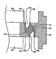
図6は、図2に例示のIMU遮断器を示す概略断面図である。例示のIMU遮断器は、内リング42、外リング40、及びこれらのリング間を延びるエラストマー44を含む。例示のエラストマー44は、所望であれば、内リング42の高さ全体及び外リング40の高さ全体に亘って配置されていてもよい。エラストマーは、上隙間60及び下隙間63を有する。状況によっては、IMU遮断器に並進力が作用し、内リング42と外リング40との間に圧縮を生じさせる。このような圧縮状態では、内リング42のエラストマー領域61が外リング40のエラストマー領域62と接触してもよい。同様に、内リング42のエラストマー領域64が外リング40のエラストマー領域65と接触してもよい。エラストマー44を表面全体に亘って設けることによる1つの利点は、金属と金属との接触又は金属とエラストマーとの接触を防止するのを補助することである。エラストマーとエラストマーとの接触は、衝撃及び振動エネルギをより減衰させることができる。これは、高度に動的な環境で作動する場合に有利である。しかしながら、更に、エラストマー44は、所望に応じて、領域61及び64等の内リング42の全表面、又は領域62及び65等の外リング40の全表面のいずれか一方だけに設けられていてもよいし、内リング又は外リングのいずれにも設けられていなくてもよいと考えられる。
FIG. 6 is a schematic cross-sectional view illustrating the IMU circuit breaker illustrated in FIG. The exemplary IMU circuit breaker includes an
更に、外リング40の内面72は、内リング42の外面70に合わせて同様に成形されていてもよく、先が尖った領域が全くなくてもよい。先が尖った領域が設けられていないことによる一つの利点は、内リング42と外リング40との間を圧縮する並進力が加えられたとき、先が尖った領域が設けられていないために、力が内リング42及び外リング40の表面積全体に亘って分散され、エラストマー44をちぎったり切断したりすることがないということである。これに対し、先が尖った領域が設けられていると、1つの尖った部分に力が集中し、エラストマーをちぎったり切断したりしてしまい、その結果、金属と金属との接触が生じる。
Furthermore, the
更に、例示のエラストマー44は、遮断器中での形状が対称であってもよいし、ほぼ対称であってもよい。形状が対称であるため、エラストマー44の弾性中心が、同様に配置された遮断器の幾何学的中心に置かれるという利点が得られる。更に、エラストマー44は、遮断器の軸線方向剛性及び半径方向剛性を約1:1の比で均衡させてもよい。更に、幾つかの場合では、エラストマー44は、高度に動的な場合における衝撃及び振動エネルギと関連した予想撓み範囲に亘ってばね係数が線型であってもよい。一つの場合として、予想撓み範囲は、約0.0762mm(約0.003インチ)である。しかしながら、エラストマー44は、半径方向で最大約0.3556mm(約0.014インチ)の線型ばね係数即ち剛性を備えていてもよく、軸線方向では、撓み範囲はこれよりも大きいと考えられる。
Further, the
例示の遮断器は、慣性センサに、長さ方向自由度、横方向自由度、軸線方向自由度、ロール自由度、ピッチ自由度、及びヨー自由度等の6度の自由度全てで保護及び/又は減衰を提供してもよい。幾つかの場合では、例示のエラストマー44は、慣性センサに、例えば長さ方向自由度、横方向自由度、及び軸線方向自由度等の3度の自由度で保護及び/又は減衰を提供してもよい。
The exemplary circuit breaker protects and / or protects the inertial sensor with all six degrees of freedom such as longitudinal degrees of freedom, lateral degrees of freedom, axial degrees of freedom, roll degrees of freedom, pitch degrees of freedom, and yaw degrees of freedom. Alternatively, attenuation may be provided. In some cases, the
以上のように、本発明の好ましい実施例を説明してきたが、本技術分野における当業者は、添付した特許請求の範囲内で、更に他の実施例を実施、使用してもよいということを容易に理解するであろう。本明細書によって包含される本発明の多くの利点を以上の説明に記載した。しかしながら、本開示は、多くの点で単なる例示であるということは理解されよう。詳細に関し、特に形状、大ききさ、及び部品の配置に関し、本発明の範囲内で変更を行うことができる。勿論、本発明の範囲は、添付した特許請求の範囲で表現された用語で定義される。 Although preferred embodiments of the present invention have been described above, it will be appreciated by those skilled in the art that other embodiments may be practiced and used within the scope of the appended claims. It will be easy to understand. Many of the advantages of the invention encompassed by the specification have been set forth in the foregoing description. However, it will be understood that this disclosure is merely exemplary in many respects. Changes can be made within the scope of the present invention, particularly with respect to shape, size, and component placement. Of course, the scope of the invention is defined by the terms expressed in the appended claims.
10 慣性計測ユニット(IMU)
12 ファスナ
14 カバー部材
16 第1O−リングシール
24 遮断器
32 第2O−リングシール
34 ベース部材
36 センサ群
10 Inertial measurement unit (IMU)
12
Claims (8)
突出部分を備えた内面を持つ外リングと、
前記外リングの前記内面に隣接する外面を持ち、該外面に凹所部分が設けられた内リングとを備えており、
前記突出部分は、少なくとも部分的に前記凹所部分内に位置決めされることを特徴とする遮断器。 A circuit breaker for an inertial measurement unit (IMU),
An outer ring having an inner surface with a protruding portion;
An outer ring having an outer surface adjacent to the inner surface of the outer ring, and an inner ring provided with a recessed portion on the outer surface;
The circuit breaker characterized in that the protruding portion is positioned at least partially within the recessed portion.
前記凹所部分及び前記突出部分は、前記内リングが前記外リングに対して過度に回転しないように、少なくとも部分的に相互係止することを特徴とする遮断器。 The circuit breaker according to claim 1,
The circuit breaker characterized in that the recessed portion and the protruding portion are at least partially interlocked so that the inner ring does not rotate excessively with respect to the outer ring.
前記凹所部分は少なくとも一つの側面を有し、前記突出部分は、前記内リングが前記外リングに対して過度に回転しないように接触する少なくとも一つの側面を有することを特徴とする遮断器。 The circuit breaker according to claim 2, wherein
The breaker portion has at least one side surface, and the protruding portion has at least one side surface that contacts the inner ring so as not to rotate excessively with respect to the outer ring.
前記外リングの少なくとも一部と前記内リングの少なくとも一部との間にエラストマーが位置決めされていることを特徴とする遮断器。 The circuit breaker according to claim 3, wherein
The circuit breaker characterized in that an elastomer is positioned between at least a part of the outer ring and at least a part of the inner ring.
前記エラストマーは、前記凹所部分の前記少なくとも一つの側面と、前記突出部分の前記少なくとも一つの側面との間に位置決めされていることを特徴とする遮断器。 The circuit breaker according to claim 4, wherein
The circuit breaker characterized in that the elastomer is positioned between the at least one side surface of the recessed portion and the at least one side surface of the protruding portion.
前記エラストマーは、前記凹所部分の前記少なくとも一つの側面と、前記突出部分の前記少なくとも一つの側面との間に位置決めされていないことを特徴とする遮断器。 The circuit breaker according to claim 4, wherein
The circuit breaker according to claim 1, wherein the elastomer is not positioned between the at least one side surface of the recessed portion and the at least one side surface of the protruding portion.
前記内リングに取り付けられたセンサ群を含み、該センサ群は少なくとも一つの慣性センサを有することを特徴とする遮断器。 The circuit breaker according to claim 1, further comprising:
A circuit breaker comprising a group of sensors attached to the inner ring, the group of sensors having at least one inertial sensor.
前記外リングに取り付けられ、前記センサ群用のキャビティを形成するカバー部材及びベース部材を含み、前記キャビティはキャビティ壁によって画定されることを特徴とする遮断器。 The circuit breaker according to claim 7, further comprising:
A circuit breaker comprising a cover member and a base member attached to the outer ring and forming a cavity for the sensor group, the cavity defined by a cavity wall.
Applications Claiming Priority (1)
| Application Number | Priority Date | Filing Date | Title |
|---|---|---|---|
| US11/164,355 US20070113702A1 (en) | 2005-11-18 | 2005-11-18 | Isolation system for an inertial measurement unit |
Publications (2)
| Publication Number | Publication Date |
|---|---|
| JP2007163471A true JP2007163471A (en) | 2007-06-28 |
| JP2007163471A5 JP2007163471A5 (en) | 2009-12-03 |
Family
ID=37887794
Family Applications (1)
| Application Number | Title | Priority Date | Filing Date |
|---|---|---|---|
| JP2006313193A Withdrawn JP2007163471A (en) | 2005-11-18 | 2006-11-20 | Shield system for inertial measurement unit |
Country Status (4)
| Country | Link |
|---|---|
| US (1) | US20070113702A1 (en) |
| EP (1) | EP1788277B1 (en) |
| JP (1) | JP2007163471A (en) |
| DE (1) | DE602006010502D1 (en) |
Cited By (6)
| Publication number | Priority date | Publication date | Assignee | Title |
|---|---|---|---|---|
| JP2014526998A (en) * | 2011-09-02 | 2014-10-09 | 深▲せん▼市大▲じゃん▼創新科技有限公司 | Unmanned aerial inertial measurement module |
| JP2016534348A (en) * | 2013-09-02 | 2016-11-04 | ノースロップ グルマン リテフ ゲーエムベーハーNorthrop Grumman LITEF GmbH | Movement monitoring system and movement monitoring method |
| KR101724332B1 (en) * | 2015-12-16 | 2017-04-07 | 국방과학연구소 | Inertial measurement unit |
| US10030974B2 (en) | 2015-04-07 | 2018-07-24 | SZ DJI Technology Co., Ltd. | System and method for providing a simple and reliable inertia measurement unit (IMU) |
| CN111197981A (en) * | 2018-11-16 | 2020-05-26 | 北京自动化控制设备研究所 | Double-shaft rotating device for integrally shielding inertia combination |
| KR20240011997A (en) | 2022-07-20 | 2024-01-29 | 국방과학연구소 | Inertial sensor assembly and inertial sensor block unit for the inertial sensor assembly |
Families Citing this family (22)
| Publication number | Priority date | Publication date | Assignee | Title |
|---|---|---|---|---|
| US7404324B2 (en) * | 2005-08-19 | 2008-07-29 | Honeywell International Inc. | Gunhard shock isolation system |
| US8266960B2 (en) | 2009-04-10 | 2012-09-18 | Honeywell International Inc. | Systems and methods for potted shock isolation |
| US8573056B1 (en) * | 2010-06-04 | 2013-11-05 | The United States Of America As Represented By The Secretary Of The Army | Guided projectile with motion restricting piezoelectric actuator |
| CN102121829B (en) | 2010-08-09 | 2013-06-12 | 汪滔 | Miniature inertia measurement system |
| US9339224B2 (en) | 2011-02-24 | 2016-05-17 | Rochester Institute Of Technology | Event dosimeter devices and methods thereof |
| US10292445B2 (en) | 2011-02-24 | 2019-05-21 | Rochester Institute Of Technology | Event monitoring dosimetry apparatuses and methods thereof |
| US8931765B2 (en) * | 2012-09-27 | 2015-01-13 | Honeywell International Inc. | Systems and methods for high frequency isolation |
| US9664516B2 (en) | 2014-04-25 | 2017-05-30 | SZ DJI Technology Co., Ltd. | Inertial sensing device |
| US20160054355A1 (en) * | 2014-08-20 | 2016-02-25 | Honeywell International Inc. | Compact inertial measurement unit with interface adapter |
| US9541568B2 (en) * | 2014-10-08 | 2017-01-10 | Honeywell International Inc. | Systems and methods for isolated sensor device protection |
| GB2536037A (en) | 2015-03-05 | 2016-09-07 | Atlantic Inertial Systems Ltd | Anti-vibration mounting system |
| CN104833821B (en) * | 2015-05-07 | 2017-11-03 | 深圳导远科技有限公司 | The inertial measurement cluster of vibration isolation in annular suspension formula |
| US9625284B2 (en) * | 2015-09-04 | 2017-04-18 | Honeywell International Inc | Shock mount in environment sensor protector for non-isolated systems |
| US20170350913A1 (en) * | 2016-06-03 | 2017-12-07 | Green Power Monitoring Systems, Inc. | Suspension System |
| CN108050191B (en) * | 2017-12-13 | 2020-07-03 | 中国飞机强度研究所 | Annular metal rubber vibration isolator |
| US10648530B2 (en) * | 2018-02-08 | 2020-05-12 | Topcon Positioning Systems, Inc. | Wedged three-axis inertial sensor damper-suspension |
| GB2575978A (en) * | 2018-07-30 | 2020-02-05 | Innalabs Ltd | Gyroscope |
| US11312619B1 (en) | 2018-10-04 | 2022-04-26 | EngeniusMicro, LLC | Methods of manufacture of microisolators and devices for mechanical isolation or mechanical damping of microfabricated inertial sensors |
| JP6545918B1 (en) * | 2019-05-22 | 2019-07-17 | Imv株式会社 | Acceleration sensor core unit, method for preventing deflection of substrate on which acceleration sensor is mounted |
| CN110425250A (en) * | 2019-07-17 | 2019-11-08 | 北京自动化控制设备研究所 | Integrated vibration-proof structure for MEMS inertial instrument system |
| US11459231B2 (en) | 2020-11-23 | 2022-10-04 | United States Government As Represented By The Secretary Of The Army | Microelectronic isolation system |
| CN113090709B (en) * | 2021-04-12 | 2024-04-09 | 西安航弓机电科技有限公司 | Inertial module with vibration isolation structure |
Family Cites Families (53)
| Publication number | Priority date | Publication date | Assignee | Title |
|---|---|---|---|---|
| FR663418A (en) * | 1928-02-17 | 1929-08-21 | Jules Richard Sa Des Ets | Elastic fixation device for precision devices |
| US3167294A (en) * | 1961-01-09 | 1965-01-26 | Zenas B Andrews | Missile launcher shock absorber |
| US3483623A (en) * | 1968-08-20 | 1969-12-16 | George R Kruzell | Shock-proof telescopic gun sight mount |
| FR2058451A5 (en) * | 1969-09-05 | 1971-05-28 | Aquitaine Petrole | |
| US3843108A (en) * | 1973-01-31 | 1974-10-22 | Singer Co | Vibration and shock isolated gyroscope assembly |
| US3933012A (en) * | 1973-07-13 | 1976-01-20 | Trw Inc. | Torque absorber for submergible pumps |
| US4026054A (en) * | 1976-02-02 | 1977-05-31 | Snyder Wesley L | Laser aiming system for weapons |
| US4178811A (en) * | 1977-06-15 | 1979-12-18 | Wallace Murray Corporation | Meta reinforced plastic damper hub |
| US4114246A (en) * | 1977-06-29 | 1978-09-19 | Houdaille Industries, Inc. | Method of and means for making tuned viscous torsional vibration dampers |
| US4228664A (en) * | 1978-11-08 | 1980-10-21 | Douville-Johnston Corporation | Flexible drive coupling |
| GB2068503B (en) * | 1980-01-25 | 1983-07-06 | Concentric Pumps Ltd | Vibration dampers |
| US4494072A (en) * | 1980-04-21 | 1985-01-15 | Exploration Logging, Inc. | Well logging apparatus with replaceable sensor carrying insulating sleeve disposed in rotation restrained position around a drill string |
| JPS5812747U (en) * | 1981-07-20 | 1983-01-26 | 小松ゼノア株式会社 | Vibration isolator |
| US4524675A (en) * | 1982-08-03 | 1985-06-25 | The United States Of America As Represented By The Secretary Of The Army | Detachably connectable sight assembly for a small defense weapon |
| DE3403858A1 (en) * | 1984-02-03 | 1985-08-14 | Metzeler Kautschuk GmbH, 8000 München | PLASTIC RING RING FASTENABLE ON A SHAFT FOR A TURN VIBRATION DAMPER |
| SE459993B (en) * | 1985-01-25 | 1989-08-28 | Philips Norden Ab | DEVICE FOR POWER SUPPLY BY A CANON INCLUDING A FOLLOWING UNIT WITH RADAR TRANSMITTER / RECEIVER AND ANTENNA ORGAN |
| US4581933A (en) * | 1985-02-04 | 1986-04-15 | Penn Airborne Products Company | Aircraft casing indicator seal |
| DE3514268A1 (en) * | 1985-04-19 | 1986-10-23 | Metzeler Kautschuk GmbH, 8000 München | PRELVETABLE AND HYDRAULIC DAMPED BEARING ELEMENT |
| US5425287A (en) * | 1986-08-29 | 1995-06-20 | Beattie; James C. | System for damping vibration of crankshafts and the like |
| US5299468A (en) * | 1989-08-04 | 1994-04-05 | Withers Graham R | Elastomeric vibrational dampers |
| US4936190A (en) * | 1989-09-20 | 1990-06-26 | The United States Of America As Represented By The Secretary Of The Army | Electrooptical muzzle sight |
| US4972619A (en) * | 1989-11-29 | 1990-11-27 | Eckert Kenneth I | Rifle sighting apparatus |
| US5040764A (en) * | 1990-09-28 | 1991-08-20 | The United States Of America As Represented By The Secretary Of The Navy | Low frequency vibration absorber |
| US5237871A (en) * | 1990-10-12 | 1993-08-24 | Teledyne Industries Incorporated | Vibration attenuation assembly with venting passageway |
| US5305981A (en) * | 1991-10-31 | 1994-04-26 | Honeywell Inc. | Multiaxis vibration isolation system |
| US5267720A (en) * | 1991-12-06 | 1993-12-07 | Sperry Marine Inc. | Structureborne noise isolator |
| US5231893A (en) * | 1991-12-10 | 1993-08-03 | Simpson Industries, Inc. | Dual mode damper |
| US5189245A (en) * | 1992-01-02 | 1993-02-23 | The United States Of America As Represented By The Secretary Of The Army | Thermally and mechanically stable muzzle reference system collimator assembly |
| US5368271A (en) * | 1992-03-02 | 1994-11-29 | Hughes Aircraft Company | Gimbal vibration isolation system |
| DE4209610C1 (en) * | 1992-03-25 | 1993-03-11 | Fa. Carl Freudenberg, 6940 Weinheim, De | |
| DE4238512C1 (en) * | 1992-11-14 | 1994-01-20 | Deutsche Aerospace | Inertial stabilization system |
| US5363700A (en) * | 1992-11-17 | 1994-11-15 | Honeywell Inc. | Skewed axis inertial sensor assembly |
| US5360236A (en) * | 1992-12-14 | 1994-11-01 | Honeywell Inc. | Apparatus and methods for mounting an inertial sensor chassis to an aircraft support frame |
| US5474499A (en) * | 1993-07-12 | 1995-12-12 | The United States Of America As Represented By The Secretary Of The Navy | Flexible drive shaft coupling |
| US5389746A (en) * | 1994-06-30 | 1995-02-14 | The United States Of America As Represented By The Secretary Of The Navy | Submarine hull structures providing acoustically isolated hull openings |
| US5529277A (en) * | 1994-09-20 | 1996-06-25 | Ball Corporation | Suspension system having two degrees of rotational freedom |
| JPH09303354A (en) * | 1996-05-21 | 1997-11-25 | Kioritz Corp | Slipping off preventing structural body and bush cutter equipped therewith |
| US5947240A (en) * | 1997-02-03 | 1999-09-07 | Honeywell, Inc. | Load vibration isolation apparatus |
| US5803213A (en) * | 1997-02-03 | 1998-09-08 | Honeywell Inc. | Heavy load vibration isolation apparatus |
| US5878980A (en) * | 1997-02-05 | 1999-03-09 | Hughes Electronics Corporation | Attenuation ring |
| US5890569A (en) * | 1997-06-06 | 1999-04-06 | Honeywell Inc. | Vibration isolation system for an inertial sensor assembly |
| US6113030A (en) * | 1997-11-17 | 2000-09-05 | Lord Corporation | Readily changeable isolator and method of assembly thereof |
| US6237463B1 (en) * | 1999-06-14 | 2001-05-29 | Honeywell Inc. | Isolation system mount for mounting sensitive electronic equipment to non-recoiled artillery |
| US6202961B1 (en) * | 2000-03-21 | 2001-03-20 | Csa Engineering | Passive, multi-axis, highly damped, shock isolation mounts for spacecraft |
| US6808455B1 (en) * | 2000-05-03 | 2004-10-26 | Michael Solorenko | Torsional shock absorber for a drill string |
| US6522992B1 (en) * | 2000-05-24 | 2003-02-18 | American Gnc Corporation | Core inertial measurement unit |
| US6578682B2 (en) * | 2001-04-26 | 2003-06-17 | Honeywell International Inc. | Compact vibration isolation system for an inertial sensor assembly |
| US6993989B2 (en) * | 2002-04-26 | 2006-02-07 | Denso Corporation | Starting apparatus |
| US6959682B2 (en) * | 2002-09-05 | 2005-11-01 | General Motors Corporation | Engine balancer with chain drive vibration isolation |
| US20040150144A1 (en) * | 2003-01-30 | 2004-08-05 | Honeywell International Inc. | Elastomeric vibration and shock isolation for inertial sensor assemblies |
| US6704619B1 (en) * | 2003-05-24 | 2004-03-09 | American Gnc Corporation | Method and system for universal guidance and control of automated machines |
| US6879875B1 (en) * | 2003-09-20 | 2005-04-12 | American Gnc Corporation | Low cost multisensor high precision positioning and data integrated method and system thereof |
| US7448306B2 (en) * | 2004-12-21 | 2008-11-11 | Honeywell International Inc. | Pointing device inertial isolation and alignment mounting system |
-
2005
- 2005-11-18 US US11/164,355 patent/US20070113702A1/en not_active Abandoned
-
2006
- 2006-11-20 DE DE602006010502T patent/DE602006010502D1/en active Active
- 2006-11-20 EP EP06124381A patent/EP1788277B1/en not_active Expired - Fee Related
- 2006-11-20 JP JP2006313193A patent/JP2007163471A/en not_active Withdrawn
Cited By (13)
| Publication number | Priority date | Publication date | Assignee | Title |
|---|---|---|---|---|
| JP2016117485A (en) * | 2011-09-02 | 2016-06-30 | 深▲せん▼市大▲じゃん▼創新科技有限公司 | Unmanned aircraft inertia measurement module |
| JP2014526998A (en) * | 2011-09-02 | 2014-10-09 | 深▲せん▼市大▲じゃん▼創新科技有限公司 | Unmanned aerial inertial measurement module |
| US9772343B2 (en) | 2011-09-02 | 2017-09-26 | SZ DJI Technology Co., Ltd | Inertia measurement module for unmanned aircraft |
| US9841432B2 (en) | 2011-09-02 | 2017-12-12 | SZ DJI Technology Co., Ltd | Inertia measurement module for unmanned aircraft |
| US10591504B2 (en) | 2011-09-02 | 2020-03-17 | SZ DJI Technology Co., Ltd. | Inertia measurement module for unmanned aircraft |
| US11293937B2 (en) | 2011-09-02 | 2022-04-05 | SZ DJI Technology Co., Ltd. | Inertia measurement module for unmanned aircraft |
| JP2016534348A (en) * | 2013-09-02 | 2016-11-04 | ノースロップ グルマン リテフ ゲーエムベーハーNorthrop Grumman LITEF GmbH | Movement monitoring system and movement monitoring method |
| US11112244B2 (en) | 2015-04-07 | 2021-09-07 | SZ DJI Technology Co., Ltd. | System and method for providing a simple and reliable inertia measurement unit (IMU) |
| US10030974B2 (en) | 2015-04-07 | 2018-07-24 | SZ DJI Technology Co., Ltd. | System and method for providing a simple and reliable inertia measurement unit (IMU) |
| US10627233B2 (en) | 2015-04-07 | 2020-04-21 | SZ DJI Technology Co., Ltd. | System and method for providing a simple and reliable inertia measurement unit (IMU) |
| KR101724332B1 (en) * | 2015-12-16 | 2017-04-07 | 국방과학연구소 | Inertial measurement unit |
| CN111197981A (en) * | 2018-11-16 | 2020-05-26 | 北京自动化控制设备研究所 | Double-shaft rotating device for integrally shielding inertia combination |
| KR20240011997A (en) | 2022-07-20 | 2024-01-29 | 국방과학연구소 | Inertial sensor assembly and inertial sensor block unit for the inertial sensor assembly |
Also Published As
| Publication number | Publication date |
|---|---|
| EP1788277A2 (en) | 2007-05-23 |
| DE602006010502D1 (en) | 2009-12-31 |
| US20070113702A1 (en) | 2007-05-24 |
| EP1788277A3 (en) | 2007-08-08 |
| EP1788277B1 (en) | 2009-11-18 |
Similar Documents
| Publication | Publication Date | Title |
|---|---|---|
| JP2007163471A (en) | Shield system for inertial measurement unit | |
| US7404324B2 (en) | Gunhard shock isolation system | |
| US9068622B2 (en) | Shock-isolation structure | |
| AU2004252398B2 (en) | Elastomeric vibration and shock isolation for inertial sensor assemblies | |
| US9069001B2 (en) | Systems and methods for potted shock isolation | |
| CA2445015C (en) | Compact vibration isolation system for an inertial sensor assembly | |
| CN111397601B (en) | Little inertia measurement unit shock-resistant damping structure and damping system | |
| EP2604974B1 (en) | Micro inertial measurement system | |
| US20140001687A1 (en) | Annular isolator with secondary features | |
| EP3009846B1 (en) | Isolated sensor device comprising an isolator and an impact interface | |
| US9625284B2 (en) | Shock mount in environment sensor protector for non-isolated systems | |
| KR100934378B1 (en) | Shock mount for installing gyro sensor | |
| WO2018088028A1 (en) | Vibration control device and unmanned aircraft | |
| WO2002027209A2 (en) | Radial snubber for vibration isolator | |
| KR101724332B1 (en) | Inertial measurement unit | |
| CN108146645A (en) | A kind of IMU mechanisms and unmanned plane | |
| EP0675825B1 (en) | Gyro nutation damper | |
| CN107628261A (en) | A kind of IMU barometers component and unmanned plane |
Legal Events
| Date | Code | Title | Description |
|---|---|---|---|
| A521 | Request for written amendment filed |
Free format text: JAPANESE INTERMEDIATE CODE: A523 Effective date: 20091016 |
|
| A621 | Written request for application examination |
Free format text: JAPANESE INTERMEDIATE CODE: A621 Effective date: 20091016 |
|
| A761 | Written withdrawal of application |
Free format text: JAPANESE INTERMEDIATE CODE: A761 Effective date: 20100507 |