JP2007149337A - Optical disk recording device - Google Patents
Optical disk recording device Download PDFInfo
- Publication number
- JP2007149337A JP2007149337A JP2007024978A JP2007024978A JP2007149337A JP 2007149337 A JP2007149337 A JP 2007149337A JP 2007024978 A JP2007024978 A JP 2007024978A JP 2007024978 A JP2007024978 A JP 2007024978A JP 2007149337 A JP2007149337 A JP 2007149337A
- Authority
- JP
- Japan
- Prior art keywords
- test
- writing process
- test writing
- area
- disc
- Prior art date
- Legal status (The legal status is an assumption and is not a legal conclusion. Google has not performed a legal analysis and makes no representation as to the accuracy of the status listed.)
- Pending
Links
Images


Abstract
Description
本発明は記録可能な光ディスクの記録再生装置に関し、特に書き込み時に必要なのレーザパワーの試し書き処理に関する。 The present invention relates to a recordable / reproducing apparatus for a recordable optical disc, and more particularly to a test writing process for laser power necessary for writing.
従来、CD−R等の記録可能な光ディスクの記録時には、光ディスクに設けられたテスト記録領域であるPCA(PowerCalibrationArea)に試し書きを行い、好適な記録条件を求めた後、記録処理を行っていた(例えば、非特許文献1参照)。このPCAには複数個のパーティションが存在しているが、各々のパーティションは一度使用すると再使用できないため、記録処理前に好適な記録条件を求めることができる回数、すなわち、好適な記録条件を検出した上で記録できる回数は限られていた。このため、1回の記録条件検出に使用するパーティションを1パーティションとすることで、記録条件検出の可能な回数が少なくならないよう工夫をしていた。また、好適な記録条件を予めディスクに記録しておくことで、記録条件検出の処理を省略することも行われていた。 Conventionally, when recording on a recordable optical disc such as a CD-R, trial writing is performed on a PCA (Power Calibration Area) which is a test recording area provided on the optical disc, and a recording process is performed after obtaining suitable recording conditions. (For example, refer nonpatent literature 1). This PCA has a plurality of partitions, but since each partition cannot be reused once it is used, the number of times that a suitable recording condition can be obtained before the recording process, that is, a suitable recording condition is detected. In addition, the number of times that recording was possible was limited. For this reason, the number of times that the recording condition can be detected is reduced by setting one partition to be used for detecting the recording condition to one partition. In addition, by recording suitable recording conditions on the disc in advance, the recording condition detection process has been omitted.
このような記録条件の検出方法は、CD−RW、DVD−R/RW、DVD+R/RWの各ディスクに対し記録処理を行う際にも実施されていた。DVD+R/RWディスクはパーティションの数を増やすなどの観点からディスクの内周側と外周側の両方にテスト記録領域(InnerDriveArea,OuterDriveArea)を有する構成をとっている。 Such a recording condition detection method has also been implemented when recording processing is performed on CD-RW, DVD-R / RW, and DVD + R / RW discs. The DVD + R / RW disc has a configuration having test recording areas (InnerDriveArea, OuterDriveArea) on both the inner and outer peripheral sides of the disc from the viewpoint of increasing the number of partitions.
記録可能な光ディスクに対する記録処理において、光ディスク装置が記憶している、または、各々の光ディスクに予め記録されているデフォルトの記録条件(標準的な特性を有するディスクに対し、標準的な特性を有する装置で記録する際の記録条件)に従って記録処理を行った場合であっても、記録対象ディスクの品質が悪い場合には、適切なデータ記録が行えない問題があった。このような品質の悪いディスクに対する適切な記録条件を検出ことが第一の課題である。 In a recording process for a recordable optical disk, a default recording condition stored in the optical disk apparatus or recorded in advance on each optical disk (an apparatus having standard characteristics for a disk having standard characteristics) Even when the recording process is performed in accordance with the recording conditions when recording with (2), there is a problem that appropriate data recording cannot be performed if the quality of the recording target disk is poor. The first problem is to detect an appropriate recording condition for such a poor quality disc.
また、従来の記録条件検出方法では、品質の悪いディスクに対しても1回の試し書き時にはPCAの1パーティションしか使用していなかったため、様々な記録パラメータを考慮した好適な記録条件を求めることができなかった。従来の方法では検出できなかった品質の悪いディスクに対する好適な記録条件を検出することが本願の第2の課題である。 In addition, in the conventional recording condition detection method, only one partition of PCA is used at the time of one trial writing even for a low-quality disc, so that it is possible to obtain a suitable recording condition in consideration of various recording parameters. could not. It is the second problem of the present application to detect a suitable recording condition for a disk of poor quality that could not be detected by a conventional method.
上記第一の課題は、ディスクの品質を確かめるための第一の試し書き処理によって得た結果により、ディスクの品質がある一定の基準値よりも悪い場合は、試し書きのパラメータを増やす第二の試し書きを行うことにより、レーザの書き込み精度を上げることができる。 The first problem is that, if the disc quality is lower than a certain reference value according to the result obtained by the first trial writing process for confirming the quality of the disc, the second parameter is increased. By performing trial writing, the laser writing accuracy can be increased.
上記第二の課題は、PCAの1パーティションだけでなくPCAのいずれか複数のパーティションを使用することで、レーザの書き込み精度を上げることができる。また、ユーザがDiscatOnceモードを選択した時は、試し書きにおいて、PCAの全てのパーティションを使用可能とすることができる。 The second problem is that the laser writing accuracy can be increased by using not only one partition of PCA but also a plurality of partitions of PCA. Further, when the user selects the “DiscOnce” mode, all partitions of the PCA can be used in trial writing.
以上説明したように本発明によると、ディスクの品質チェックを行うための第一の試し書き処理を行い、ディスク品質が悪い場合は第二の試し書きを行う。第二の試し書きは、試し書きのパラメータを増やし、レーザ書き込み条件の精度を上げ、特性ばらつきの大きいディスクであっても、記録再生可能となる。 As described above, according to the present invention, the first trial writing process for checking the quality of the disc is performed, and the second trial writing is performed when the disc quality is poor. In the second test writing, the parameters of the test writing are increased, the accuracy of the laser writing condition is increased, and recording / reproduction can be performed even on a disc having a large characteristic variation.
以下、本発明について図面を用いて説明する。 The present invention will be described below with reference to the drawings.
図1は本発明の光ディスク装置の第1の実施例を示すブロック図である。ここにおいて、1は光ディスク、2はスピンドルモータ、3は光ヘッド、4は再生回路、5はレーザ駆動回路、6は試し書き処理回路、7は復調回路、8は変調回路、9は制御回路、10はディスク判定部、11は試し書きパラメータ制御部、12はホストコンピュータ、13はメモリ、14は書き込み方法判定部をそれぞれ表わす。 FIG. 1 is a block diagram showing a first embodiment of an optical disk apparatus according to the present invention. Here, 1 is an optical disk, 2 is a spindle motor, 3 is an optical head, 4 is a reproduction circuit, 5 is a laser drive circuit, 6 is a test writing processing circuit, 7 is a demodulation circuit, 8 is a modulation circuit, 9 is a control circuit, Reference numeral 10 denotes a disk determination unit, 11 denotes a trial writing parameter control unit, 12 denotes a host computer, 13 denotes a memory, and 14 denotes a writing method determination unit.
光ディスク1はスピンドルモータ2により回転しており、光ヘッド3は、情報の記録および再生を行うレーザ光を発光する半導体レーザと、半導体レーザからの光をディスク面上に光スポットとして形成する光学系と、光ディスク1からの反射光を用いて情報の再生および自動焦点およびトラック追跡などの光点制御を行うための光検出器とから構成され、光ディスク1上に情報の記録を行い、また光ディスク1上の情報の再生を行う。光ディスク装置は、パーソナルコンピュータ、ワークステーション等のホストコンピュータ(以下ホスト12と称す)に接続されており、ホスト12からの命令や情報データをマイコン等から構成される制御回路9を通して情報の記録、再生およびシーク動作を実行する。
An optical disk 1 is rotated by a spindle motor 2, and an
再生処理は、ホスト12から、制御回路9に対して再生開始指示を行うことにより実施される。再生信号は光ヘッド3からの信号を受け、ディスク上のデータを抽出するための再生回路4、復調回路7を経て再生される。再生時、光ヘッド3のレーザは、低出力のDCパワーを発光する。
The reproduction process is performed by giving a reproduction start instruction from the
データ記録処理は、ホスト12から、制御回路9対して記録開始指示を行うことにより実施される。ホスト12から入力された記録用のデータは、制御回路9から変調回路8、レーザ駆動回路5を経て、記録処理の前の試し書き処理によって得られた好適なレーザパワーを記憶したメモリ14の情報にて、光ヘッド3により、光ディスク1に記録信号を書き込む。記録時は、光ヘッド3のレーザは、レーザ光を高出力でパルス発光し、円板上に情報を記録する。
The data recording process is performed by giving a recording start instruction from the
試し書きの記録処理はホスト12から、制御回路9対して試し書き記録開始指示を行うことにより実施される。第一の試し書き処理を行い、ディスク品質判定部10により、ディスクの品質を判定する。第一の試し書き処理は、ディスク品質を判定するための処理であり、あらかじめ光ディスク装置毎に定められたディスクへの書き込みのためのレーザパワーの適用範囲等が、メモリ13に記憶されている。この適用範囲よりも、第一の試し書き処理の結果が外れているか否かの判断をする。
The trial writing recording process is performed by instructing the control circuit 9 to start trial writing recording from the
第一の試し書き処理は、ディスクの品質が一義的にわかるような処理をいう。例えば、従来のパワーのみ変更する方法によりシンメトリをチェックする方法でも良いし、特定のNRZIパターンを発生させ、そのパターンのマーク、スペースの個数を数えるような方法でも良い。 The first trial writing process is a process that can clearly understand the quality of the disc. For example, a method of checking symmetry by a conventional method of changing only the power may be used, or a method of generating a specific NRZI pattern and counting the number of marks and spaces in the pattern may be used.
ディスクの品質を判定後、ディスクの品質が基準値以内であれば、好適な記録パワーの算出を行う。好適パワーの算出をするために、第二の試し書き処理を行ってもよい。 After determining the disc quality, if the disc quality is within the reference value, a suitable recording power is calculated. In order to calculate a suitable power, a second test writing process may be performed.
ディスクの品質を判定後、ディスクの品質が基準値を満たさない場合、試し書きパラメータ制御部11により、レーザパワーの適正化のみならず、発光タイミング調整、パルス幅、温度によって変化するレーザの発光パワーのズレを補正等、レーザドライバに設定するパラメータを増やし、通常よりも多くパラメータを使用する第二の試し書き処理を、試し書き処理回路6で行い、レーザ駆動回路5を動作させる。試し書きを行った後に、試し書き処理の光ディスク1からの反射光を用いて、光ヘッド3が光検出し、再生回路4、試し書き処理回路6を経て、制御回路9に入力され、好適なレーザ書き込み条件を算出する。試し書きから得た再生情報、及び好適なレーザ書き込み条件をメモリ13に貯える。ここで得られた試し書きの情報は、前述したようにデータ記録処理時に使用する。
If the disc quality does not satisfy the reference value after the disc quality is determined, the test writing parameter control unit 11 not only optimizes the laser power but also the laser emission power that varies depending on the emission timing adjustment, pulse width, and temperature. The second test writing process using a larger number of parameters than usual is performed by the test
第二の試し書きの際に、パラメータを増やすことから、試し書き動作により、PCA領域の1パーティションでは足りないため、複数のパーティションを使用することにする。 Since the number of parameters is increased in the second trial writing, a single partition in the PCA area is not sufficient by the trial writing operation, and therefore a plurality of partitions are used.
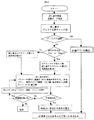
以上に説明した第1の実施例における好適な記録条件の検出方法を図2のフローチャートを用いて詳細に説明する。図2は、ディスク品質チェック用の第一の試し書きを行い、ディスク品質結果により第二の試し書きを行う処理を示したものである。ユーザが、ディスクをCD−Rドライブに装填した後に、ディスクにデータを書き込むことを選択した場合、第一の試し書き処理を行い、ディスク品質のチェックを行う。ディスクの品質があらかじめ定められた基準値を満たす場合は、好適なレーザパワーの算出等を行う。 A suitable recording condition detection method in the first embodiment described above will be described in detail with reference to the flowchart of FIG. FIG. 2 shows a process of performing the first test writing for checking the disc quality and performing the second test writing based on the disc quality result. When the user selects to write data to the disc after loading the disc into the CD-R drive, the first trial writing process is performed to check the disc quality. When the disc quality satisfies a predetermined reference value, a suitable laser power is calculated.
一方、ディスクの品質があらかじめ定められた基準値を満たさない場合は、第二の試し書き処理を行う。第二の試し書き処理により、レーザパワーの適正化だけでなく、発光タイミング調整、パルス幅、温度によって変化するレーザの発光パワーのズレ補正等、レーザドライバに与えるパラメータを増やし、好適なレーザ書き込みを実現する。あらかじめ、設定した許容値以内であったら、書き込み条件を算出する。許容値をはずれている場合は、ディスク上のゴミ、埃、傷等が原因と考えられるため、別エリアのPCAパーティションに移動し、再度試し書き処理を行う。この場合、試し書きの条件を変えて試し書きを行っても良いし、同じ条件で試し書きを行っても良い。設定した再処理回数を超えた場合は、異常と判断する。 On the other hand, if the disc quality does not satisfy a predetermined reference value, the second test writing process is performed. With the second trial writing process, not only optimization of laser power but also adjustment of emission timing, pulse width, correction of deviation of laser emission power that varies with temperature, etc., increased parameters to be given to the laser driver, suitable laser writing Realize. If it is within the set allowable value in advance, the write condition is calculated. If the tolerance is not met, it may be caused by dust, dust, scratches, etc. on the disk, so the PCA partition in another area is moved and the test writing process is performed again. In this case, the trial writing may be performed by changing the test writing conditions, or the test writing may be performed under the same conditions. When the set number of reprocessing is exceeded, it is determined as abnormal.
レーザドライバに与えるパラメータの取得方法としては、特殊パターンマークを記録し、再生ジッタの最も少ないパルスを決定する。または、ディスク上のPMA(ProgramMemoryArea)などに既に記録されている好適なパワーが、周囲温度等から大きくはずれていることも考えられるため、好適なパワーから考えられる上限値以上、下限値以下で特殊パターンを書き込み、その結果からレーザに与えるパラメータ適正値を求める。または、CD−Rでは、3Tピットから11Tピットまでの9種類の記録ピットが正確に形成される必要があるために、それぞれの波形について良好なピットが形成されるように、最良な記録ストラテジーを求める。または、記録パワーを変化させながらデータエッジとクロックエッジの位相ずれを検出し、等価的にジッタを測定して、好適な記録条件を求める。 As a method for acquiring parameters to be given to the laser driver, a special pattern mark is recorded and a pulse with the smallest reproduction jitter is determined. Or, it is possible that the suitable power already recorded in the PMA (ProgrammeMareaArea) etc. on the disc is greatly deviated from the ambient temperature, etc. A pattern is written, and an appropriate parameter value to be given to the laser is obtained from the result. Or, in the CD-R, since nine types of recording pits from 3T pits to 11T pits need to be accurately formed, the best recording strategy is set so that good pits are formed for each waveform. Ask. Alternatively, the phase shift between the data edge and the clock edge is detected while changing the recording power, and the jitter is measured equivalently to obtain a suitable recording condition.
上記のように、パラメータを増やすことになるとテスト領域を増やさなくてはならない。そのため、1回の試し書きでPCA領域の1パーティションだけでなく、複数パーティションを使用する。PCA領域は、100パーティションに分かれているため、1回の試し書きで2以上100以下のパーティションを使用できる。 As mentioned above, the test area must be increased when the parameters are increased. Therefore, not only one partition of the PCA area but also a plurality of partitions are used in one trial writing. Since the PCA area is divided into 100 partitions, 2 or more and 100 or less partitions can be used in one trial writing.
図3のフローチャートを用い、第2の実施例について説明する。本実施例の光ディスク装置の構成は図1のものと同様であるので説明は省略する。本実施例は、ディスクへの記録方法が、DiscatOnceであるか、それ以外の記録方法であるかにより第2の試し書きの方法を変更する点に特徴のある実施例である。 A second embodiment will be described using the flowchart of FIG. Since the configuration of the optical disk apparatus of the present embodiment is the same as that of FIG. 1, the description thereof is omitted. The present embodiment is an embodiment characterized in that the second test writing method is changed depending on whether the recording method on the disc is “DiscatOnce” or another recording method.
ここで、DiscatOnceは、ディスクに一度だけデータを書き込む記録方法であるため、PCA領域を全て使っても特に問題がない。一方、DiscatOnce以外の書き込み方法(TrackatOnce、SessionatOnce、PacketWrite等)は、追記する場合があるため、全てのパーティションを使用すると、追記時に試し書きができないという不具合が発生する。そのため、DiscatOnce以外の書き込み方法の場合は、一回の試し書きで使用するエリアの制限を行う必要があり、試し書きのパラメータ数、処理回数も少なくする。 Here, “DiscOnce” is a recording method in which data is written only once on the disc, so there is no particular problem even if the entire PCA area is used. On the other hand, since writing methods other than DisccOnce (TrackatOnce, SessionatOnce, PacketWrite, etc.) may be additionally written, if all partitions are used, there is a problem that trial writing cannot be performed at the time of additional writing. Therefore, in the case of a writing method other than DiscOnce, it is necessary to limit the area used in one trial writing, and the number of trial writing parameters and the number of processes are reduced.
試し書き処理の再処理回数、パラメータ数は、ホスト12から入力されたユーザのディスクへの書き込み指示が、Discatonceかどうかを書き込み方法判定部14にて判定する。ユーザが、ホスト12より、Discatonceを選択した場合は、書き込み方法判定部14により、Discatonceと判定され、再処理回数、パラメータ数を、最大、PCA領域のパーティション数まで設定することができる。Discatonce以外の方法である場合は、試し書き回数は、ディスクに追記する回数に依存する。TrackatOnce、SessionatOnce、PacketWrite等の書き込み方法毎に、再処理回数、パラメータ数を変更しても良い。
The number of rewriting processes and the number of parameters of the trial writing process are determined by the writing method determining unit 14 as to whether the user's instruction to write to the disk input from the
また、CD−Rディスクの場合、データ書き込み方法がDiscatOnceであり、かつ書き込みデータが1トラックの場合には、試し書き領域としてPMAを使用しても良い。CD−Rの場合、データ記録が完結するまでトラック情報が確定しないため、複数トラックがある場合は、リードインエリアにTOC(TableOfContents)を書き込むまでの間、トラック情報をPMAに一時的に記録しておくが、1トラック記録の場合は、PMAを使用することがないため、PMAを試し書きに利用しても不都合は生じない。 In the case of a CD-R disc, when the data writing method is “DiscOnce” and the writing data is one track, PMA may be used as the test writing area. In the case of a CD-R, track information is not determined until data recording is completed. If there are a plurality of tracks, the track information is temporarily recorded in the PMA until TOC (Table Of Contents) is written in the lead-in area. However, in the case of 1-track recording, since PMA is not used, there is no inconvenience even if PMA is used for test writing.
PMAを試し書きに使用する際の注意点として、PMAの外周は、データ領域に接しているため、この領域のアドレス情報であるATIP(AbsoluteTimeInPregroove)に影響がないように試し書きする必要がある。 As a point of caution when using PMA for test writing, the outer periphery of the PMA is in contact with the data area, so it is necessary to test-write so as not to affect the ATIP (AbsoluteTimeInPregroove) which is address information of this area.
図4のフローチャートを用い、第3の実施例について説明する。本実施例の光ディスク装置の構成は図1のものと同様であるので説明は省略する。本実施例は第2の試し書きに用いる時間を制限できる点に特徴のある実施例である。 A third embodiment will be described using the flowchart of FIG. Since the configuration of the optical disk apparatus of the present embodiment is the same as that of FIG. 1, the description thereof is omitted. This embodiment is an embodiment characterized in that the time used for the second test writing can be limited.
図4は、第一の試し書きの後に、ディスク品質が悪い場合はメッセージを出力し、ユーザが第二の試し書き時間を選択するものである。 In FIG. 4, after the first test writing, a message is output when the disc quality is poor, and the user selects the second test writing time.
ディスクの品質をチェックする第一の試し書きの後に、ディスクの品質が基準値を満たさない場合に、「ディスクの品質に不具合があるため、レーザ調整(試し書き)に時間がかかります。調整(試し書き)を行いますか?」等のメッセージをPCモニタ等に出力する。「レーザ調整(試し書き)を行う」を選択した場合は、その後に時間設定画面が出力され、ユーザがこれを選択する。ユーザにより設定された時間設定に応じて、試し書きのパラメータ数、再処理回数等を算出し、好適なレーザ書き込み条件を実現する。 After the first trial writing to check the disc quality, if the disc quality does not meet the standard value, “Because the disc quality is defective, the laser adjustment (trial writing) takes time. "Do you want to do trial writing?" Is output to a PC monitor or the like. When “perform laser adjustment (trial writing)” is selected, a time setting screen is output thereafter, and the user selects this. According to the time setting set by the user, the number of parameters for trial writing, the number of times of reprocessing, and the like are calculated to realize suitable laser writing conditions.
図5のフローチャートを用い、第4の実施例について説明する。本実施例の光ディスク装置の構成は図1のものと同様であるので説明は省略する。本実施例は内周側と外周側に試し書きエリアのあるディスクに本発明を適用した例である。 A fourth embodiment will be described using the flowchart of FIG. Since the configuration of the optical disk apparatus of the present embodiment is the same as that of FIG. 1, the description thereof is omitted. In this embodiment, the present invention is applied to a disc having test writing areas on the inner and outer peripheral sides.
上述したDVD+R/RWのように、内周側と外周側の両方に試し書きエリアがある場合には、InnerDriveAreaとOuterDriveAreaを試し書きに使用することができる。このようなディスクの場合は、ディスクの品質チェックを行う場合に、内周で試し書き処理を行った後に外周で試し書き処理を行い、内周と外周で異なる感度等を求めることにより、さらに詳細なパラメータをレーザドライバに与えることができる。 When there is a test writing area on both the inner and outer peripheral sides as in the DVD + R / RW described above, InnerDriveArea and OuterDriveArea can be used for test writing. In the case of such a disc, when performing a quality check on the disc, the test writing process is performed on the outer periphery after the test writing process is performed on the inner periphery, and different sensitivities, etc. are calculated on the inner periphery and the outer periphery. Parameters can be given to the laser driver.
DVD+R/RWは、CLV(ConstantLinearVelocity)及びCVA(ConstantAngularVelocity)記録が可能である。この場合、内周側のPCAにより設定したレーザービームの光量で線速度が大きく異なる外周側領域をアクセスすることになる。従ってこのような場合には、特にレーザービームの光量設定精度が低化しないように外周、内周側の両方で試し書きを行うようにする。この場合、InnerDriveAreaに設けられたインナーディスクテストゾーン、インナーディスクカウントゾーン、および、OuterDriveAreaに設けられたアウターディスクテストゾーン、アウターディスクカウントゾーンの全てを利用することが可能である。なお、DVD−R/RWディスクにおいても、PCA領域全部を使用することが可能である。 DVD + R / RW is capable of CLV (Constant Linear Velocity) and CVA (Constant Angular Velocity) recording. In this case, the outer peripheral side area where the linear velocity greatly differs depending on the light amount of the laser beam set by the inner peripheral PCA is accessed. Therefore, in such a case, trial writing is performed on both the outer and inner circumferences so that the light amount setting accuracy of the laser beam is not particularly lowered. In this case, it is possible to use all of the inner disk test zone and inner disk count zone provided in InnerDriveArea, and the outer disk test zone and outer disk count zone provided in OuterDriveArea. Note that it is possible to use the entire PCA area on a DVD-R / RW disc.
なお、図5の「内(外)周で試し書き処理1」「外(内)周で試し書き処理2」は、内周で試し書き1を行ったときは外周で試し書き2を行い、外周で試し書き1を行ったときは内周で試し書き2を行うことを示す。また、図5の「内(外)周で試し書き処理3」「外(内)周で試し書き処理4」は、内周で試し書き3を行ったときは外周で試し書き4を行い、外周で試し書き3を行ったときは内周で試し書き4を行うことを示す。
Note that “trial writing process 1 on the inner (outer) circumference” and “trial writing process 2 on the outer (inner) circumference” in FIG. 5 performs the test writing 2 on the outer circumference when the test writing 1 is performed on the inner circumference. When test writing 1 is performed on the outer periphery, it indicates that test writing 2 is performed on the inner periphery. Further, “
以上、本発明をCD−R、DVD+R/RWに記録する場合を例として説明したが、本発明は、その他の光ディスクに記録し、再生する任意の光記録再生装置において利用することが可能である。例えばDVD−RAMでは、リードイン領域、リードアウト領域に、DMA領域を有するが、DiscatOnceの場合は、この領域を使用した試し書きを行い、パラメータを増やし、さらに好適な値を求めることで、適切に書き込むようにする。 As described above, the present invention has been described as an example of recording on CD-R and DVD + R / RW. However, the present invention can be used in any optical recording / reproducing apparatus for recording and reproducing on other optical disks. . For example, a DVD-RAM has a DMA area in the lead-in area and the lead-out area, but in the case of DisccOnce, trial writing using this area is performed, the parameters are increased, and a more suitable value is obtained. To write to.
その他、ダウンロードサイトの情報をダウンロードし、直接光ディスクに書き込む場合も、上記処理を直接行うことにより、確実にディスクに書き込むことができる。重要なデータである場合に特に有効である。 In addition, when the information on the download site is downloaded and directly written to the optical disc, the above processing is directly performed so that the information can be reliably written to the disc. This is especially effective when the data is important.
1…光ディスク、2…スピンドルモータ、3…光ヘッド、4…再生回路、5…レーザ駆動回路、6…試し書き処理回路、7…復調回路、8…変調回路、9…制御回路、10…ディスク品質判定部、11…試し書きパラメータ制御部、12…ホストコンピュータ、13…メモリ、13…書き込み方法判定部。
DESCRIPTION OF SYMBOLS 1 ... Optical disk, 2 ... Spindle motor, 3 ... Optical head, 4 ... Reproduction circuit, 5 ... Laser drive circuit, 6 ... Trial writing processing circuit, 7 ... Demodulation circuit, 8 ... Modulation circuit, 9 ... Control circuit, 10 ... Disk Quality judging unit 11... Trial writing
Claims (5)
記録条件を定める機能を有し、
ディスク品質を確かめる第一の試し書き処理を行い、
ディスク品質がある一定の基準を満たさない場合に、
レーザパワー、発光タイミング調整、パルス幅の何れかの実行パラメータを増やし、第二の試し書き処理を行うことを特徴とする光ディスク記録装置。 An optical disc apparatus for recording and reproducing information on an optical information recording medium,
Has the function to define the recording conditions,
Perform the first trial writing process to check the disc quality,
If the disc quality does not meet certain criteria,
An optical disk recording apparatus characterized in that an execution parameter of any one of laser power, light emission timing adjustment, and pulse width is increased to perform a second test writing process.
前記第一の試し書き処理と前記第二の試し書き処理で、全てのパーティションまたは複数のパーティションを使用することを特徴とする光ディスク記録装置。 In claim 1, the test area partition of the test writing divided into a plurality provided in the optical information recording medium,
An optical disk recording apparatus, wherein all partitions or a plurality of partitions are used in the first test writing process and the second test writing process.
前記光学的情報記録媒体は、内周テストエリア領域と外周テストエリア領域を有する光学的情報記録媒体であり、
内周テストエリア領域、外周テストエリア領域の順番にて前記第一の試し書き処理と前記第二の試し書き処理を実行する、
または外周テストエリア領域、内周テストエリア領域の順番にて前記第一の試し書き処理と前記第二の試し書き処理を実行することを特徴とする光ディスク記録装置。 In claim 1,
The optical information recording medium is an optical information recording medium having an inner periphery test area region and an outer periphery test area region,
Performing the first test writing process and the second test writing process in the order of the inner test area area and the outer test area area;
Alternatively, the optical disc recording apparatus is characterized in that the first test writing process and the second test writing process are executed in the order of the outer periphery test area area and the inner periphery test area area.
前記第二の試し書き処理の記録条件を定めるときに照射するレーザを駆動するためのパラメータの数を増やし、
光学的情報記録媒体に設けられた複数に分けられた試し書きのテストエリア領域を、前記第二の試し書き処理で、全てのパーティションまで使用可能とすることを特徴とする光ディスク記録装置。 In claim 1, by inputting information to be written only once to the disc,
Increase the number of parameters for driving the laser to irradiate when determining the recording conditions of the second test writing process,
An optical disk recording apparatus characterized in that a plurality of test writing test area areas provided on an optical information recording medium can be used up to all partitions in the second test writing process.
前記第一の試し書き処理の結果、ディスク品質がある一定の基準を満たさない場合に、警告を出力し、第二の試し書き処理を選択する選択手段と、
前記第二の試し書き処理を選択した場合に、前記第二の試し書き処理時間を選択する処理時間選択手段を有し、
該処理時間選択手段により、第二の試し書き処理の記録条件を定めるときに照射するレーザを駆動するためのパラメータの数を変更することを特徴とする光ディスク記録装置。 In claim 1,
As a result of the first test writing process, when the disc quality does not satisfy a certain standard, a selection unit that outputs a warning and selects the second test writing process;
When the second test writing process is selected, the processing time selecting means for selecting the second test writing process time,
An optical disk recording apparatus characterized in that the processing time selection means changes the number of parameters for driving a laser to be irradiated when the recording condition of the second trial writing process is determined.
Priority Applications (1)
| Application Number | Priority Date | Filing Date | Title |
|---|---|---|---|
| JP2007024978A JP2007149337A (en) | 2007-02-05 | 2007-02-05 | Optical disk recording device |
Applications Claiming Priority (1)
| Application Number | Priority Date | Filing Date | Title |
|---|---|---|---|
| JP2007024978A JP2007149337A (en) | 2007-02-05 | 2007-02-05 | Optical disk recording device |
Related Parent Applications (1)
| Application Number | Title | Priority Date | Filing Date |
|---|---|---|---|
| JP2002334479A Division JP3931137B2 (en) | 2002-11-19 | 2002-11-19 | Optical disc recording apparatus and recording condition determining method |
Publications (1)
| Publication Number | Publication Date |
|---|---|
| JP2007149337A true JP2007149337A (en) | 2007-06-14 |
Family
ID=38210526
Family Applications (1)
| Application Number | Title | Priority Date | Filing Date |
|---|---|---|---|
| JP2007024978A Pending JP2007149337A (en) | 2007-02-05 | 2007-02-05 | Optical disk recording device |
Country Status (1)
| Country | Link |
|---|---|
| JP (1) | JP2007149337A (en) |
-
2007
- 2007-02-05 JP JP2007024978A patent/JP2007149337A/en active Pending
Similar Documents
| Publication | Publication Date | Title |
|---|---|---|
| JP2001331940A (en) | Optical disk recording method, optical disk recorder and optical disk | |
| JP2005038466A (en) | Trial write processing control method and optical disk device | |
| JPWO2005088613A1 (en) | Information recording apparatus and method, and computer program | |
| US7053919B2 (en) | Optical disk apparatus of variable recording velocity with optimum power control | |
| JP2000251256A (en) | Recorder, laser power setting method | |
| JP2000251254A (en) | Recording method and recording apparatus | |
| JP4559428B2 (en) | Information recording apparatus, information recording method, and information recording program | |
| US7518964B2 (en) | Information record apparatus and method, and computer program product | |
| JP2004310906A (en) | Optical disk recording method and optical disk recording device | |
| JP2004110993A (en) | Method for selecting laser power, information recording medium and information recorder | |
| JP2007141438A (en) | Method of determining optimum write power of optical disk and optical disk driving apparatus | |
| JP2000251257A (en) | Recorder and laser power setting method | |
| JP3931137B2 (en) | Optical disc recording apparatus and recording condition determining method | |
| JP2009238266A (en) | Optical disk apparatus and optical disk recording and reproducing method | |
| JP2008159195A (en) | Optical disk drive and its recording power setting method | |
| JP2003331427A (en) | Optical information recording and reproducing device | |
| US7701828B2 (en) | Optical recording system and method | |
| JP2007149337A (en) | Optical disk recording device | |
| US20040257932A1 (en) | Optical disk recording method and optical disk recording system | |
| JPWO2004077418A1 (en) | Information recording apparatus and information recording method | |
| JP2007213711A (en) | Optical disk recording method and optical disk recording device | |
| US20080130438A1 (en) | Optical disk apparatus and control method therefor | |
| JP2005141851A (en) | Optical disk device, parameter determination method, program and storage medium | |
| JP4561699B2 (en) | Recording / playback device | |
| KR100682147B1 (en) | Recording method for optical recorder |
Legal Events
| Date | Code | Title | Description |
|---|---|---|---|
| A131 | Notification of reasons for refusal |
Free format text: JAPANESE INTERMEDIATE CODE: A131 Effective date: 20070626 |
|
| A02 | Decision of refusal |
Free format text: JAPANESE INTERMEDIATE CODE: A02 Effective date: 20071023 |