JP2007149331A - Information recording medium - Google Patents
Information recording medium Download PDFInfo
- Publication number
- JP2007149331A JP2007149331A JP2006341557A JP2006341557A JP2007149331A JP 2007149331 A JP2007149331 A JP 2007149331A JP 2006341557 A JP2006341557 A JP 2006341557A JP 2006341557 A JP2006341557 A JP 2006341557A JP 2007149331 A JP2007149331 A JP 2007149331A
- Authority
- JP
- Japan
- Prior art keywords
- recording
- information
- layer
- area
- recorded
- Prior art date
- Legal status (The legal status is an assumption and is not a legal conclusion. Google has not performed a legal analysis and makes no representation as to the accuracy of the status listed.)
- Pending
Links
Images


Abstract
Description
本発明は、例えばDVD等の情報記録媒体の技術分野に関する。 The present invention relates to the technical field of information recording media such as DVDs.
例えば、CD、DVD等の情報記録媒体では、同一基板上に複数の記録層が積層されてなる多層型又はデュアルレイヤ(2層)型の記録型又は再生専用型光ディスク等も開発されている。詳細には、例えば、2層記録型光ディスクに対して情報を記録する、DVDレコーダ等の情報記録装置では、レーザ光の照射側から見て最も手前側に位置する記録層(本願では適宜「L0層」と称する)に対して記録用のレーザ光を集光することで、L0層に対して情報を加熱などによる非可逆変化記録方式(例えば、DVD−Rを対象)や書換え可能方式(例えば、DVD−R/Wを対象)で記録し、L0層等を介して、レーザ光の照射側から見てL0層の奥側に位置する記録層(本願では適宜「L1層」と称する)に対して該レーザ光を集光することで、L1層に対して情報を加熱などによる非可逆変化記録方式や書換え可能方式で記録することになる。 For example, for information recording media such as CDs and DVDs, multi-layer or dual layer (two-layer) recording type or read-only type optical discs in which a plurality of recording layers are laminated on the same substrate have been developed. More specifically, for example, in an information recording apparatus such as a DVD recorder that records information on a two-layer recording type optical disc, the recording layer located closest to the laser light irradiation side (referred to as “L0” in this application). The recording laser beam is focused on a layer (referred to as “layer”), whereby information is recorded on the L0 layer by irreversible change recording by heating or the like (for example, for DVD-R) or rewritable methods (for example, , DVD-R / W) and recorded on a recording layer (referred to as “L1 layer” in this application as appropriate) positioned on the far side of the L0 layer as viewed from the laser beam irradiation side via the L0 layer. On the other hand, by condensing the laser beam, information is recorded on the L1 layer by an irreversible change recording method such as heating or a rewritable method.
他方で、特許文献1等においては、DVD−R/RW等の記録型情報記録媒体に、該情報記録媒体に固有なメディアID等の識別情報、或いは、暗号化情報を予めプリ記録して販売し、ネットワークを介して暗号化されたDVDビデオコンテンツ(以下、適宜「暗号化コンテンツ」と称す)を配信する配信システムが開示されている。この暗号化は、例えば非特許文献4に記載の暗号化システムに準拠して行われる。この配信システムにおいては、従来のDVD−R/RW等の記録型情報記録媒体と同一の物理構造の情報記録媒体が利用される。
On the other hand, in
また、例えば、2層型DVD−ROM等の2層再生専用型情報記録媒体においては、該情報記録媒体に固有な識別情報や、該情報記録媒体上に予め記録されているアプリケーションソフトウェアの製造識別番号(シリアル番号)等の識別情報が、ユーザデータエリア等のデータエリアにおける記録方式と異なる記録方式で予めプリ記録されている。より詳細には、例えば、YAGレーザ等の高出力なレーザ光が、2つの記録層を貫くようにして照射されて、即ち、L0層の記録層、L0層の反射層、及び、L1層の記録層を焼き切るように照射されて、識別情報がバーコード状にBCA(Barcode Cutting Area)に予めプリ記録されている。 In addition, for example, in a dual-layer read-only information recording medium such as a dual-layer DVD-ROM, identification information unique to the information recording medium and manufacturing identification of application software recorded in advance on the information recording medium Identification information such as a number (serial number) is pre-recorded in advance by a recording method different from the recording method in the data area such as the user data area. More specifically, for example, a high-power laser beam such as a YAG laser is irradiated through the two recording layers, that is, the recording layer of the L0 layer, the reflective layer of the L0 layer, and the L1 layer. Irradiation is performed so as to burn out the recording layer, and the identification information is pre-recorded in advance in a barcode cutting area (BCA).
しかしながら、例えば、2層型DVD−R/RW等の多層記録型情報記録媒体の場合に、従来の2層型DVD−ROMのように、例えば、YAGレーザ等の高出力なレーザ光が各記録層を貫くような記録方式で、識別情報をNBCA(Narrow Barcode Cutting Area)に予めプリ記録すると、各記録層全体の色素膜の物理特性が劣化してしまい、記録型情報記録媒体としての信頼性が著しく低下してしまうという技術的な問題点がある。 However, for example, in the case of a multilayer recording type information recording medium such as a two-layer DVD-R / RW, a high-power laser beam such as a YAG laser is recorded on each recording medium, as in the case of a conventional two-layer DVD-ROM. If the identification information is pre-recorded in NBCA (Narrow Barcode Cutting Area) in a recording method that penetrates the layers, the physical properties of the dye film of each recording layer deteriorate, and the reliability as a recording type information recording medium There is a technical problem that the remarkably decreases.
また、多層記録型情報記録媒体の場合、全ての記録層に、各記録層に特有な記録制御情報が記録されることが望ましいが、上述した識別情報は1つの情報記録媒体に固有な情報を示すものであり、全ての記録層に予めプリ記録された場合、データ容量を無駄に消費してしまい、記録領域を有効に活用することができないという技術的な問題点もある。また、多層再生専用型情報記録媒体においても、仮に、一つの記録層に識別情報が、高出力なレーザ光によって、プリ記録された場合、対向する他の記録層における記録領域を有効に活用することができなかったという技術的な問題点がある。 In addition, in the case of a multilayer recording type information recording medium, it is desirable that recording control information unique to each recording layer is recorded on all recording layers. However, the identification information described above is information unique to one information recording medium. For example, when pre-recorded on all recording layers, the data capacity is wasted, and there is a technical problem that the recording area cannot be used effectively. In addition, even in a multi-layer read-only information recording medium, if identification information is pre-recorded on one recording layer with a high-power laser beam, the recording areas in the other recording layers facing each other are effectively used. There is a technical problem that could not be done.
本発明は、例えば上述した従来の問題点に鑑みなされたものであり、例えば、多層型情報記録媒体において、記録領域を有効に活用しつつ識別情報をプリ記録することが可能となる情報記録媒体を提供することを課題とする。 The present invention has been made in view of, for example, the above-described conventional problems. For example, in a multilayer information recording medium, an information recording medium capable of pre-recording identification information while effectively using a recording area. It is an issue to provide.
本発明の請求項1に記載の情報記録媒体は上記課題を解決するために、複数の記録情報を夫々記録するための複数の記録層を備えており、前記複数の記録層のうち、レーザ光が照射される側から見て一番手前側に位置する第1記録層(例えば、L0層)は、情報記録媒体を識別するための識別情報が予めプリ記録された識別情報記録領域(例えば、NBCA)を有する。
In order to solve the above problems, an information recording medium according to
本発明の作用及び利得は次に説明する実施の形態から明らかにされる。 The effect | action and gain of this invention are clarified from embodiment described below.
(情報記録媒体に係る実施形態)
本発明の情報記録媒体に係る実施形態は、複数の記録情報を夫々記録するための複数の記録層を備えており、前記複数の記録層のうち、レーザ光が照射される側から見て一番手前側に位置する第1記録層(例えば、L0層)は、情報記録媒体を識別するための識別情報が予めプリ記録された識別情報記録領域(例えば、NBCA)を有する。
(Embodiment related to information recording medium)
Embodiments according to the information recording medium of the present invention include a plurality of recording layers for recording a plurality of recording information, and one of the plurality of recording layers is viewed from the side irradiated with laser light. The first recording layer (for example, L0 layer) located on the front side of the count has an identification information recording area (for example, NBCA) in which identification information for identifying the information recording medium is pre-recorded.
本発明の情報記録媒体に係る実施形態によれば、例えば、ディスク状の基板の一方の面上に、第1記録層、並びに、少なくとも一つの他の記録層が積層されており、当該情報記録媒体は、2層型或いは多層型の例えばDVD或いは光ディスク等である。第1記録層には、例えば音声、映像情報或いはコンテンツ情報等の記録情報が記録可能とされている。同様にして、少なくとも一つの他の記録層には、例えば音声、映像情報或いはコンテンツ情報等の記録情報が記録可能とされている。このように構成されているので、記録用又は再生用レーザ光は、例えば、基板、第1記録層、及び、少なくとも一つの他の記録層の順番に照射される。 According to the embodiment of the information recording medium of the present invention, for example, the first recording layer and at least one other recording layer are laminated on one surface of the disk-shaped substrate, and the information recording The medium is a two-layer type or a multi-layer type such as a DVD or an optical disc. In the first recording layer, for example, recording information such as audio, video information or content information can be recorded. Similarly, recording information such as audio, video information or content information can be recorded in at least one other recording layer. Since it is configured in this manner, the recording or reproducing laser light is irradiated in the order of the substrate, the first recording layer, and at least one other recording layer, for example.
本実施形態では、特に、レーザ光が照射される側から見て一番手前側に位置する例えば、L0層等の第1記録層は、メディアID等の識別情報が記録される、例えば、NBCA等の識別情報記録領域を有する。より詳細には、識別情報は、以下のようにして、識別情報記録領域に記録される。先ず、例えば、イニシャライザー等のプリ記録装置によって、通常記録時のレーザ光とは異なる記録型情報記録媒体を初期化するためのレーザ光が、例えば、数十トラックの範囲に楕円形状で照射される。このレーザ光の照射が変調されることによって、例えば、色素を少量だけ含む記録領域と、色素を多量に含む記録領域とが形成されることで、識別情報がバーコード情報として、識別情報記録領域に予めプリ記録される。尚、このプリ記録の際には、通常の記録動作であるトラッキングサーボは行われずに、位置センサのみに基づいて、ステッピングモーターの回転制御が行われる。 In the present embodiment, in particular, the first recording layer such as the L0 layer, which is located on the foremost side when viewed from the side irradiated with the laser beam, records identification information such as a media ID, such as NBCA. Identification information recording area. More specifically, the identification information is recorded in the identification information recording area as follows. First, for example, a laser beam for initializing a recording type information recording medium different from the laser beam at the time of normal recording is irradiated in an elliptical shape within a range of several tens of tracks by a pre-recording device such as an initializer. The By modulating the laser light irradiation, for example, a recording area containing a small amount of dye and a recording area containing a large amount of dye are formed, so that the identification information becomes bar code information and the identification information recording area In advance. In this pre-recording, the tracking servo that is a normal recording operation is not performed, and the rotation control of the stepping motor is performed based only on the position sensor.
その結果、例えば、DVDプレーヤー等の情報記録再生装置が、例えば、シーク動作等の初期動作によって、識別情報を、他の制御情報の取得と同時に、又は、相前後して、迅速に取得することが可能となる。 As a result, for example, an information recording / reproducing apparatus such as a DVD player can quickly acquire the identification information simultaneously with or after the acquisition of other control information by an initial operation such as a seek operation. Is possible.
仮に、第1記録層以外の他の記録層が、識別情報記録領域を有した場合、情報記録再生装置が、例えば、ユーザデータエリア等の記録情報記録領域に記録されているユーザデータ等の記録情報へアクセスする際や、記録情報記録領域に記録されているアプリケーションプログラムを実行する際において、識別情報を取得するためには、現在アクセスしている記録層から、他の記録層へアクセスし、識別情報を取得しなければならない。このように情報記録再生装置による識別情報の取得動作は、初期動作とは別に行われるため、冗長的に時間が掛かってしまう。 If a recording layer other than the first recording layer has an identification information recording area, the information recording / reproducing apparatus records, for example, user data recorded in a recording information recording area such as a user data area. In order to obtain identification information when accessing information or when executing an application program recorded in the recording information recording area, the recording layer currently accessed is accessed from another recording layer, Identification information must be obtained. As described above, since the operation for acquiring the identification information by the information recording / reproducing apparatus is performed separately from the initial operation, it takes time redundantly.
これに対して、本実施形態によれば、例えば、多層記録型情報記録媒体において、識別情報が予めプリ記録された識別情報記録領域を、情報記録再生装置がより簡便且つ容易にアクセスすることが可能な記録層に配置させることによって、例えば、記録情報の再生のための設定時間を大幅に短縮化させることが可能となる。言い換えると、情報記録再生装置によって、情報記録媒体上の最小な範囲をサーチ(検索)することで、識別情報に加えて再生及び記録に関する制御情報の取得時間を短縮化することが可能となると共に、より多くの各種情報を取得することが可能となる。 In contrast, according to the present embodiment, for example, the information recording / reproducing apparatus can more easily and easily access the identification information recording area in which the identification information is pre-recorded in the multilayer recording type information recording medium. By disposing the recording layer in a possible recording layer, for example, it is possible to greatly shorten the set time for reproducing recorded information. In other words, by searching for the minimum range on the information recording medium by the information recording / reproducing apparatus, it becomes possible to shorten the acquisition time of control information related to reproduction and recording in addition to the identification information. More various information can be acquired.
また、第1記録層だけにおいて、識別情報がプリ記録された識別情報記録領域が配置されるので、対向する他の記録層の記録領域を有効に活用することが可能となる。 In addition, since the identification information recording area in which the identification information is pre-recorded is arranged only in the first recording layer, it is possible to effectively utilize the recording areas of the other opposing recording layers.
更に、また、L0層等の第1記録層に、識別情報記録領域を配置させることで、既存のDVDプレーヤー等の情報記録再生装置における初期動作における記録層のアクセス順序と一致させ互換性を保持させることも可能となる。 Furthermore, the identification information recording area is arranged in the first recording layer such as the L0 layer, so that the recording layer access order in the initial operation in the information recording / reproducing apparatus such as an existing DVD player is made compatible and the compatibility is maintained. It is also possible to make it.
本発明の情報記録媒体に係る実施形態の一態様では、前記識別情報は、当該情報記録媒体に固有の情報である。 In one aspect of the embodiment of the information recording medium of the present invention, the identification information is information unique to the information recording medium.
この態様によれば、識別情報に加えて、例えば、後述される暗号化情報に基づいて、当該情報記録媒体を唯一のユニークな情報記録媒体として特定することが可能となる。 According to this aspect, in addition to the identification information, for example, the information recording medium can be specified as the only unique information recording medium based on encrypted information described later.
その結果、配信システムにおいて、当該情報記録媒体に記録可能なコンテンツ等の記録情報の著作権保護を実現可能である。 As a result, it is possible to realize copyright protection of recorded information such as content that can be recorded on the information recording medium in the distribution system.
本発明の情報記録媒体に係る実施形態の他の態様では、前記複数の記録層のうち前記第1記録層(L0層)又は少なくとも一つの他の記録層は、前記識別情報に対応しており、前記複数の記録情報の少なくとも一部を暗号化するための暗号化情報を記録するための暗号化情報記録領域を有する。 In another aspect of the embodiment of the information recording medium of the present invention, the first recording layer (L0 layer) or at least one other recording layer of the plurality of recording layers corresponds to the identification information. And an encrypted information recording area for recording encrypted information for encrypting at least a part of the plurality of recorded information.
この態様によれば、暗号化情報に加えて、識別情報に基づいて、当該情報記録媒体を唯一のユニークな情報記録媒体として特定することが可能となる。 According to this aspect, it is possible to specify the information recording medium as the only unique information recording medium based on the identification information in addition to the encrypted information.
その結果、配信システムにおいて、当該情報記録媒体に記録可能なコンテンツ等の複数の記録情報の著作権保護を実現可能である。 As a result, in the distribution system, it is possible to realize copyright protection for a plurality of pieces of recorded information such as content that can be recorded on the information recording medium.
本発明の情報記録媒体に係る実施形態の他の態様では、前記第1記録層(L0層)は、前記複数の記録情報の再生及び記録を制御するための制御情報を記録可能な制御情報記録領域(コントロールデータゾーン)を更に有する。 In another aspect of the embodiment of the information recording medium of the present invention, the first recording layer (L0 layer) can record control information for controlling the reproduction and recording of the plurality of recorded information. It further has a region (control data zone).
この態様によれば、例えば、L0層等の第1記録層は、再生及び記録を制御するための制御情報が記録される、例えば、コントロールデータゾーン等の制御情報記録領域を更に有する。 According to this aspect, for example, the first recording layer such as the L0 layer further includes a control information recording area such as a control data zone in which control information for controlling reproduction and recording is recorded.
その結果、例えば、DVDプレーヤー等の情報記録再生装置が、例えば、シーク動作等の初期動作によって、前述した識別情報を、制御情報の取得と同時に、又は、相前後して、より迅速に取得することが可能となる。 As a result, for example, an information recording / reproducing apparatus such as a DVD player acquires the above-described identification information more quickly at the same time as or after the acquisition of the control information, for example, by an initial operation such as a seek operation. It becomes possible.
言い換えると、例えば、多層記録型情報記録媒体において、識別情報が予めプリ記録された識別情報記録領域と制御情報記録領域とを同一の記録層に配置させることによって、情報記録再生装置がより簡便且つ容易にアクセスすることが可能となり、例えば、記録情報の再生のための設定時間を大幅に短縮化させることが可能となる。 In other words, for example, in a multi-layer recording type information recording medium, the information recording / reproducing apparatus can be more simply and easily arranged by arranging the identification information recording area in which the identification information is pre-recorded and the control information recording area in the same recording layer. It is possible to easily access, for example, it is possible to greatly shorten the set time for reproducing recorded information.
この制御情報記録領域に係る態様では、前記制御情報記録領域(コントロールデータゾーン)においては、前記識別情報記録領域(NBCA)が存在するか否かを示すフラグ情報を記録可能であるように構成してもよい。 In the aspect relating to the control information recording area, flag information indicating whether or not the identification information recording area (NBCA) exists can be recorded in the control information recording area (control data zone). May be.
このように構成すれば、例えば、DVDプレーヤー等の情報記録再生装置が、例えば、シーク動作等の初期動作によって、制御情報の取得と同時に、又は、相前後して、識別情報記録領域が存在するか否かを示すフラグ情報を取得することが可能となる。 According to this configuration, for example, an information recording / reproducing apparatus such as a DVD player has an identification information recording area at the same time as or after the acquisition of control information by an initial operation such as a seek operation. It is possible to acquire flag information indicating whether or not.
従って、前述した識別情報を、より効率的に、より迅速且つ的確に取得することが可能となる。 Therefore, the above-described identification information can be acquired more efficiently, more quickly and accurately.
本発明の情報記録媒体に係る実施形態の他の態様では、前記複数の記録層は、前記複数の記録情報を記録するための記録トラックとして、ランドトラック及びグルーブトラックが交互に形成されている記録情報記録領域を夫々有し、前記識別情報記録領域においては、前記グルーブトラックが前記グルーブトラックに沿った方向に、再生光学系の光学伝達特性(MTF)に基づいて再生不可能となる所定空間周波数以上の空間周波数(2NA/λ)によって分断されている。 In another aspect of the embodiment of the information recording medium of the present invention, the plurality of recording layers is a recording in which land tracks and groove tracks are alternately formed as recording tracks for recording the plurality of recording information. Each of the information recording areas has a predetermined spatial frequency at which the groove track cannot be reproduced in the direction along the groove track based on the optical transfer characteristic (MTF) of the reproduction optical system. It is divided by the above spatial frequency (2NA / λ).
この態様によれば、第1の特徴として、識別情報記録領域においては、グルーブトラックがグルーブトラックに沿った方向に、再生光学系の光学伝達特性(MTF:Modulation Transfer Function)に基づいて再生不可能となる所定空間周波数(本数/mm)以上の空間周波数によって分断されている。ここに、「所定空間周波数」とは、例えば、光ピックアップの対物レンズ等の再生光学系の開口率(NA:Numerical Aperture)、及び、レーザ光の波長に基づいて決定される。より詳細には、空間周波数が比較的に小さい場合、分断されている一単位のグルーブ(溝)の長さは比較的に大きくなり、光学伝達特性、即ち、再生レベルは、比較的に大きくなり、「1」に近づく。他方、空間周波数が「所定空間周波数」よりも大きい場合、分断されている一単位のグルーブの長さは比較的に小さくなり、光学伝達特性、即ち、再生レベルは、「0:ゼロ」となる。 According to this aspect, as a first feature, in the identification information recording area, the groove track cannot be reproduced in the direction along the groove track based on the optical transfer characteristic (MTF: Modulation Transfer Function) of the reproduction optical system. It is divided by a spatial frequency equal to or higher than a predetermined spatial frequency (number / mm). Here, the “predetermined spatial frequency” is determined based on, for example, the numerical aperture (NA) of a reproducing optical system such as an objective lens of an optical pickup and the wavelength of laser light. More specifically, when the spatial frequency is relatively small, the length of one united groove (groove) is relatively large, and the optical transfer characteristic, that is, the reproduction level is relatively large. , Approaches "1". On the other hand, when the spatial frequency is larger than the “predetermined spatial frequency”, the length of the divided unit groove is relatively small, and the optical transfer characteristic, that is, the reproduction level is “0: zero”. .
その結果、第1記録層の識別情報記録領域に、バーコード情報として、プリ記録されている識別情報から得られた再生RF信号に、この分断されているグルーブトラックから得られる変調信号が重畳されることは殆ど又は完全にないといえる。 As a result, the modulated signal obtained from the divided groove track is superimposed on the reproduction RF signal obtained from the pre-recorded identification information as barcode information in the identification information recording area of the first recording layer. It can be said that there is little or no.
更に、この態様では、第2の特徴として、グルーブトラックを分断する「所定空間周波数」を調整することで、識別情報の少なくとも一部を担持するバーコード情報が記録されていない識別情報記録領域の一部における光透過率が、グルーブトラックが、空間周波数によって分断されていないと共にバーコード情報が記録されていないと仮定した場合の光透過率と比べて、バーコード情報が記録されている識別情報記録領域の他部における光透過率に近付けるように構成してもよい。加えて、この光透過率は、等しい程、より好ましい。ここに「等しく」とは、完全に等しいことの他、例えば、他の記録層に記録されている記録情報の再生を行なう際に、同一視できる程度に等しい光透過率である意味を含む。 Furthermore, in this aspect, as a second feature, by adjusting a “predetermined spatial frequency” for dividing the groove track, an identification information recording area in which barcode information carrying at least a part of the identification information is not recorded. Identification information in which barcode information is recorded compared to the light transmittance in the case where it is assumed that the light transmittance in part is not divided by the spatial frequency and the barcode information is not recorded. You may comprise so that the light transmittance in the other part of a recording area may be approximated. In addition, the light transmittance is more preferably equal. Here, “equal” includes, in addition to being completely equal, for example, meaning that the light transmittance is equal to the extent that it can be identified when reproducing recorded information recorded in another recording layer.
その結果、レーザ光が照射される側から見て第1記録層よりも奥側に位置する他の記録層にフォーカスが合わされた場合(合焦点した場合)、第1記録層にデフォーカスされて(ぼんやりと)照射されているレーザ光の光透過率を、第1記録層の識別情報記録領域におけるバーコード情報が記録されている領域又は記録されていない領域に関係なく、全体において平均して、殆ど又は完全に一定とすることが可能となる。従って、第1記録層よりも奥側に位置する他の記録層の記録情報記録領域に、記録されている記録情報から得られた再生RF信号に、第1記録層の識別情報記録領域におけるバーコード情報として記録されている識別情報から得られる変調信号が重畳されることは殆ど又は完全にないといえる。 As a result, when the other recording layer located behind the first recording layer as viewed from the side irradiated with the laser beam is focused (when focused), the first recording layer is defocused. The light transmittance of the laser beam irradiated (bluntly) is averaged over the whole area regardless of the area where the barcode information is recorded or not recorded in the identification information recording area of the first recording layer. , Almost or completely constant. Accordingly, a bar in the identification information recording area of the first recording layer is added to the reproduction RF signal obtained from the recording information recorded in the recording information recording area of the other recording layer located behind the first recording layer. It can be said that the modulation signal obtained from the identification information recorded as code information is hardly or completely superimposed.
以上より、上述した第1及び第2の特徴によって、第1記録層の識別情報記録領域において、識別情報を適切且つ正確にプリ記録することが可能となる。加えて、他の記録層に記録されている記録情報の再生に対しても、何ら悪影響を与えないことが可能となる。従って、対向する少なくとも一つの他の記録層の記録領域を有効に活用することが可能となる。 As described above, the identification information can be pre-recorded appropriately and accurately in the identification information recording area of the first recording layer by the first and second features described above. In addition, it is possible to have no adverse effect on the reproduction of recorded information recorded on other recording layers. Therefore, it is possible to effectively utilize the recording area of at least one other recording layer facing each other.
この空間周波数に係る態様では、前記所定空間周波数は、前記再生光学系の開口率(NA:Numerical Aperture)、及び、レーザ光の波長に基づいて決定されるように構成してもよい。 In the aspect relating to the spatial frequency, the predetermined spatial frequency may be determined based on an aperture ratio (NA) of the reproducing optical system and a wavelength of the laser beam.
このように構成すれば、所定空間周波数「X」は、次の式(1)によって、算出されることが可能となる。 With this configuration, the predetermined spatial frequency “X” can be calculated by the following equation (1).
X = 2NA/λ …… (1)
但し、「NA」は、例えば、光ピックアップの対物レンズ等の再生光学系の開口率(NA:Numerical Aperture)であり、「λ」は、レーザ光の波長である。
X = 2NA / λ (1)
However, “NA” is, for example, the numerical aperture (NA) of a reproducing optical system such as an objective lens of an optical pickup, and “λ” is the wavelength of laser light.
その結果、より適切且つ正確に、所定空間周波数を算出することが可能となる。 As a result, the predetermined spatial frequency can be calculated more appropriately and accurately.
本実施形態のこのような作用及び他の利得は次に説明する実施例から更に明らかにされる。 Such an operation and other advantages of the present embodiment will be further clarified from examples described below.
以上説明したように、本発明の情報記録媒体に係る実施形態によれば、複数の記録層のうち、レーザ光が照射される側から見て一番手前側に位置する第1記録層(L0層)は、情報記録媒体を識別するための識別情報が予めプリ記録された識別情報記録領域(NBCA)を有するので、例えば、多層記録型情報記録媒体において、識別情報が予めプリ記録された識別情報記録領域を、情報記録再生装置がより簡便且つ容易にアクセスすることが可能な記録層に配置させることによって、例えば、記録情報の再生のための設定時間を大幅に短縮化させることが可能となる。 As described above, according to the embodiment of the information recording medium of the present invention, of the plurality of recording layers, the first recording layer (L0 layer) located on the foremost side when viewed from the side irradiated with the laser beam. ) Has an identification information recording area (NBCA) in which identification information for identifying an information recording medium is pre-recorded. For example, in a multi-layer recording type information recording medium, identification information in which identification information is pre-recorded By arranging the recording area in a recording layer that can be accessed more easily and easily by the information recording / reproducing apparatus, for example, it is possible to significantly shorten the set time for reproducing the recorded information. .
(情報記録媒体の第1実施例)
次に、図1から図6を参照して、本発明の情報記録媒体の第1実施例に係る光ディスクについて図面に基づいて詳細に説明する。尚、説明の便宜上、図1及び図2においては、レーザ光は、上側から下側へ向けて、照射されている。よって、L0層(第1記録層)は、上側に位置している。他方、図3から図5、並びに、図7から図10においては、レーザ光は、下側から上側へ向けて照射されている。よって、L0層(第1記録層)は、下側に位置している。
(First embodiment of information recording medium)
Next, an optical disc according to a first embodiment of the information recording medium of the present invention will be described in detail with reference to the drawings with reference to FIGS. For convenience of explanation, in FIGS. 1 and 2, the laser light is irradiated from the upper side to the lower side. Therefore, the L0 layer (first recording layer) is located on the upper side. On the other hand, in FIGS. 3 to 5 and FIGS. 7 to 10, the laser light is irradiated from the lower side to the upper side. Therefore, the L0 layer (first recording layer) is located on the lower side.
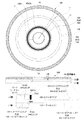
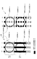
先ず、図1を参照して、本発明の情報記録媒体の第1実施例に係る光ディスクの基本構造について説明する。ここに、図1(a)は、本発明の情報記録媒体の第1実施例に係る複数の記録領域を有する光ディスクの基本構造を示した概略平面図であり、図1(b)は、該光ディスクの概略断面図と、これに対応付けられた、その半径方向における記録領域構造の図式的概念図である。尚、第1実施例に係る情報記録媒体は、有機色素膜を使用した追記型光ディスクからなる。尚、後述されるように、本実施例に係る情報記録媒体は、各種の加熱などによる可逆変化記録方式により多数回に亘って記録が可能であると共に多数回に亘って再生が可能である書換型光ディスクでもよい。 First, the basic structure of an optical disc according to the first embodiment of the information recording medium of the present invention will be described with reference to FIG. FIG. 1A is a schematic plan view showing the basic structure of an optical disc having a plurality of recording areas according to the first embodiment of the information recording medium of the present invention, and FIG. FIG. 2 is a schematic cross-sectional view of an optical disc and a schematic conceptual diagram of a recording area structure in the radial direction associated therewith. The information recording medium according to the first example is a write-once optical disc using an organic dye film. As will be described later, the information recording medium according to the present embodiment can be rewritten by a reversible change recording method using various heating and the like and can be reproduced many times. Type optical disk may be used.
特に、本実施例に係る光ディスク100は、図1(b)に示されるように、例えば、透明基板106に、後述される本発明に係る第1記録層及び他の記録層の一例を構成するL0層及びL1層が積層された構造をしている。このような二層型の光ディスク100の記録再生時には、図1(b)中、上側から下側に向かって照射されるレーザ光LBの集光位置をいずれの記録層に合わせるかに応じて、L0層における記録再生が行なわれるか又はL1層における記録再生が行われる。
In particular, as shown in FIG. 1B, the
図1(a)及び図1(b)に示されるように、光ディスク100は、例えば、DVDと同じく直径12cm程度のディスク本体上の記録面に、センターホール1を中心として本実施例に係るリードインエリア101、データエリア102、並びに、緩衝用エリアとしてのリードアウトエリア103又はミドルエリア104が設けられている。特に、例えば、リードインエリア101には、OPC処理を行うOPCエリアPCA0又はPCA1が設けられている。そして、光ディスク100の例えば、透明基板106に、記録層等が積層されている。そして、この記録層の各記録領域には、例えば、センターホール1を中心にスパイラル状或いは同心円状に、例えば、グルーブトラック及びランドトラック等のトラック10が交互に設けられている。また、このトラック10上には、データがECCブロック11という単位で分割されて記録される。ECCブロック11は、記録情報がエラー訂正可能なプリフォーマットアドレスによるデータ管理単位である。
As shown in FIGS. 1 (a) and 1 (b), an
L0層のリードインエリア101−0には、内周側から外周側に向けて、OPCエリアPCA0、NBCA(Narrow Burst Cutting Area)、及び、コントロールデータゾーンCDZが設けられている。 The lead-in area 101-0 of the L0 layer is provided with an OPC area PCA0, an NBCA (Narrow Burst Cutting Area), and a control data zone CDZ from the inner peripheral side toward the outer peripheral side.
OPCエリアPCA0は、L0層に記録情報を記録する際の最適記録パワーを決定するための試し書き情報を試し書きするための領域である。詳細には、OPCエリアPCA0及び後述されるPCA1は、記録レーザパワーのキャリブレーション処理、所謂、OPC処理に用いられる領域である。より詳細には、OPCパターンの試し書きの完了後には、試し書きされたOPCパターンが再生され、再生されたOPCパターンのサンプリングが順次行われて、最適記録パワーが検出される。また、OPC処理により求めた最適記録パワーの値が例えば、後述されるレコーディングマネージメントエリアRMA等に記録されていてもよいし、情報記録装置側に設けられた後述されるメモリ等の記憶装置内に格納されてもよいし、或いは、記録動作の度にOPC処理が行われてもよい。 The OPC area PCA0 is an area for trial writing of trial writing information for determining the optimum recording power when recording information is recorded on the L0 layer. Specifically, the OPC area PCA0 and PCA1, which will be described later, are areas used for recording laser power calibration processing, so-called OPC processing. More specifically, after completion of the trial writing of the OPC pattern, the trial-written OPC pattern is reproduced, and the reproduced OPC pattern is sequentially sampled to detect the optimum recording power. Further, the optimum recording power value obtained by the OPC process may be recorded, for example, in a recording management area RMA described later, or in a storage device such as a memory described later provided on the information recording device side. It may be stored, or OPC processing may be performed for each recording operation.
コントロールデータゾーンCDZには、この光ディスク100に対する再生及び記録を制御するための制御情報に加えて、所定の暗号化システムに基づいたディスクキーや、ディスクキーセット等の暗号化情報Key1がプリ記録されている。尚、ディスクキーや、ディスクキーセット等の暗号化情報Key1によって、本願発明に係る「暗号化情報」の一具体例が構成されている。また、本願発明に係る「制御情報記録領域」の一具体例が、このコントロールデータゾーンCDZによって構成されている。
In the control data zone CDZ, in addition to control information for controlling reproduction and recording on the
NBCAには、光ディスク100の一枚一枚に固有な製造番号、所謂、メディアID等の本願発明に係る「識別情報」がバーコード情報としてレーザーカッティングによって記録されている。
In the NBCA, the “identification information” according to the present invention such as a serial number unique to each
他方、L1層のリードインエリア101−1には、内周側から外周側に向けて、OPCエリアPCA1、及び、本願発明に係る「記録制御情報記録領域」の一例を構成するレコーディングマネージメントエリアRMAが設けられている。 On the other hand, in the lead-in area 101-1 of the L1 layer, from the inner periphery side toward the outer periphery side, the OPC area PCA1 and the recording management area RMA that constitutes an example of the “recording control information recording area” according to the present invention. Is provided.
OPCエリアPCA1は、L1層に記録情報を記録する際の最適記録パワーを決定するための試し書き情報を試し書きするための領域である。 The OPC area PCA1 is an area for trial writing of trial writing information for determining the optimum recording power when recording information is recorded on the L1 layer.
レコーディングマネージメントエリアRMAには、OPCエリアPCA0、及び、PCA1における試し書きによって算出された最適記録パワーの値が所定順序に従って記録される。 In the recording management area RMA, the optimum recording power values calculated by trial writing in the OPC areas PCA0 and PCA1 are recorded in a predetermined order.
データエリア102−0及び102−1には、暗号化システムに基づいたタイトルキー等の暗号化情報Key2と、このタイトルキー等の暗号化情報Key2によって暗号化された暗号化コンテンツが記録される。より具体的には、タイトルキー等の暗号化情報Key2は、前述したディスクキーや、ディスクキーセット等の暗号化情報Key1によって暗号化されている。 In the data areas 102-0 and 102-1, encrypted information Key2 such as a title key based on the encryption system and encrypted content encrypted by the encrypted information Key2 such as the title key are recorded. More specifically, the encryption information Key2 such as the title key is encrypted by the encryption information Key1 such as the disk key or the disk key set described above.
尚、本発明は、このような三つのエリアを有する光ディスクには特に限定されない。例えば、リードインエリア101、リードアウトエリア103又はミドルエリア104が存在せずとも、以下に説明するデータ構造等の構築は可能である。また、後述するように、リードインエリア101、リードアウト103又はミドルエリア104は更に細分化された構成であってもよい。
The present invention is not particularly limited to an optical disc having such three areas. For example, even if the lead-in
また、本実施例に係る光ディスク100は、2層片面、即ち、デュアルレイヤーシングルサイドに限定されるものではなく、2層両面、即ちデュアルレイヤーダブルサイドであってもよい。更に、上述の如く2層の記録層を有する光ディスクに限られることなく、3層以上の多層型の光ディスクであってもよい。
Further, the
尚、2層型光ディスクにおける記録再生手順は、例えば二つの記録層の間でトラックパスの方向が逆向きであるオポジット方式でもよいし、例えば二つの記録層の間でトラックパスの方向が同一であるパラレル方式でもよい。 The recording / reproducing procedure in the two-layer type optical disc may be an opposite method in which the direction of the track path is opposite between the two recording layers, for example, or the direction of the track path is the same between the two recording layers. A certain parallel system may be used.
次に図2を参照して、本発明の情報記録媒体の第1実施例に係る光ディスクの物理的構成の概略について説明する。より具体的には、第1実施例に係る光ディスク100では、複数のデータゾーン102等が例えば積層構造に形成される2層型の光ディスクとして構成されている。ここに、図2は、本発明の情報記録媒体の第1実施例に係る光ディスクの記録面における部分拡大斜視図である。
Next, with reference to FIG. 2, an outline of the physical configuration of the optical disc in the first embodiment of the information recording medium of the present invention will be described. More specifically, the
図2に示されるように、第1実施例では、光ディスク100は、ディスク状の透明基板106に面して下側に、情報記録面を構成する相変化型又は加熱などによる非可逆変化記録型(色素型)の第1記録層(L0層)107が積層され、更にその下側に、半透過反射膜108が積層されている。第1記録層107の表面からなる情報記録面には、グルーブトラックGT及びランドトラックLTが交互に形成されている。尚、光ディスク100の記録時及び再生時には、例えば図2に示したように、透明基板106を介してグルーブトラックGT上に、レーザ光LBが照射される。例えば、記録時には、記録レーザパワーでレーザ光LBが照射されることで、記録データに応じて、第1記録層107への相変化による書き込み又は加熱などによる非可逆変化記録が実施される。他方、再生時には、記録レーザパワーよりも弱い再生レーザパワーでレーザ光LBが照射されることで、第1記録層107へ書き込みされた記録データの読出しが実施される。
As shown in FIG. 2, in the first embodiment, the
第1実施例では、グルーブトラックGTは、一定の振幅及び空間周波数で揺動されていてもよい。即ち、グルーブトラックGTは、ウォブリングされており、そのウォブル109の周期は所定値に設定されている。ランドトラックLT上にはプリフォーマットアドレス情報を示すランドプリピットLPと呼ばれるアドレスピットが形成されている。この2つのアドレッシング(即ち、ウォブル109及びランドプリピットLP)により記録中のディスク回転制御や記録クロックの生成、また記録アドレス等のデータ記録に必要な情報を得ることができる。尚、グルーブトラックGTのウォブル109を周波数変調や位相変調など所定の変調方式により変調することによりプリフォーマットアドレス情報を予め記録するようにしてもよい。
In the first embodiment, the groove track GT may be oscillated with a constant amplitude and spatial frequency. That is, the groove track GT is wobbled, and the period of the
第1実施例では特に、半透過反射膜108に面して下側に、第2記録層(L1層)207が形成され、更にその下側に、反射膜208が形成されている。第2記録層207は、透明基板106、第1記録層107及び半透過反射膜108を介してレーザ光LBが照射されることで、第1記録層107と概ね同様に、相変化型又は加熱などによる非可逆変化記録型(色素型)の記録及び再生が可能なように構成されている。このような第2記録層207及び反射膜208については、第1記録層107及び半透過反射膜108等が形成された透明基板106上に積層、即ち、成膜形成してもよいし、別基板上に積層、即ち、成膜形成した後に、これを透明基板106に貼り合わせるようにしてもよい。尚、半透過反射膜108と第2記録層207との間には、製造方法に応じて適宜、透明接着剤等からなる透明な中間層205が設けられる。
In the first embodiment, in particular, a second recording layer (L1 layer) 207 is formed on the lower side facing the
このような二層型の光ディスク100の記録再生時には、レーザ光LBの集光位置、即ち、フォーカスをいずれの記録層に合わせるかに応じて、第1記録層107における記録再生が行なわれるか又は第2記録層207における記録再生が行われる。
At the time of recording / reproduction of such a two-layer type
(NBCAを中心としたデータ構造、及び、識別情報等の再生原理)
次に、図3から図6を参照して、本発明の情報記録媒体の第1実施例に係る2層型光ディスクのL0層におけるNBCAを中心とした詳細なデータ構造、及び、L0層のNBCAにプリ記録されている識別情報、及び、NBCAの少なくとも一部に対向したL1層の記録領域に記録されている記録情報の再生原理について説明する。
(Data structure centered on NBCA and the principle of reproduction of identification information, etc.)
Next, with reference to FIGS. 3 to 6, a detailed data structure centered on the NBCA in the L0 layer of the two-layer type optical disc according to the first embodiment of the information recording medium of the present invention, and the NBCA of the L0 layer. The reproduction principle of the identification information pre-recorded in the recording information and the recording information recorded in the recording area of the L1 layer facing at least part of the NBCA will be described.
(NBCAを中心としたデータ構造)
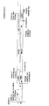
先ず、図3及び図4を参照して、本発明の情報記録媒体の第1実施例に係る2層型光ディスクのL0層におけるNBCAを中心とした詳細なデータ構造について、その作用効果の検討を含めて説明する。ここに、図3は、本発明の情報記録媒体の第1実施例に係る2層型光ディスクのL0層におけるNBCAを中心とした詳細なデータ構造の図式的断面図である。図4は、第1比較例に係る2層型光ディスクのL0層におけるNBCAを中心とした詳細なデータ構造の図式的断面図である。
(Data structure centered on NBCA)
First, with reference to FIG. 3 and FIG. 4, the effect of the detailed data structure centered on NBCA in the L0 layer of the two-layer type optical disc according to the first embodiment of the information recording medium of the present invention will be examined. Including. FIG. 3 is a schematic cross-sectional view of a detailed data structure centered on NBCA in the L0 layer of the two-layer type optical disc in the first embodiment of the information recording medium of the present invention. FIG. 4 is a schematic cross-sectional view of a detailed data structure centered on NBCA in the L0 layer of the two-layer type optical disc in the first comparative example.
図3に示されるように、光ディスク100は、2層の記録層、即ち、L0層(即ち、図1及び図2における第1記録層107に相当する記録層)とL1層(即ち、図1及び図2における第2記録層207に相当する記録層)とを有している。尚、説明の便宜上、記録用レーザ光LBは、図1及び図2とは逆に下側から上側へ向かって照射されている。
As shown in FIG. 3, the
L0層のリードインエリア101−0には、内周側から外周側に向かって、OPCエリアPCA0、NBCA、イニシャルゾーンINI、及び、コントロールデータゾーンCDZが設けられている。 In the lead-in area 101-0 of the L0 layer, OPC areas PCA0 and NBCA, an initial zone INI, and a control data zone CDZ are provided from the inner peripheral side toward the outer peripheral side.
詳細には、OPCエリアPCA0における、半径方向の位置は22.127976から22.58mmである。但し、試し書きは、この範囲において、外周側から内周側に向かって行われる。尚、本実施例の図3においては、オポジット方式におけるアドレスが表示されているが、パラレル方式を採用してもよい。 Specifically, the radial position in the OPC area PCA0 is 22.127976 to 22.58 mm. However, the trial writing is performed from the outer peripheral side toward the inner peripheral side in this range. In FIG. 3 of this embodiment, addresses in the opposite method are displayed, but a parallel method may be adopted.
NBCAにおける、半径方向の位置は22.58から23.57mmである。より詳細には、NBCAの開始地点の半径方向の位置は、22.71mmを中心として0.06mmだけ内周側又は外周側にズレてもよい。また、NBCAの終了地点の半径方向の位置は、23.51mmを中心として0.06mmだけ内周側又は外周側にズレてもよい。特に、本実施例においては、NBCAにおけるグルーブトラックは、所定空間周波数以上の空間周波数で分断されていてもよい。 In NBCA, the radial position is 22.58 to 23.57 mm. More specifically, the radial position of the NBCA start point may be shifted to the inner or outer peripheral side by 0.06 mm from the center of 22.71 mm. Further, the position in the radial direction of the end point of NBCA may be shifted to the inner peripheral side or the outer peripheral side by 0.06 mm around 23.51 mm. In particular, in the present embodiment, the groove track in the NBCA may be divided at a spatial frequency equal to or higher than a predetermined spatial frequency.
イニシャルゾーンINIは、半径方向の位置において23.57から23.785489mmの範囲で設けられてもよい。このイニシャルゾーンINIには、例えば、ゼロ等のダミーデータが記録される。 The initial zone INI may be provided in a range of 23.57 to 23.785489 mm in the radial position. For example, dummy data such as zero is recorded in the initial zone INI.
コントロールデータゾーンCDZは、半径方向の位置において23.785489から24.00mmの範囲で設けられてもよいし、セクタ番号において、002F200から002FE00の範囲で設けられてもよい。 The control data zone CDZ may be provided in the range of 23.785489 to 24.00 mm at the radial position, or may be provided in the range of 002F200 to 002FE00 in the sector number.
他方、L1層のリードインエリア101−1には、内周側から外周側に向かって、OPCエリアPCA1、及び、レコーディングマネージメントエリアRMAが設けられている。 On the other hand, in the lead-in area 101-1 of the L1 layer, an OPC area PCA1 and a recording management area RMA are provided from the inner peripheral side toward the outer peripheral side.
詳細には、OPCエリアPCA1における、半径方向の位置はOPCエリアPCA0と同様に、22.127976から22.58mmである。但し、試し書きは、この範囲において、内周側から外周側に向かって行われる。 More specifically, the position in the radial direction in the OPC area PCA1 is 22.127976 to 22.58 mm, similar to the OPC area PCA0. However, the test writing is performed from the inner circumference side toward the outer circumference side in this range.
レコーディングマネージメントエリアRMAは、L0層のNBCAの少なくとも一部に対向した記録領域に設けられている。レコーディングマネージメントエリアRMAの最内周端の半径方向の位置は、NBCAの最内周端の半径方向の位置よりも、例えば、0.2mm等の偏心量だけ外周側にズレている。他方、レコーディングマネージメントエリアRMAの最外周端の半径方向の位置も、NBCAの最外周端の半径方向の位置よりも、例えば、0.2mm等の偏心量だけ内周側にズレている。 The recording management area RMA is provided in a recording area facing at least a part of the NBCA in the L0 layer. The radial position of the innermost peripheral edge of the recording management area RMA is shifted to the outer peripheral side by an eccentric amount of 0.2 mm, for example, from the radial position of the innermost peripheral edge of NBCA. On the other hand, the radial position of the outermost peripheral end of the recording management area RMA is also shifted to the inner peripheral side by an eccentric amount of 0.2 mm, for example, from the radial position of the outermost peripheral end of NBCA.
以上のように、NBCAが、コントロールデータゾーンCDZと同様にして、L0層に設けられていることによって、例えば、DVDプレーヤー等の情報記録再生装置が、例えば、シーク動作等の初期動作によって、NBCAにプリ記録されている識別情報を、コントロールデータゾーンCDZに記録されている他の制御情報の取得と同時に、又は、相前後して、迅速に取得することが可能となる。 As described above, since the NBCA is provided in the L0 layer in the same manner as the control data zone CDZ, for example, an information recording / reproducing apparatus such as a DVD player can perform NBCA by an initial operation such as a seek operation. It is possible to quickly acquire the identification information pre-recorded on the recording medium simultaneously with or before the acquisition of other control information recorded in the control data zone CDZ.
仮に、L0層以外の他の記録層が、NBCAを有した場合、情報記録再生装置が、例えば、データエリアに記録されているユーザデータ等の記録情報へアクセスする際や、データエリアに記録されているアプリケーションプログラムを実行する際において、識別情報を取得するためには、現在アクセスしている記録層から、他の記録層へアクセスし、識別情報を取得しなければならない。このように情報記録再生装置による識別情報の取得動作は、初期動作とは別に行われるため、冗長的に時間が掛かってしまう。 If the recording layer other than the L0 layer has the NBCA, the information recording / reproducing apparatus records information in the data area, for example, when accessing recording information such as user data recorded in the data area. In order to acquire the identification information when executing the application program, it is necessary to access the other recording layer from the currently accessed recording layer and acquire the identification information. As described above, since the operation for acquiring the identification information by the information recording / reproducing apparatus is performed separately from the initial operation, it takes time redundantly.
これに対して、本実施例によれば、例えば、2層型光ディスクにおいて、識別情報が予めプリ記録されたNBCAを、情報記録再生装置がより簡便且つ容易にアクセスすることが可能なL0層に配置させることによって、例えば、記録情報の再生のための設定時間を大幅に短縮化させることが可能となる。言い換えると、情報記録再生装置によって、光ディスク上の最小な範囲をサーチ(検索)することで、識別情報に加えて再生及び記録に関する制御情報の取得時間を短縮化することが可能となると共に、より多くの各種情報を取得することが可能となる。 On the other hand, according to the present embodiment, for example, in a two-layer type optical disc, the NBCA in which the identification information is pre-recorded is changed to the L0 layer that can be accessed more easily and easily by the information recording / reproducing apparatus. By arranging, for example, it is possible to greatly shorten the set time for reproducing recorded information. In other words, by searching for the minimum range on the optical disc by the information recording / reproducing apparatus, it becomes possible to shorten the acquisition time of control information related to reproduction and recording in addition to the identification information, and more It becomes possible to acquire a lot of various information.
また、L0層だけにおいて、識別情報がプリ記録されたNBCAが配置されるので、対向するL1層の記録領域に、例えば、レコーディングマネージメントエリアRMAを配置して、有効に活用することが可能となる。 In addition, since the NBCA in which the identification information is pre-recorded is arranged only in the L0 layer, for example, the recording management area RMA can be arranged in the recording area of the facing L1 layer and can be used effectively. .
仮に、図4に示されるように、L0層のNBCAに、例えば、YAGレーザ等の高出力なレーザ光によって、識別情報をプリ記録した場合、L1層においてもレーザ光が貫通され、L1層の色素膜が非可逆変化をおこすため、他の記録情報を記録することは困難である。よって、L0層及びL1層における偏心量を考慮して、レコーディングマネージメントエリアRMAを2層に分散させて配置させなければならない。従って、データ容量を無駄に消費してしまい、記録領域を有効に活用することができなくなってしまう。 As shown in FIG. 4, when the identification information is pre-recorded on the NBCA in the L0 layer by, for example, a high-power laser beam such as a YAG laser, the laser beam is also penetrated in the L1 layer. Since the dye film causes an irreversible change, it is difficult to record other recording information. Therefore, the recording management area RMA must be distributed and arranged in two layers in consideration of the eccentricity in the L0 layer and the L1 layer. Therefore, the data capacity is wasted and the recording area cannot be used effectively.
これに対して、第1実施例によれば、L0層だけにおいて、識別情報がプリ記録されたNBCAが配置されるので、対向するL1層の記録領域に、例えば、レコーディングマネージメントエリアRMAを配置して、有効に活用することが可能となる。 On the other hand, according to the first embodiment, since the NBCA in which the identification information is pre-recorded is arranged only in the L0 layer, for example, the recording management area RMA is arranged in the recording area of the facing L1 layer. Thus, it can be used effectively.
更に、また、L0層等の第1記録層に、識別情報記録領域を配置させることで、既存のDVDプレーヤー等の情報記録再生装置における初期動作における記録層のアクセス順序と一致させ互換性を保持させることも可能となる。 Furthermore, the identification information recording area is arranged in the first recording layer such as the L0 layer, so that the recording layer access order in the initial operation in the information recording / reproducing apparatus such as an existing DVD player is made compatible and the compatibility is maintained. It is also possible to make it.
(識別情報等の再生原理)
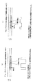
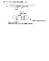
次に、図5から図9を参照して、本発明の情報記録媒体の第1実施例に係る2層型光ディスクのL0層のNBCAにプリ記録されている識別情報、及び、NBCAの少なくとも一部に対向したL1層の記録領域に記録されている記録情報の再生原理について説明する。ここに、図5は、本発明の情報記録媒体の第1実施例に係る2層型光ディスクのL0層のNBCAにプリ記録されている識別情報の再生原理を示した概念的断面図(図5(a))、及び、NBCAの少なくとも一部に対向したL1層の記録領域に記録されている記録情報の再生原理を示した概念的断面図(図5(b))である。図6は、本発明の情報記録媒体の第1実施例に係る2層型光ディスクのL0層のNBCAにおけるグルーブトラックを分断するための空間周波数と、光伝達特性(MTF:Modulation Transfer Function)との相関関係を示したグラフである。図7は、第2比較例に係る2層型光ディスクのL0層のNBCAにプリ記録されている識別情報の再生原理を示した概念的断面図である。図8は、本発明の情報記録媒体の第1実施例に係る2層型光ディスクのL0層のNBCAに識別情報がバーコード情報としてプリ記録されている領域と、プリ記録されていない領域とにおける光透過率を概念的に示した図式的上面図である。尚、図8において、右側部分は、グルーブトラックが、所定空間周波数以上の空間周波数によって、分断されているNBCAを示しており、左側部分は、グルーブトラックが、分断されていない記録領域を示している。
(Reproduction principle of identification information, etc.)
Next, with reference to FIG. 5 to FIG. 9, at least one of the identification information pre-recorded on the NBCA of the L0 layer of the two-layer optical disk according to the first embodiment of the information recording medium of the present invention and at least one of the NBCAs. The reproduction principle of the recorded information recorded in the recording area of the L1 layer facing the part will be described. FIG. 5 is a conceptual cross-sectional view showing the principle of reproducing the identification information pre-recorded on the NBCA of the L0 layer of the two-layer type optical disc according to the first embodiment of the information recording medium of the present invention (FIG. 5). FIG. 5A is a conceptual cross-sectional view (FIG. 5B) showing the reproduction principle of recorded information recorded in the recording area of the L1 layer facing at least a part of NBCA. FIG. 6 shows the relationship between the spatial frequency for dividing the groove track in the NBCA of the L0 layer of the two-layered optical disk according to the first embodiment of the information recording medium of the present invention, and the optical transfer characteristic (MTF: Modulation Transfer Function). It is the graph which showed correlation. FIG. 7 is a conceptual cross-sectional view showing the principle of reproducing identification information pre-recorded on the NBCA of the L0 layer of the two-layer type optical disc according to the second comparative example. FIG. 8 shows an area in which the identification information is pre-recorded as barcode information in the NBCA of the L0 layer of the two-layer type optical disc according to the first embodiment of the information recording medium of the present invention, and an area in which the pre-record is not performed. It is the schematic top view which showed light transmittance notionally. In FIG. 8, the right part shows the NBCA where the groove track is divided by a spatial frequency equal to or higher than a predetermined spatial frequency, and the left part shows a recording area where the groove track is not divided. Yes.
(識別情報等の再生原理の第1の特徴)
先ず、図5から図8を参照して、第1実施例に係るL0層のおける識別情報、及び、L1層における記録情報の再生原理の第1の特徴について、その作用効果の検討を加えて説明する。
(First feature of the principle of reproducing identification information, etc.)
First, with reference to FIG. 5 to FIG. 8, the effects of the identification information in the L0 layer according to the first embodiment and the first feature of the reproduction principle of the recorded information in the L1 layer are examined. explain.
図5及び後述される図8に示されるように、特に、本発明の情報記録媒体の第1実施例に係る2層型光ディスクでは、例えば製造時において、L0層のNBCAにおいては、グルーブトラックがグルーブトラックに沿った方向に、例えば、光ピックアップの対物レンズ等の再生光学系の光学伝達特性(MTF:Modulation Transfer Function)に基づいて再生不可能となる所定空間周波数以上の空間周波数(本数/mm)によって分断されている。ここに、「所定空間周波数」とは、例えば、光ピックアップの対物レンズ等の再生光学系の開口率(NA:Numerical Aperture)、及び、レーザ光の波長に基づいて決定される。詳細には、この所定空間周波数「X」は、次の式(1)によって、算出される。 As shown in FIG. 5 and FIG. 8 to be described later, in particular, in the two-layer type optical disc according to the first embodiment of the information recording medium of the present invention, for example, at the time of manufacture, the groove track is in the NBCA of the L0 layer. In the direction along the groove track, for example, a spatial frequency (number / mm) that is not less than a predetermined spatial frequency that cannot be reproduced based on an optical transfer characteristic (MTF: Modulation Transfer Function) of a reproduction optical system such as an objective lens of an optical pickup. ). Here, the “predetermined spatial frequency” is determined based on, for example, the numerical aperture (NA) of a reproducing optical system such as an objective lens of an optical pickup and the wavelength of laser light. Specifically, the predetermined spatial frequency “X” is calculated by the following equation (1).
X = 2NA/λ …… (1)
但し、「NA」は、例えば、光ピックアップの対物レンズ等の再生光学系の開口率(NA:Numerical Aperture)であり、「λ」は、レーザ光の波長である。
X = 2NA / λ (1)
However, “NA” is, for example, the numerical aperture (NA) of a reproducing optical system such as an objective lens of an optical pickup, and “λ” is the wavelength of laser light.
ここでは、
NA = 0.45
λ = 0.78(μm) であるので、
X = 1153.8462 (本数/mm) として算出される。
here,
NA = 0.45
Since λ = 0.78 (μm),
X = 1153.8462 (number / mm) is calculated.
より詳細には、図6のA点に示されるように、空間周波数が比較的に小さい場合、分断されている一単位のグルーブ(溝)の長さは比較的に大きくなり、光学伝達特性、即ち、再生レベルは、比較的に大きくなり、「1」に近づく。他方、図6のB点に示されるように、空間周波数が、約「1154」よりも大きい場合、分断されている一単位のグルーブの長さは比較的に小さくなり、光学伝達特性、即ち、再生レベルは、「0:ゼロ」となる。 More specifically, as shown by point A in FIG. 6, when the spatial frequency is relatively small, the length of one united groove (groove) is relatively large, and the optical transmission characteristics, That is, the reproduction level becomes relatively large and approaches “1”. On the other hand, as shown by point B in FIG. 6, when the spatial frequency is greater than about “1154”, the length of one united groove is relatively small, and the optical transfer characteristic, that is, The playback level is “0: zero”.
以上より、第1実施例に係るL0層のNBCAに、バーコード情報として、プリ記録されている識別情報から得られた再生RF信号に、この分断されているグルーブトラックから得られる変調信号が重畳されることは殆ど又は完全にないといえる。 As described above, the modulation signal obtained from the divided groove track is superimposed on the reproduction RF signal obtained from the pre-recorded identification information as the barcode information on the NBCA of the L0 layer according to the first embodiment. It can be said that little or no is done.
仮に、例えば、図6のC点に示されるように、L0層のNBCAにおいて、グルーブトラックがグルーブトラックに沿った方向に、所定空間周波数より小さい値である600(本数/mm)によって分断されている場合、光学伝達特性、即ち、再生レベルは、約「0.5」となり、図7に示されるように、L0層のNBCAに、バーコード情報として、プリ記録されている識別情報から得られた再生RF信号に、この分断されているグルーブトラックから得られる変調信号が重畳されてしまう。 For example, as shown at point C in FIG. 6, in the NBCA of the L0 layer, the groove track is divided in the direction along the groove track by 600 (number / mm) which is smaller than a predetermined spatial frequency. In this case, the optical transfer characteristic, that is, the reproduction level is about “0.5”, and is obtained from the pre-recorded identification information as barcode information in the NBCA of the L0 layer as shown in FIG. The modulated signal obtained from the divided groove track is superimposed on the reproduced RF signal.
これに対して、第1実施例に係るL0層のNBCAにおいては、グルーブトラックがグルーブトラックに沿った方向に、再生光学系の光学伝達特性(MTF)に基づいて再生不可能となる所定空間周波数以上の空間周波数によって分断されている。従って、L0層のNBCAに、バーコード情報として、プリ記録されている識別情報から得られた再生RF信号に、この分断されているグルーブトラックから得られる変調信号が重畳されることは殆ど又は完全にないといえる。 On the other hand, in the NBCA of the L0 layer according to the first embodiment, a predetermined spatial frequency at which the groove track cannot be reproduced in the direction along the groove track based on the optical transfer characteristic (MTF) of the reproduction optical system. It is divided by the above spatial frequency. Therefore, the modulation signal obtained from the divided groove track is hardly or completely superimposed on the reproduction RF signal obtained from the pre-recorded identification information as the barcode information on the NBCA of the L0 layer. It's not possible.
(識別情報等の再生原理の第2の特徴)
次に、図9に加えて前述した図5及び図8を適宜参照して、第1実施例に係るL0層のおける識別情報、及び、L1層における記録情報の再生原理の第2の特徴について、その作用効果の検討を加えて説明する。図9は、第3比較例に係る2層型光ディスクのL0層のNBCAにプリ記録されている識別情報の再生原理を示した概念的断面図(図9(a))、及び、NBCAの少なくとも一部に対向したL1層の記録領域に記録されている記録情報の再生原理を示した概念的断面図(図9(b))である。
(Second feature of the principle of reproducing identification information, etc.)
Next, referring to FIG. 5 and FIG. 8 as appropriate in addition to FIG. 9, the second feature of the identification information in the L0 layer and the recording information reproduction principle in the L1 layer according to the first embodiment is described. The explanation will be made with a study of the effects. FIG. 9 is a conceptual cross-sectional view (FIG. 9A) showing the reproduction principle of identification information pre-recorded on the NBCA of the L0 layer of the two-layer type optical disc in the third comparative example, and at least the NBCA FIG. 9B is a conceptual cross-sectional view (FIG. 9B) showing the principle of reproducing recorded information recorded in the recording area of the L1 layer facing part of it.
図8に示されるように、第1実施例では、グルーブトラックを分断する「所定空間周波数」を調整することで、NBCAの全体における色素の量を減少させ、識別情報を担持するバーコード情報が記録されていないNBCAの一部BA0における光透過率が、グルーブトラックが、空間周波数によって分断されていないと共にバーコード情報が記録されていないと仮定した領域BA0aの光透過率(比較的に小さい)と比べて、バーコード情報が記録されているNBCAの他部BA1における光透過率(比較的に大きい)に近付けるように構成してもよい。 As shown in FIG. 8, in the first embodiment, by adjusting the “predetermined spatial frequency” that divides the groove track, the amount of dye in the entire NBCA is reduced, and the barcode information that carries the identification information is changed. The light transmittance of the part BA0 of the NBCA that is not recorded is the light transmittance of the area BA0a (relatively small) on the assumption that the groove track is not divided by the spatial frequency and the barcode information is not recorded. Compared to the above, it may be configured to approach the light transmittance (relatively large) in the other part BA1 of the NBCA in which the barcode information is recorded.
その結果、前述した図5(b)に示されるように、レーザ光が照射される側から見てL0層よりも奥側に位置するL1層にフォーカスが合わされた場合(合焦点した場合)、L0層にデフォーカスされて(ぼんやりと)照射されているレーザ光の光透過率を、L0層のNBCAにおけるバーコード情報が記録されている領域又は記録されていない領域に関係なく、全体において平均して、殆ど又は完全に一定とすることが可能となる。 As a result, as shown in FIG. 5 (b) described above, when the L1 layer located behind the L0 layer as viewed from the laser beam irradiation side is focused (when focused), Average light transmittance of the laser beam defocused and irradiated on the L0 layer regardless of the area where the barcode information in the NBCA of the L0 layer is recorded or not recorded. Thus, it can be made almost or completely constant.
仮に、NBCAにおいて、グルーブトラックを分断しなかった場合、図8の左側部分、及び、図9(a)に示されるように、バーコード情報が記録されている領域、及び、記録されていない領域における光透過率を明確に異ならせることが可能となり、L0層のNBCAにプリ記録されている識別情報を再生した場合、良好な再生RF変調を得られるかもしれない。しかしながら、図9(b)に示されるように、L0層のNBCAよりも奥側に位置するL1層の記録領域に、記録されている記録情報から得られた再生RF信号においては、L0層のNBCAにおける光透過率の明確な違いが影響して、バーコード情報として記録されている識別情報から得られる変調信号が大きく影響してしまう。 If the groove track is not divided in the NBCA, as shown in the left part of FIG. 8 and the area shown in FIG. 9A, the area where the barcode information is recorded and the area where the track information is not recorded It is possible to clearly vary the light transmittance in the case of reproducing the identification information pre-recorded in the NBCA of the L0 layer, and a good reproduction RF modulation may be obtained. However, as shown in FIG. 9B, in the reproduction RF signal obtained from the recorded information recorded in the recording area of the L1 layer located behind the NBCA of the L0 layer, in the L0 layer, A clear difference in light transmittance in NBCA is affected, and a modulation signal obtained from identification information recorded as barcode information is greatly affected.
これに対して、第1実施例によれば、前述した図5(b)に示されるように、レーザ光が照射される側から見てL0層よりも奥側に位置するL1層にフォーカスが合わされた場合(合焦点した場合)、L0層にデフォーカスされて(ぼんやりと)照射されているレーザ光の光透過率を、L0層のNBCAにおけるバーコード情報が記録されている領域又は記録されていない領域に関係なく、全体において平均して、殆ど又は完全に一定とすることが可能となる。従って、L0層のNBCAよりも奥側に位置するL1層の記録領域に、記録されている記録情報から得られた再生RF信号に、L0層のNBCAにおけるバーコード情報として記録されている識別情報から得られる変調信号の影響を殆ど又は完全になくすことが可能となる。 On the other hand, according to the first embodiment, as shown in FIG. 5B described above, the focus is on the L1 layer located behind the L0 layer when viewed from the laser light irradiation side. When aligned (when focused), the light transmittance of the laser beam defocused (blurred) and irradiated on the L0 layer is recorded in the area where the barcode information in the NBCA of the L0 layer is recorded or recorded. Regardless of the area that is not, it can be almost or completely constant on average throughout. Therefore, the identification information recorded as the barcode information in the NBCA of the L0 layer in the reproduction RF signal obtained from the recorded information recorded in the recording area of the L1 layer located behind the NBCA of the L0 layer. It is possible to eliminate almost or completely the influence of the modulation signal obtained from (1).
以上より、上述した図5から図9を参照して説明したように、第1実施例に係るL0層のおける識別情報、及び、L1層における記録情報の再生原理の第1及び第2の特徴によって、L0層のNBCAにおいて、識別情報を適切且つ正確にプリ記録することが可能となる。加えて、L1層に記録されている記録情報の再生に対しても、何ら悪影響を与えないことが可能となる。従って、対向するL1層を含む他の記録層の記録領域を有効に活用することが可能となる。 As described above, as described with reference to FIGS. 5 to 9 described above, the first and second features of the identification information in the L0 layer and the reproduction principle of the recorded information in the L1 layer according to the first embodiment. Thus, it becomes possible to pre-record the identification information appropriately and accurately in the NBCA of the L0 layer. In addition, no adverse effect can be exerted on the reproduction of the recorded information recorded in the L1 layer. Therefore, it is possible to effectively utilize the recording areas of other recording layers including the facing L1 layer.
(情報記録媒体の第2実施例)
次に、図10を参照して、本発明の情報記録媒体の第2実施例に係る2層型光ディスクのL0層におけるNBCAを中心とした詳細なデータ構造について説明する。ここに、図10は、本発明の情報記録媒体の第2実施例に係る2層型光ディスクのL0層におけるNBCAを中心とした詳細なデータ構造の図式的断面図である。
(Second embodiment of information recording medium)
Next, with reference to FIG. 10, a detailed data structure centered on NBCA in the L0 layer of the two-layer type optical disc according to the second embodiment of the information recording medium of the present invention will be described. FIG. 10 is a schematic cross-sectional view of a detailed data structure centered on NBCA in the L0 layer of the two-layer type optical disc in the second embodiment of the information recording medium of the present invention.
図10に示されるように、第2実施例に係る光ディスク100のデータ構造は、前述した第1実施例に係る光ディスクと概ね同様である。
As shown in FIG. 10, the data structure of the
L0層のリードインエリア101−0には、内周側から外周側に向かって、OPCエリアPCA0、第1レコーディングマネージメントエリアRMA1、NBCA、イニシャルゾーンINI、及び、コントロールデータゾーンCDZが設けられている。 The lead-in area 101-0 of the L0 layer is provided with an OPC area PCA0, a first recording management area RMA1, NBCA, an initial zone INI, and a control data zone CDZ from the inner circumference side toward the outer circumference side. .
詳細には、OPCエリアPCA0における、半径方向の位置は22.127976から22.400282mm、セクタ番号は00203A0から0022710、LPPアドレスは、FFDFC5からFFDD8Eである。 Specifically, in the OPC area PCA0, the radial position is 22.127976 to 22.400282 mm, the sector number is 00203A0 to 0022710, and the LPP address is FFDFC5 to FFDD8E.
第1レコーディングマネージメントエリアRMA1における、半径方向の位置は22.400282から22.58mmである。 The radial position in the first recording management area RMA1 is 22.400282 to 22.58 mm.
NBCAの位置、アドレス、及び、グルーブトラックの分断については、第1実施例の場合と同様である。 The NBCA position, address, and groove track division are the same as in the first embodiment.
イニシャルゾーンINI、及び、コントロールデータゾーンCDZについても、第1実施例の場合と同様である。 The initial zone INI and the control data zone CDZ are the same as in the first embodiment.
他方、L1層のリードインエリア101−1には、内周側から外周側に向かって、OPCエリアPCA1、及び、第2レコーディングマネージメントエリアRMA2が設けられている。 On the other hand, in the lead-in area 101-1 of the L1 layer, an OPC area PCA1 and a second recording management area RMA2 are provided from the inner circumference side toward the outer circumference side.
詳細には、OPCエリアPCA1における、半径方向の位置はOPCエリアPCA0と同様に、22.127976から22.400282mmである。 Specifically, the radial position in the OPC area PCA1 is 22.127976 to 22.400282 mm, as in the OPC area PCA0.
第2レコーディングマネージメントエリアRMA2は、L0層の第1レコーディングマネージメントエリアRMA1に対向した記録領域に設けられている。 The second recording management area RMA2 is provided in a recording area facing the first recording management area RMA1 in the L0 layer.
第2レコーディングマネージメントエリアRMA2の最内周端の半径方向の位置は、第1レコーディングマネージメントエリアRMA1の最内周端の半径方向の位置よりも、例えば、0.2mm等の偏心量だけ外周側にズレている。他方、第2レコーディングマネージメントエリアRMA2の最外周端の半径方向の位置については、L0層の第1レコーディングマネージメントエリアRMA1の最外周端からの偏心量を考慮しなくてもよいばかりでなく、最大で、L0層のNBCAの最外周端の半径方向の位置よりも、例えば、0.2mm等の偏心量だけ内周側にズレた位置まで配置することが可能となる。 The radial position of the innermost peripheral edge of the second recording management area RMA2 is, for example, more eccentric than the radial position of the innermost peripheral edge of the first recording management area RMA1 by an eccentric amount such as 0.2 mm. There is a gap. On the other hand, regarding the radial position of the outermost peripheral edge of the second recording management area RMA2, not only the eccentricity from the outermost peripheral edge of the first recording management area RMA1 of the L0 layer need not be considered, Thus, it is possible to arrange the NBCA at a position shifted to the inner peripheral side by an eccentric amount of 0.2 mm or the like from the radial position of the outermost peripheral end of the NBCA of the L0 layer.
以上より、L0層だけにおいて、識別情報がプリ記録されたNBCAが配置されるので、対向するL1層の記録領域に、例えば、第2レコーディングマネージメントエリアRMA2や、データエリア等の記録領域を配置して、より有効に活用することが可能となる。 As described above, since the NBCA in which the identification information is pre-recorded is arranged only in the L0 layer, for example, the recording area such as the second recording management area RMA2 and the data area is arranged in the recording area of the facing L1 layer. Therefore, it can be used more effectively.
本実施例では、情報記録媒体の一具体例として、例えば、2層型DVD−R又はDVD−R/W等の追記型又は書き換え型光ディスクについて説明したが、本発明は、例えば、3層型や、4層型等のマルチプルレイヤ型の光ディスクにも適用可能である。更に、ブルーレイ(Blue-ray)ディスク等の大容量記録媒体にも適用可能である。 In this embodiment, as a specific example of the information recording medium, for example, a write-once type or rewritable optical disc such as a double-layer type DVD-R or DVD-R / W has been described. It can also be applied to a multiple layer type optical disc such as a four layer type. Furthermore, the present invention can be applied to a large-capacity recording medium such as a Blu-ray disc.
本発明は、上述した実施例に限られるものではなく、請求の範囲及び明細書全体から読み取れる発明の要旨或いは思想に反しない範囲で適宜変更可能であり、そのような変更を伴う情報記録媒体もまた本発明の技術的範囲に含まれるものである。 The present invention is not limited to the above-described embodiments, and can be appropriately changed without departing from the gist or concept of the invention that can be read from the claims and the entire specification. An information recording medium accompanying such a change is also applicable. Moreover, it is included in the technical scope of the present invention.
1…センターホール、10…トラック、11…セクタ、100…光ディスク、101−0(101−1)…リードインエリア、102−0(102−1)…データエリア、103−0(103−1)…リードアウトエリア、104−0(104−1)…ミドルエリア、106…透明基板、107…第1記録層、107a…色素膜、108…半透過反射膜、109…ウォブル、205…中間層、207…第2記録層、208…反射膜、GT…グルーブトラック、LT…ランドトラック、LB…レーザ光、LP…ランドプリピット、PCA0(PCA1)…OPCエリア、RMA(RMA1、RMA2)…レコーディングマネージメントエリア等、NBCA…Narrow Barcode Cutting Area、INI…イニシャルゾーン、CDZ…コントロールデータゾーン、Key1(Key2)…暗号化情報
DESCRIPTION OF
Claims (7)
前記複数の記録層のうち、レーザ光が照射される側から見て一番手前側に位置する第1記録層は、情報記録媒体を識別するための識別情報が予めプリ記録された識別情報記録領域を有することを特徴とする情報記録媒体。 A plurality of recording layers for recording a plurality of recording information respectively,
Among the plurality of recording layers, the first recording layer located on the foremost side when viewed from the side irradiated with the laser beam is an identification information recording area in which identification information for identifying the information recording medium is pre-recorded An information recording medium comprising:
前記識別情報記録領域においては、前記グルーブトラックが前記グルーブトラックに沿った方向に、再生光学系の光学伝達特性に基づいて再生不可能となる所定空間周波数以上の空間周波数によって分断されていることを特徴とする請求項1から5のいずれか一項に記載の情報記録媒体。 The plurality of recording layers each have a recording information recording area in which land tracks and groove tracks are alternately formed as recording tracks for recording the plurality of recording information,
In the identification information recording area, the groove track is divided in a direction along the groove track by a spatial frequency equal to or higher than a predetermined spatial frequency that cannot be reproduced based on the optical transmission characteristics of the reproduction optical system. The information recording medium according to any one of claims 1 to 5, characterized in that:
Priority Applications (1)
| Application Number | Priority Date | Filing Date | Title |
|---|---|---|---|
| JP2006341557A JP2007149331A (en) | 2004-07-05 | 2006-12-19 | Information recording medium |
Applications Claiming Priority (3)
| Application Number | Priority Date | Filing Date | Title |
|---|---|---|---|
| JP2004198522 | 2004-07-05 | ||
| JP2004198522 | 2004-07-05 | ||
| JP2006341557A JP2007149331A (en) | 2004-07-05 | 2006-12-19 | Information recording medium |
Related Parent Applications (1)
| Application Number | Title | Priority Date | Filing Date |
|---|---|---|---|
| JP2006528884A Division JP4439521B2 (en) | 2004-07-05 | 2005-07-04 | Information recording medium |
Publications (2)
| Publication Number | Publication Date |
|---|---|
| JP2007149331A true JP2007149331A (en) | 2007-06-14 |
| JP2007149331A6 JP2007149331A6 (en) | 2007-09-06 |
Family
ID=38210521
Family Applications (1)
| Application Number | Title | Priority Date | Filing Date |
|---|---|---|---|
| JP2006341557A Pending JP2007149331A (en) | 2004-07-05 | 2006-12-19 | Information recording medium |
Country Status (1)
| Country | Link |
|---|---|
| JP (1) | JP2007149331A (en) |
-
2006
- 2006-12-19 JP JP2006341557A patent/JP2007149331A/en active Pending
Similar Documents
| Publication | Publication Date | Title |
|---|---|---|
| JP3812584B1 (en) | Optical disc and optical disc apparatus | |
| JP2002352469A (en) | Multilayer information recording medium and information recording/reproducing device | |
| JP4439521B2 (en) | Information recording medium | |
| KR100832412B1 (en) | Information recording medium, information recording device and method, and computer program | |
| KR20040023128A (en) | Optical information storage medium | |
| JP4200335B2 (en) | Information recording medium, and information recording apparatus and method | |
| JPWO2006004087A1 (en) | Information recording medium | |
| JP2010186543A (en) | Method for reproducing optical information recording medium and method for recording optical information recording medium | |
| JPWO2006004089A1 (en) | Information recording medium | |
| JP2002133667A (en) | Medium, device and method for recording information and device, and method for reproducing information | |
| JP4315253B2 (en) | Information recording medium | |
| JP2007149331A (en) | Information recording medium | |
| JP2007149331A6 (en) | Information recording medium | |
| JP2009037705A (en) | Information recording medium, information recording and reproducing device, and information recording and reproducing method | |
| WO2007046492A1 (en) | Information recording medium, information recording device and method, information reproducing device and method, and information recording medium manufacturing device and method | |
| JP4475428B2 (en) | Information recording medium, information recording apparatus and method, and computer program | |
| KR100754229B1 (en) | Apparatus for reproducing data from optical information storage medium | |
| KR100739806B1 (en) | Apparatus for reproducing data from optical information storage medium | |
| JP4641189B2 (en) | Information playback device | |
| KR100765800B1 (en) | Optical information storage medium and method for reproducing data from the same | |
| US20090268593A1 (en) | Information recording medium, information recording apparatus and method, information reproducing apparatus and method, and computer program | |
| JP2005116177A (en) | Multilayer information recording medium and information reproducing device | |
| JP2004006050A (en) | Information recording medium | |
| JP2004014002A (en) | Information recording medium, optical disk device, and information recording method | |
| JP2008010117A (en) | Optical disk recording device and optical disk recording method |
Legal Events
| Date | Code | Title | Description |
|---|---|---|---|
| A977 | Report on retrieval |
Free format text: JAPANESE INTERMEDIATE CODE: A971007 Effective date: 20081222 |
|
| A131 | Notification of reasons for refusal |
Free format text: JAPANESE INTERMEDIATE CODE: A131 Effective date: 20090106 |
|
| A02 | Decision of refusal |
Free format text: JAPANESE INTERMEDIATE CODE: A02 Effective date: 20090630 |