JP2007149205A - Magnetic head device - Google Patents
Magnetic head device Download PDFInfo
- Publication number
- JP2007149205A JP2007149205A JP2005341521A JP2005341521A JP2007149205A JP 2007149205 A JP2007149205 A JP 2007149205A JP 2005341521 A JP2005341521 A JP 2005341521A JP 2005341521 A JP2005341521 A JP 2005341521A JP 2007149205 A JP2007149205 A JP 2007149205A
- Authority
- JP
- Japan
- Prior art keywords
- negative pressure
- positive pressure
- magnetic head
- slider
- pressure generating
- Prior art date
- Legal status (The legal status is an assumption and is not a legal conclusion. Google has not performed a legal analysis and makes no representation as to the accuracy of the status listed.)
- Pending
Links
Images


Classifications
-
- G—PHYSICS
- G11—INFORMATION STORAGE
- G11B—INFORMATION STORAGE BASED ON RELATIVE MOVEMENT BETWEEN RECORD CARRIER AND TRANSDUCER
- G11B5/00—Recording by magnetisation or demagnetisation of a record carrier; Reproducing by magnetic means; Record carriers therefor
- G11B5/48—Disposition or mounting of heads or head supports relative to record carriers ; arrangements of heads, e.g. for scanning the record carrier to increase the relative speed
- G11B5/58—Disposition or mounting of heads or head supports relative to record carriers ; arrangements of heads, e.g. for scanning the record carrier to increase the relative speed with provision for moving the head for the purpose of maintaining alignment of the head relative to the record carrier during transducing operation, e.g. to compensate for surface irregularities of the latter or for track following
- G11B5/60—Fluid-dynamic spacing of heads from record-carriers
- G11B5/6005—Specially adapted for spacing from a rotating disc using a fluid cushion
Abstract
Description
本発明は、ハードディスクなどの磁気記録媒体に対向するスライダに磁気機能部が設けられた磁気ヘッド装置に係り、特に、使用環境の空気密度が変化したときに、記録媒体からの浮上距離の変動を抑制できるようにした磁気ヘッド装置に関する。 The present invention relates to a magnetic head device in which a magnetic function unit is provided on a slider facing a magnetic recording medium such as a hard disk, and in particular, when the air density in a use environment changes, the flying distance from the recording medium varies. The present invention relates to a magnetic head device that can be suppressed.
ハードディスクなどの磁気記録媒体に磁気信号を記録し、また磁気記録媒体に記録された磁気信号を読み取る磁気ヘッド装置として、磁気記録媒体に対向するスライダを有し、このスライダのトレーリング側端部に磁気機能部が設けられたものが使用されている。磁気機能部は、MR効果やGMR効果を利用した再生機能部と、磁性材料のヨークおよびコイルなどが薄膜で形成された記録機能部とを有している。 As a magnetic head device for recording a magnetic signal on a magnetic recording medium such as a hard disk and reading the magnetic signal recorded on the magnetic recording medium, the magnetic head device has a slider facing the magnetic recording medium, and the trailing side end of the slider A device provided with a magnetic function part is used. The magnetic function section has a reproducing function section using the MR effect or GMR effect, and a recording function section in which a yoke, a coil, etc. of a magnetic material are formed of a thin film.
磁気ヘッド装置のスライダは、ロードビームなどと称される弾性部材によって、磁気記録媒体の表面に押圧されるが、磁気記録媒体が回転すると、その表面とスライダとの間に流入する空気流(エアーベアリング)により、スライダが記録媒体から浮き上がり、その結果、磁気機能部と記録媒体との間に所定の浮上量が設定される。 The slider of the magnetic head device is pressed against the surface of the magnetic recording medium by an elastic member called a load beam. When the magnetic recording medium rotates, an air flow (air) flows between the surface and the slider. The slider floats from the recording medium by the bearing), and as a result, a predetermined flying height is set between the magnetic function unit and the recording medium.
この種の磁気ヘッド装置では、スライダにおける記録媒体との対向側に、空気流により浮上圧力を発生させる正圧面や、正圧面よりも後退した負圧発生面が形成されており、正圧面に作用する浮上力と負圧発生面に生じる記録媒体への吸引力とのバランスによって、スライダの浮上姿勢と浮上量とが設定されているのが一般的である。 In this type of magnetic head device, on the side of the slider facing the recording medium, a positive pressure surface that generates a flying pressure by an air flow and a negative pressure generation surface that recedes from the positive pressure surface are formed. Generally, the flying posture and the flying height of the slider are set according to the balance between the flying force and the suction force generated on the negative pressure generating surface.
また、磁気記録媒体への磁気記録密度の向上や、磁気信号の記録速度および再生速度の高速化を達成するために、最近では、磁気機能部の記録媒体からの浮上量が極力低くなるように設定されている。 In order to increase the magnetic recording density on the magnetic recording medium and increase the recording speed and reproducing speed of the magnetic signal, recently, the flying height of the magnetic function unit from the recording medium is minimized. Is set.
以下の特許文献1には、ハードディスクなどの記録媒体からの浮上量を低下させるとともに、磁気ヘッドを記録媒体の内周側と外周側との間で移動させるシーク動作の際の浮上量の変動を安定させ、特にヨー角の変動を抑制することを目的とした磁気ヘッド装置が開示されている。 Japanese Patent Application Laid-Open No. H10-228667 describes a variation in the flying height during a seek operation in which the flying height from a recording medium such as a hard disk is reduced and the magnetic head is moved between the inner circumference side and the outer circumference side of the recording medium. A magnetic head device aimed at stabilizing and particularly suppressing fluctuations in yaw angle is disclosed.
この磁気ヘッド装置は、前方動圧発生部と後方動圧発生部が設けられ、前方動圧発生部には浮上力を作用させ、後方動圧発生部に負圧を発生させるとともに、中間部に実質的に浮上力が作用せず負圧も発生しない深い窪みを形成し、主に前方動圧発生部の浮上力と、後方動圧発生部の負圧とによってヘッドの動的姿勢を安定させようというものである。
最近の磁気ヘッド装置では、スライダの低浮上化に伴ない、空気密度の変化による浮上量の変動が問題となってきている。磁気記録媒体に対するスライダの浮上距離を低くすると、標高差に基づく空気密度の低下に応じて浮上量が低下しやすくなり、その結果、高地で使用しているときや航空機内で使用しているときに、スライダが記録媒体の表面に接触しやすくなる。 In recent magnetic head devices, fluctuations in the flying height due to changes in air density have become a problem with the low flying height of the slider. If the flying height of the slider with respect to the magnetic recording medium is reduced, the flying height tends to decrease as the air density decreases due to the altitude difference. As a result, when using the projector at high altitudes or in an aircraft. In addition, the slider easily comes into contact with the surface of the recording medium.
特許文献1に記載の磁気ヘッド装置は、前方動圧発生部に浮上力を作用させ、後方動圧発生部に負圧を作用させて磁気ヘッドの動的姿勢を安定させようとしているが、負圧を発生させる負圧発生面がスライダのトレーリング側の端部にのみ設けられているものであるため、使用環境の空気密度が低下したときに、スライダ全体が記録媒体に接近しやすく、浮上量が極端に低下するおそれがある。
The magnetic head device described in
また、特許文献1には、前方動圧発生部と後方動圧発生部の双方に負圧発生部を設けた態様も記載されている。このように前後に配置された負圧発生部は、磁気ヘッド全体の浮上量を低下させて、磁気機能部と記録媒体表面との距離を低下させることに寄与できると考えられるが、使用環境の空気密度が低下すると、前方動圧発生部と後方動圧発生部の双方が記録媒体に接近しやすくなり、その結果、スライダの浮上距離が低下しやすくなる。
本発明は上記従来の課題を解決するものであり、磁気機能部の記録媒体からの低浮上を実現するとともに、使用環境の空気密度が変化したときの浮上量の変動を抑制できるようにした磁気ヘッド装置を提供することを目的としている。 The present invention solves the above-described conventional problems, and realizes a low flying height from the recording medium of the magnetic function unit, and can suppress the fluctuation of the flying height when the air density in the use environment changes. An object is to provide a head device.
本発明は、記録媒体への対向側と、記録媒体へ向けての押圧力が作用する押圧側とを有するスライダと、スライダのトレーリング側に設けられて磁気記録と磁気再生の少なくとも一方の機能を発揮する磁気機能部とを有する磁気ヘッド装置において、
前記スライダの対向側には、リーディング側に位置する前方正圧面と、トレーリング側に位置する後方正圧面と、前記前方正圧面よりも後方に位置する第1の負圧発生部と、前記第1の負圧発生部よりも後方に位置する第2の負圧発生部と、が設けられており、
前記スライダのリーディング側端面からトレーリング側端面までの長さ寸法に対する、前記リーディング側端面から前記第1の負圧発生部の前端までの距離の比が0.4を超えていることを特徴とするものである。
The present invention provides a slider having a side facing a recording medium and a pressing side on which a pressing force acts on the recording medium, and a function of at least one of magnetic recording and magnetic reproduction provided on the trailing side of the slider In a magnetic head device having a magnetic function unit that exhibits
On the opposite side of the slider, a front positive pressure surface located on the leading side, a rear positive pressure surface located on the trailing side, a first negative pressure generating portion located rearward of the front positive pressure surface, and the first A second negative pressure generating unit located behind the first negative pressure generating unit,
The ratio of the distance from the leading side end surface to the front end of the first negative pressure generating portion with respect to the length dimension from the leading side end surface to the trailing side end surface of the slider exceeds 0.4. To do.
本発明の磁気ヘッド装置では、主に前方正圧面と後方正圧面に作用する浮上力によって、スライダの浮上姿勢(主にピッチ角度)が決められる。使用環境の空気密度が低下すると、後方正圧面に作用する浮上力の低下と両負圧発生部の吸引力の低下とによって、スライダの浮上量の極端な低下を抑制できる。第1の負圧発生部と第2の負圧発生部は、共にスライダの後方寄りに設けられ、空気密度が低下したときに、スライダの後方部分において、第1の負圧発生部および第2の負圧発生部に作用する吸引力の低下する。そのため、スライダのトレーリング側の浮上距離の極端な低下を抑制できるようになる。そのため、使用環境の空気密度が低下しても磁気機能部と記録媒体との距離の変動を抑制できる。 In the magnetic head device of the present invention, the flying posture (mainly the pitch angle) of the slider is determined mainly by the flying force acting on the front pressure surface and the rear pressure surface. When the air density in the usage environment decreases, an extreme decrease in the flying height of the slider can be suppressed by a decrease in the flying force acting on the rear positive pressure surface and a decrease in the suction force of both negative pressure generating portions. The first negative pressure generating unit and the second negative pressure generating unit are both provided near the rear of the slider, and when the air density decreases, the first negative pressure generating unit and the second negative pressure generating unit are disposed in the rear portion of the slider. The suction force acting on the negative pressure generating portion is reduced. For this reason, an extreme decrease in the flying distance on the trailing side of the slider can be suppressed. For this reason, even if the air density in the usage environment is reduced, fluctuations in the distance between the magnetic function unit and the recording medium can be suppressed.
本発明は、前記スライダのリーディング側端面からトレーリング側端面までの長さ寸法に対する、前記リーディング側端面から前記第1の負圧発生部の前端までの距離の比が0.5以上であることがさらに好ましい。 In the present invention, the ratio of the distance from the leading side end surface to the front end of the first negative pressure generating portion with respect to the length dimension from the leading side end surface to the trailing side end surface of the slider is 0.5 or more. Is more preferable.
また、本発明は、前記第1の負圧発生部は、左右両側に分割されて形成され、前記第2の負圧発生部は、左右両側に分割されて形成されているものであり、例えば、一対の第1の負圧発生部の中間と一対の第2の負圧発生部の中間に位置する分割部が前後に連続して形成されているものである。 Further, in the present invention, the first negative pressure generating part is divided and formed on both left and right sides, and the second negative pressure generating part is formed divided on both the left and right sides, for example, A split portion located between the pair of first negative pressure generating portions and the pair of second negative pressure generating portions is formed continuously in the front-rear direction.
上記のように、第1の負圧発生部と第2の負圧発生部が共に左右に分割して設けられ、スライダの対向側の4箇所に負圧発生部が分布していると、空気密度が低下したときに4箇所にて浮上距離の低下の抑制ができる。そのため、空気密度が低下したときに、浮上姿勢(主にピッチ角)が安定し、トレーリング側端部の浮上距離の低下を抑制しやすくなる。 As described above, when the first negative pressure generating portion and the second negative pressure generating portion are both provided separately on the left and right, and the negative pressure generating portions are distributed at four locations on the opposite side of the slider, the air When the density decreases, the flying distance can be suppressed from decreasing at four locations. Therefore, when the air density is lowered, the flying posture (mainly the pitch angle) is stabilized, and it is easy to suppress a reduction in the flying distance of the trailing side end.
また、本発明は、前記分割部に、前記後方正圧面に空気を導く空気導入溝が形成されていることが好ましい。 In the present invention, it is preferable that an air introduction groove for guiding air to the rear positive pressure surface is formed in the divided portion.
分割部に空気導入溝が形成されていると、後方正圧面に空気が移行しやすくなり、後方正圧面での浮上力を常に安定させることができる。 When the air introduction groove is formed in the divided portion, air easily moves to the rear pressure surface, and the levitation force on the rear pressure surface can be always stabilized.
また本発明は、前記第1の負圧発生部とリーディング側端面との間に、前記前方正圧面および前記前方正圧面よりも低い位置に形成されたステップ面が設けられており、前記ステップ面は、前記前方正圧面の前後に位置している。 In the present invention, a step surface formed at a position lower than the front positive pressure surface and the front positive pressure surface is provided between the first negative pressure generating portion and the leading side end surface. Are positioned before and after the front positive pressure surface.
上記のように、第1の負圧発生部の前方では、前後のステップ面の間に前方正圧面が位置しているため、前方正圧面の面積を、第1の負圧発生部と第2の負圧発生部の位置およびそれぞれの負圧発生部の負圧力に応じて設定することが容易である。前方正圧面の面積を調整することにより、後方部分に第1の負圧発生部および第2の負圧発生部が位置するときに、浮上姿勢のピッチ角が極端に大きくなるのを防止でき、浮上姿勢を安定させて、スライダのトレーリング側端面の浮上量が極端に低下するのを防止できるようになる。 As described above, since the front positive pressure surface is positioned between the front and rear step surfaces in front of the first negative pressure generating unit, the area of the front positive pressure surface is set to be equal to that of the first negative pressure generating unit and the second negative pressure generating unit. It is easy to set according to the position of the negative pressure generating part and the negative pressure of each negative pressure generating part. By adjusting the area of the front positive pressure surface, when the first negative pressure generating part and the second negative pressure generating part are located in the rear part, it is possible to prevent the pitch angle of the flying posture from becoming extremely large, It is possible to stabilize the flying posture and prevent the flying height of the trailing end surface of the slider from being extremely reduced.
上記のように浮上姿勢を安定させるためには、前記前方正圧面の後端は、リーディング側端面とトレーリング側端面との間の中点よりも前方に位置していることが好ましく、且つ前記前方正圧面の前端は、リーディング側端面と第1の負圧発生部の前端との中点に位置しまたは前記中点よりも後方に位置していることが好ましい。 In order to stabilize the flying posture as described above, it is preferable that the rear end of the front positive pressure surface is located ahead of the midpoint between the leading side end surface and the trailing side end surface, and The front end of the front positive pressure surface is preferably located at the midpoint between the leading side end surface and the front end of the first negative pressure generating portion or at the rear of the midpoint.
本発明では、磁気機能部の浮上量を低下させた低浮上量の磁気ヘッド装置を実現でき、しかも、空気密度が変化したときに、磁気ヘッドの浮上姿勢を安定させ、前記磁気機能部の浮上量の極端な低下を抑制できるようになる。そのため、高地や航空機内のように、空気密度の低い環境で使用したときに、磁気機能部と記録媒体との浮上量を確保して、記録媒体の損傷や磁気機能部の損傷などの危険性を回避しやすくなる。 According to the present invention, a low flying height magnetic head device in which the flying height of the magnetic function unit is reduced can be realized, and when the air density changes, the flying posture of the magnetic head is stabilized, and the flying height of the magnetic function unit is increased. It becomes possible to suppress an extreme decrease in the amount. Therefore, when used in an environment with low air density, such as in high altitudes or in airplanes, the flying height between the magnetic function unit and the recording medium is secured, and there is a risk of damage to the recording medium or magnetic function unit. It will be easier to avoid.
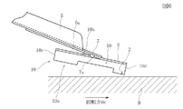
図1は、本発明の実施の形態の磁気ヘッド装置を、記録媒体との対向側を上に向けて示す斜視図、図2は、実施の形態の磁気ヘッド装置を、対向側から見た平面図である。図3と図4は実施の形態の磁気ヘッド装置の変形例を示す平面図である。図5は比較例となる磁気ヘッド装置を示す平面図である。図6は磁気ヘッド装置を支持する支持装置を示す側面図、図7は記録媒体と磁気ヘッド装置の対向状態を示す平面図である。図8ないし図10は実施例および比較例の磁気ヘッド装置の浮上特性を示す特性線図である。 FIG. 1 is a perspective view showing a magnetic head device according to an embodiment of the present invention with the side facing the recording medium facing upward, and FIG. 2 is a plan view of the magnetic head device according to the embodiment as viewed from the opposite side. FIG. 3 and 4 are plan views showing modifications of the magnetic head device according to the embodiment. FIG. 5 is a plan view showing a magnetic head device as a comparative example. FIG. 6 is a side view showing a support device for supporting the magnetic head device, and FIG. 7 is a plan view showing a facing state of the recording medium and the magnetic head device. 8 to 10 are characteristic diagrams showing the flying characteristics of the magnetic head devices of the examples and comparative examples.
図1と図2に示す実施の形態の磁気ヘッド装置1は、アルミナ・チタンカーバイトなどで形成された立方体形状のスライダ10と、このスライダ10に搭載された磁気機能部2とを有している。
A
磁気機能部2は、磁気抵抗効果(MR効果)や巨大磁気抵抗効果(GMR効果)あるいはトンネル磁気抵抗効果(TMR効果)を利用して、記録媒体Dに記録された磁気信号を読み取る読み取り機能部と、磁性材料のヨークや、導電性材料のコイルが薄膜プロセスで形成されて、記録媒体Dに磁気信号を書き込む記録機能部とを有している。
The
スライダ10は、記録媒体に対向する対向側10aと、この対向側10aと逆側に向く押圧側10bとを有している。また、スライダ10は、記録媒体Dの表面に発生する空気流の流入側に向くリーディング側端面10cと、前記空気流が流出するトレーリング側端面10dを有しており、前記磁気機能部2はトレーリング側端面10dに設けられている。また、スライダ10は、図7に示すハードディスクなどの磁気記録方式の記録媒体Dの回転中心側に向けられる内周側(ID側)の側面10eと、記録媒体の外周に向けられる外周側(OD側)の側面10fを有している。
The
本明細書では、リーディング側端面10cに向く方向を前方、またはリーディング側端面10cに向く端部を前端と呼び、トレーリング側端面10dに向く方向を後方、またはトレーリング側端面10dに向く端部を後端と呼ぶことがある。また、リーディング側端面10cおよびトレーリング側端面10dに平行な方向を左右方向と呼び、内周側の側面10eに向く側を左側、外周側の側面10fに向く側を右側と呼ぶことがある。
In this specification, the direction toward the leading
図2では、リーディング側端面10cおよびトレーリング側端面10dをそれぞれ二分して前後方向へ延びる仮想線を中心線O−Oとしている。磁気機能部2の中心は、この中心線O−O上に位置している。
In FIG. 2, an imaginary line extending in the front-rear direction by dividing the
図6に示すように、磁気ヘッド装置1を構成するスライダ10の押圧側10bは、支持装置によって支持される。この支持装置には、弾性支持部材であるロードビーム5が設けられている。このロードビーム5の基部には弾性変形部が設けられており、この弾性変形部の弾性力によって、スライダ10に対して記録媒体D方向への押圧力が与えられる。ロードビーム5の先部には、ロードビーム5よりも薄く且つばね性を発揮する弾性板で形成されたフレキシャ6が固定されており、このフレキシャ6に折り曲げられた支持片6aに、スライダ10の押圧側10bの面が接着固定される。
As shown in FIG. 6, the
ロードビーム5の先部には下向きに突出したピボット7が一体に形成されており、このピボット7が、スライダ10の押圧側10bの面に当接し、または前記支持片6aに当接している。前記ロードビーム5で発揮される弾性押圧力は、ピボット7とスライダ10の押圧側10bの面との当接点7aに集中して作用する。前記フレキシャ6の支持片6aは各方向へ変形可能であり、支持片6aに固定されているスライダ10は、前記ピボット7との当接点7aを支点として、姿勢を変化できるようになっている。この姿勢変化の主な方向は、前記中心線O−Oが傾くピッチ方向、および中心線O−O回りに左右へ傾くロール方向である。図6に示すようにリーディング端面10cが持ち上げられた浮上姿勢において記録媒体Dの表面との成す角度がピッチ角である。
A pivot 7 that protrudes downward is integrally formed at the tip of the
図2には、ピボット7とスライダ10との当接点7aが投影されて示されている。この当接点7aは、前記中心線O−O上に位置し、且つリーディング側端面10cとトレーリング側端面10dとのほぼ中点に位置している。
In FIG. 2, a
図1と図2に示すように、スライダ10の対向側10aには、正圧面とステップ面および負圧面がそれぞれ平面で形成されている。正圧面が記録媒体Dに最も近い平面であり、ステップ面は前記正圧面よりも押圧側10bに近い平面である。図1では、正圧面からステップ面までの深さ寸法がh1で示されている。負圧面はステップ面よりも押圧側10bに位置する平面であり、図1では、ステップ面から負圧面までの深さ寸法をh2で示している。深さ寸法h2は深さ寸法h1よりも十分に大きい。
As shown in FIGS. 1 and 2, a positive pressure surface, a step surface, and a negative pressure surface are formed on the opposing
スライダ10の対向側10aが記録媒体Dに対向した状態で、記録媒体Dが回転すると、記録媒体Dの表面に形成される空気流(エアーベアリング)により、主に正圧面に浮上力が作用する。ステップ面は正圧面の面積を調整するためのものであるが、前記空気流によってステップ面にもわずかに浮上力が作用し、または正圧面の後端とステップ面との間にわずかな負圧による記録媒体Dへの吸引力が作用することがある。しかしステップ面に作用する浮上力や吸引力は、スライダ10の浮上姿勢や浮上距離への影響がわずかである。前記深さ寸法h1は0.3μm以下程度である。
When the recording medium D rotates with the
ステップ面の後端と負圧面との境界付近には負圧が発生し、この負圧により、スライダ10に対して記録媒体Dに向けて接近させるようとする吸引力が作用する。そのため、前記深さ寸法h2は、1μm以上で5μm以下、好ましくは2.5μm以下である。
A negative pressure is generated in the vicinity of the boundary between the rear end of the step surface and the negative pressure surface, and a suction force is applied to the
すなわち、スライダ10の対向側は、主に前記正圧面、ステップ面および負圧面の3段階の平面で形成されている。なお、本明細書での前記平面とは、曲率半径が無限大の純粋な平面はもとより、曲率半径が非常に大きい曲面をも含む概念である。
That is, the opposite side of the
前記正圧面は、リーディング側に位置する第1の前方正圧面21aと第2の前方正圧面21b、トレーリング側端面10dのすぐ内側に位置する後方正圧面22、後方正圧面22よりも前方で且つ左右両側に位置する第1の後方側部正圧面25aおよび第2の後方側部正圧面25bに区分される。これら各正圧面は同一平面上に位置している。
The positive pressure surface is located in front of the first front
第1の前方正圧面21aと第2の前方正圧面21bは、中心線O−Oを挟んで左右に均等な位置に形成され、第1の前方正圧面21aと第2の前方正圧面21bは、互いに同じ形状であり同じ面積を有している。ただし、記録媒体の外周側よりも内周側の方が空気流の流速が遅いため、この流速差を加味して、第1の前方正圧面21aと第2の前方正圧面21bとの面積を若干異ならせて、例えば、第1の前方正圧面21aの面積を、第2の前方正圧面21bの面積よりもわずかに大きく設定してもよい。
The first front
後方正圧面22は、その左右方向の中心が、ほぼ中心線O−O上に位置している。後方正圧面22の面積は、第1の前方正圧面21aや第2の前方正圧面21bの面積よりも小さい。
The center of the rear
第1の前方正圧面21aと後方正圧面22との間には、一定の幅寸法で前後方向に連続して延びる連結面23aが設けられ、第2の前方正圧面21bと後方正圧面22との間には、一定の幅寸法で前後方向へ連続して延びる連結面23bが設けられている。連結面23aと23bは、第1の前方正圧面21aと第2の前方正圧面21bおよび後方正圧面22と同じ平面内に位置している。前記連続面23aと連続面23bとの間には、空気導入溝24が形成されている。この空気導入溝24は、第1の前方正圧面21aと第2の前方正圧面21bとの間で、前方に向けて開放されており、空気導入溝24の後端は、後方正圧面22との境界部で閉じられている。リーディング側端面10cから対向側10aに流れる空気は、この空気導入溝24内で後方へ直線的に導かれて後方正圧面22の表面に与えられる。したがって、後方正圧面22は、その面積が比較的小さくても磁気機能部3を記録媒体Dの表面から持ち上げるための浮上力を作用させることができる。
A connecting
第1の後方側部正圧面25aは、スライダ10の内周側の側面10eに近接した位置に形成されている。また第1の後方側部正圧面25aの前方には空気導入凹部26aが形成されている。第2の後方側部正圧面25bは、スライダ10の外周側の側面10fに近接した位置に形成され、その前方には空気導入凹部26bが形成されている。第1の後方側部正圧面25aと第2の後方側部正圧面25bは、第1の前方正圧面21aと第2の前方正圧面21bおよび後方正圧面22と同じ平面内に位置している。
The first rear side
第1の後方側部正圧面25aと第2の後方側部正圧面25bは、後方正圧面22と共に、スライダ10の後方部分の浮上距離を安定させるように作用し、さらに第1の後方側部正圧面25aと第2の後方側部正圧面25bは、中心線O−Oを挟んで左右両側に配置されているため、スライダ10の中心線O−O回りのロール姿勢を安定させるように機能している。
The first rear side
リーディング側端面10cの直ぐ内側で且つ左右両端部には、一対の突起27a,27bが形成されている。この突起27a,27bの表面は、第1の前方正圧面21aおよび第2の前方正圧面21bと同一面上に位置している。この突起27a,27bは、スライダ10の側面10e,10fと、リーディング側端面10cとの角部が、記録媒体Dの表面に直接当たるのを防止する機能を発揮している。
A pair of
ステップ面は、前方ステップ面31と、第1の中間ステップ面32aおよび第2の中間ステップ面32bと、第1の側部ステップ面33aおよび第2の側部ステップ面33bと、第1の後方ステップ面34aと第2の後方ステップ面34bを有している。これら各ステップ面は同一平面上に位置している。
The step surface includes a
前方ステップ面31は、リーディング側端面10cから第1の前方正圧面21aおよび第2の前方正圧面21bのそれぞれの前端までのほぼ全域に形成されている。また、前記空気導入溝24の底面は、前方ステップ面31と同じ平面で連続している。第1の中間ステップ面32aと第2の中間ステップ面32bは、第1の前方正圧面21aおよび第2の前方正圧面21bの後方に位置している。第1の中間ステップ面32aの左側端部には、後方に延びるリブ35aが一体に形成されており、第2の中間ステップ面32bの右側端部には、後方に延びるリブ35bが一体に形成されている。
The
第1の側部ステップ面33aと第2の側部ステップ面33bは、第1の後方側部正圧面25aおよび第2の後方側部正圧面25bの前方に位置している。第1の後方ステップ面34aと第2の後方ステップ面34bは、第1の後方側部正圧面25aおよび第2の後方側部正圧面25bの後方に位置している。
The first
第1の中間ステップ面32aの後方には負圧面41aが形成されており、第2の中間ステップ面32bの後方には負圧面41bが形成されている。左側の負圧面41aと右側の負圧面41bとの間は、分割部52によって分割されている。前記連結面23a,23bおよび空気導入溝24は、分割部52の上に形成されている。前記負圧面41aにより第1の負圧発生部51aが形成されている。この第1の負圧発生部51aでは、第1の中間ステップ面32aの後端とリブ35aと分割部52とで挟まれた部分で最も大きな負圧が発生する。前記負圧面41bにより第1の負圧発生部51bが形成されている。この第1の負圧発生部51bでは、第2の中間ステップ面32bの後端とリブ35bと分割部52とで挟まれた部分で最も大きな負圧が発生する。
A
第1の側部ステップ面33aと第2の側部ステップ面33bとの間には、前後方向に延びる分割部54が形成されている。この分割部54は、前記分割部52と連続して形成されている。第1の側部ステップ面33aと前記分割部54との間には、左右方向へ直線的に延びる堰部36aが形成されており、第2の側部ステップ面33bと前記分割部54との間には、左右方向へ直線的に延びる堰部36bが形成されている。堰部36aの表面と堰部36bの表面は、第1の側部ステップ面33aおよび第2の側部ステップ面33bと同一平面上に位置している。
A
第1の側部ステップ面33aと堰部36aおよび分割部54で囲まれた領域が第2の負圧発生部53aであり、第2の側部ステップ面33bと堰部36bおよび分割部54で囲まれた領域が第2の負圧発生部53bである。第2の負圧発生部53aと第2の負圧発生部53bでは、周囲を囲まれた領域が前後に長くなっており、負圧発生領域の前後方向の長さが、第1の負圧発生部51aおよび第1の負圧発生部51bの負圧発生領域の前後方向の長さよりも大きくなっている。よって、第2の負圧発生部53a,53bに作用する記録媒体Dへの吸引力は、第1の負圧発生部51a,51bに作用する記録媒体Dへの吸引力よりも大きい。
A region surrounded by the first
上記のように、第1の負圧発生部51aと第1の負圧発生部51bは左右に分割して配置され、第2の負圧発生部53aと第2の負圧発生部53bも左右に分割して配置されており、さらに第1の負圧発生部51a,51bと第2の負圧発生部53a,53bとが前後に分割されて形成されている。よって、スライダ10の対向側10aには、互いに独立し且つ前後左右に並んで配列する4箇所の負圧発生部が設けられている。
As described above, the first
図2に示すように、スライダ10のリーディング側端面10cからトレーリング側端面10dまでの長さ寸法をL0とし、第1の負圧発生部51a,51bの前端、すなわち第1の中間ステップ面32aと第2の中間ステップ面32bの後端から、リーディング側端面10cまでの距離をL1としたときに、L1/L0が、0.4を超えた値であり、好ましくは0.43以上で、さらに好ましくは0.5以上である。第1の負圧発生部51a,51bは、共にリーディング側端面10cからの距離が0.4×L0よりも後方、つまり、スライダ10の前後の中間点付近あるいはそれよりも後方に位置し、第2の負圧発生部53a,53bは第1の負圧発生部51a,51bよりもさらに後方に位置している。また、後方正圧面22は、第2の負圧発生部53a,53bよりも後方に位置しており、第1の後方側部正圧面25aと第2の後方側部正圧面25bは、第2の負圧発生部53a,53bと左右方向に並ぶ位置に配置されている。
As shown in FIG. 2, the length from the
また、第1の前方正圧面21aと第2の前方正圧面21bのそれぞれの後端は、スライダ10を前後に二分する中点よりも前方に位置しており、リーディング側端面10cから、第1の前方正圧面21aおよび第2の前方正圧面21bのそれぞれの前端までの距離L2は、前記L1/2に一致し、またはL1/2よりも大きくなっている。すなわち、第1の前方正圧面21aの前端および第2の前方正圧面21bの前端は、前方ステップ面31の前端から第1の中間ステップ面32aおよび第2の中間ステップ面32bの後端までの寸法の中点と同じ位置か、または前記中点よりも後方に位置している。
In addition, the rear ends of the first front
前記第1の負圧発生部51a,51bと第2の負圧発生部53a,53bが、スライダ10の前後の中間付近から後方に分布しているため、それに合わせて第1の前方正圧面21aと第2の前方正圧面21bも、リーディング側端面10cから後方に長く離れた位置となっており、また、第1の前方正圧面21aと第2の前方正圧面21bの面積もやや狭くなっている。
Since the first negative
例えば、リーディング側端面10cからトレーリング側端面10dまでの長さ寸法L0が1.24mm程度であり、側面10eから側面10fまでの幅寸法が約0.70mmである。図1と図2に示す実施の形態では、L1が0.65mmであり、L1/L0が0.524である。
For example, the length dimension L0 from the
図3に示す磁気ヘッド装置1Aのスライダ10Aは、実施の形態の変形例であり、リーディング側端面10cから、第1の負圧発生部51a,51bの前端までの距離L1が0.73mmであり、L1/L0は、0.589である。また、リーディング側端面10cから第1の前方正圧面21aと第2の前方正圧面21bの前端までの距離L2のL1に対する比L2/L1は0.5または0.5よりも大きい。第1の前方正圧面21aの後端と第2の前方正圧面21bの後端の位置は、図2に示す実施の形態と同じである。図3でのL2が図2でのL2よりも大きいため、第1の前方正圧面21aと第2の前方正圧面の面積は、図2に示す実施の形態よりも狭くなっている。すなわち、図3の変形例では、第1の負圧発生部51a,51bが図2の実施の形態よりもトレーリング側に移動していることに合わせて、第1の前方正圧面21aと第2の前方正圧面21bの面積が狭くなっている。
A
図4に示す磁気ヘッド装置1Bのスライダ10Bは、実施の形態の変形例であり、リーディング側端面10cから、第1の負圧発生部51a,51bの前端までの距離L1が0.54mmであり、L1/L0は、0.435である。また、リーディング側端面10cから第1の前方正圧面21aと第2の前方正圧面21bの前端までの距離L2のL1に対する比L2/L1は0.5または0.5よりも大きい。第1の前方正圧面21aの後端と第2の前方正圧面21bの後端の位置は、図2に示す実施の形態と同じである。図3でのL2が図2でのL2よりも小さいため、第1の前方正圧面21aと第2の前方正圧面の面積は、図2に示す実施の形態よりも広くなっている。すなわち、図4の変形例では、第1の負圧発生部51a,51bが図2の実施の形態よりもリーディング側に移動していることに合わせて、第1の前方正圧面21aと第2の前方正圧面21bの面積が広くなっている。
A
実施の形態の磁気ヘッド装置1では、スライダ10のリーディング側からトレーリング側に向かう空気流が、前方ステップ面31と記録媒体Dとの間に導入されることにより、記録媒体Dが始動した直後にリーディング側端面10cが持ち上がる。空気流がスライダ10の対向側10aと記録媒体Dとの間をリーディング側からトレーリング側に向けて通過することにより、図6に示すように、リーディング側端面10cがトレーリング側端面10dよりも記録媒体Dから離れ、前上がりの所定のピッチ角を有する浮上姿勢となる。
In the
このとき、第1の前方正圧面21aと第2の前方正圧面21bに正圧が発生し、記録媒体Dから離れようとする浮上力が作用する。また後方正圧面22および第1の後方側部正圧面25aと第2の後方側部正圧面25bにも浮上力が作用する。リーディング側から流れる空気は、空気導入溝24内を左右に分散しにくい状態で後方へ進んで、後方正圧面22に導かれるため、後方正圧面22には常に安定した正圧が発生し、浮上力が作用する。また第1の後方側部正圧面25aと第2の後方側部正圧面25bには、空気導入凹部26a,26bから空気が導かれるため、第1の後方側部正圧面25aと第2の後方側部正圧面25bにも安定した正圧が発生し、浮上力が作用する。
At this time, a positive pressure is generated on the first front
4箇所に区分された第1の負圧発生部51a,51bと第2の負圧発生部53a,53bにはそれぞれ負圧が発生し、この負圧発生部には、記録媒体Dに接近しようとする吸引力が作用する。
A negative pressure is generated in each of the first negative
スライダ10は、第1の前方正圧面21aおよび第2の前方正圧面21b、後方正圧面22、第1の後方側部正圧面25aと第2の後方側部正圧面25bに作用する浮上力で下から支えられた状態となるが、リーディング側から流れる空気が第1の前方正圧面21aおよび第2の前方正圧面21bを押し上げ、スライダ10は前記空気流に捲くれ上げられるようにして図6に示すように所定のピッチ角を有する浮上姿勢となる。また各正圧面に作用する浮上力と、第1の負圧発生部51a,51bおよび第2の負圧発生部53a,53bに作用する吸引力とのバランスにより、記録媒体Dからのトレーリング側端縁10dの浮上距離が低く設定され、低浮上姿勢を維持できるようになる。
The
また、第1の負圧発生部51a,51bと第2の負圧発生部53a,53bが4箇所に区分され、前後左右に独立した各負圧部に吸引力が作用するため、スライダ10に対して吸引力がバランスよく作用し、前記4箇所に作用する浮上力と前記4箇所に作用する吸引力とによって、スライダ10の浮上姿勢が安定する。
In addition, the first negative
高地で使用されまたは航空機内で使用されるなどして、使用環境の空気密度が低下すると、各正圧面に発生する正圧が低下し浮上力が低下する。一方において負圧発生部に作用する負圧も低下するため、吸引力が低下する。この浮上力の低下と吸引力の低下とのバランスによって、空気密度の低下に起因する浮上姿勢の変動とトレーリング側端面10dの浮上距離の低下が抑制される。
When the air density in the environment of use decreases, such as when used at high altitudes or in airplanes, the positive pressure generated on each pressure surface decreases and the levitation force decreases. On the other hand, since the negative pressure acting on the negative pressure generating portion is also reduced, the suction force is reduced. The balance between the decrease in the levitation force and the decrease in the suction force suppresses the variation in the levitation posture and the decrease in the levitation distance of the trailing
前記実施の形態の磁気ヘッド装置1および変形例の磁気ヘッド装置1A,1Bでは、第1の負圧発生部51a,51bが、リーディング側端面10cからトレーリング側端面1dまでの長さ寸法の0.4を超える位置よりも後方に配置され、さらに第2の負圧発生部53a,53bがトレーリング側に配置されている。そのため、空気密度が低下したときに、後方正圧面22と第1の後方側部正圧面25aおよび第2の後方側部正圧面25bに作用する浮上力と、後方領域に位置する各負圧発生部に作用する吸引力が、スライダ10の後方領域において、バランスをとるように作用する。よって空気密度の低下によるトレーリング側端面10dの浮上距離の低下を抑制できるようになる。
In the
また、第1の負圧発生部51a,51bと第2の負圧発生部53a,53bが後方に位置していることに合わせて、第1の前方正圧面21aと第2の前方正圧面21bが、リーディング側端面10cから離れた後方に位置し、しかも、第1の負圧発生部51a,51bと第2の負圧発生部53a,53bが後方に位置していることに合わせて、第1の前方正圧面21aと第2の前方正圧面21bの面積を狭くしている。よって、リーディング側端面10cが記録媒体Dの表面から過剰に持ち上げられることを抑制できる。すなわち、スライダ10のピッチ角が過剰となることによるトレーリング側端面10dの浮上距離の低下を抑制できるようになる。
In addition, the first front
さらに、第2の負圧発生部53a,53bの左右両側において、第1の後方側部正圧面25aと第2の後方側部正圧面25bに浮上力が作用するため、空気密度が低下したときに、この部分において、浮上力の低下と吸引力の低下のバランスを確保できるようになる。よって、空気密度が低下してもスライダ10の浮上姿勢と浮上距離の変動を抑制できる。
Furthermore, when the air density decreases because the levitation force acts on the first rear side
実施の形態の磁気ヘッド装置1および変形例の磁気ヘッド装置1A,1Bと同じ構造のスライダを想定したコンピュータ解析によるシミュレーションを行った。このシミュレーションでは、磁気ヘッド装置1のスライダ10の長辺を124mm、短辺を0.70mmとし、深さ寸法h1を0.15μm、深さ寸法h2を3μmとした。当接点7aに作用する記録媒体D方向への押圧力(ロード圧)を、19.6mNとし、記録媒体Dの回転数を3600rpmとした。
A simulation by computer analysis was performed assuming a slider having the same structure as the
スライダ10の全長L0に対するリーディング側端面10cから第1の負圧発生部51a,51bの前端までの距離L1の比であるL1/L0の値を変えた比較例および実施例についてシミュレーションを行った。図1と図2に示す実施の形態と図3と図4に示す変形例との関係で説明したように、比較例と各実施例とでは、第1の前方正圧面21aと第2の前方正圧面21bの後端の位置を共通にし、第1の負圧発生部51a,51bがトレーリング側に移動するに応じて、第1の前方正圧面21aと第2の前方正圧面21bの面積を小さくした。すなわち、比較例と各実施例では、1気圧での使用環境においては、記録媒体Dの表面からのトレーリング側端面10dの浮上距離がほぼ同じになるように設定し、この条件の基で、標高3048m(10キロフィート)での空気密度を想定したときの、トレーリング側端面10dの浮上距離を算出した。
A simulation was performed on a comparative example and an example in which the value of L1 / L0, which is the ratio of the distance L1 from the
以下の表1の実施例3は、図1と図2に示す実施の形態に相当し、実施例5は図3に示した変形例に相当し、実施例1は図4に示す変形例に相当している。 Example 3 in Table 1 below corresponds to the embodiment shown in FIGS. 1 and 2, Example 5 corresponds to the modification shown in FIG. 3, and Example 1 corresponds to the modification shown in FIG. It corresponds.
表1の最上欄は、比較例および各実施例の前記距離L1(mm)であり、第2欄は、L1/L0の比である。第3欄以下は、スライダの位置がID,MD,ODのときの標高差感度である。この標高差感度は、1気圧を想定したときのトレーリング側端面10dの浮上距離を「1」としたときの、標高3048mでの空気密度を想定したときのトレーリング側端面10dの浮上距離の前記「1」に対する比である。また、図8は横軸をL1/L0とし、縦軸を標高差感度として、表1の結果をグラフに表したものである。
The uppermost column of Table 1 is the distance L1 (mm) of the comparative example and each example, and the second column is the ratio of L1 / L0. The third column and below are elevation difference sensitivities when the slider position is ID, MD, or OD. This altitude difference sensitivity is defined as the flying distance of the trailing
なお、IDは、記録媒体の回転中心からスライダの中心線O−Oまでの距離が6.6mmであり、MDは11.6mm、ODは16.6mmである。 In the ID, the distance from the rotation center of the recording medium to the center line OO of the slider is 6.6 mm, MD is 11.6 mm, and OD is 16.6 mm.
記録媒体Dがハードディスクである場合に、標高差感度が0.8を超えれば実用上問題がなく、さらには0.84以上であることが好ましく、さらに好ましくは0.85以上である。 When the recording medium D is a hard disk, there is no practical problem if the altitude difference sensitivity exceeds 0.8, more preferably 0.84 or more, and even more preferably 0.85 or more.
表1および図8から、L1/L0が0.4以上、または0.4を超えることが好ましく、好ましくは0.43以上であり、さらに好ましくは0.5以上である。 From Table 1 and FIG. 8, L1 / L0 is preferably 0.4 or more, or more than 0.4, preferably 0.43 or more, and more preferably 0.5 or more.

図5は第2の比較例の磁気ヘッド装置100のスライダ110を示している。この第2の比較例は、図1と図2に示す実施の形態(前記実施例3)の堰部36a,36bを除去したものであり、第2の負圧発生部53a,53bを無くし、第1の負圧発生部51a,51bのみを残したものである。その他の構造は図1と図2に示す実施の形態と同じである。
FIG. 5 shows the
図9は、横軸が記録媒体Dの回転中心からスライダの中心線O−Oまでの距離であり、縦軸は1気圧を想定したときのトレーリング側端面の浮上距離を示している。図10は、横軸に記録媒体Dの回転中心からスライダの中心線O−Oまでの距離を示し、縦軸は1気圧を想定したときのロール角度(μrad)を示している。 In FIG. 9, the horizontal axis represents the distance from the rotation center of the recording medium D to the center line OO of the slider, and the vertical axis represents the flying distance of the trailing side end surface assuming 1 atm. In FIG. 10, the horizontal axis indicates the distance from the rotation center of the recording medium D to the center line OO of the slider, and the vertical axis indicates the roll angle (μrad) assuming 1 atm.
図9と図10から、実施の形態(実施例3)では磁気ヘッド装置がIDからODまでシークするときに浮上距離とロール角度が安定しているのに対し、第2の比較例では、浮上距離とロール角度が不安定になる。また第2の比較例では、標高差感度が、IDで0.73、MDで0.71、ODで0.69となり、実施例3よりも劣るものであった。 9 and 10, in the embodiment (Example 3), the flying distance and the roll angle are stable when the magnetic head device seeks from ID to OD, whereas in the second comparative example, the flying height The distance and roll angle become unstable. In the second comparative example, the altitude difference sensitivity was 0.73 for ID, 0.71 for MD, and 0.69 for OD, which was inferior to Example 3.
本実施の形態および実施例では、第1の負圧発生部51a,51bと第2の負圧発生部53a,53bを4箇所に独立して設け、しかも第1の負圧発生部51a,51bの前端を、スライダの全長L0の0.4倍の位置よりも後方に配置することにより、浮上姿勢とロール姿勢が安定し、空気密度が低下しても浮上距離の低下を抑制できるものとなる。
In the present embodiment and example, the first
1,1A,1B 磁気ヘッド装置
2 磁気機能部
7a 当接点(押圧力の作用点)
10 スライダ
10a 対向側
10b 押圧側
10c リーディング側端面
10d トレーリング側端面
21a 第1の前方正圧面
21b 第2の前方正圧面
22 後方正圧面
24 空気導入溝
25a 第1の後方側部正圧面
25b 第2の後方側部正圧面
31 前方ステップ面
32a 第1の中間ステップ面
32b 第2の中間ステップ面
33a 第1の側部ステップ面
33b 第2の側部ステップ面
34a 第1の後方ステップ面
34b 第2の後方ステップ面
41a,41b、42a,42b 負圧面
51a,51b 第1の負圧発生部
43a,53b 第2の負圧発生部
52,54 分割部
1, 1A, 1B
10
Claims (8)
前記スライダの対向側には、リーディング側に位置する前方正圧面と、トレーリング側に位置する後方正圧面と、前記前方正圧面よりも後方に位置する第1の負圧発生部と、前記第1の負圧発生部よりも後方に位置する第2の負圧発生部と、が設けられており、
前記スライダのリーディング側端面からトレーリング側端面までの長さ寸法に対する、前記リーディング側端面から前記第1の負圧発生部の前端までの距離の比が0.4を超えていることを特徴とする磁気ヘッド装置。 A slider having a side facing the recording medium and a pressing side on which a pressing force is applied toward the recording medium, and a magnet that is provided on the trailing side of the slider and exhibits at least one function of magnetic recording and magnetic reproduction In a magnetic head device having a functional part,
On the opposite side of the slider, a front positive pressure surface located on the leading side, a rear positive pressure surface located on the trailing side, a first negative pressure generating portion located rearward of the front positive pressure surface, and the first A second negative pressure generating unit located behind the first negative pressure generating unit,
The ratio of the distance from the leading side end surface to the front end of the first negative pressure generating portion with respect to the length dimension from the leading side end surface to the trailing side end surface of the slider exceeds 0.4. Magnetic head device.
Priority Applications (3)
| Application Number | Priority Date | Filing Date | Title |
|---|---|---|---|
| JP2005341521A JP2007149205A (en) | 2005-11-28 | 2005-11-28 | Magnetic head device |
| US11/562,592 US20070153420A1 (en) | 2005-11-28 | 2006-11-22 | Magnetic head unit capable of suppressing variation in floating distance from recording medium due to variation in air density of environment |
| CNB200610160463XA CN100442357C (en) | 2005-11-28 | 2006-11-28 | Magnetic head unit |
Applications Claiming Priority (1)
| Application Number | Priority Date | Filing Date | Title |
|---|---|---|---|
| JP2005341521A JP2007149205A (en) | 2005-11-28 | 2005-11-28 | Magnetic head device |
Publications (1)
| Publication Number | Publication Date |
|---|---|
| JP2007149205A true JP2007149205A (en) | 2007-06-14 |
Family
ID=38125886
Family Applications (1)
| Application Number | Title | Priority Date | Filing Date |
|---|---|---|---|
| JP2005341521A Pending JP2007149205A (en) | 2005-11-28 | 2005-11-28 | Magnetic head device |
Country Status (3)
| Country | Link |
|---|---|
| US (1) | US20070153420A1 (en) |
| JP (1) | JP2007149205A (en) |
| CN (1) | CN100442357C (en) |
Cited By (2)
| Publication number | Priority date | Publication date | Assignee | Title |
|---|---|---|---|---|
| US7961432B2 (en) | 2008-12-12 | 2011-06-14 | Kabushiki Kaisha Toshiba | Head, head suspension assembly, and disk drive provided with the same |
| JP2011123949A (en) * | 2009-12-10 | 2011-06-23 | Hitachi Global Storage Technologies Netherlands Bv | Magnetic head slider and magnetic disk device |
Families Citing this family (3)
| Publication number | Priority date | Publication date | Assignee | Title |
|---|---|---|---|---|
| JP4957378B2 (en) * | 2007-05-23 | 2012-06-20 | Tdk株式会社 | Magnetic head device |
| JP2019145190A (en) * | 2018-02-22 | 2019-08-29 | 株式会社東芝 | Head gimbal assembly and magnetic disk device provided therewith |
| JP2019145195A (en) * | 2018-02-23 | 2019-08-29 | 株式会社東芝 | Head gimbal assembly and magnetic disk device provided therewith |
Family Cites Families (8)
| Publication number | Priority date | Publication date | Assignee | Title |
|---|---|---|---|---|
| JPH08249639A (en) * | 1995-03-07 | 1996-09-27 | Sony Corp | Flying type head slider and disk drive equipment |
| US6021020A (en) * | 1996-10-28 | 2000-02-01 | Kabushiki Kaisha Toshiba | Head slider and read/write apparatus using same |
| US6989967B2 (en) * | 2002-08-06 | 2006-01-24 | Seagate Technology Llc | Slider having a trailing bearing pad adjacent to a recessed area |
| JP3889374B2 (en) * | 2003-04-10 | 2007-03-07 | アルプス電気株式会社 | Magnetic head device and magnetic disk device using the magnetic head device |
| JP4057982B2 (en) * | 2003-09-02 | 2008-03-05 | 株式会社東芝 | Contact-type magnetic head slider, magnetic head assembly, and magnetic recording apparatus |
| US7277255B2 (en) * | 2003-10-21 | 2007-10-02 | Matsushita Electric Industrial Co., Ltd. | Head slider with positive dynamic pressure generating section |
| JP2005228362A (en) * | 2004-02-10 | 2005-08-25 | Matsushita Electric Ind Co Ltd | Slider and magnetic disk unit |
| JP4293933B2 (en) * | 2004-03-31 | 2009-07-08 | 富士通株式会社 | Head slider of disk device |
-
2005
- 2005-11-28 JP JP2005341521A patent/JP2007149205A/en active Pending
-
2006
- 2006-11-22 US US11/562,592 patent/US20070153420A1/en not_active Abandoned
- 2006-11-28 CN CNB200610160463XA patent/CN100442357C/en not_active Expired - Fee Related
Cited By (2)
| Publication number | Priority date | Publication date | Assignee | Title |
|---|---|---|---|---|
| US7961432B2 (en) | 2008-12-12 | 2011-06-14 | Kabushiki Kaisha Toshiba | Head, head suspension assembly, and disk drive provided with the same |
| JP2011123949A (en) * | 2009-12-10 | 2011-06-23 | Hitachi Global Storage Technologies Netherlands Bv | Magnetic head slider and magnetic disk device |
Also Published As
| Publication number | Publication date |
|---|---|
| CN1975865A (en) | 2007-06-06 |
| US20070153420A1 (en) | 2007-07-05 |
| CN100442357C (en) | 2008-12-10 |
Similar Documents
| Publication | Publication Date | Title |
|---|---|---|
| JP4252059B2 (en) | Magnetic head device | |
| JP4041510B2 (en) | Magnetic head device | |
| US7719795B2 (en) | Head having a transducer heater and an air bearing surface with a flow-diversion dam and pressure-relief trough disposed upstream of the transducer | |
| US7616405B2 (en) | Slider with an air bearing surface having a inter-cavity dam with OD and ID dam surfaces of different heights | |
| JP2006302452A (en) | Head, head suspension assembly, and disk device provided with the same | |
| JP2004310955A (en) | Magnetic head device and magnetic disk unit using the same | |
| US7499245B2 (en) | Magnetic head slider having stepped surfaces | |
| JP2007242121A (en) | Magnetic head device | |
| JP4041509B2 (en) | Magnetic head slider | |
| JP2007149205A (en) | Magnetic head device | |
| JP5687334B2 (en) | Magnetic head slider device and magnetic disk device | |
| JP2009110618A (en) | Head slider | |
| JP4293933B2 (en) | Head slider of disk device | |
| JP4204587B2 (en) | Magnetic head device | |
| JP2004164685A (en) | Flying head slider and disk storage using the same | |
| JP4893469B2 (en) | Magnetic head device | |
| US7990656B2 (en) | Magnetic head device | |
| JP4962138B2 (en) | Magnetic head device | |
| JP2007287287A (en) | Magnetic head slider and magnetic disk device | |
| JP4734402B2 (en) | Head slider of disk device | |
| JP5214784B2 (en) | Head, head suspension assembly, and disk device including the same | |
| JP2009015891A (en) | Head, head suspension assembly, and disk device equipped with the same | |
| JP2005149702A (en) | Head slider and disk device with the same | |
| JP2008065861A (en) | Magnetic head slider | |
| JPH11339418A (en) | Floating magnetic head |
Legal Events
| Date | Code | Title | Description |
|---|---|---|---|
| A711 | Notification of change in applicant |
Free format text: JAPANESE INTERMEDIATE CODE: A711 Effective date: 20080108 |
|
| A521 | Written amendment |
Free format text: JAPANESE INTERMEDIATE CODE: A821 Effective date: 20080111 |
|
| RD02 | Notification of acceptance of power of attorney |
Free format text: JAPANESE INTERMEDIATE CODE: A7422 Effective date: 20080111 |
|
| A977 | Report on retrieval |
Free format text: JAPANESE INTERMEDIATE CODE: A971007 Effective date: 20080918 |
|
| A131 | Notification of reasons for refusal |
Free format text: JAPANESE INTERMEDIATE CODE: A131 Effective date: 20080924 |
|
| A02 | Decision of refusal |
Free format text: JAPANESE INTERMEDIATE CODE: A02 Effective date: 20090203 |