JP2007148420A - Image display device and portable terminal device using the same - Google Patents
Image display device and portable terminal device using the same Download PDFInfo
- Publication number
- JP2007148420A JP2007148420A JP2007001771A JP2007001771A JP2007148420A JP 2007148420 A JP2007148420 A JP 2007148420A JP 2007001771 A JP2007001771 A JP 2007001771A JP 2007001771 A JP2007001771 A JP 2007001771A JP 2007148420 A JP2007148420 A JP 2007148420A
- Authority
- JP
- Japan
- Prior art keywords
- lens
- pixel
- image
- display panel
- light
- Prior art date
- Legal status (The legal status is an assumption and is not a legal conclusion. Google has not performed a legal analysis and makes no representation as to the accuracy of the status listed.)
- Granted
Links
Images


Abstract
Description
本発明は、レンチキュラレンズ又はフライアイレンズ等のレンズを使用し、複数の視点に向けて相互に異なる画像を表示することができる画像表示装置及びそれを使用した携帯端末装置に関し、特に反射表示において明るさの低下がなく、表示品質が優れた画像表示装置及びそれを使用した携帯端末装置に関する。 The present invention relates to an image display device that uses a lens such as a lenticular lens or a fly-eye lens and can display images different from each other toward a plurality of viewpoints, and a portable terminal device using the image display device. The present invention relates to an image display device having no reduction in brightness and excellent display quality, and a portable terminal device using the image display device.
従来より、立体画像を表示することができる表示装置の検討が行われている。紀元前280年にギリシャの数学者ユークリッドは「立体視とは、同一物体の異なる方向から眺めた別々の映像を左右両眼が同時に見ることによって得られる感覚である」と考察している(例えば、非特許文献1:増田千尋著「3次元ディスプレイ」産業図書株式会社)。即ち、立体画像表示装置の機能としては、左右両眼に視差のある画像を夫々提示することが必要となる。 Conventionally, a display device capable of displaying a stereoscopic image has been studied. In 280 BC, Greek mathematician Euclid considers that "stereoscopicity is the sense that the left and right eyes simultaneously see different images viewed from different directions of the same object" (for example, Non-Patent Document 1: Chihiro Masuda “3D Display” Sangyo Tosho Co., Ltd.). That is, as a function of the stereoscopic image display device, it is necessary to present images with parallax to both the left and right eyes.
この機能を具体的に実現する方法として、従来より多くの立体画像表示方式が検討されているが、これらは眼鏡を使用する方式と眼鏡を使用しない方式に大別することができる。このうち、眼鏡を使用する方式には、色の違いを利用したアナグリフ方式、及び偏光を利用した偏光眼鏡方式等があるが、本質的に眼鏡をかける煩わしさを避けることができないため、近年では眼鏡を使用しない眼鏡なし方式が盛んに検討されている。 As a method for concretely realizing this function, more stereoscopic image display methods have been studied than before, but these methods can be roughly divided into a method using glasses and a method using no glasses. Among these, there are anaglyph methods that use the difference in colors and polarized glasses methods that use polarized light, etc., but in recent years, the inconvenience of wearing glasses cannot be avoided. A method without glasses that does not use glasses has been actively studied.
眼鏡なし方式には、レンチキュラレンズ方式、パララックスバリア方式等がある。レンチキュラレンズ方式はIves等により1910年頃に発明されたとされている。パララックスバリア方式は、1896年にBerthierが着想し、1903年にIvesによって実証されたとされている。 Examples of the method without glasses include a lenticular lens method and a parallax barrier method. The lenticular lens system is invented around 1910 by Ives et al. The parallax barrier method was conceived by Berthier in 1896 and was proven by Ives in 1903.
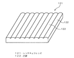
レンチキュラレンズ方式は、例えば前述の非特許文献1に記載されているように、Ives等により1910年頃に発明された。図22はレンチキュラレンズ121を示す斜視図であり、図23はレンチキュラレンズを使用する立体表示方法を示す光学モデル図である。図22に示すように、レンチキュラレンズ121は一方の面が平面となっており、他方の面には、一方向に延びるかまぼこ状の凸部(シリンドリカルレンズ)122が、その長手方向が相互に平行になるように複数個形成されている。
The lenticular lens system was invented around 1910 by Ives et al., For example, as described in Non-Patent
そして、図23に示すように、観察者側から順に、レンチキュラレンズ121、表示パネル106、光源108が配置されており、レンチキュラレンズ121の焦点面に表示パネル106の画素が位置している。表示パネル106においては、右眼141用の画像を表示する画素123と左眼142用の画像を表示する画素124とが交互に配列されている。このとき、相互に隣接する画素123及び画素124からなる群は、レンチキュラレンズ121の各凸部122に対応している。これにより、光源108から出射し各画素を透過した光は、レンチキュラレンズ121の凸部122により左右の眼に向かう方向に振り分けられる。これにより、左右の眼に相互に異なる画像を認識させることが可能となり、観察者に立体画像を認識させることが可能になる。
As shown in FIG. 23, a
一方、パララックスバリア方式は、1896年にBerthierが着想し、1903年にIvesによって実証された。図24は、パララックスバリアを使用する立体画像表示方法を示す光学モデル図である。図24に示すように、パララックスバリア105は、細い縦縞状の多数の開口、即ち、スリット105aが形成されたバリア(遮光板)である。そして、このパララックスバリア105の一方の表面の近傍には、表示パネル106が配置されている。表示パネル106においては、スリットの長手方向と直交する方向に右眼用画素123及び左眼用画素124が配列されている。また、パララックスバリア105の他方の表面の近傍、即ち、表示パネル106の反対側には、光源108が配置されている。
On the other hand, the parallax barrier method was conceived by Berthier in 1896 and proved by Ives in 1903. FIG. 24 is an optical model diagram showing a stereoscopic image display method using a parallax barrier. As shown in FIG. 24, the
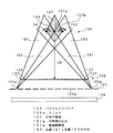
光源108から出射され、パララックスバリア105の開口(スリット105a)を通過し、右眼用画素123を透過した光は、光束181となる。同様に、光源108から出射され、スリット105aを通過し、左眼用画素124を通過した光は光束182となる。このとき、立体画像の認識が可能となる観察者の位置は、パララックスバリア105と画素との位置関係により決定される。即ち、観察者の右眼141は、複数の右眼用画素123に対応する全ての光束181の通過域内にあり、且つ、観察者の左眼142は、全ての光束182の通過域内にあることが必要となる。これは、図24において、観察者の右眼141と左眼142との中点143が図24に示す四角形の立体可視域107内に位置する場合である。立体可視域107における右眼用画素123及び左眼用画素124の配列方向に延びる線分のうち、立体可視域107における対角線の交点107aを通る線分が最も長い線分となる。このため、中点143が交点107aに位置するとき、観察者の位置が左右方向にずれた場合の許容度が最大となるため、観察位置としては最も好ましい。従って、この立体画像表示方法においては、この交点107aと表示パネル106との距離を最適観察距離ODとし、この距離で観察することを観察者に推奨している。なお、立体可視域107における表示パネル106からの距離が最適観察距離ODとなる仮想的な平面を、最適観察面107bという。これにより、観察者の右眼141及び左眼142に夫々右眼用画素123及び左眼用画素124からの光が到達することになる。このため、観察者は表示パネル106に表示された画像を、立体画像として認識することが可能になる。
Light that is emitted from the
パララックスバリア方式は、当初考案された際には、パララックスバリアが画素と眼との間に配置されていたこともあり、目障りで視認性が低い点が問題であった。しかし、近時の液晶表示装置の実現に伴って、図24に示すように、パララックスバリア105を表示パネル106の裏側に配置することが可能となって視認性が改善された。このため、パララックスバリア方式の立体画像表示装置については、現在盛んに検討が行われている。
When the parallax barrier method was originally devised, the parallax barrier was disposed between the pixels and the eyes, which was problematic because it was unsightly and low in visibility. However, with the recent realization of liquid crystal display devices, the
しかし、パララックスバリア方式が不要な光線をバリアにより「隠す」方式であるのに対し、レンチキュラレンズ方式は光の進む向きを変える方式であり、レンチキュラレンズ方式は、原理的に表示画面の明るさの低下がないという利点を有する。そのため、特に高輝度表示及び低消費電力性能が重視される携帯機器等への適用が検討されつつある。なお、従来のレンチキュラレンズを使用した立体画像表示装置は、透過型液晶表示装置を表示パネルとして使用している。 However, while the parallax barrier method is a method that “hides” unnecessary rays by the barrier, the lenticular lens method changes the light traveling direction, and in principle the brightness of the display screen is the lenticular lens method. There is an advantage that there is no decrease in For this reason, application to portable devices and the like where high brightness display and low power consumption performance are particularly important is being studied. Note that a stereoscopic image display device using a conventional lenticular lens uses a transmissive liquid crystal display device as a display panel.
また、レンチキュラレンズを使用した画像表示装置として、立体画像表示装置の他にも、複数の画像を同時に表示する複数画像同時表示装置が開発されている(例えば、特許文献1参照。)これは、レンチキュラレンズによる画像の振分機能を利用して、観察する方向毎に異なる画像を同時に同一条件で表示するディスプレイである。これにより、1台の複数画像同時表示装置が、この表示装置に対して相互に異なる方向に位置する複数の観察者に対して、相互に異なる画像を同時に提供することができる。特許文献1には、この複数画像同時表示装置を使用することにより、通常の1画像表示装置を同時に表示したい画像の数だけ用意する場合と比較して、設置スペース及び電気代を削減できると記載されている。
As an image display device using a lenticular lens, in addition to a stereoscopic image display device, a multiple image simultaneous display device that simultaneously displays a plurality of images has been developed (see, for example, Patent Document 1). This is a display that simultaneously displays different images for each viewing direction under the same conditions using the image distribution function of the lenticular lens. Thereby, one multiple image simultaneous display apparatus can provide mutually different images simultaneously to a plurality of observers positioned in mutually different directions with respect to the display apparatus.
また、従来より、反射板を有する反射型平面画像表示装置を表示パネルに使用することが検討されている。反射型表示装置は、外部から入射した光を表示装置内部に位置する反射板により反射し、この反射光を表示光源として利用するため、光源としてのバックライト又はサイドライトが不要になる。一方、透過型表示装置はバックライト又はサイドライト等の光源が必要である。従って、表示パネルに反射型表示装置を使用すると、透過型表示装置を使用した場合よりも、低消費電力化を達成できる。このため、近年では携帯機器等への反射型表示装置の適用が進められている。 Conventionally, the use of a reflection type flat image display device having a reflection plate for a display panel has been studied. In the reflective display device, light incident from the outside is reflected by a reflecting plate located inside the display device, and this reflected light is used as a display light source, so that a backlight or sidelight as a light source is not necessary. On the other hand, a transmissive display device requires a light source such as a backlight or a sidelight. Therefore, when a reflective display device is used for the display panel, lower power consumption can be achieved than when a transmissive display device is used. For this reason, in recent years, the application of reflective display devices to portable devices and the like has been promoted.
しかしながら、このように、反射型表示装置を使用した場合は、反射板の形状が平坦面であるときには、外光は鏡面のように反射されるため、例えば蛍光灯等の光源の模様が映り込み、表示品質が低下するという問題がある。また、観察者に対し、ある特定の角度からの入射光しか表示に寄与しなくなるため、外光の利用効率が低下するという問題がある。 However, when the reflective display device is used in this way, when the shape of the reflector is a flat surface, the external light is reflected like a mirror surface, so that a pattern of a light source such as a fluorescent lamp is reflected. There is a problem that the display quality deteriorates. In addition, since only the incident light from a specific angle contributes to the display for the observer, there is a problem that the utilization efficiency of external light is reduced.
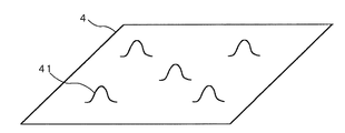
このため、特開平8−184846号公報(特許文献2)に記載のように、反射板に凹凸形状を設ける技術が提案されている。図25は凹凸形状を有する反射板の構造例を示す。反射板4の下層に有機膜を設け、その有機膜の表面に凹凸を形成することにより、反射板4の表面に凹凸形状41を形成している。この凹凸形状により、特定方向から入射した外光は、種々の方向に拡散して反射される。また、種々の方向から入射した外光は、観察者方向にも反射される。この結果、光源模様の映り込みを防止し、種々の角度を有する外光を表示に活用できることになる。
For this reason, as described in JP-A-8-184846 (Patent Document 2), a technique for providing a concavo-convex shape on a reflecting plate has been proposed. FIG. 25 shows an example of the structure of a reflector having an uneven shape. An
このように、レンチキュラレンズを使用した立体画像表示装置と、反射型平面表示装置とは、それ自体は夫々公知である。 As described above, the stereoscopic image display device using the lenticular lens and the reflective flat display device are known per se.
しかしながら、これらのレンチキュラレンズを使用した立体画像表示装置と、反射型平面表示装置は、いずれも低消費電力であるという利点があるにも拘わらず、両者を組み合わせた立体画像表示装置は従来存在しなかった。 However, although a stereoscopic image display device using these lenticular lenses and a reflective flat display device both have the advantage of low power consumption, there is a conventional stereoscopic image display device that combines the two. There wasn't.
そこで、本発明者らは、前述の立体画像表示装置と反射型平面表示装置とを組み合わせることにより、反射表示において立体画像表示が可能な表示装置を実現し、低消費電力化を図るべく、鋭意検討した。この結果、以下に示すような新たな問題点が明らかになった。 Accordingly, the present inventors have eagerly realized a display device capable of displaying a stereoscopic image in a reflective display by combining the above-described stereoscopic image display device and a reflective flat display device, and reducing power consumption. investigated. As a result, the following new problems became clear.
即ち、本来ならほぼ一様な輝度を有する筈の立体可視域において、観察位置によっては部分的に輝度が低下する領域が発生するという問題である。観察位置を変化させると、輝度が低下した位置では表示が暗くなって見え、場合によっては暗線の模様が観察される。また、この輝度のムラによって、立体画像表示の品質が低下してしまう。 That is, there is a problem that a region where the luminance is partially reduced occurs depending on the observation position in the three-dimensional visible region of the eyelid that has a substantially uniform luminance. When the observation position is changed, the display appears dark at the position where the luminance is lowered, and a dark line pattern is observed in some cases. In addition, the unevenness of luminance deteriorates the quality of stereoscopic image display.
この問題について説明する前に、先ず、従来の透過型液晶表示パネルとレンチキュラレンズを使用した立体画像表示装置について説明する。図26は2眼式の立体画像表示装置を示した斜視図である。レンチキュラレンズ3を構成する一つのシリンドリカルレンズは、表示パネル2の2画素(左眼用画素51、右眼用画素52)に対応して配置されている。図27に示すように、表示素子の左眼用画素51又は右眼用画素52からの光は、レンチキュラレンズ3により屈折し、夫々領域EL又はERに向けて出射する。このため、観察者が左眼61を領域ELに位置させ、右眼62を領域ERに位置させることにより、左眼61に左眼用の画像が入力されると共に、右眼62に右眼用の画像が入力され、立体画像を認識することができる。
Before describing this problem, first, a conventional stereoscopic image display device using a transmissive liquid crystal display panel and a lenticular lens will be described. FIG. 26 is a perspective view showing a twin-lens stereoscopic image display device. One cylindrical lens constituting the
次に、レンチキュラレンズを使用した立体画像表示装置の各部のサイズについて、図28に示す光学モデルを使用して説明する。レンチキュラレンズ3の表面の凸部中心と表示画素との間隔をHとし、レンチキュラレンズ3の屈折率をnとする。なお、レンチキュラレンズ3の表面の凸部中心とは、レンチキュラレンズ3の頂点のことである。レンチキュラレンズ3の片面は平面となっており、他の片面には凸型のシリンドリカルレンズ、即ち一方向に延びるかまぼこ状の凸部31が多数配列されているものとする。このレンチキュラレンズ3の焦点距離はfとし、レンズピッチはLとする。表示素子2の画素は、各1個の左眼用画素51及び右眼用画素52が1組になって配置されている。各画素のピッチはPとする。1つの凸部31に対して各1個の左眼用画素51及び右眼用画素52の2画素からなる組が対応している。また、レンチキュラレンズ3と観察者との間の距離をODとし、この距離ODにおける画素の拡大投影幅、即ち、レンズから距離ODだけ離れレンズと平行な仮想平面上における左眼用画素51及び右眼用画素52の投影像の幅を夫々eとする。更に、レンチキュラレンズ3の中央に位置する凸部31の中心から、レンチキュラレンズ3の端に位置する凸部31の中心までの距離をWLとし、表示素子2の中心に位置する左眼用画素51と右眼用画素52の対の中心と、表示素子2の端に位置する画素対の中心との距離をWPとする。更にまた、レンチキュラレンズ3の中央に位置する凸部31における光の入射角及び出射角を夫々α及びβとし、レンチキュラレンズ3の端に位置する凸部31における光の入射角及び出射角を夫々γ及びδとする。距離WLと距離WPとの差をCとし、距離WPの領域に含まれる画素数を2m個とする。
Next, the size of each part of the stereoscopic image display device using the lenticular lens will be described using the optical model shown in FIG. The interval between the center of the convex portion on the surface of the
通常、表示素子に合わせてレンチキュラレンズを設計する場合が多いので、Pは定数として扱う。また、レンチキュラレンズの材料を選択することにより、nが決定される。これに対して、レンズと観察者との間の距離OD及び観察距離ODにおける画素拡大投影幅eは所望の値を設定する。これらの値を使用して、レンズ面と画素との間の距離H及びレンズピッチLを決定する。スネルの法則と幾何学的関係より、下記数式1乃至6が成立する。また、下記数式7乃至9が成立する。
Usually, since a lenticular lens is often designed in accordance with a display element, P is treated as a constant. Further, n is determined by selecting the material of the lenticular lens. On the other hand, the distance OD between the lens and the observer and the pixel enlarged projection width e at the observation distance OD are set to desired values. These values are used to determine the distance H and lens pitch L between the lens surface and the pixel. From Snell's law and geometrical relationships, the following

上記数式2、1及び3より、夫々下記数式10、11及び12が成立する。
From the
また、上記数式6及び9より下記数式13が成立する。また、上記数式7乃至9より、下記数式14が成立する。更に、上記数式5より、下記数式15が成立する。
Further, the following formula 13 is established from the
なお、下記数式16に示すように、通常はレンチキュラレンズ表面の凸部中心と画素との間隔Hを焦点距離fと等しく配置するので、レンズの曲率半径rは下記数式17により求まる。
As shown in the following formula 16, since the distance H between the center of the convex portion of the lenticular lens surface and the pixel is usually set equal to the focal length f, the curvature radius r of the lens can be obtained by the following
次に、上記設計に基づき、市販の光線追跡シミュレータを使用して、立体画像表示装置の計算機シミュレーションを行った。図29は、このシミュレーションに使用する光学モデルを示す図である。本例では、画素ピッチPが0.24mmである表示素子を仮定し、レンチキュラレンズ3の材料として屈折率nが1.49であるポリメチルメタクリレート(PMMA)を使用し、レンズと観察者との距離ODを280mmとし、距離ODにおける画素拡大投影幅eを65mmとし、mの値を60と設定すると、上記各数式により、レンズ面と画素との距離Hは1.57mm、レンズの焦点距離fは1.57mm、レンズピッチLは0.4782mm、レンズの曲率半径rは0.5161mmとすれば良いことがわかる。これにより、受光面18は、レンズ面から280mmの位置に配置したことになる。また、画素ピッチP=0.24mmであるから、画素の幅は0.24mmである。そして、画素の中央部に発光領域17を配置した。発光領域17の幅は0.186mmに設定した。従って、発光領域17の両側には幅が夫々0.027mmの非表示領域が設けられている。発光領域17が発光する光は拡散光とした。非表示領域は、表示装置の混色を防止したり、画素に表示信号を伝送したりする目的で配置される遮光部に相当する。更に、シミュレーションを容易にするために、表示素子中心付近に位置する右眼用のひとつの画素のみ設定した。
Next, based on the above design, a computer simulation of a stereoscopic image display apparatus was performed using a commercially available ray tracing simulator. FIG. 29 is a diagram showing an optical model used for this simulation. In this example, a display element having a pixel pitch P of 0.24 mm is assumed, and polymethyl methacrylate (PMMA) having a refractive index n of 1.49 is used as the material of the
図30は、レンズ表面から距離OD=280mmだけ離れた観察面における観察位置を横軸にとり、縦軸にこの観察位置における照度をとって、このシミュレーションの結果を示したグラフ図である。横軸の観察位置の−60mmから0mmの範囲の照度が高くなっており、その値は概ね一様である。即ち、この範囲に右眼を配置した場合、右眼には十分な量の光が入射し、左眼には光がほとんど入射しない。これは、実際の立体画像表示装置において、左眼用画素に左眼用画像を表示させ、右眼用画素に右眼用画像を表示させた場合、左眼には左眼用画像が入力され、右眼には右眼用画像が入力され、両画像の分離が十分に確保され、この結果観察者は立体画像を良好に認識できることを意味する。 FIG. 30 is a graph showing the results of this simulation, with the horizontal axis representing the observation position on the observation surface separated from the lens surface by the distance OD = 280 mm, and the vertical axis representing the illuminance at this observation position. The illuminance in the range from −60 mm to 0 mm at the observation position on the horizontal axis is high, and the value is substantially uniform. That is, when the right eye is placed in this range, a sufficient amount of light is incident on the right eye and almost no light is incident on the left eye. In an actual stereoscopic image display device, when a left eye image is displayed on a left eye pixel and a right eye image is displayed on a right eye pixel, the left eye image is input to the left eye. The right-eye image is input to the right eye, and separation of both images is sufficiently ensured, which means that the observer can recognize the stereoscopic image well.
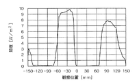
次に、上述の立体表示装置を反射型表示にすべく、画素の発光領域を反射板に設定して計算機シミュレーションを行った。図31は、このシミュレーションに使用する光学モデルを示す図である。凹凸形状41は反射板4の一部にのみ設定したが、これは平坦部との差異を明らかにするためである。具体的には、斜面角度30°、高さ2μmの突起を、反射板の中心に対しピッチ10μmで3列設けた。光源19は、全てのレンズを覆う横幅に設定し、レンズ表面から1mmの位置に配置した。光源19の光は拡散光である。図32は、このシミュレーション結果を示したグラフ図である。−30mmの位置に照度低下が発生していることがわかる。即ち、この位置で観察した場合には表示が暗くなって観察されてしまうという問題がある。
Next, in order to make the above-described stereoscopic display device a reflective display, a computer simulation was performed with the light emitting region of the pixel set to a reflector. FIG. 31 is a diagram showing an optical model used for this simulation. The concave /
また、上記のシミュレーションではあるひとつの画素について取り上げたが、一般的には凹凸形状は全ての表示画素にわたってランダムな位置に存在する。そうすると、表示装置の各画素によって明るさが異なって観察されるため、立体画像に明るさの違いが重畳して観察される。この結果、立体画像表示の品質が低下するという問題がある。なお、このような問題点は、立体画像表示装置に限らず、前述の複数画像同時表示装置等のような複数の視点に対して相互に異なる画像を同時に表示する表示装置には一般的に発生する。 Moreover, although one pixel was taken up in the above simulation, in general, the concavo-convex shape exists at random positions over all display pixels. Then, since the brightness is observed differently for each pixel of the display device, the difference in brightness is superimposed on the stereoscopic image and observed. As a result, there is a problem that the quality of the stereoscopic image display is deteriorated. Such a problem is not limited to a stereoscopic image display device, but generally occurs in a display device that simultaneously displays different images from a plurality of viewpoints such as the above-described multiple image simultaneous display device. To do.
本発明はかかる問題点に鑑みてなされたものであって、反射表示において明るさが低下せず、表示品質が優れた画像表示装置及びそれを使用した携帯端末を提供することを目的とする。 The present invention has been made in view of such problems, and an object of the present invention is to provide an image display device which has excellent display quality and brightness is not lowered in reflective display, and a portable terminal using the image display device.
本願第1発明に係る画像表示装置は、1表示単位に第1視点用の画像を表示する画素及び第2視点用の画像を表示する画素を少なくとも含む複数個の表示単位がマトリクス状に配置された表示パネルと、この表示パネルの前方に配置され前記各画素から出射した光を屈折させて相互に異なる方向に出射する複数個のレンズ素子が形成されたレンズと、前記表示パネル内又は前記表示パネルの後方に配置され外光を前記レンズに向けて反射すると共に表面に凹凸形状を有する反射板と、を有し、前記レンズの焦点距離fが前記反射板の表面と前記レンズの頂点との間の距離Hと異なることを特徴とする。 In the image display device according to the first aspect of the present invention, a plurality of display units including at least a pixel for displaying an image for a first viewpoint and a pixel for displaying an image for a second viewpoint are arranged in a matrix in one display unit. A display panel, a lens formed in front of the display panel and formed with a plurality of lens elements that refract light emitted from the pixels and emit the light in different directions, and the display panel or the display A reflective plate disposed behind the panel and reflecting external light toward the lens and having a concavo-convex shape on the surface, and a focal length f of the lens is between the surface of the reflective plate and the apex of the lens It is different from the distance H between.
本発明においては、レンズにより集光された光が、反射板の表面で、ある一定の面積を有するため、凹凸形状の斜面及び平坦部等、複数の種類の傾斜角で反射され、反射光は様々な角度に進行する。この一部分は観察者方向にも進行するため、表示に寄与することができる。これにより、凹凸形状に起因する輝度低下を防止することができる。 In the present invention, since the light collected by the lens has a certain area on the surface of the reflecting plate, it is reflected at a plurality of types of inclination angles such as uneven slopes and flat parts, and the reflected light is Proceed to various angles. This part also proceeds in the direction of the observer, and can contribute to display. Thereby, the brightness | luminance fall resulting from uneven | corrugated shape can be prevented.
本願第2発明に係る画像表示装置は、1表示単位に透過領域及び反射領域を備え第1視点用の画像を表示する画素並びに透過領域及び反射領域を備え第2視点用の画像を表示する画素を少なくとも含む複数個の表示単位がマトリクス状に配置された表示パネルと、この表示パネルの前方に配置され前記各画素から出射した光を屈折させて相互に異なる方向に出射する複数個のレンズ素子が形成されたレンズと、前記表示パネルの前記透過領域に光を照射する光源と、前記表示パネル内の反射領域又は前記表示パネルの反射領域の後方に配置され外光を前記レンズに向けて反射すると共に表面に凹凸形状を有する反射板と、を有し、前記レンズの焦点距離fが前記反射板の表面と前記レンズの頂点との間の距離Hと異なることを特徴とする。 The image display device according to the second aspect of the present invention is a pixel that includes a transmission region and a reflection region in one display unit and displays a first viewpoint image, and a pixel that includes a transmission region and a reflection region and displays a second viewpoint image. And a plurality of lens elements that are arranged in front of the display panel and refract light emitted from the pixels and emit the light in different directions. And a light source that irradiates light to the transmission area of the display panel, and a reflection area in the display panel or a rear area of the reflection area of the display panel that reflects external light toward the lens. And a reflecting plate having a concavo-convex shape on the surface, the focal length f of the lens being different from the distance H between the surface of the reflecting plate and the apex of the lens.
この画像表示装置においても、反射領域においては、レンズにより集光された光がある一定の面積を有するため、凹凸形状の斜面及び平坦部等、複数の種類の傾斜角で反射され、反射光は様々な角度に進行する。この一部分は観察者方向にも進行するため、表示に寄与することができ、これにより、凹凸形状に起因する輝度低下を防止することができる。 Also in this image display device, the light collected by the lens has a certain area in the reflection region, and thus is reflected at a plurality of types of inclination angles such as uneven slopes and flat parts, and the reflected light is Proceed to various angles. Since this part also proceeds in the direction of the viewer, it can contribute to display, thereby preventing a decrease in luminance due to the uneven shape.
本発明に係る画像表示装置において、前記レンズの焦点距離が前記反射板とレンズとの距離より小さいことが好ましい。 In the image display device according to the present invention, it is preferable that a focal length of the lens is smaller than a distance between the reflecting plate and the lens.
更に、本発明に係る画像表示装置は、前記レンズのピッチをLとし、前記凹凸形状の最小ピッチをVとするとき、前記レンズの焦点距離f、及び前記反射板の表面とレンズの頂点との間の距離Hが数式18を満たすことが好ましい。
Furthermore, in the image display device according to the present invention, when the pitch of the lens is L and the minimum pitch of the concavo-convex shape is V, the focal length f of the lens and the surface of the reflector and the vertex of the lens It is preferable that the distance H between the two satisfies
更に、本発明に係る画像表示装置は、最適観察距離をODとし、前記最適観察距離ODにおける画素の拡大投影幅をeとし、前記レンズの屈折率をnとし、表示素子の画素ピッチをPとするとき、前記レンズの焦点距離fが下記数式19乃至21を満たすことが好ましい。
Furthermore, the image display device according to the present invention has an optimum observation distance as OD, an enlarged projection width of a pixel at the optimum observation distance OD as e, a refractive index of the lens as n, and a pixel pitch of the display element as P. In this case, it is preferable that the focal length f of the lens satisfies the following
これにより、本発明においては、凹凸形状に起因する輝度低下をより抑制することができる。 Thereby, in this invention, the luminance fall resulting from uneven | corrugated shape can be suppressed more.
本発明に係る画像表示装置は、前記最適観察距離OD、前記画素拡大投影幅e、前記レンズの屈折率n、前記反射板の表面とレンズの表面の凸部中心との間の距離H、及び表示素子の画素ピッチPが前記数式19乃至20及び下記数式22を満たすことが好ましい。
The image display device according to the present invention includes the optimum observation distance OD, the pixel enlargement projection width e, the refractive index n of the lens, the distance H between the surface of the reflector and the center of the convex portion of the lens surface, and It is preferable that the pixel pitch P of the display element satisfies the
本発明においては、レンズ面と画素間の距離が固定である場合にも適用することができ、かつ凹凸形状に起因する輝度低下を抑制することができる。 In the present invention, the present invention can be applied even when the distance between the lens surface and the pixel is fixed, and the luminance reduction due to the uneven shape can be suppressed.
本発明に係る画像表示装置は、前記レンズの焦点距離が前記反射板の表面と前記レンズの頂点との間の距離Hより大きいように構成することができる。 The image display device according to the present invention can be configured such that the focal length of the lens is greater than the distance H between the surface of the reflector and the apex of the lens.
更に、本発明に係る画像表示装置は、前記レンズの焦点距離f、前記反射板の表面と前記レンズの頂点との間の距離H、前記レンズピッチL、及び前記凹凸形状の最小ピッチVが下記数式23を満たすことが好ましい。 Furthermore, in the image display device according to the present invention, the focal length f of the lens, the distance H between the surface of the reflector and the apex of the lens, the lens pitch L, and the minimum pitch V of the uneven shape are as follows: It is preferable to satisfy Equation 23.
更に、本発明に係る画像表示装置は、前記最適観察距離OD、前記画素拡大投影幅e、前記レンズの屈折率n、前記レンズの焦点距離f、及び表示素子の画素ピッチPが前記数式19乃至21を満たすことが好ましい。本発明においては、レンズ面と画素間の距離を小さくすることができる。これにより、画像表示装置の総厚を小さくすることができる。
Furthermore, in the image display device according to the present invention, the optimum observation distance OD, the pixel enlargement projection width e, the refractive index n of the lens, the focal length f of the lens, and the pixel pitch P of the display element are represented by the
更に、本発明に係る画像表示装置は、前記最適観察距離OD、前記画素拡大投影幅e、前記レンズの屈折率n、前記反射板の表面と前記レンズの頂点との間の距離H、及び表示素子の画素ピッチPが前記数式19乃至20及び22を満たすことが好ましい。本発明においては、焦点距離を大きく設定することができる。これにより、レンズの凹凸の高さを小さくすることができるため、レンズの模様が目立ちにくくなり、画像の表示品質が向上する。
Furthermore, the image display device according to the present invention includes the optimum observation distance OD, the pixel enlargement projection width e, the refractive index n of the lens, the distance H between the surface of the reflector and the vertex of the lens, and the display. It is preferable that the pixel pitch P of the element satisfies the
本願第3発明に係る画像表示装置は、1表示単位に第1視点用の画像を表示する画素及び第2視点用の画像を表示する画素を少なくとも含む複数個の表示単位がマトリクス状に配置された表示パネルと、この表示パネルの前方に配置され前記各画素から出射した光を屈折させて相互に異なる方向に出射する複数個のレンズ素子が形成されたレンズと、前記表示パネル内又は前記表示パネルの後方に配置され外光を前記レンズに向けて反射すると共に表面に凹凸形状を有する反射板と、を有し、前記反射板の表面の凹凸形状が入射する光を複数回反射するような形状を有することを特徴とする。 In the image display device according to the third aspect of the present invention, a plurality of display units including at least a pixel for displaying an image for a first viewpoint and a pixel for displaying an image for a second viewpoint are arranged in a matrix in one display unit. A display panel, a lens formed in front of the display panel and formed with a plurality of lens elements that refract light emitted from the pixels and emit the light in different directions, and the display panel or the display A reflective plate disposed behind the panel and reflecting external light toward the lens and having a concavo-convex shape on the surface, and the concavo-convex shape on the surface of the reflective plate reflects the incident light multiple times. It has a shape.
本願第4発明に係る画像表示装置は、1表示単位に透過領域及び反射領域を備え第1視点用の画像を表示する画素並びに透過領域及び反射領域を備え第2視点用の画像を表示する画素を含む複数個の表示単位がマトリクス状に配置された表示パネルと、この表示パネルの前方に配置され前記各画素から出射した光を屈折させて相互に異なる方向に出射する複数個のレンズ素子が形成されたレンズと、前記表示パネルの前記透過領域に光を照射する光源と、前記表示パネル内の反射領域又は前記表示パネルの反射領域の後方に配置され外光を前記レンズに向けて反射すると共に表面に凹凸形状を有する反射板と、を有し、前記反射板の表面の凹凸形状が入射する光を複数回反射するような形状を有することを特徴とする。 The image display device according to the fourth aspect of the present invention is a pixel that includes a transmission region and a reflection region in one display unit and displays an image for a first viewpoint, and a pixel that includes a transmission region and a reflection region and displays an image for a second viewpoint. A display panel in which a plurality of display units are arranged in a matrix, and a plurality of lens elements that are arranged in front of the display panel and refract light emitted from the pixels and emit the light in different directions. The formed lens, a light source that irradiates light to the transmissive area of the display panel, and a reflection area in the display panel or a rear area of the reflection area of the display panel that reflects external light toward the lens And a reflecting plate having a concavo-convex shape on the surface, and the concavo-convex shape on the surface of the reflecting plate has a shape that reflects incident light a plurality of times.
本発明においては、凹凸形状のひとつの斜面で反射した光の一部分は、別の斜面で再反射した後に、観察者の方向に進行することができる。これにより、凹凸形状に起因する輝度低下を防止することができる。 In the present invention, a part of the light reflected by one slope of the concavo-convex shape can travel in the direction of the observer after being re-reflected by another slope. Thereby, the brightness | luminance fall resulting from uneven | corrugated shape can be prevented.
更に、本発明に係る画像表示装置においては、前記凹凸形状の傾斜角が50°以上であることが好ましい。これにより、凹凸形状に起因する輝度低下をより抑制することができる。 Furthermore, in the image display device according to the present invention, it is preferable that the concavo-convex shape has an inclination angle of 50 ° or more. Thereby, the brightness fall resulting from uneven | corrugated shape can be suppressed more.
本願第5発明に係る画像表示装置は、1表示単位に第1視点用の画像を表示する画素及び第2視点用の画像を表示する画素を少なくとも含む複数個の表示単位がマトリクス状に配置された表示パネルと、この表示パネルの前方に配置され前記各画素から出射した光を屈折させて相互に異なる方向に出射する複数個のシリンドリカルレンズが形成されたレンチキュラレンズと、前記表示パネル内又は前記表示パネルの後方に配置され外光を前記レンズに向けて反射すると共に表面に凹凸形状を有する反射板と、を有し、前記シリンドリカルレンズの配列方向において、前記凹凸形状におけるある傾斜角を持つ斜面の存在確率が前記画素中で均一となっていることを特徴とする。 In the image display device according to the fifth aspect of the present invention, a plurality of display units including at least a pixel for displaying an image for a first viewpoint and a pixel for displaying an image for a second viewpoint are arranged in a matrix in one display unit. A display panel, a lenticular lens formed in front of the display panel and formed with a plurality of cylindrical lenses that refracts the light emitted from the pixels and emits the light in different directions; A reflector that is disposed behind the display panel and reflects external light toward the lens and has a concavo-convex shape on a surface thereof, and has an inclination angle in the concavo-convex shape in the arrangement direction of the cylindrical lenses. The existence probability is uniform in the pixels.
本願第6発明に係る画像表示装置は、1表示単位に透過領域及び反射領域を備え第一視点用の画像を表示する画素並びに透過領域及び反射領域を備え第二視点用の画像を表示する画素を含む複数個の表示単位がマトリクス状に配置された表示パネルと、この表示パネルの前方に配置され前記各画素から出射した光を屈折させて相互に異なる方向に出射する複数個のシリンドリカルレンズが形成されたレンチキュラレンズと、前記表示パネルの前記透過領域に光を照射する光源と、前記表示パネル内の反射領域又は前記表示パネルの反射領域の後方に配置され外光を前記レンズに向けて反射すると共に表面に凹凸形状を有する反射板と、を有し、前記シリンドリカルレンズの配列方向において、前記凹凸形状におけるある傾斜角を持つ斜面の存在確率が前記画素中で均一となっていることを特徴とする。 The image display device according to the sixth aspect of the present invention is a pixel that includes a transmission area and a reflection area in one display unit and displays an image for a first viewpoint, and a pixel that includes a transmission area and a reflection area and displays an image for a second viewpoint. A display panel in which a plurality of display units are arranged in a matrix, and a plurality of cylindrical lenses that are arranged in front of the display panel and refract light emitted from the pixels and emit the light in different directions. The formed lenticular lens, a light source that irradiates light to the transmission area of the display panel, and a reflection area in the display panel or a rear area of the reflection area of the display panel that reflects external light toward the lens And a reflector having a concavo-convex shape on the surface, and a slope having a certain inclination angle in the concavo-convex shape in the arrangement direction of the cylindrical lenses. Probability characterized in that it is uniform in the pixels.
シリンドリカルレンズは、その長手方向においてレンズ効果を持たないため、各画素における凹凸形状の光学的な効果は、シリンドリカルレンズの長手方向における効果を積分したものになる。従って、凹凸形状におけるある傾斜角を持つ斜面の存在確率を画素中で均一とすれば、前記光学的特性は、シリンドリカルレンズの配列方向における全ての位置において、同じ傾斜角が連続的に配置された場合と等価になる。この結果、凹凸形状に起因する輝度低下を防止することができる。 Since the cylindrical lens does not have a lens effect in the longitudinal direction, the optical effect of the uneven shape in each pixel is obtained by integrating the effect in the longitudinal direction of the cylindrical lens. Therefore, if the existence probability of a slope having a certain inclination angle in the concavo-convex shape is made uniform in the pixel, the same inclination angle is continuously arranged at all positions in the arrangement direction of the cylindrical lenses. It is equivalent to the case. As a result, it is possible to prevent a decrease in luminance due to the uneven shape.
更に、本発明に係る画像表示装置は、前記シリンドリカルレンズの長手方向における前記凹凸形状のピッチが、前記シリンドリカルレンズの配列方向における前記凹凸形状のピッチより小さいことが好ましい。これにより、凹凸形状を一画素中により密に配置することができるため、画素ピッチが小さな高精細パネルへの適用が容易になる。 Furthermore, in the image display device according to the present invention, it is preferable that the pitch of the uneven shape in the longitudinal direction of the cylindrical lens is smaller than the pitch of the uneven shape in the arrangement direction of the cylindrical lenses. Thereby, since the uneven shape can be arranged more densely in one pixel, application to a high-definition panel having a small pixel pitch is facilitated.
本発明に係る画像表示装置において、前記レンズがレンチキュラレンズ又はフライアイレンズであることが好ましい。また、前記表示装置が液晶表示装置であっても良い。 In the image display device according to the present invention, it is preferable that the lens is a lenticular lens or a fly-eye lens. The display device may be a liquid crystal display device.
本発明に係る携帯端末装置は、前述の画像表示装置を有することを特徴とする。また、この携帯端末装置は、携帯電話、携帯端末、PDA(Personal Digital Assistance:携帯型情報端末)、ゲーム機、デジタルカメラ又はデジタルビデオであってもよい。 A portable terminal device according to the present invention includes the above-described image display device. The mobile terminal device may be a mobile phone, a mobile terminal, a PDA (Personal Digital Assistance), a game machine, a digital camera, or a digital video.
本発明によれば、レンズにより集光された光が、反射板の表面で、ある一定の面積を有するため、凹凸形状の斜面及び平坦部等、複数の種類の傾斜角で反射され、反射光は様々な角度に進行する。この一部分は観察者方向にも進行するため、表示に寄与することができる。これにより、凹凸形状に起因する輝度低下を防止することができ、反射表示において明るさの低下がなく、優れた表示品質を有する画像表示装置を得ることができる。 According to the present invention, since the light collected by the lens has a certain area on the surface of the reflector, it is reflected at a plurality of types of inclination angles such as uneven slopes and flat parts, and reflected light. Proceeds at various angles. This part also proceeds in the direction of the observer, and can contribute to display. As a result, it is possible to prevent a decrease in luminance due to the uneven shape, and it is possible to obtain an image display device having excellent display quality without a decrease in brightness in reflective display.
以下、本発明の実施形態について添付の図面を参照して具体的に説明する。 Hereinafter, embodiments of the present invention will be specifically described with reference to the accompanying drawings.
(第1の実施形態)
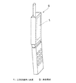
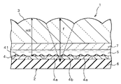
図1は本発明の第1の実施形態に係る立体画像表示装置の断面図であり、図2は本実施形態に係る携帯端末装置を示す斜視図である。立体画像表示装置1は反射型液晶表示パネル2とレンチキュラレンズ3より構成される。反射型液晶表示パネル2は、基板6と透明基板7との間に、液晶層5が挟まれて構成されており、基板6の液晶層側の表面に画素電極(反射板4)が形成され、透明基板7の液晶層側の表面に対向電極(図示せず)が形成されている。これらの画素電極及び対向電極は相互に直交する方向に延びる線状の電極であり、この画素電極と対向電極とが交差する位置の画素を選択して両者間に電圧を印加して液晶の配向を制御し、画像表示するようになっている。
(First embodiment)
FIG. 1 is a cross-sectional view of a stereoscopic image display device according to a first embodiment of the present invention, and FIG. 2 is a perspective view showing a mobile terminal device according to the present embodiment. The stereoscopic
本実施形態においては、液晶層5の背面側に配置された画素電極により反射板4が構成されている。この反射板は凹凸形状41を有する。この凹凸形状41の大きさは、従来の反射型液晶表示装置の反射板の凹凸形状と同様であるが、一例として、2μmの高さ、及び10μmのピッチを有する。
In the present embodiment, the
透明基板7の上には、レンチキュラレンズ3が配置されている。このレンチキュラレンズ3は、凸部31が一定のピッチで現れる湾曲した表面(シリンドリカル面)が多数形成されており、このシリンドリカル面の長手方向(湾曲中心軸線が延びる方向)は、本実施形態では、画素電極(反射板4)が延びる方向に平行である。また、このシリンドリカル面は、2個の画素(画素電極4)について1個配置されるものである。
A
本実施形態では、画素は、前述の如く、1個の左眼用画素4aと、1個の右眼用画素4bとから1表示単位が構成され、各表示単位において、左眼用画素から出射された光と、右眼用画素から出射された光とが、レンチキュラレンズ3の対応する1個のシリンドリカルレンズにより左眼と右眼とに向けて振り分けられる。この場合に、外光はレンチキュラレンズ3、透明基板7及び液晶層5を透過して、液晶層5の下面に位置する反射板4にて反射し、再度、液晶層5、透明基板7及びレンチキュラレンズ3を透過する。このとき、反射板4に対し、特定方向から入射した外光は、反射板4の表面の凹凸形状41により、種々の方向に拡散して反射し、観察者方向にも反射する。これにより、光源模様の映り込みを防止し、種々の角度を有する外光を表示に活用できることができる。
In the present embodiment, as described above, one display unit is composed of one left-
而して、本実施形態においては、レンチキュラレンズ3の表面の凸部31中心と、反射板4の表面、つまり画素との間の距離HRは、前記数式10乃至12により算出される従来の光学モデルでのレンチキュラレンズ3の表面の凸部中心と画素との間の距離Hよりも大きく設定されている。この結果、レンズ面と画素との間の距離HRは、レンチキュラレンズ3の焦点距離fより大きい。即ち、本実施形態においては、レンチキュラレンズ3の焦点距離fは、前記数式10乃至12及び16により算出される。このとき、観察距離ODは、例えば、以下のように定義される最適観察距離である。この最適観察距離とは、観察者の右眼と左眼との中点を位置させることにより前記右眼に前記右眼用の画像を表示する画素から出射した光が入射すると共に前記左眼に前記左眼用の画像を表示する画素から出射した光が入射する立体可視域における1表示単位内の左眼用画素4aと右眼用画素4bとを結ぶ方向に延びる線分のうち最も長い線分と、反射型液晶表示パネル2との間の距離である。
Thus, in the present embodiment, the distance HR between the center of the
この立体画像表示装置1は、例えば、図2に示すような携帯電話9の画像表示に使用される。
The stereoscopic
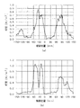
次に、本発明の効果を説明するために行った計算機シミュレーションの結果について説明する。図3は計算機シミュレーションに使用した光学モデルを示す。図31の従来の光学モデルではレンズ表面(凸部中心)と画素との間の距離HRが1.57mmに設定され、レンズの焦点距離f=1.57mmと等しい。これに対し、図3の本発明の光学モデルではレンズの表面(凸部中心)と画素との間の距離HRが1.77mmに設定され、レンズの焦点距離f=1.57mmより大きい点が図31の場合と異なる。 Next, the results of a computer simulation performed to explain the effects of the present invention will be described. FIG. 3 shows an optical model used for computer simulation. In the conventional optical model of FIG. 31, the distance HR between the lens surface (convex center) and the pixel is set to 1.57 mm, which is equal to the focal length f of the lens = 1.57 mm. On the other hand, in the optical model of the present invention shown in FIG. 3, the distance HR between the lens surface (convex center) and the pixel is set to 1.77 mm, and the lens focal length f is greater than 1.57 mm. This is different from the case of FIG.
図4(a)は図3の光学モデルを使用した場合のシミュレーション結果を示すグラフ図であり、本発明を適用した場合の結果である。これに対し、比較例として、図31の従来の光学モデルを使用した場合のシミュレーション結果を図4(b)に示す。これらの図によれば、図4(b)で生じていた−30mm付近での輝度低下が、図4(a)では大幅に緩和されていることがわかる。従って、−30mm付近で観察しても表示が暗くなることはない。 FIG. 4A is a graph showing a simulation result when the optical model of FIG. 3 is used, and is a result when the present invention is applied. On the other hand, as a comparative example, FIG. 4B shows a simulation result when the conventional optical model of FIG. 31 is used. According to these figures, it can be seen that the decrease in luminance in the vicinity of −30 mm, which has occurred in FIG. 4B, is greatly alleviated in FIG. 4A. Therefore, the display does not become dark even when observed in the vicinity of −30 mm.
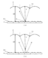
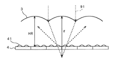
図5(a)及び(b)は、本発明の原理について、定性的に説明するための概念図である。このうち、図5(a)は、図31に示す光学モデルにおいて、入射する外光のうち、ある平行光成分の光線91の軌跡を示した概念図である。レンズ面と画素との間の距離Hが焦点距離fと等しくなるように配置されているため、レンチキュラレンズ3により集光された光91は、反射板4の表面で焦点を結び、凹凸形状の斜面で反射されると、観察者の方向とは異なる方向に進行する。このため、実質的に表示には寄与しない。これに対して、図5(b)に示す本発明の光学モデルでは、レンズ面と画素間の距離HRが焦点距離fより大きく設定されているために、レンチキュラレンズ3により集光された光は反射板4上で、ある一定の面積を有する。この結果、凹凸形状の斜面及び平坦部等、複数の種類の傾斜角で反射されるので、反射光は種々の角度に進行する。この一部分は観察者方向にも進行するため、表示に寄与することができる。従って、本発明によれば、輝度低下を防止することができる。
5A and 5B are conceptual diagrams for qualitatively explaining the principle of the present invention. Among these, FIG. 5A is a conceptual diagram showing a trajectory of a
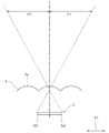
レンズ面と画素との間の距離HRに関しては、図6に示すように、レンチキュラレンズ3により集光された光が、複数の傾斜角の斜面を照射することが特に好ましい。この結果、反射光の角度分布をより広範囲にでき、観察者方向に反射する割合を高めることができるからである。本条件は、凹凸形状のピッチをVとすると、レンズピッチLを底辺とし、焦点距離fを高さとする三角形と、底辺が凹凸形状のピッチVであり、高さがレンズ面と画素間の距離HRから焦点距離fを差し引いた値である三角形との間に相似の関係が成り立つ。従って、レンズにより集光された光が複数の傾斜角の斜面を照射するための条件は、下記数式24にて表される。これを変形すると、下記数式25が得られる。
Regarding the distance HR between the lens surface and the pixel, as shown in FIG. 6, it is particularly preferable that the light collected by the
即ち、数式25を満たすようにレンズ面と画素間の距離HRを設定するのが好ましい。また、凹凸形状の位置がランダムである場合には、凹凸形状のピッチのうち最小のものをVとすることで、本発明を適用することができる。 That is, it is preferable to set the distance HR between the lens surface and the pixel so as to satisfy Formula 25. In addition, when the position of the uneven shape is random, the present invention can be applied by setting V as the smallest pitch of the uneven shape.
本発明における表示素子は、画素電極に凹凸形状を有する反射板が存在すれば良い。本発明の実施形態では、反射型液晶表示素子を用いた場合について説明したが、これに限定されることはなく、例えば電気泳動現象を利用した表示素子を利用することができる。また、凹凸形状は、斜面を有する構造であれば適用可能であり、点状、棒状、窪み状などその全体的な形状には左右されない。また、画素電極の駆動方法は、TFT方式及びTFD方式等のアクティブマトリクス方式でも良いし、STN方式等のパッシブマトリクス方式でも適用可能である。 In the display element according to the present invention, it is only necessary that the pixel electrode has a reflection plate having an uneven shape. In the embodiment of the present invention, the case where the reflective liquid crystal display element is used has been described. However, the present invention is not limited to this, and for example, a display element using an electrophoretic phenomenon can be used. The uneven shape is applicable to any structure having a slope, and is not affected by the overall shape such as a dot shape, a rod shape, or a depression shape. The pixel electrode driving method may be an active matrix method such as a TFT method or a TFD method, or a passive matrix method such as an STN method.
また、上述の説明はレンチキュラレンズの場合について行ったが、フライアイレンズへの適用もできることは勿論である。図7はフライアイレンズ10を示す斜視図である。レンチキュラレンズ3が、図22に示すように、一方向に延びるシリンドリカルレンズ3が相互に平行に配置された形状を有し、1表示単位における左眼用画素と右眼用画素とを結ぶ方向に、つまり左右方向に凸面が繰り返され、この左右方向に直交するレンチキュラレンズ3の長手方向には、その表面は変化しない。つまり、左右方向に延びる断面の形状は、レンチキュラレンズ3の長手方向には変化しない。これに対し、フライアイレンズ10は左眼用画素と右眼用画素とを結ぶ方向と、この方向に直交する方向とのいずれの方向にも凸面が繰り返される。つまり、1表示単位における左眼用画素と右眼用画素とが対向する方向(左右方向)については、この1組の左眼用画素と右眼用画素とに対して1個の凸面が配置される点は、レンチキュラレンズの場合と同様であるが、フライアイレンズは、前記左右方向に直交する方向にも、2画素(右眼用の2画素又は左眼用の2画素)毎に1個の凸面が配置されている。
Further, the above description has been given for the case of a lenticular lens, but it goes without saying that it can also be applied to a fly-eye lens. FIG. 7 is a perspective view showing the fly-
これにより、フライアイレンズの場合は、立体画像表示装置を立てて、これを観察しているときに、左右の眼に専用の画像を表示して立体視を可能とすることの他に、上下方向にも画像を振り分けて視野角を広げたり、観察者が画像の上下側面を観ることができるようにすることもできる。このように、レンズにフライアイレンズ10を使用した場合にも、上記実施形態と同様に、そのレンズの焦点距離fが反射板の表面とレンズの表面の凸部中心との間の距離Hと異なるようにすることにより、上記実施形態と同様の効果を得ることができる。
As a result, in the case of a fly-eye lens, when a stereoscopic image display device is set up and observed, a dedicated image is displayed on the left and right eyes to enable stereoscopic viewing. It is also possible to distribute the image in the direction to widen the viewing angle, or to allow the observer to see the upper and lower sides of the image. Thus, even when the fly-
また、上述の説明は、レンズの凸部が観察者側になるように配置された場合についてのものであるが、レンズの凸部が表示装置側になるように配置された場合でおいても、同様の効果を得ることができる。 In addition, the above description is about the case where the convex portion of the lens is arranged on the viewer side, but even when the convex portion of the lens is arranged on the display device side. The same effect can be obtained.
本実施形態に係る立体画像表示装置は、携帯電話等の携帯機器に好適に適用することができ、良好な立体画像を表示することができる。本実施形態に係る立体画像表示装置を携帯機器に適用すれば、大型の表示装置に適用する場合と異なり、観察者が自分の両眼と表示画面との位置関係を任意に調節できるため、最適な可視域を速やかに見出すことができる。 The stereoscopic image display apparatus according to the present embodiment can be suitably applied to a portable device such as a mobile phone, and can display a favorable stereoscopic image. If the stereoscopic image display device according to the present embodiment is applied to a mobile device, unlike the case of applying to a large display device, the observer can arbitrarily adjust the positional relationship between his eyes and the display screen, which is optimal. A visible region can be quickly found.
また、本実施形態に係る立体画像表示装置は携帯電話のみならず、携帯端末、PDA、ゲーム機、デジタルカメラ、デジタルビデオカメラ等の携帯端末装置に適用することができる。 The stereoscopic image display apparatus according to the present embodiment can be applied not only to mobile phones but also to mobile terminal devices such as mobile terminals, PDAs, game machines, digital cameras, and digital video cameras.
(第2の実施形態)
図8は本発明の第2の実施形態に係る立体画像表示装置の断面図である。本実施形態は、前述の第1の実施形態と比較して、レンズ面と画素間の距離HRが、前記数式10乃至12により算出される従来の光学モデルでのレンズ面と画素間距離HRよりも小さく設定されている点が異なる。この結果、レンズ面と画素間の距離HRは、レンチキュラレンズの焦点距離fより小さい。
(Second Embodiment)
FIG. 8 is a cross-sectional view of a stereoscopic image display apparatus according to the second embodiment of the present invention. In the present embodiment, the distance HR between the lens surface and the pixel is compared with the distance HR between the lens surface and the pixel in the conventional optical model calculated by
本実施形態におけるレンズ面と画素間の距離HRに関しては、図9に示すように、レンズにより集光された光が、複数の傾斜角の斜面を照射するのが特に好ましい。この結果、反射光の角度分布をより広範囲にでき、観察者方向に反射する割合を高めることができるからである。本条件は、凹凸形状のピッチをVとすると、幾何学的関係より、レンズ面と画素間の距離HR、焦点距離f、レンズピッチLを用いて、下記数式26にて表される。これを変形すると下記数式27が得られる。 Regarding the distance HR between the lens surface and the pixel in the present embodiment, as shown in FIG. 9, it is particularly preferable that the light condensed by the lens irradiates a slope having a plurality of inclination angles. As a result, the angular distribution of reflected light can be made wider, and the ratio of reflection in the observer direction can be increased. This condition is expressed by the following formula 26 using the distance HR between the lens surface and the pixel, the focal length f, and the lens pitch L from the geometrical relationship, where V is the pitch of the concavo-convex shape. When this is modified, the following Expression 27 is obtained.
即ち、数式27を満たすようにレンズ面と画素間の距離HRを設定することが好ましい。また、凹凸形状の位置がランダムである場合には、凹凸形状のピッチのうち最小のものをVとすることで、本発明を適用することができる。 That is, it is preferable to set the distance HR between the lens surface and the pixel so as to satisfy Expression 27. In addition, when the position of the uneven shape is random, the present invention can be applied by setting V as the smallest pitch of the uneven shape.
本発明によれば、本発明の第1の実施形態と比較して、レンズ面と画素間の距離を小さくすることができる。したがって、立体画像表示装置の総厚を小さくすることができるため、携帯電話等の携帯端末に好適に使用することができる。 According to the present invention, the distance between the lens surface and the pixel can be reduced as compared with the first embodiment of the present invention. Therefore, since the total thickness of the stereoscopic image display device can be reduced, it can be suitably used for a mobile terminal such as a mobile phone.
(第3の実施形態)
図10は本発明の第3の実施形態による立体画像表示装置の断面図である。本発明の第1の実施形態と比較して、本実施形態におけるレンチキュラレンズの焦点距離fRは、前記数式10乃至12及び16により算出される従来の光学モデルでの焦点距離fよりも小さく設定されており、レンズ面と画素間の距離Hは前記数式10乃至12により算出される値である。
(Third embodiment)
FIG. 10 is a cross-sectional view of a stereoscopic image display apparatus according to the third embodiment of the present invention. Compared to the first embodiment of the present invention, the focal length fR of the lenticular lens in the present embodiment is set smaller than the focal length f in the conventional optical model calculated by the
本発明における焦点距離fに関しては、図11に示すように、レンズにより集光された光が、複数の傾斜角の斜面を照射することが特に好ましい。この結果、反射光の角度分布をより広範囲にでき、観察者方向に反射する割合を高めることができるからである。本条件は、凹凸形状のピッチをVとすると、幾何学的関係より、レンズ面と画素間の距離H、焦点距離fR、レンズピッチLを用いて、下記数式28のように表される。これを変形すると、下記数式29が得られる。 Regarding the focal length f in the present invention, as shown in FIG. 11, it is particularly preferable that the light condensed by the lens irradiates the slopes having a plurality of inclination angles. As a result, the angular distribution of reflected light can be made wider, and the ratio of reflection in the observer direction can be increased. This condition is expressed as the following Expression 28 using the distance H between the lens surface and the pixel, the focal length fR, and the lens pitch L from the geometrical relationship, where V is the pitch of the concavo-convex shape. By transforming this, the following formula 29 is obtained.
即ち、数式29を満たすようにレンチキュラレンズの焦点距離fRを設定することが好ましい。また、凹凸形状の位置がランダムである場合には、凹凸形状のピッチのうち最小のものをVとすることにより、本発明を適用することができる。 That is, it is preferable to set the focal length fR of the lenticular lens so as to satisfy Equation 29. In addition, when the position of the concavo-convex shape is random, the present invention can be applied by setting the minimum pitch of the concavo-convex shape to V.
本実施形態においては、第1の実施形態と比較して、レンズ面と画素間の距離が固定である場合にも適用することができるという利点がある。即ち、第1の実施形態では、レンズ面と画素間の距離Hが数式1乃至9を満たす値から変更されているため、観察距離OD等の他のパラメータの再設計が必要になる。また、再設計しない場合には、立体画像表示装置が理想の設計状態ではなくなるため、表示画面の中央部と端部で立体可視域がずれる等、悪影響が生じる。本実施形態では、焦点距離fを変えるだけで良いので、このような問題は発生しない。
The present embodiment has an advantage that it can be applied even when the distance between the lens surface and the pixel is fixed, as compared with the first embodiment. That is, in the first embodiment, since the distance H between the lens surface and the pixel is changed from a
(第4の実施形態)
図12は本発明の第4の実施形態に係る立体画像表示装置の断面図である。本実施形態が第3実施形態と異なる点は、レンチキュラレンズの焦点距離fRが、前記数式10乃至12及び16により算出される焦点距離fよりも大きく設定されており、レンズ面と画素間の距離Hは前記数式10乃至12により算出される従来の光学モデルでの算出値である点である。
(Fourth embodiment)
FIG. 12 is a cross-sectional view of a stereoscopic image display apparatus according to the fourth embodiment of the present invention. This embodiment differs from the third embodiment in that the focal length fR of the lenticular lens is set to be larger than the focal length f calculated by the
焦点距離fに関しては、図13に示すように、レンズにより集光された光が、複数の傾斜角の斜面を照射することが特に好ましい。この結果、反射光の角度分布をより広範囲にでき、観察者方向に反射する割合を高めることができるからである。本条件は、凹凸形状のピッチをVとすると、幾何学的関係より、レンズ面と画素間の距離H、焦点距離fR、レンズピッチLを用いて、下記数式30にて表される。また、これを変形すると下記数式31が得られる。
Regarding the focal length f, as shown in FIG. 13, it is particularly preferable that the light collected by the lens irradiates the slopes having a plurality of inclination angles. As a result, the angular distribution of reflected light can be made wider, and the ratio of reflection in the observer direction can be increased. This condition is expressed by the following
即ち、数式31を満たすようにレンチキュラレンズの焦点距離fRを設定することが好ましい。また、凹凸形状の位置がランダムである場合には、凹凸形状のピッチのうち最小のものをVとすることで、本発明を適用することができる。
That is, it is preferable to set the focal length fR of the lenticular lens so as to satisfy
本実施形態によれば、本発明の第3の実施形態と比較して、焦点距離fRを大きく設定することができるという利点がある。この結果、レンズの凹凸高さを小さくすることができるため、レンズの模様が目立ちにくくなり、立体画像の表示品質が向上する。 According to the present embodiment, there is an advantage that the focal length fR can be set larger than that in the third embodiment of the present invention. As a result, the uneven height of the lens can be reduced, so that the lens pattern is less noticeable, and the display quality of the stereoscopic image is improved.
(第5の実施形態)
図14は本発明の第5の実施形態に係る立体画像表示装置の断面図である。本実施形態が、第1乃至第4の実施形態と異なる点は、焦点距離f及びレンズ面と画素間の距離Hは、前記数式10乃至12及び16により算出される値を使用し、凹凸形状の傾斜角度θを50°以上とする点である。
(Fifth embodiment)
FIG. 14 is a cross-sectional view of a stereoscopic image display apparatus according to the fifth embodiment of the present invention. This embodiment is different from the first to fourth embodiments in that the focal length f and the distance H between the lens surface and the pixel use the values calculated by the
本実施形態について詳細に検討するために、凹凸形状の傾斜角度θを25°から75°の間で変化させ計算機シミュレーションを行った。図15にシミュレーション結果を示す。図15(a)はθ=75°、図15(b)はθ=65°、図15(c)はθ=60°、図15(d)はθ=50°、図15(e)はθ=35°、図15(f)はθ=25°の場合の結果である。傾斜角度θが50°より小さい場合には−30mm付近で輝度低下が発生しているが、50°以上では大幅に緩和されていることがわかる。即ち、−30mm付近で観察しても表示が暗くなることはない。 In order to examine this embodiment in detail, a computer simulation was performed by changing the inclination angle θ of the concavo-convex shape between 25 ° and 75 °. FIG. 15 shows the simulation result. 15 (a) is θ = 75 °, FIG. 15 (b) is θ = 65 °, FIG. 15 (c) is θ = 60 °, FIG. 15 (d) is θ = 50 °, and FIG. FIG. 15F shows the results when θ = 35 ° and FIG. 15F. When the inclination angle θ is smaller than 50 °, the luminance decreases near −30 mm, but it can be seen that when the inclination angle θ is 50 ° or more, the luminance is greatly reduced. That is, the display does not become dark even when observed near -30 mm.
図16は、本発明の実施形態の原理について、定性的に説明するための概念図である。このうち図16(a)は、図31に示す従来の光学モデルにおいて、入射光のうちある平行光成分の光線の軌跡を示した概念図である。レンズ面と画素間の距離Hが焦点距離fと等しく配置されており、凹凸形状の傾斜角度は50°より小さい値、例えば30°となっている。この場合、レンズにより集光された光は、凹凸形状の斜面で反射されると、観察者の方向とは異なる方向に進行する。このため、実質的に表示には寄与しない。これに対して、図15(b)に示す本実施形態の光学モデルでは、凹凸形状の傾斜角度は50°以上の値、例えば60°に設定されている。この結果、凹凸形状のひとつの斜面で反射した光の一部分は、別の斜面で再反射した後に、観察者の方向に進行する。従って、凹凸形状に起因する輝度低下を防止することができる。 FIG. 16 is a conceptual diagram for qualitatively explaining the principle of the embodiment of the present invention. Among these, FIG. 16A is a conceptual diagram showing the trajectory of a ray of a parallel light component of incident light in the conventional optical model shown in FIG. The distance H between the lens surface and the pixel is arranged to be equal to the focal length f, and the inclination angle of the concavo-convex shape is a value smaller than 50 °, for example, 30 °. In this case, the light collected by the lens travels in a direction different from the viewer's direction when reflected by the uneven slope. For this reason, it does not contribute to display substantially. On the other hand, in the optical model of this embodiment shown in FIG. 15B, the inclination angle of the concavo-convex shape is set to a value of 50 ° or more, for example, 60 °. As a result, a part of the light reflected on one slope of the concavo-convex shape travels in the direction of the observer after being reflected again on another slope. Accordingly, it is possible to prevent a decrease in luminance due to the uneven shape.
(第6の実施形態)
次に、本発明の第6の実施形態について説明する。図17は本発明の第6の実施形態に係る立体画像表示装置を示す斜視図であり、図18(a)及び(b)は、本実施形態の原理を定性的に説明するための断面図であり、(a)は、図17に示すA−A線による断面図であり、(b)は、図17に示すB−B線による断面図である。本実施形態に係る立体画像表示装置は、前述の第1乃至第5の実施形態と比較して、レンチキュラレンズ3を構成するシリンドリカルレンズ3aの配列方向において、凹凸形状41のある傾斜角を持つ斜面の存在確率が一画素中で略均一となっている点が異なっている。また、レンチキュラレンズ3の焦点距離fは、レンチキュラレンズ3のレンズ面と画素との間の距離Hと等しく、凹凸形状41の傾斜角は、例えば30°である。
(Sixth embodiment)
Next, a sixth embodiment of the present invention will be described. FIG. 17 is a perspective view showing a stereoscopic image display apparatus according to the sixth embodiment of the present invention. FIGS. 18A and 18B are sectional views for qualitatively explaining the principle of the present embodiment. (A) is sectional drawing by the AA line shown in FIG. 17, (b) is sectional drawing by the BB line shown in FIG. The stereoscopic image display apparatus according to the present embodiment is an inclined surface having an inclination angle with a concavo-
図18(a)及び(b)に示す断面位置において、凹凸形状41の傾斜角の絶対値が相互に等しい正負の2種類の傾斜角が存在する。そして、シリンドリカルレンズ3aの配列方向における凹凸の位置が、凹凸形状41のピッチの半分、即ち、半周期分相互にずれている。即ち、シリンドリカルレンズ3aの配列方向において、図18(a)に示す領域における凹凸形状41の位相と、図18(b)に示す領域における凹凸形状41の位相とは、相互に半周期分ずれている。
At the cross-sectional positions shown in FIGS. 18A and 18B, there are two types of positive and negative tilt angles in which the absolute values of the tilt angles of the concavo-
シリンドリカルレンズ3aは、その長手方向においてはレンズ機能を持たないため、凹凸形状41の光学的な効果は、シリンドリカルレンズ3aの長手方向における効果を積分したものになる。従って、図17並びに図18(a)及び(b)に示す立体画像表示装置においては、凹凸形状41の光学的な効果は、図18(a)に示す凹凸形状41による効果と、図18(b)に示す凹凸形状41による効果とを重畳したものとなる。この結果、一画素中において、シリンドリカルレンズ3aの配列方向におけるどの位置でも、シリンドリカルレンズ3aの長手方向のいずれかの位置において、正及び負の傾斜角が必ず存在することになる。従って、本実施形態に係る立体画像表示装置の光学的特性は、シリンドリカルレンズ3aの配列方向における全ての位置において、同じ傾斜角が連続的に配置された場合と等価になる。
Since the
また、図17では凹凸の数が4個であり、その2個ずつが組となり半周期ずれて配置されているため、シリンドリカルレンズ3aの配列方向における任意位置において、上記傾斜角の斜面が存在する確率は一定値に保たれる。これにより、凹凸形状に起因する輝度低下をより確実に防止することができる。
In FIG. 17, the number of irregularities is four, and two of them are arranged as a set and shifted by a half cycle, so that there is an inclined surface with the above inclination angle at an arbitrary position in the arrangement direction of the
更に、凹凸形状41は、シリンドリカルレンズ3aの長手方向に密になるように、シリンドリカルレンズ3aの配列方向にずれて配置されていることが好ましい。例えば、凹凸形状41が円錐形状である場合、複数の円錐がシリンドリカルレンズ3aの配列方向に1列に配列され、この配列方向に相互に隣接した円錐間に、隣の列の円錐が入り込むように配置されていてもよい。このようにすれば、シリンドリカルレンズ3aの長手方向における凹凸形状41のピッチを、シリンドリカルレンズ3aの配列方向における凹凸形状41のピッチよりも小さくすることができる。この結果、シリンドリカルレンズ3aの長手方向において、一画素中により配置される凹凸形状41の数が増え、上述の積分効果により、反射光をより均一化することができる。このため、本実施形態に係る立体画像表示装置を、画素ピッチが小さな高精細パネルに適用することがより一層容易になる。
Furthermore, it is preferable that the concavo-
なお、レンチキュラレンズ3の焦点距離fは、レンチキュラレンズ3のレンズ面と画素との間の距離Hと異なっていてもよく、凹凸形状41の傾斜角は、例えば50°以上であってもよい。また、本実施形態に係る立体画像表示装置は、各画素において反射領域及び透過領域が設けられた半透過型の装置であってもよい。
The focal length f of the
(第7の実施形態)
図19は本発明の第7の実施形態に係る立体画像表示装置の斜視図である。本実施形態における立体画像表示装置1の表示パネル200は、画素電極が透過領域と反射領域とを有する半透過型の表示素子である。具体的には、左眼用画素は、左眼用画素(透過領域)511と左眼用画素(反射領域)512とにより構成され、同様に、右眼用画素は、右眼用画素(透過領域)521と、右眼用画素(反射領域)522とにより構成されている。また、左眼用画素(反射領域)512及び右眼用画素(反射領域)522の画素電極は、金属電極等の非透明な層により形成された反射板であり、この反射板の表面には前述の如く凹凸形状が設けられている。この反射板の凹凸形状とレンチキュラレンズ3との関係は、前述の本発明の第1乃至第5の実施形態と同様である。また、左眼用画素(透過領域)511と右眼用画素(透過領域)521の画素電極は、ITO(インジウム−スズ−酸化物)等の透明電極で構成されている。また、これらの表示パネルの下方には、透過領域用のバックライト光源(図示せず)が設けられている。
(Seventh embodiment)
FIG. 19 is a perspective view of a stereoscopic image display apparatus according to the seventh embodiment of the present invention. The
このように構成された本実施形態の立体画像表示装置においては、透過領域がバックライト光源からの光を透過し、反射領域が自然光及び室内照明光等の外光を反射させることができるため、透過表示と反射表示とを実現することができる。この結果、周囲の明るさの程度に拘わらず、鮮明な表示を行うことができる。 In the stereoscopic image display apparatus according to the present embodiment configured as described above, the transmission area can transmit light from the backlight light source, and the reflection area can reflect outside light such as natural light and room illumination light. A transmissive display and a reflective display can be realized. As a result, a clear display can be performed regardless of the surrounding brightness level.
なお、本実施形態においては、半透過型の表示素子について説明したが、本発明は、同様に微透過型表示素子及び微反射型表示素子等にも適用可能である。 In the present embodiment, a transflective display element has been described. However, the present invention is also applicable to a microtransmission display element, a microreflection display element, and the like.
(第8の実施形態)
次に、本発明の第8の実施形態について説明する。図20は本実施形態に係る携帯端末装置を示す斜視図であり、図21は、本実施形態に係る画像表示装置の動作を示す光学モデル図である。図20に示すように、本実施形態においては、携帯端末装置としての携帯電話9に、画像表示装置が組み込まれている。そして、本実施形態は、前述の第1の実施形態と比較して、レンチキュラレンズ3を構成するシリンドリカルレンズ3aの長手方向11が画像表示装置の横方向、即ち、画像の水平方向であり、シリンドリカルレンズ3aの配列方向12が縦方向、即ち、画像の垂直方向である点が異なっている。なお、図20においては、図示を簡略化するために、シリンドリカルレンズ3aは4本しか図示されていないが、実際には長手方向11における画素の配列数だけシリンドリカルレンズ3aが形成されている。
(Eighth embodiment)
Next, an eighth embodiment of the present invention will be described. FIG. 20 is a perspective view showing the portable terminal device according to the present embodiment, and FIG. 21 is an optical model diagram showing the operation of the image display device according to the present embodiment. As shown in FIG. 20, in the present embodiment, an image display device is incorporated in a
また、図21に示すように、表示パネル2には、各1つの第1視点用画素53及び第2視点用画素54からなる画素対が複数個、マトリクス状に配列されている。そして、1つの画素対における第1視点用画素53及び第2視点用画素54の配列方向は、シリンドリカルレンズ3aの配列方向12、即ち画面の縦方向(垂直方向)である。本実施形態における上記以外の構成は、前述の第1の実施形態と同様である。
Further, as shown in FIG. 21, the
次に、本実施形態に係る画像表示装置の動作について説明する。図21に示すように、反射型表示パネル2の第1視点用画素53が第1視点用の画像を表示し、第2視点用画素54が第2視点用の画像を表示する。第1視点用の画像及び第2視点用の画像は、相互に視差がある立体画像ではなく、平面画像である。また、両画像は相互に独立した画像であってもよいが、相互に関連する情報を示す画像であってもよい。
Next, the operation of the image display apparatus according to this embodiment will be described. As shown in FIG. 21, the
そして、自然光及び照明光等の外光が、前方からレンチキュラレンズ3を透過して液晶表示パネル2に入射し、画素53及び54により反射され、レンチキュラレンズ3に向かう。そして、これらの第1視点用画素53及び第2視点用画素54により反射された光は、シリンドリカルレンズ3aにより屈折され、夫々領域E1及びE2に向けて出射する。このとき、観察者が両眼を領域E1に位置させた場合には、第1視点用の画像を観察することができ、両眼を領域E2に位置させた場合には、第2視点用の画像を観察することができる。
Then, external light such as natural light and illumination light passes through the
本実施形態においては、観察者が携帯電話9の角度を変えるだけで、自分の両眼を領域E1又は領域E2に位置させ、第1視点用の画像又は第2視点用の画像を選択して観察できるという利点がある。特に、第1視点用の画像と第2視点用の画像との間に関連性がある場合には、観察角度を変えるという簡単な手法で夫々の画像を切り換えて交互に観察できるため、利便性が大幅に向上する。なお、第1視点用の画像と第2視点用の画像とを横方向に配列した場合には、観察位置によっては、右眼と左眼とで異なる画像を観察する場合がある。この場合、観察者は混乱し、各視点の画像を認識できなくなる。これに対して、本実施形態に示すように、複数視点用の画像を縦方向に配列した場合には、観察者は各視点用の画像を必ず両眼で観察できるため、これらの画像を容易に認識できる。本実施形態における上記以外の効果は、前述の第1の実施形態と同様である。なお、本実施形態は、前述の第2乃至第6の実施形態のいずれかの実施形態と組み合わせることもできる。
In the present embodiment, the observer simply changes the angle of the
なお、前述の第1乃至第8の実施形態においては、携帯電話等に搭載され、1人の観察者の左右の眼に相互に視差がある画像を供給して立体画像を表示するか、1人の観察者に複数種類の画像を同時に供給する画像表示装置の例を示したが、本発明に係る画像表示装置はこれに限定されず、大型の表示パネルを備え、複数の観察者に相互に異なる複数の画像を供給するものであってもよい。 In the first to eighth embodiments described above, a stereoscopic image is displayed by supplying an image with parallax to the left and right eyes of one observer mounted on a mobile phone or the like. Although an example of an image display device that supplies a plurality of types of images to a human observer at the same time is shown, the image display device according to the present invention is not limited to this, and includes a large display panel, and a plurality of viewers can interact with each other. A plurality of different images may be supplied.
1;立体画像表示装置
2;反射型液晶表示パネル
200:半透過型液晶表示パネル
3、121;レンチキュラレンズ
3a;シリンドリカルレンズ
31、122:凸部
4;反射板
41:凹凸形状
4a:左眼用画素
4b:右眼用画素
5:液晶層
6:基板
7:透明基板
8:観察位置
9;携帯電話
91:光線
10:フライアイレンズ
11;シリンドリカルレンズの長手方向
12;シリンドリカルレンズの配列方向
17;発光領域
18;受光面
19;光源
31;凸部
41;凹凸形状
42;遮光部
51;左眼用画素
52;右眼用画素
53;第1視点用画素
54;第2視点用画素
61,142;左眼
62、141;右眼
105;パララックスバリア
105a;スリット
106:表示パネル
107;立体可視域
107a;対角線の交点
107b;最適観察面
108:光源
123,124:画素
143;右眼141と左眼142との中点
181、182;光束
511:左眼用画素(透過領域)
512:左眼用画素(反射領域)
521:右眼用画素(透過領域)
522:右眼用画素(反射領域)
DESCRIPTION OF
512: Pixel for left eye (reflection area)
521: Pixel for right eye (transmission region)
522: Right-eye pixel (reflection area)
Claims (17)
Priority Applications (1)
| Application Number | Priority Date | Filing Date | Title |
|---|---|---|---|
| JP2007001771A JP4698616B2 (en) | 2003-02-28 | 2007-01-09 | Image display device and portable terminal device using the same |
Applications Claiming Priority (3)
| Application Number | Priority Date | Filing Date | Title |
|---|---|---|---|
| JP2003054340 | 2003-02-28 | ||
| JP2003054340 | 2003-02-28 | ||
| JP2007001771A JP4698616B2 (en) | 2003-02-28 | 2007-01-09 | Image display device and portable terminal device using the same |
Related Parent Applications (1)
| Application Number | Title | Priority Date | Filing Date |
|---|---|---|---|
| JP2004040657A Division JP3925500B2 (en) | 2003-02-28 | 2004-02-17 | Image display device and portable terminal device using the same |
Publications (2)
| Publication Number | Publication Date |
|---|---|
| JP2007148420A true JP2007148420A (en) | 2007-06-14 |
| JP4698616B2 JP4698616B2 (en) | 2011-06-08 |
Family
ID=38209812
Family Applications (1)
| Application Number | Title | Priority Date | Filing Date |
|---|---|---|---|
| JP2007001771A Expired - Lifetime JP4698616B2 (en) | 2003-02-28 | 2007-01-09 | Image display device and portable terminal device using the same |
Country Status (1)
| Country | Link |
|---|---|
| JP (1) | JP4698616B2 (en) |
Cited By (3)
| Publication number | Priority date | Publication date | Assignee | Title |
|---|---|---|---|---|
| JP2009080384A (en) * | 2007-09-27 | 2009-04-16 | Seiko Epson Corp | Electro-optical device and electronic equipment |
| JP2009251549A (en) * | 2008-04-11 | 2009-10-29 | Seiko Epson Corp | Electro-optical device and electronic device |
| KR101312249B1 (en) | 2012-05-07 | 2013-09-26 | 이영우 | the color composite part of the stereoscopy displaying device which consists of the pair-eye type eye position calculator, the fan-shape modified lenticular and the liquid crystal type barrier. |
Citations (5)
| Publication number | Priority date | Publication date | Assignee | Title |
|---|---|---|---|---|
| JP2000347588A (en) * | 1999-06-03 | 2000-12-15 | Matsushita Electric Ind Co Ltd | Reflection type display device, reflector and production of reflector |
| JP2001075049A (en) * | 1999-07-07 | 2001-03-23 | Sharp Corp | Stereoscopic display |
| JP2002174852A (en) * | 2000-08-30 | 2002-06-21 | Ricoh Co Ltd | Picture display device |
| JP2002323612A (en) * | 2001-02-20 | 2002-11-08 | Sharp Corp | Optical element such as corner cube array and reflection type display device equipped with the same |
| WO2003015424A2 (en) * | 2001-08-06 | 2003-02-20 | Ocuity Limited | Optical switching apparatus |
-
2007
- 2007-01-09 JP JP2007001771A patent/JP4698616B2/en not_active Expired - Lifetime
Patent Citations (5)
| Publication number | Priority date | Publication date | Assignee | Title |
|---|---|---|---|---|
| JP2000347588A (en) * | 1999-06-03 | 2000-12-15 | Matsushita Electric Ind Co Ltd | Reflection type display device, reflector and production of reflector |
| JP2001075049A (en) * | 1999-07-07 | 2001-03-23 | Sharp Corp | Stereoscopic display |
| JP2002174852A (en) * | 2000-08-30 | 2002-06-21 | Ricoh Co Ltd | Picture display device |
| JP2002323612A (en) * | 2001-02-20 | 2002-11-08 | Sharp Corp | Optical element such as corner cube array and reflection type display device equipped with the same |
| WO2003015424A2 (en) * | 2001-08-06 | 2003-02-20 | Ocuity Limited | Optical switching apparatus |
Cited By (3)
| Publication number | Priority date | Publication date | Assignee | Title |
|---|---|---|---|---|
| JP2009080384A (en) * | 2007-09-27 | 2009-04-16 | Seiko Epson Corp | Electro-optical device and electronic equipment |
| JP2009251549A (en) * | 2008-04-11 | 2009-10-29 | Seiko Epson Corp | Electro-optical device and electronic device |
| KR101312249B1 (en) | 2012-05-07 | 2013-09-26 | 이영우 | the color composite part of the stereoscopy displaying device which consists of the pair-eye type eye position calculator, the fan-shape modified lenticular and the liquid crystal type barrier. |
Also Published As
| Publication number | Publication date |
|---|---|
| JP4698616B2 (en) | 2011-06-08 |
Similar Documents
| Publication | Publication Date | Title |
|---|---|---|
| US8325297B2 (en) | Image display device having a lens and reflection plate surface projections and portable terminal device using the same | |
| JP4371012B2 (en) | Image display device, portable terminal device, display panel, and lens | |
| JP5316909B2 (en) | Stereoscopic image display device and display panel | |
| JP4400172B2 (en) | Image display device, portable terminal device, display panel, and image display method | |
| JP4196889B2 (en) | Image display device and portable terminal device | |
| JP4947526B2 (en) | Image display device | |
| JP5472783B2 (en) | Display panel, display device, and terminal device | |
| US7965365B2 (en) | Image display device, portable terminal, display panel, and lens | |
| JP2004264587A (en) | Stereoscopic image display apparatus, portable terminal system and lenticular lens | |
| JP4503619B2 (en) | Portable device | |
| JP2015084079A (en) | Image display device | |
| JP2016531310A (en) | Autostereoscopic display device | |
| JP2008009358A (en) | Parallax barrier and three-dimensional video display device | |
| JP3925500B2 (en) | Image display device and portable terminal device using the same | |
| JP4968655B2 (en) | Stereoscopic image display device, portable terminal device | |
| JP4698616B2 (en) | Image display device and portable terminal device using the same | |
| KR20140080042A (en) | Stereoscopic image display device | |
| JP4400242B2 (en) | Image display device, portable terminal device, and display panel | |
| JP5024800B2 (en) | Image display device | |
| JP2011128636A (en) | Color stereoscopic display device | |
| JP2006106607A (en) | Image display apparatus | |
| JP2009015337A (en) | Image display device and mobile terminal device | |
| JP2011033803A (en) | Stereoscopic image display device | |
| KR100830996B1 (en) | Electronic display device |
Legal Events
| Date | Code | Title | Description |
|---|---|---|---|
| A521 | Request for written amendment filed |
Free format text: JAPANESE INTERMEDIATE CODE: A523 Effective date: 20070410 |
|
| RD04 | Notification of resignation of power of attorney |
Free format text: JAPANESE INTERMEDIATE CODE: A7424 Effective date: 20080609 |
|
| A711 | Notification of change in applicant |
Free format text: JAPANESE INTERMEDIATE CODE: A711 Effective date: 20100315 |
|
| A977 | Report on retrieval |
Free format text: JAPANESE INTERMEDIATE CODE: A971007 Effective date: 20100401 |
|
| A131 | Notification of reasons for refusal |
Free format text: JAPANESE INTERMEDIATE CODE: A131 Effective date: 20100525 |
|
| A521 | Request for written amendment filed |
Free format text: JAPANESE INTERMEDIATE CODE: A523 Effective date: 20100726 |
|
| TRDD | Decision of grant or rejection written | ||
| A01 | Written decision to grant a patent or to grant a registration (utility model) |
Free format text: JAPANESE INTERMEDIATE CODE: A01 Effective date: 20110222 |
|
| A61 | First payment of annual fees (during grant procedure) |
Free format text: JAPANESE INTERMEDIATE CODE: A61 Effective date: 20110301 |
|
| R150 | Certificate of patent or registration of utility model |
Ref document number: 4698616 Country of ref document: JP Free format text: JAPANESE INTERMEDIATE CODE: R150 |
|
| FPAY | Renewal fee payment (event date is renewal date of database) |
Free format text: PAYMENT UNTIL: 20140311 Year of fee payment: 3 |
|
| S533 | Written request for registration of change of name |
Free format text: JAPANESE INTERMEDIATE CODE: R313533 |
|
| FPAY | Renewal fee payment (event date is renewal date of database) |
Free format text: PAYMENT UNTIL: 20140311 Year of fee payment: 3 |
|
| R350 | Written notification of registration of transfer |
Free format text: JAPANESE INTERMEDIATE CODE: R350 |
|
| R250 | Receipt of annual fees |
Free format text: JAPANESE INTERMEDIATE CODE: R250 |
|
| R250 | Receipt of annual fees |
Free format text: JAPANESE INTERMEDIATE CODE: R250 |
|
| R250 | Receipt of annual fees |
Free format text: JAPANESE INTERMEDIATE CODE: R250 |
|
| R250 | Receipt of annual fees |
Free format text: JAPANESE INTERMEDIATE CODE: R250 |
|
| R250 | Receipt of annual fees |
Free format text: JAPANESE INTERMEDIATE CODE: R250 |
|
| R250 | Receipt of annual fees |
Free format text: JAPANESE INTERMEDIATE CODE: R250 |
|
| R250 | Receipt of annual fees |
Free format text: JAPANESE INTERMEDIATE CODE: R250 |