JP2007147739A - Opening/closing mechanism and document conveyance device - Google Patents
Opening/closing mechanism and document conveyance device Download PDFInfo
- Publication number
- JP2007147739A JP2007147739A JP2005338847A JP2005338847A JP2007147739A JP 2007147739 A JP2007147739 A JP 2007147739A JP 2005338847 A JP2005338847 A JP 2005338847A JP 2005338847 A JP2005338847 A JP 2005338847A JP 2007147739 A JP2007147739 A JP 2007147739A
- Authority
- JP
- Japan
- Prior art keywords
- opening
- document
- closing
- braking force
- transport
- Prior art date
- Legal status (The legal status is an assumption and is not a legal conclusion. Google has not performed a legal analysis and makes no representation as to the accuracy of the status listed.)
- Pending
Links
Images


Abstract
Description
本発明は、開閉機構、及び開閉機構を用いた原稿搬送装置に関する。 The present invention relates to an opening / closing mechanism and a document conveying device using the opening / closing mechanism.
現在、プリンタ、ファックス、及び複写機等において、装置カバーや用紙の搬送ユニットなどを開き、修理やメンテナンスを行っていた。更に、原稿またはコピー用紙の詰まりが発生した場合には、ユーザーが装置カバーや内部を構成するユニットを開き、詰まった用紙を取り除いていた。 Currently, in printers, fax machines, copiers, etc., device covers and paper transport units are opened for repairs and maintenance. Further, when a document or copy paper jam occurs, the user opens the device cover or a unit constituting the inside and removes the jammed paper.
このように紙詰まりやメンテナンス等を行う場合に、装置カバーやユニット等が自重により閉じることを防止したり、閉じるときに装置本体に衝撃を与えないようにするために、閉じるときに制動力が発生する開閉機構が開示されている(例えば、特許文献1及び2参照。)。
When paper jams, maintenance, etc. are performed in this way, the braking force is applied when closing to prevent the device cover, unit, etc. from closing due to their own weight, or to prevent impact to the device body when closing. A generated opening / closing mechanism is disclosed (for example, see
この特許文献1には、開閉部を開くときには、ダンパー機能を有したギアが第1の歯に噛み合い、閉じるときには第2の歯に噛み合い、閉じるときの方が大きな抵抗が作用するようにし、装置本体への衝撃を緩和することを可能にした開閉機構が開示されている。
In
一方、特許文献2には、開閉部材の開閉軸にトルクリミッタを挿入し、かつバネにより開閉部を持ち上げる方向に付勢することにより、開閉部材が自重により閉じることを防止した開閉機構が開示されている。
しかし、上述した従来の開閉機構においては、開閉支点に制動力を付与する機構を備えているため、開閉部が重くなった場合には、大きな制動力をかける必要があるという課題があった。 However, since the above-described conventional opening / closing mechanism includes a mechanism for applying a braking force to the opening / closing fulcrum, there is a problem that it is necessary to apply a large braking force when the opening / closing portion becomes heavy.
また、大きな制動力をかける場合には、制動力を発生するための、トルクリミッタ等の部品が高価なものとなり、コストがかかっていた。 In addition, when a large braking force is applied, parts such as a torque limiter for generating the braking force are expensive and costly.
本発明は、従来の開閉機構の課題を考慮して、付与する必要のある制動力を従来と比べて小さくすることが可能な、開閉機構及びそれを用いた原稿搬送装置を提供することを目的とする。 SUMMARY OF THE INVENTION An object of the present invention is to provide an opening / closing mechanism and a document conveying apparatus using the opening / closing mechanism that can reduce the braking force that needs to be applied in comparison with the conventional one in consideration of the problems of the conventional opening / closing mechanism. And
上記目的を達成するために、第1の本発明は、
本体装置に対して開閉自在な開閉部材に設けられた、前記開閉部材の開閉軸を中心とした開閉動作の内すくなくとも閉じる動作を制動するための制動力を発生する制動力発生手段と、
前記制動力発生手段と連結され、前記本体装置に固定された固定手段と、を備え、
前記制動力発生手段は、前記閉じる動作にともなう前記固定手段との間の相対的な動作に対して前記制動力を発生する、開閉機構である。
In order to achieve the above object, the first present invention provides:
A braking force generating means for generating a braking force for braking at least the closing operation of the opening / closing operation centered on the opening / closing axis of the opening / closing member, provided on an opening / closing member that is openable / closable with respect to the main body device;
A fixing means connected to the braking force generating means and fixed to the main body device,
The braking force generating means is an opening / closing mechanism that generates the braking force with respect to a relative operation with the fixing means accompanying the closing operation.
また、第2の本発明は、
前記相対的な動作とは、前記固定手段の外周縁部に沿って、前記制動力発生手段が移動することである、第1の本発明の開閉機構である。
The second aspect of the present invention
The relative operation is the opening / closing mechanism according to the first aspect of the present invention, wherein the braking force generating means moves along the outer peripheral edge of the fixing means.
また、第3の本発明は、
前記制動力発生手段は、
外周縁部が歯車形状であるワンウェイクラッチと、
トルクリミッタと、
前記ワンウェイクラッチ及び前記トルクリミッタが設けられた支持軸と、を有し、
前記固定手段の外周縁部は、前記ワンウェイクラッチの歯車形状と噛み合う歯車形状である、第2の本発明の開閉機構である。
The third aspect of the present invention
The braking force generating means is
A one-way clutch whose outer peripheral edge is gear-shaped,
A torque limiter,
A support shaft provided with the one-way clutch and the torque limiter,
The outer peripheral edge portion of the fixing means is the opening / closing mechanism of the second aspect of the present invention having a gear shape meshing with the gear shape of the one-way clutch.
また、第4の本発明は、
原稿を搬送するために載置する原稿挿入用トレイと、
前記原稿挿入用トレイの下方向に設けられた原稿排出用トレイと、
前記原稿挿入用トレイから前記原稿排出用トレイへと前記原稿を搬送するための搬送ユニットと、
第1の本発明の開閉機構と、を備え、
前記搬送ユニットは、前記開閉部材である、原稿搬送装置である。
The fourth aspect of the present invention is
A document insertion tray to be placed for conveying a document;
A document discharge tray provided below the document insertion tray;
A transport unit for transporting the document from the document insertion tray to the document discharge tray;
An opening and closing mechanism of the first invention,
The transport unit is a document transport device that is the opening / closing member.
また、第5の本発明は、
前記搬送ユニットは、前記原稿を搬送するための搬送ローラを有しており、
前記搬送ローラの回転軸は、前記開閉軸と一致している、第4の本発明の原稿搬送装置である。
The fifth aspect of the present invention provides
The transport unit has a transport roller for transporting the document,
The rotation axis of the conveyance roller is the document conveyance device according to the fourth aspect of the present invention, which coincides with the opening / closing axis.
本発明によれば、付与する必要のある制動力を従来と比べて小さくすることが可能な、開閉機構及びそれを用いた原稿搬送装置を提供することが出来る。 According to the present invention, it is possible to provide an opening / closing mechanism and a document conveying device using the opening / closing mechanism that can reduce the braking force that needs to be applied as compared with the related art.
以下に、本発明にかかる実施の形態の原稿搬送装置について説明するとともに、本発明にかかる開閉機構の一例についても同時に述べる。 Hereinafter, the document conveying device according to the embodiment of the present invention will be described, and an example of the opening / closing mechanism according to the present invention will be described at the same time.
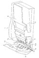
図1は、本実施の形態の原稿搬送装置を取り付けた複写機の外観図である。図1に示すように、本実施の形態の原稿搬送装置1は、複写機本体2の原稿読み取りガラス面3の上部に配置されている。この原稿搬送装置1は、複数の原稿を自動で読み取る際に使用する搬送装置である。
FIG. 1 is an external view of a copying machine to which a document conveying device according to the present embodiment is attached. As shown in FIG. 1, the
また、本実施の形態の原稿搬送装置1は、読み取る原稿を載置する原稿挿入用トレイ4と、原稿挿入用トレイ4の下方に設けられている原稿排出用トレイ5と、上面に設けられた開閉可能な搬送カバー6とを備えている。
The
図2は、本実施の形態の原稿搬送装置1の側面図である。なお、図2では説明のために正面側の外装が取り外されている(図1の正面外装1a参照)。図2に示すように、本実施の形態の原稿搬送装置では、原稿挿入用トレイ4から、その下部に配置された原稿排出用トレイ5へとU字状の原稿搬送路7が形成されている(図中、矢印参照)。このU字状の原稿搬送路7の内側には搬送ユニット8が配置されている。
FIG. 2 is a side view of the
また、U字状の原稿搬送路7が折り返している部分を折り返し湾曲部7aとし、原稿挿入用トレイ4から折り返し湾曲部7aまでの原稿搬送路7を上部搬送路7bとし、折り返し湾曲部7aから原稿排出用トレイ5までの原稿搬送路7を下部搬送路7cとする。
Further, a portion where the U-shaped document conveyance path 7 is folded is a
また、搬送ユニット8には、原稿搬送路7において用紙を搬送するための搬送ローラ10が設けられている。この搬送ローラ10はローラの外周表面が、折り返し湾曲部7aに沿うように配置されている。尚、図2において、搬送ローラ10は、軸10a上に複数個固定配置されており、原稿搬送装置1本体に設けられている駆動手段(図示せず)に接続されている。
Further, the
また、原稿搬送路7中の、原稿読み取りガラス面3近傍の位置を7eとすると、位置7eの直下の複写機本体2には、光学移動枠(ランプとミラー)ユニットが位置づけられている。
If the position near the original
また、原稿挿入用トレイ4には、載置された原稿を原稿搬送路7へ搬送するために、原稿の挿入方向先端側を持ち上げるリフト板22が設けられており、搬送カバー6には給送ローラ12が配置されている。尚、図2では、用紙を持ち上げた状態のリフト板22をリフト板22´として一点鎖線で示している。また、原稿排出用トレイ5へと用紙を排出するために、原稿搬送路7の出口7d近傍の搬送ユニット8に排出ローラ14が設けられている。これら給送ローラ12及び排出ローラ14は図示しない駆動手段に連結されている。なお、搬送カバー6は、支点6aを中心として、搬送ユニット8は、搬送ローラ10の軸10aを中心として、矢印S方向にそれぞれが開閉自在な構成となっている。さらに、搬送ユニット8の上部には、開閉するための把手9が設けられている。なお、開閉する際における、搬送ユニット8の回転外周の位置を8aとする。
The
図3は、本実施の形態の原稿搬送装置1の搬送カバー6を開いた状態の斜視図である。なお、図3においても説明のために正面外装1aは取り外されている。図3では、上部搬送路7bが露出された状態が示されている。また、搬送カバー6の内側に給送ローラ12が配置されている状態が示されている。また、図に示されているように上部搬送路7bから折り返し湾曲部7aにわたって、複数の搬送ローラ10が露出しており、上部搬送路7b及び折り返し湾曲部7aにおける原稿の搬送を担っている。また、搬送カバー6には、複数の搬送ローラ10に対応した、複数のコロ13が配置されている。
FIG. 3 is a perspective view showing a state in which the
図4は、本実施の形態の搬送ユニット8を開いた状態の斜視図である。なお、図4においても説明のために正面外装1aが取り外されている。図4では、下部搬送路7cが露出した状態が示されている。また、上述した排出ローラ14が搬送ユニット8に配置されている状態が図示されている。また、下部搬送路7cにも複数の搬送ローラ10が露出しており、下部搬送路7cにおける用紙の搬送を担っている。なお、下部搬送路7cの下側のガイドには、搬送ローラ10に対応する複数のコロが設けられている。
FIG. 4 is a perspective view showing a state in which the
なお、上記において、搬送ローラ10、給送ローラ12、及び排出ローラ14と、搬送ローラ10に対応するコロ13について説明したが、これら以外にも適宜ローラ及びコロが配置されている。
In the above description, the conveying
次に、本実施の形態の搬送ユニット8に設けられている本発明の開閉機構の一例について説明する。
Next, an example of the opening / closing mechanism of the present invention provided in the
図5は、搬送ユニット8を閉じている状態における搬送ユニット8周辺の拡大図である。図5に示すように、搬送ローラ10が配置されている軸10aを中心として、原稿搬送装置1の筐体に固定されたギア15が設けられている。また、ギア15と連結されている制動力発生手段16が、搬送ユニット8に固定され、設けられている。
FIG. 5 is an enlarged view of the periphery of the
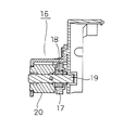
図6は、制動力発生手段16の周辺の拡大図である。図7は、図6のZZ´断面図である。図7に示されているように、制動力発生手段16は、ギア17に圧入されたワンウェイクラッチ18を有している。このワンウェイクラッチ18は、内周側に配置されたベアリングを介して、本発明の支持軸の一例である軸19上に配置されている。更に、軸19上にはトルクリミッタ20も配置されている。このギア17と、上述したギア15が噛み合うように、制動力発生手段16は配置されている。
FIG. 6 is an enlarged view around the braking force generating means 16. FIG. 7 is a ZZ ′ cross-sectional view of FIG. As shown in FIG. 7, the braking force generating means 16 has a one-way clutch 18 that is press-fitted into a
ここで、ワンウェイクラッチ18は、図6において反時計周り(矢印A方向)に回転する際には、内周側のベアリングが回転することにより、軸19に対して自由に回転し、時計回り(矢印B方向)に回転する際には、ベアリングは回転せず、軸19とともに回転する構造になっている。上述したトルクリミッタ20は、軸19の回転に対して制動力を付与する。尚、図5においても、上記矢印A及びBを示している。
Here, when the one-way clutch 18 rotates counterclockwise in FIG. 6 (in the direction of arrow A), the bearing on the inner peripheral side rotates to rotate freely with respect to the
尚、本発明の固定手段の一例は、本実施の形態のギア15に相当し、本発明の開閉機構の一例は、本実施の形態のギア15及び制動力発生手段16に相当する。
An example of the fixing means of the present invention corresponds to the
次に、本実施の形態の原稿搬送装置の動作について説明する。 Next, the operation of the document feeder according to the present embodiment will be described.
上述した原稿搬送装置において、原稿挿入用トレイ4に載置された原稿は、図2の矢印に示すように、上部搬送路7b、及び折り返し湾曲部7aを通過し、位置7eに到達する。この位置7eを原稿が通過するに従って、上述した自動搬送用の原稿読み取り部により、その内容が読み取られる。そして、読み取られた原稿は下部搬送路7cを通過して、原稿排出用トレイ5へと排出される。
In the above-described original conveying apparatus, the original placed on the original inserting
次に、本実施の形態における搬送ユニット8を開閉する動作について説明する。尚、この搬送ユニット8の開閉動作は、上記原稿搬送装置1の原稿搬送動作において、原稿搬送路7中で詰まった原稿を取り除く場合や、メンテナンスの場合に行われる。
Next, an operation for opening and closing the
図8は、搬送ユニット8を開いた状態における搬送ユニット8周辺の拡大図である。
FIG. 8 is an enlarged view of the periphery of the
図5から図8へと、ユーザーが把手9を持ち、搬送ユニット8を開く際には、矢印A方向にギア17が回転する。この矢印A方向への回転の場合、上述したように、ワンウェイクラッチ18は軸19上を自由に回転する。
From FIG. 5 to FIG. 8, when the user holds the
そのため、ユーザーは、トルクリミッタ20による負荷がかけられていない状態で搬送ユニット8を開くことが可能となる(図8中、矢印C参照。)。
Therefore, the user can open the
次に、図8から図5へと搬送ユニット8を閉じる際には、矢印B方向にギア17が回転する。この矢印B方向への回転の場合、ギア17に圧入されているワンウェイクラッチ18と同時に軸19も回転することとなる。この軸19の回転に対して、トルクリミッタ20により制動力が発生する。
Next, when closing the
この制動力の発生により、ギア17が矢印B方向へと回転し難くなるため、制動力発生手段16が取り付けられている搬送ユニット8の矢印D方向への閉じる動作に対して制動力が付与されることになる。
The generation of this braking force makes it difficult for the
このような構成により、搬送ユニット8を開いて、下部搬送路7cで詰まった原稿の除去やメンテナンスを行っている場合であっても、制動力が付与されているので搬送ユニット8は自重によりとじない。そのため、搬送ユニット8を手で支える必要がなくなり、作業効率及び安全性が向上する。
With such a configuration, even when the
また、搬送ユニット8を閉じる際に原稿搬送装置1に対する衝撃を緩和することが可能となる。
Further, the impact on the
ここで、従来の開閉機構のように、仮に搬送ユニット8が開閉する軸10aにトルクリミッタを設けた場合に、搬送ユニット8の自重による落下(閉じる動作)を防止するためには、搬送ユニット8の軸10aから位置8aまでの重量が自重落下する力に対する分の制動力を付与する必要がある。
Here, as in the conventional opening / closing mechanism, if a torque limiter is provided on the
しかしながら、本実施の形態のように搬送ユニット8の、軸10aから位置8aの間に制動力発生手段16を配置することにより、軸10aから位置8aまでの重量が自重落下する力を分散させることが出来るため、従来と比較して小さい制動力を付与するだけで、従来と同等の効果を発揮することが出来る。
However, by disposing the braking force generation means 16 between the
また、本実施の形態における原稿搬送装置1では、ギア15の径を大きくするに従って、付与する必要のある制動力が小さくて済む。そのため、従来では搬送ユニット8の重量に比例して、付与する制動力を大きくする必要があったが、ギアの径を変更することにより付与する必要のある制動力を調整することが可能となる。
In the
また、ギア15の径を大きくすることにより、付与する必要のある制動力を小さくすることが出来るため、トルクリミッタ、ワンウェイクラッチ等の部品の単価が下がり、コストを安くすることが出来る。
Further, since the braking force that needs to be applied can be reduced by increasing the diameter of the
また、本実施の形態における具体例を挙げると、搬送ユニット8の重量が約2kgであり、ギア15の直径が50mm、ギア17の直径が20mmの場合には、トルクリミッタ20に必要な軸トルクは3kgとなる。
As a specific example in the present embodiment, when the weight of the
この具体例のように、本実施の形態ではギア17よりもギア15の直径が大きくなるように構成されている(図5参照)。仮に、ギア15よりもギア17の直径が大きくなるように構成した場合には、ギア17が大きくなることにより、本実施の形態よりも小さい力をかけるだけで搬送ユニット8は閉じられる(自重落下しやすくなる)。一方、ギア15は小さくなるため、搬送ユニット8の自重落下を防止し、その位置を保持するためには、本実施の形態よりも大きい力が必要となる。
As in this specific example, the present embodiment is configured such that the diameter of the
従って、ギア15よりもギア17の直径が大きくなるように構成した場合には、トルクの大きなトルクリミッタを用いることが必要となるため、ギア15の直径が、ギア17よりも大きくなるように構成することが好ましい。
Accordingly, when the
また、仮に、搬送ローラ10の軸10aとは、別に搬送ユニット8の開閉軸を設けた場合には、搬送ユニット8の開閉動作に伴って、搬送ローラ10の位置が移動することになる。このような場合、搬送ローラ10を駆動するための駆動手段が原稿搬送装置1本体に設けられているため、搬送ユニット8を閉じたときに駆動手段と軸10aを連結するための連結機構が必要となる。このような連結機構を設けた場合には、連結不良が発生するおそれがあった。
If the opening / closing shaft of the
しかしながら、本実施の形態における原稿搬送装置1では、搬送ローラ10の軸10aが、搬送ユニット8の開閉軸と一致しているため、搬送ユニット8の開閉動作を行った場合であっても、搬送ローラ10の位置は移動しない。そのため、本実施の形態の原稿搬送装置では、搬送ローラ10を回転させるために本体装置側に設けられている駆動手段と直結することが出来、連結機構を用いる必要がないために上記連結不良は発生しない。
However, in the
尚、上記実施の形態において、原稿搬送装置1に設けられた開閉自在の搬送ユニット8を、本発明の開閉部材の一例として用いて、本発明の開閉機構について説明したが、本発明の開閉機構は、原稿搬送装置に限らず適用可能である。要するに、開閉自在な開閉部材が設けられた装置に対して適用可能である。更に、本発明の開閉部材の一例としてドアや窓に対しても、本発明の開閉機構を適用することが可能であり、手や指が挟まれることを防止することが出来る。
In the above embodiment, the openable /
又、本実施の形態では、本発明の固定手段の一例であるギア15は、制動力発生手段16のギア17と、それらの外周縁部の歯車形状によって噛み合っているが、本構成に限らず、例えば、固定手段と制動力発生手段がベルトによって連結されていてもよい。尚、ベルトによって連結している場合には、固定手段及び制動力発生手段ともに歯車形状を有していなくてもよい。
In the present embodiment, the
本発明の開閉機構は、従来よりも小さい制動力により、自重により閉じることを防止することが可能な、または、装置本体への衝撃を緩和することが可能な効果を有し、原稿搬送装置の搬送ユニット等として有用である。 The opening / closing mechanism of the present invention has an effect of being able to prevent closing due to its own weight with a braking force smaller than that of the conventional one or to reduce an impact on the apparatus main body. It is useful as a transport unit.
1 原稿搬送装置
2 複写機
3 原稿読み取りガラス
4 原稿挿入用トレイ
5 原稿排出用トレイ
6 搬送カバー
7 原稿搬送路
8 搬送ユニット
9 把手
10 搬送ローラ
12 給送ローラ
13 コロ
14 排出ローラ
15 ギア
16 制動力発生手段
17 ギア
18 ワンウェイクラッチ
19 軸
20 トルクリミッタ
DESCRIPTION OF
Claims (5)
前記制動力発生手段と連結され、前記本体装置に固定された固定手段と、を備え、
前記制動力発生手段は、前記閉じる動作にともなう前記固定手段との間の相対的な動作に対して前記制動力を発生する、開閉機構。 A braking force generating means for generating a braking force for braking at least the closing operation of the opening / closing operation centered on the opening / closing axis of the opening / closing member, provided on an opening / closing member that is openable / closable with respect to the main body device;
A fixing means connected to the braking force generating means and fixed to the main body device,
The opening / closing mechanism, wherein the braking force generating unit generates the braking force with respect to a relative operation with the fixing unit accompanying the closing operation.
外周縁部が歯車形状であるワンウェイクラッチと、
トルクリミッタと、
前記ワンウェイクラッチ及び前記トルクリミッタが設けられた支持軸と、を有し、
前記固定手段の外周縁部は、前記ワンウェイクラッチの歯車形状と噛み合う歯車形状である、請求項2記載の開閉機構。 The braking force generating means is
A one-way clutch whose outer peripheral edge is gear-shaped,
A torque limiter,
A support shaft provided with the one-way clutch and the torque limiter,
The opening / closing mechanism according to claim 2, wherein an outer peripheral edge portion of the fixing means has a gear shape that meshes with a gear shape of the one-way clutch.
前記原稿挿入用トレイの下方向に設けられた原稿排出用トレイと、
前記原稿挿入用トレイから前記原稿排出用トレイへと前記原稿を搬送するための搬送ユニットと、
請求項1記載の開閉機構と、を備え、
前記搬送ユニットは、前記開閉部材である、原稿搬送装置。 A document insertion tray to be placed for conveying a document;
A document discharge tray provided below the document insertion tray;
A transport unit for transporting the document from the document insertion tray to the document discharge tray;
An opening and closing mechanism according to claim 1,
The document transport device, wherein the transport unit is the opening / closing member.
前記搬送ローラの回転軸は、前記開閉軸と一致している、請求項4記載の原稿搬送装置。 The transport unit has a transport roller for transporting the document,
The document conveying apparatus according to claim 4, wherein a rotation axis of the conveying roller coincides with the opening / closing axis.
Priority Applications (1)
| Application Number | Priority Date | Filing Date | Title |
|---|---|---|---|
| JP2005338847A JP2007147739A (en) | 2005-11-24 | 2005-11-24 | Opening/closing mechanism and document conveyance device |
Applications Claiming Priority (1)
| Application Number | Priority Date | Filing Date | Title |
|---|---|---|---|
| JP2005338847A JP2007147739A (en) | 2005-11-24 | 2005-11-24 | Opening/closing mechanism and document conveyance device |
Publications (1)
| Publication Number | Publication Date |
|---|---|
| JP2007147739A true JP2007147739A (en) | 2007-06-14 |
Family
ID=38209251
Family Applications (1)
| Application Number | Title | Priority Date | Filing Date |
|---|---|---|---|
| JP2005338847A Pending JP2007147739A (en) | 2005-11-24 | 2005-11-24 | Opening/closing mechanism and document conveyance device |
Country Status (1)
| Country | Link |
|---|---|
| JP (1) | JP2007147739A (en) |
Cited By (1)
| Publication number | Priority date | Publication date | Assignee | Title |
|---|---|---|---|---|
| JP2010041561A (en) * | 2008-08-07 | 2010-02-18 | Murata Machinery Ltd | Automatic document feeder and draft reading device equipped with the same |
Citations (4)
| Publication number | Priority date | Publication date | Assignee | Title |
|---|---|---|---|---|
| JPH0475073A (en) * | 1990-07-17 | 1992-03-10 | Ricoh Co Ltd | Developing device |
| JPH0475074A (en) * | 1990-07-18 | 1992-03-10 | Seiko Epson Corp | Developing device |
| JPH04143771A (en) * | 1990-10-05 | 1992-05-18 | Ricoh Co Ltd | Electrophotographic image formation device |
| JPH06343123A (en) * | 1993-06-01 | 1994-12-13 | Hitachi Ltd | Image reader and facsimile equipment |
-
2005
- 2005-11-24 JP JP2005338847A patent/JP2007147739A/en active Pending
Patent Citations (4)
| Publication number | Priority date | Publication date | Assignee | Title |
|---|---|---|---|---|
| JPH0475073A (en) * | 1990-07-17 | 1992-03-10 | Ricoh Co Ltd | Developing device |
| JPH0475074A (en) * | 1990-07-18 | 1992-03-10 | Seiko Epson Corp | Developing device |
| JPH04143771A (en) * | 1990-10-05 | 1992-05-18 | Ricoh Co Ltd | Electrophotographic image formation device |
| JPH06343123A (en) * | 1993-06-01 | 1994-12-13 | Hitachi Ltd | Image reader and facsimile equipment |
Cited By (1)
| Publication number | Priority date | Publication date | Assignee | Title |
|---|---|---|---|---|
| JP2010041561A (en) * | 2008-08-07 | 2010-02-18 | Murata Machinery Ltd | Automatic document feeder and draft reading device equipped with the same |
Similar Documents
| Publication | Publication Date | Title |
|---|---|---|
| US7245855B2 (en) | Opening and closing device, sheet conveying apparatus, and image forming apparatus | |
| JP4785574B2 (en) | Image forming apparatus and opening / closing mechanism | |
| JP2008216287A (en) | Image forming apparatus | |
| JP4923683B2 (en) | Opening / closing mechanism of opening / closing part, image forming apparatus | |
| JP4584811B2 (en) | Manual feed device, manual feed device, and image forming apparatus | |
| JP2005225602A (en) | Recording medium supply device, and image forming device | |
| JP2007147739A (en) | Opening/closing mechanism and document conveyance device | |
| JP2006083551A (en) | Cover opening/closing mechanism and image forming device equipped with the cover opening/closing device | |
| JP2007293017A (en) | Image forming apparatus | |
| JP6210899B2 (en) | Gear engagement mechanism and image forming apparatus | |
| KR101430017B1 (en) | Auto document feeding apparatus and document reading device including the same | |
| JP5146157B2 (en) | Image forming apparatus | |
| JP2006089165A (en) | Upper cover, sheet carrier and image forming device | |
| JP2010045695A (en) | Image reading apparatus | |
| JP2011042416A (en) | Paper feeder and image forming device using the same | |
| JP3948457B2 (en) | Automatic document feeder | |
| JP4508933B2 (en) | Sheet conveying apparatus, sheet processing apparatus, and image forming apparatus | |
| JP2007261698A (en) | Sheet conveying device and image reading device provided therewith | |
| JP5216548B2 (en) | Sheet conveying apparatus and image reading apparatus | |
| JP5146914B2 (en) | Automatic document feeder and document reader having the same | |
| JP4205251B2 (en) | Image forming apparatus | |
| JP4076576B2 (en) | Automatic document feeder | |
| JP4544621B2 (en) | Image forming apparatus | |
| JP2010030750A (en) | Opening/closing cover and image forming device equipped therewith | |
| JP4618518B2 (en) | Document reader |
Legal Events
| Date | Code | Title | Description |
|---|---|---|---|
| A621 | Written request for application examination |
Free format text: JAPANESE INTERMEDIATE CODE: A621 Effective date: 20081027 |
|
| A977 | Report on retrieval |
Free format text: JAPANESE INTERMEDIATE CODE: A971007 Effective date: 20110427 |
|
| A131 | Notification of reasons for refusal |
Free format text: JAPANESE INTERMEDIATE CODE: A131 Effective date: 20110510 |
|
| A02 | Decision of refusal |
Free format text: JAPANESE INTERMEDIATE CODE: A02 Effective date: 20110913 |