JP2007146715A - Turbocharger and fluid device for turbocharger - Google Patents

Turbocharger and fluid device for turbocharger Download PDF

Info

Publication number
JP2007146715A
JP2007146715A JP2005340482A JP2005340482A JP2007146715A JP 2007146715 A JP2007146715 A JP 2007146715A JP 2005340482 A JP2005340482 A JP 2005340482A JP 2005340482 A JP2005340482 A JP 2005340482A JP 2007146715 A JP2007146715 A JP 2007146715A
Authority
JP
Japan
Prior art keywords
housing
turbocharger
compressor
turbine
fluid device
Prior art date
Legal status (The legal status is an assumption and is not a legal conclusion. Google has not performed a legal analysis and makes no representation as to the accuracy of the status listed.)
Pending
Application number
JP2005340482A
Other languages
Japanese (ja)
Inventor
Wataru Akai
亘 赤井
Current Assignee (The listed assignees may be inaccurate. Google has not performed a legal analysis and makes no representation or warranty as to the accuracy of the list.)
Toyota Motor Corp
Original Assignee
Toyota Motor Corp
Priority date (The priority date is an assumption and is not a legal conclusion. Google has not performed a legal analysis and makes no representation as to the accuracy of the date listed.)
Filing date
Publication date
Application filed by Toyota Motor Corp filed Critical Toyota Motor Corp
Priority to JP2005340482A priority Critical patent/JP2007146715A/en
Publication of JP2007146715A publication Critical patent/JP2007146715A/en
Pending legal-status Critical Current

Links

Images

Abstract

<P>PROBLEM TO BE SOLVED: To provide a low cost fluid device for a turbocharger. <P>SOLUTION: The fluid device for the turbocharger includes wheels 32, 34 acting on fluid and housings 14, 24 surrounding an outer circumference of the wheels 32, 34 and constructing a flow path of fluid. Spaces 40, 50 in the housings 14, 24 share an axis L with the wheels 32, 34 and has a rotationally symmetric shape in relation to the axis L. A low cost turbocharger 10 can be provided by including the fluid devices for the turbocharger on a turbine 16 side and a compressor 12 side, respectively. <P>COPYRIGHT: (C)2007,JPO&INPIT

Description

本発明は、流体に作用するホイールと、このホイールの外周を囲みその流体の流路を構成するハウジングと、を有するターボチャージャ用流体装置、およびこのターボチャージャ用流体装置を有するターボチャージャに関する。   The present invention relates to a turbocharger fluid device having a wheel that acts on a fluid and a housing that surrounds the outer periphery of the wheel and forms a flow path for the fluid, and a turbocharger having the turbocharger fluid device.

ターボチャージャはタービンやコンプレッサを有し、一般的なそのハウジングは、タービンホイールが収容されるタービンハウジングと、コンプレッサインペラが収容されるコンプレッサハウジングと、これらタービンホイールとコンプレッサインペラとを連結するロータシャフトが回転可能に支持されるセンタハウジングとから概ね構成されている(例えば、特許文献1参照)。このようなタービンハウジングにおける渦巻状の流路の断面積は、それに収容されるタービンホイールを介して排気ガスから効率よくエネルギが取り出されるように、タービンホイールに向けて漸次縮小するように設計されている。また同様にコンプレッサハウジングにおける渦巻状の流路の断面積は、それに収容されるコンプレッサインペラによって吸入した空気に適切にエネルギを与えるように、コンプレッサインペラから離れるにしたがい漸次拡大するように設計されている。なお、このようなターボチャージャのハウジングは、概ね鋳造により作製されている。   A turbocharger has a turbine and a compressor, and a general housing thereof includes a turbine housing in which a turbine wheel is accommodated, a compressor housing in which a compressor impeller is accommodated, and a rotor shaft that connects the turbine wheel and the compressor impeller. It is generally composed of a center housing that is rotatably supported (see, for example, Patent Document 1). The cross-sectional area of the spiral channel in such a turbine housing is designed to gradually shrink towards the turbine wheel so that energy is efficiently extracted from the exhaust gas through the turbine wheel housed in it. Yes. Similarly, the cross-sectional area of the spiral flow path in the compressor housing is designed to gradually expand as it moves away from the compressor impeller so as to properly energize the air drawn in by the compressor impeller accommodated therein. . Such a turbocharger housing is generally manufactured by casting.

特開2003−97281号公報JP 2003-97281 A

ところで、全てのターボチャージャが必ずしも優れた性能を有する必要はなく、適応される車両によっては、優れた性能よりも、安価である方が望まれる場合もある。   By the way, it is not always necessary that all turbochargers have excellent performance, and depending on the vehicle to which the turbocharger is applied, it may be desired that it is cheaper than excellent performance.

そこで、本発明は、安価なターボチャージャを提供するために用いられるターボチャージャ用流体装置を提供することを目的とする。さらに、本発明は、これにより安価に作製されるターボチャージャを提供することを目的とする。   Therefore, an object of the present invention is to provide a turbocharger fluid device used for providing an inexpensive turbocharger. Furthermore, an object of the present invention is to provide a turbocharger manufactured at a low cost.

上記目的を達成するために、本発明に係るターボチャージャ用流体装置は、流体に作用するホイールと、該ホイールの外周を囲み前記流体の流路を構成するハウジングと、を有するターボチャージャ用流体装置であって、前記ハウジング内の空間は、前記ホイールと軸心を共通にし、且つ前記軸心に関して回転対称形であることを特徴とする。   To achieve the above object, a turbocharger fluid device according to the present invention comprises a wheel that acts on the fluid, and a housing that surrounds the outer periphery of the wheel and forms a flow path for the fluid. The space in the housing has a common axis with the wheel and is rotationally symmetric with respect to the axis.

上記構成により、ハウジング内の空間が回転対称形なので、その設計および製作を容易にすることが出来、ターボチャージャ用流体装置を安価に作製することが可能になる。したがって、これを用いて安価なターボチャージャを提供することが可能になる。   With the above configuration, since the space in the housing is rotationally symmetric, the design and manufacture can be facilitated, and the turbocharger fluid device can be manufactured at low cost. Therefore, an inexpensive turbocharger can be provided using this.

前記ハウジング内の空間の径方向断面形状が矩形であるとなお好ましい。これにより、ハウジングを設置した場合の周囲のデッドスペースを抑制することが可能になる。   More preferably, the radial cross-sectional shape of the space in the housing is rectangular. Thereby, it becomes possible to suppress the surrounding dead space when the housing is installed.

特に、前記ハウジングは、前記ホイールの径方向外側に隣接するハウジング本体と、前記ホイールに軸方向に隣接するシュラウド部材と、を有し、前記ハウジング本体と前記シュラウド部材とが結合されたものであると好ましい。これにより、そのハウジングは、より安価に且つ容易に作製することが可能な部位に分けられ、これらを結合することで安価にハウジングを作製することが可能になる。   In particular, the housing has a housing main body adjacent to the outer side in the radial direction of the wheel, and a shroud member adjacent to the wheel in the axial direction, and the housing main body and the shroud member are combined. And preferred. As a result, the housing is divided into parts that can be manufactured more inexpensively and easily, and by combining them, the housing can be manufactured at low cost.

この場合、前記ハウジング本体および前記シュラウド部材の少なくとも一方は、塑性加工によって製造されると良い。すなわち、既存の種々の板材や管材などを塑性加工することで、前記ハウジング本体および前記シュラウド部材の少なくとも一方を作製することが可能になる。したがって、より安価にハウジングを作製することが可能になる。   In this case, at least one of the housing body and the shroud member may be manufactured by plastic working. That is, it becomes possible to produce at least one of the housing body and the shroud member by plastically processing various existing plate materials and pipe materials. Therefore, the housing can be manufactured at a lower cost.

また、前記ハウジング内の空間には、該ハウジングの流路外端部の接線方向に前記流体を向ける仕切部を有すると良い。これにより、ハウジングの流路外端部の接線方向に流体が方向付けられる。   The space in the housing may include a partition portion for directing the fluid in a tangential direction of an outer end portion of the flow path of the housing. Thereby, the fluid is directed in the tangential direction of the flow path outer end portion of the housing.

これら上記した様々な態様のターボチャージャ用流体装置をタービン側およびコンプレッサ側にそれぞれ有することを特徴とするターボチャージャが提供されるのが好ましい。このターボチャージャは、上記の如く安価なターボチャージャ用流体装置をタービン側およびコンプレッサ側の両方に有するので、全体として安価に作製される。   It is preferable to provide a turbocharger having the above-described various turbocharger fluid devices on the turbine side and the compressor side. Since the turbocharger has the inexpensive turbocharger fluid device on both the turbine side and the compressor side as described above, the turbocharger is manufactured at a low cost as a whole.

以下、本発明に係る好適な実施形態を、添付図面を参照して説明する。
まず、本発明に係るターボチャージャ用流体装置およびこれを用いたターボチャージャを、第一実施形態に基づいて説明する。図1は、本第一実施形態のターボチャージャ10を概略的に示していて、図1(a)はターボチャージャ10の断面側面図であり、図1(b)は図1(a)のターボチャージャ10のコンプレッサ12のコンプレッサハウジング14の側面図である。また、図2は、図1(b)のコンプレッサハウジング14の、図1(a)のA−A線に沿った概略的な断面図である。さらに、図3は、図1および図2のコンプレッサハウジング14の概略的な分解斜視図である。なお、ターボチャージャ10は、コンプレッサ12およびタービン16を備えている。
DESCRIPTION OF EXEMPLARY EMBODIMENTS Hereinafter, preferred embodiments according to the invention will be described with reference to the accompanying drawings.
First, a turbocharger fluid device according to the present invention and a turbocharger using the same will be described based on a first embodiment. FIG. 1 schematically shows a turbocharger 10 according to the first embodiment. FIG. 1A is a sectional side view of the turbocharger 10, and FIG. 1B is a turbo view of FIG. 2 is a side view of the compressor housing 14 of the compressor 12 of the charger 10. FIG. FIG. 2 is a schematic cross-sectional view of the compressor housing 14 of FIG. 1 (b) along the line AA of FIG. 1 (a). Further, FIG. 3 is a schematic exploded perspective view of the compressor housing 14 of FIGS. 1 and 2. The turbocharger 10 includes a compressor 12 and a turbine 16.

図1(a)に示すように、ターボチャージャ10は、ハウジング18およびターボロータ20を備えている。ハウジング18は、センタハウジング22、タービンハウジング24およびコンプレッサハウジング14からなる。センタハウジング22およびタービンハウジング24によってタービン室26が形成され、センタハウジング22およびコンプレッサハウジング14によってコンプレッサ室28が形成されている。   As shown in FIG. 1A, the turbocharger 10 includes a housing 18 and a turbo rotor 20. The housing 18 includes a center housing 22, a turbine housing 24 and a compressor housing 14. A turbine chamber 26 is formed by the center housing 22 and the turbine housing 24, and a compressor chamber 28 is formed by the center housing 22 and the compressor housing 14.

ターボロータ20はロータシャフト30を備え、その一端にタービンホイール32が固定され、他端にコンプレッサインペラ34が固定されている。ロータシャフト30は、センタハウジング22に設けられた一対の軸受36によって回転可能に支持されている。タービンホイール32は複数の羽根32aを備え、タービン室26に配置されている。コンプレッサインペラ34は複数の羽根34aを備え、コンプレッサ室28に配置されている。   The turbo rotor 20 includes a rotor shaft 30, a turbine wheel 32 is fixed to one end thereof, and a compressor impeller 34 is fixed to the other end. The rotor shaft 30 is rotatably supported by a pair of bearings 36 provided in the center housing 22. The turbine wheel 32 includes a plurality of blades 32 a and is disposed in the turbine chamber 26. The compressor impeller 34 includes a plurality of blades 34 a and is disposed in the compressor chamber 28.

タービンハウジング24には、排気入口38と、排気環状通路40と、排気導入通路42と、そして排気出口44とが設けられている。排気環状通路40は、タービン室26の外周に沿ってほぼ環状に形成され、その導入側の排気入口38には図示しないエンジンの排気管が接続されている。排気導入通路42は、タービン室26の周囲と排気環状通路40とを連通させる。排気出口44はタービン室26の軸心(軸線)Lの方向に延びるように形成され、図示しない排気管に接続されている。そして、エンジンが運転されて排気管から排気環状通路40に導入された排気ガスは、排気環状通路40に沿ってタービン室26の周囲を移動しながら排気導入通路42からタービン室26内に導入される。そして、タービンホイール32を回転させて、排気ガスは、タービン室26内で直角に向きを変えて、排気出口44から排気管に排出される。なお、排気環状通路40も排気導入通路42も共に、ほぼ環状であり、タービンホイール32の軸心Lに関して回転対称形である。   The turbine housing 24 is provided with an exhaust inlet 38, an exhaust annular passage 40, an exhaust introduction passage 42, and an exhaust outlet 44. The exhaust annular passage 40 is formed in a substantially annular shape along the outer periphery of the turbine chamber 26, and an exhaust pipe of an engine (not shown) is connected to the exhaust inlet 38 on the introduction side. The exhaust introduction passage 42 communicates the periphery of the turbine chamber 26 with the exhaust annular passage 40. The exhaust outlet 44 is formed to extend in the direction of the axis (axis) L of the turbine chamber 26 and is connected to an exhaust pipe (not shown). Then, the exhaust gas introduced into the exhaust annular passage 40 from the exhaust pipe when the engine is operated is introduced into the turbine chamber 26 from the exhaust introduction passage 42 while moving around the turbine chamber 26 along the exhaust annular passage 40. The Then, by rotating the turbine wheel 32, the exhaust gas changes its direction at right angles in the turbine chamber 26 and is discharged from the exhaust outlet 44 to the exhaust pipe. Both the exhaust annular passage 40 and the exhaust introduction passage 42 are substantially annular and are rotationally symmetric with respect to the axis L of the turbine wheel 32.

一方、上記コンプレッサハウジング14には、吸気入口46と、吸気導出通路48と、吸気環状通路50と、そして吸気出口52が設けられている。吸気入口46はコンプレッサ室28の軸心Lの方向に延びるように形成されていて、そこに接続される図示しない吸気管の端部が図示しないエアクリーナ等を介して、大気に開口されている。吸気環状通路50は、コンプレッサ室28の外周に沿ってほぼ環状に形成され、その供給出口である吸気出口52は図示しない吸気管に接続されている。吸気導出通路48は、コンプレッサ室28の周囲と吸気環状通路50とを連通させる。そして、上記タービン室26に導入される排気ガスによってターボロータ20が回転すると、コンプレッサインペラ34が回転してコンプレッサ室28から外気を吸気導出通路48を通じて吸気環状通路50に圧送し、吸気入口46を通じて新たな外気をコンプレッサ室28に導入する。なお、吸気導出通路48も吸気環状通路50も共に、ほぼ環状であり、タービンホイール32の軸心Lに一致するコンプレッサホイール34の軸心Lに関して回転対称形である。   On the other hand, the compressor housing 14 is provided with an intake inlet 46, an intake outlet passage 48, an intake annular passage 50, and an intake outlet 52. The intake inlet 46 is formed so as to extend in the direction of the axis L of the compressor chamber 28, and an end portion of an intake pipe (not shown) connected thereto is opened to the atmosphere via an air cleaner or the like (not shown). The intake annular passage 50 is formed in a substantially annular shape along the outer periphery of the compressor chamber 28, and an intake outlet 52 serving as a supply outlet thereof is connected to an intake pipe (not shown). The intake lead-out passage 48 communicates the periphery of the compressor chamber 28 with the intake annular passage 50. Then, when the turbo rotor 20 is rotated by the exhaust gas introduced into the turbine chamber 26, the compressor impeller 34 rotates to pump outside air from the compressor chamber 28 to the intake annular passage 50 through the intake outlet passage 48 and through the intake inlet 46. New outside air is introduced into the compressor chamber 28. Note that both the intake outlet passage 48 and the intake annular passage 50 are substantially annular and are rotationally symmetric with respect to the axis L of the compressor wheel 34 that coincides with the axis L of the turbine wheel 32.

上記の如く、ターボチャージャ10のタービン16側およびコンプレッサ12側には、それぞれ本発明の実施形態のターボチャージャ用流体装置が備えられている。すなわち、ターボチャージャ10の一端側には、排気ガスに作用するタービンホイール32と、このタービンホイール32の外周を囲み排気ガスの流路を構成するタービンハウジング24と、を有するターボチャージャ用流体装置であるタービン16が備えられている。これと反対側のターボチャージャ10の他端側には、空気に作用するコンプレッサホイールとも称され得るコンプレッサインペラ34と、このコンプレッサインペラ34の外周を囲み空気の流路を構成するコンプレッサハウジング14と、を有するターボチャージャ用流体装置であるコンプレッサ12が備えられている。   As described above, the turbocharger fluid device according to the embodiment of the present invention is provided on the turbine 16 side and the compressor 12 side of the turbocharger 10, respectively. That is, a turbocharger fluid device having a turbine wheel 32 that acts on exhaust gas and a turbine housing 24 that surrounds the outer periphery of the turbine wheel 32 and forms a flow path of exhaust gas is provided at one end of the turbocharger 10. A turbine 16 is provided. On the other side of the turbocharger 10 on the opposite side, a compressor impeller 34 that can also be referred to as a compressor wheel that acts on air, a compressor housing 14 that surrounds the outer periphery of the compressor impeller 34 and forms an air flow path, A compressor 12 which is a fluid device for a turbocharger having the above is provided.

タービンハウジング24とコンプレッサハウジング14とは、上述の如く用途は異なるが、概ね同じ構成を有している。まず、コンプレッサハウジング14について説明する。   Although the turbine housing 24 and the compressor housing 14 have different uses as described above, they have substantially the same configuration. First, the compressor housing 14 will be described.

コンプレッサハウジング14は、コンプレッサインペラ34の径方向外側に隣接するハウジング本体54と、コンプレッサインペラ34に軸方向に隣接するシュラウド部材56と、を有し、ハウジング本体54とシュラウド部材56とが結合されたものである。なお、ハウジング本体54は、鋳造製であり、リング状部58と、延出部60とが予め一体とされて作製されている。また、シュラウド部材56も、同じく、鋳造製である。   The compressor housing 14 includes a housing main body 54 adjacent to the radially outer side of the compressor impeller 34 and a shroud member 56 adjacent to the compressor impeller 34 in the axial direction, and the housing main body 54 and the shroud member 56 are coupled to each other. Is. The housing main body 54 is made of a casting, and the ring-shaped portion 58 and the extending portion 60 are integrally formed in advance. The shroud member 56 is also made of cast material.

ハウジング本体54のリング状部58は、内部に収容されるコンプレッサインペラ34と共通の軸心Lを有し、概ねその軸心Lに関して回転対称形を有している。そして、そのリング状部58により、その中に区画形成される上記吸気環状通路50は、コンプレッサインペラ34と共通の軸心Lを有し、且つその軸心Lに関して回転対称形を有している。それ故、図2において、リング状部58の周壁部62上の点であり、軸心Lと直交する同一断面上の任意の点αおよびβまでの、軸心Lからの距離は、同一である。また、図1(a)にて明瞭に示されているように、リング状部58により区画形成される、コンプレッサハウジング14内の吸気環状通路50の径方向断面形状は概ね矩形であり、リング状部58は、ほぼ円筒形の形状を有している。そして、吸気環状通路50の径方向内側には、上記の如く吸気導出通路48が全周に亘って形成されていて、その吸気導出通路48は吸気環状通路50の軸心Lの方向の幅よりも、かなり狭い幅を有している。   The ring-shaped portion 58 of the housing main body 54 has a common shaft center L with the compressor impeller 34 accommodated therein, and has a rotationally symmetrical shape with respect to the shaft center L. The intake annular passage 50 defined therein by the ring-shaped portion 58 has a common shaft center L with the compressor impeller 34 and has a rotationally symmetrical shape with respect to the shaft center L. . Therefore, in FIG. 2, the distances from the axis L to the points α and β on the same cross section orthogonal to the axis L are the same on the peripheral wall 62 of the ring-shaped part 58. is there. Further, as clearly shown in FIG. 1 (a), the radial cross-sectional shape of the intake annular passage 50 in the compressor housing 14 that is defined by the ring-shaped portion 58 is generally rectangular. The part 58 has a substantially cylindrical shape. The intake lead-out passage 48 is formed on the inner side in the radial direction of the intake annular passage 50 as described above, and the intake lead-out passage 48 is larger than the width of the intake annular passage 50 in the direction of the axis L. Also have a fairly narrow width.

リング状部58から延出した延出部60は、リング状部58から最も離れた端部に出口側フランジ部64を備え、その他の部分は概ね円筒形とされている。延出部60は、リング状部58の最外周部に、その接線方向に沿って連通しているので、吸気環状通路50を流れる空気は、吸気環状通路50の流路外端部の接線方向に概ね流れて、延出部60により区画形成される吸気出口52に至ることになる。なお、延出部60の基部、すなわちリング状部58とのその連通部66は、その断面が矩形とされていても良い。   The extended portion 60 extending from the ring-shaped portion 58 includes an outlet side flange portion 64 at the end farthest from the ring-shaped portion 58, and the other portion is generally cylindrical. Since the extending portion 60 communicates with the outermost peripheral portion of the ring-shaped portion 58 along the tangential direction, the air flowing through the intake annular passage 50 is tangential to the flow path outer end portion of the intake annular passage 50. To the intake outlet 52 that is defined by the extending portion 60. In addition, the base part of the extension part 60, that is, the communication part 66 with the ring-shaped part 58, may have a rectangular cross section.

なお、リング状部58の放射方向における最も内側には、内向きに突出するフランジ部68(図3参照)が設けられており、このフランジ部68の内径はコンプレッサインペラ34の外径よりもわずかに大きくされ、これによって組立の際にフランジ部68の内側をコンプレッサインペラ34が通過することが可能にされている。   An inwardly projecting flange portion 68 (see FIG. 3) is provided on the innermost side in the radial direction of the ring-shaped portion 58, and the inner diameter of the flange portion 68 is slightly smaller than the outer diameter of the compressor impeller 34. This allows the compressor impeller 34 to pass inside the flange portion 68 during assembly.

上記シュラウド部材56が、コンプレッサ12への空気の入口を区画形成するべく、コンプレッサ12に備えられている。シュラウド部材56は、入口側フランジ部70と、リング状部58との接合部を形成する接合フランジ部72と、リング状部58内に収容される筒状部74とを有している。筒状部74は、コンプレッサインペラ34の羽根34aのシュラウド部と称される曲状端縁34bの回転経路輪郭に倣った形状を径方向内側の側面に有している。なお、本明細書において、羽根34aにおける最外周の軸方向に延びる直状端縁34cと、軸端側の放射方向に延びる直状端縁34dとの間の羽根34aの曲状端縁34bが、シュラウド部と称される。   The shroud member 56 is provided in the compressor 12 to define an air inlet to the compressor 12. The shroud member 56 includes an inlet flange portion 70, a joint flange portion 72 that forms a joint portion with the ring-shaped portion 58, and a cylindrical portion 74 that is accommodated in the ring-shaped portion 58. The cylindrical portion 74 has a shape that follows the rotational path contour of the curved end edge 34 b called the shroud portion of the blade 34 a of the compressor impeller 34 on the radially inner side surface. In the present specification, the curved edge 34b of the blade 34a between the straight edge 34c extending in the axial direction of the outermost periphery of the blade 34a and the straight edge 34d extending in the radial direction on the shaft end side , Referred to as the shroud section.

ここで、ターボチャージャ用流体装置であるコンプレッサ12の組立順序を、以下に記す。
(1)第一に、ロータシャフト30の一端部に、センタハウジング22の一端部に位置するコンプレッサ側プレート部76を背にして、コンプレッサインペラ34が取り付けられる。
(2)第二に、リング状部58と延出部60とからなるハウジング本体54が、コンプレッサインペラ34の径方向外側に隣接するように、軸心Lの方向に移動されて、コンプレッサ側プレート部76にボルトナットCB1で結合される。
(3)第三に、シュラウド部材56が、コンプレッサインペラ34に軸心Lの方向に隣接するように、軸心Lの方向に移動されて、ハウジング本体54にボルトナットCB2で結合される。
Here, the assembly order of the compressor 12 that is a fluid device for a turbocharger will be described below.
(1) First, the compressor impeller 34 is attached to one end portion of the rotor shaft 30 with the compressor side plate portion 76 located at one end portion of the center housing 22 in the back.
(2) Secondly, the housing main body 54 composed of the ring-shaped portion 58 and the extending portion 60 is moved in the direction of the axis L so as to be adjacent to the radially outer side of the compressor impeller 34, and the compressor side plate It is connected to the portion 76 with a bolt and nut CB1.
(3) Third, the shroud member 56 is moved in the direction of the shaft center L so as to be adjacent to the compressor impeller 34 in the direction of the shaft center L, and is coupled to the housing main body 54 by the bolt nut CB2.

この工程を経ることで、コンプレッサ12が組み立てられる。なお、上記(1)および(2)の順番は、逆であっても良い。   Through this process, the compressor 12 is assembled. Note that the order of (1) and (2) above may be reversed.

次に、タービン16の構成等を以下に記す。
タービンハウジング24は、タービンホイール32の径方向外側に隣接するハウジング本体80と、タービンホイール32に軸方向に隣接するシュラウド部材82と、を有し、ハウジング本体80とシュラウド部材82とが結合されたものである。なお、タービンハウジング24のハウジング本体80は、コンプレッサハウジング14のハウジング本体54と同様に、リング状部84と、延出部86とが予め一体とされて作製されている。
Next, the configuration of the turbine 16 will be described below.
The turbine housing 24 includes a housing main body 80 adjacent to the radially outer side of the turbine wheel 32 and a shroud member 82 adjacent to the turbine wheel 32 in the axial direction, and the housing main body 80 and the shroud member 82 are coupled to each other. Is. In addition, the housing main body 80 of the turbine housing 24 is produced by previously integrating the ring-shaped portion 84 and the extending portion 86 in the same manner as the housing main body 54 of the compressor housing 14.

ハウジング本体80は、鋳造製であり、そのリング状部84は、内部に収容されるタービンホイール32と共通の軸心Lを有し、概ねその軸心Lに関して回転対称形を有している。そして、そのリング状部84により区画形成される空間である上記排気環状通路40は、タービンインペラ32と軸心Lを共通にし、且つその軸心Lに関して回転対称形を有するようにされている。また、リング状部84により区画形成される、タービンハウジング24内の空間である排気環状通路40の径方向断面形状は概ね矩形であり、リング状部84は、軸心Lの方向にほぼ円筒形の形状を有している。そして、排気環状通路40の径方向内側には、排気導出通路42が全周に亘って形成されていて、その排気導出通路42は排気環状通路40の軸心Lの方向の幅よりも、かなり狭い幅を有している。   The housing main body 80 is made of cast, and the ring-shaped portion 84 has a common axis L with the turbine wheel 32 accommodated therein, and has a rotationally symmetric shape with respect to the axis L. The exhaust annular passage 40, which is a space defined by the ring-shaped portion 84, has the turbine impeller 32 and the shaft center L in common and has a rotationally symmetric shape with respect to the shaft center L. The exhaust annular passage 40, which is a space in the turbine housing 24 and defined by the ring-shaped portion 84, has a generally rectangular cross-sectional shape in the radial direction, and the ring-shaped portion 84 is substantially cylindrical in the direction of the axis L. It has the shape of An exhaust outlet passage 42 is formed on the inner side in the radial direction of the exhaust annular passage 40 over the entire circumference. The exhaust outlet passage 42 is considerably larger than the width of the exhaust annular passage 40 in the direction of the axis L. It has a narrow width.

一方、リング状部84から延出した延出部86は、リング状部84から最も離れた端部に入口側フランジ部88を備え、その他の部分は概ね円筒形とされている。延出部86は、リング状部84の最外周部の接線方向に沿って連通しているので、排気環状通路40を流れる排気ガスは、排気環状通路40の流路外端部の接線方向から排気環状通路40に入ることになる。なお、延出部86の基部、すなわちリング状部材84とのその連通部90は、その断面が矩形とされていても良い。   On the other hand, the extended portion 86 extending from the ring-shaped portion 84 includes an inlet-side flange portion 88 at the end farthest from the ring-shaped portion 84, and the other portion is generally cylindrical. Since the extending portion 86 communicates along the tangential direction of the outermost peripheral portion of the ring-shaped portion 84, the exhaust gas flowing through the exhaust annular passage 40 flows from the tangential direction of the flow passage outer end portion of the exhaust annular passage 40. The exhaust annular passage 40 is entered. The base part of the extension part 86, that is, the communication part 90 with the ring-shaped member 84, may have a rectangular cross section.

タービン16の排気ガスの出口を区画形成するべく、タービン16は、シュラウド部材82を備えている。シュラウド部材82は、鋳造製であり、出口側フランジ部92と、リング状部84との接合部を形成する接合フランジ部94と、リング状部84内に収容される筒状部96とを有している。筒状部96は、タービンホイール32の羽根32aのシュラウド部と称される曲状端縁32bの回転経路輪郭に倣った形状を径方向内側の側面に有している。なお、本明細書において、羽根32aにおける最外周の軸方向に延びる直状端縁と、軸端側の放射方向に延びる直状端縁との間の羽根32aの曲状端縁32bが、シュラウド部と称される。   The turbine 16 includes a shroud member 82 to define the exhaust gas outlet of the turbine 16. The shroud member 82 is made of cast and has an outlet flange portion 92, a joint flange portion 94 that forms a joint portion with the ring-shaped portion 84, and a cylindrical portion 96 that is accommodated in the ring-shaped portion 84. is doing. The cylindrical portion 96 has a shape that follows the rotational path contour of the curved end edge 32 b called the shroud portion of the blade 32 a of the turbine wheel 32 on the radially inner side surface. In the present specification, the curved end edge 32b of the blade 32a between the straight edge extending in the axial direction of the outermost periphery of the blade 32a and the straight edge extending in the radial direction on the shaft end side is the shroud. It is called a part.

なお、タービン16の組立順序は、コンプレッサ12の上記組立順序と同様に、上記(1)、(2)そして(3)の順序か、あるいは上記(2)、(1)、そして(3)の順序である。   The assembly order of the turbine 16 is the same as the above-described assembly order of the compressor 12, or the order of (1), (2) and (3), or the order of (2), (1) and (3). Is in order.

以上、上記第一実施形態のターボチャージャ10における効果等を以下に述べる。
上記したように、コンプレッサハウジング14が、従来のコンプレッサハウジングのような渦巻き状の空気の流路を有さず、その代わりに、コンプレッサインペラ34と軸心Lを共通にし、且つこの軸心Lに関して回転対称形である吸気環状通路50を有するのでコンプレッサハウジング14の形状が簡易化される。したがって、その作製に要する設計費用や、金型の作製費用が大幅に低減され、コンプレッサハウジング14の作製費用全体も低減されることになる。また、上記第一実施形態では、上記の如くコンプレッサハウジング14の形状が複雑でないので、例えば板材や管材を塑性加工することによっても、容易に、精度良く作製することが可能である。一方、このようなコンプレッサハウジング14に関する効果と、同じ効果がタービンハウジング24に関しても認められる。以上より、ターボチャージャ用流体装置であるコンプレッサ12もタービン16も共に、安価に提供されるので、ターボチャージャ10全体が安価に提供されることになる。
The effects of the turbocharger 10 according to the first embodiment will be described below.
As described above, the compressor housing 14 does not have a spiral air flow path unlike the conventional compressor housing, and instead, the compressor impeller 34 and the shaft center L are in common, and the shaft center L Since the intake annular passage 50 is rotationally symmetric, the shape of the compressor housing 14 is simplified. Therefore, the design cost required for the production and the production cost of the mold are greatly reduced, and the overall production cost of the compressor housing 14 is also reduced. Further, in the first embodiment, since the shape of the compressor housing 14 is not complicated as described above, the compressor housing 14 can be easily and accurately manufactured, for example, by plastic processing of a plate material or a pipe material. On the other hand, the same effect as that related to the compressor housing 14 is recognized also in the turbine housing 24. As described above, since both the compressor 12 and the turbine 16 which are fluid devices for turbochargers are provided at low cost, the entire turbocharger 10 is provided at low cost.

また、以上のように、コンプレッサハウジング14と、タービンハウジング24とは、ほぼ同様の形状であり、また、その形状が非常にシンプルなので、コンプレッサハウジング14とタービンハウジング24の部材を共通化することが可能になる。例えば、ハウジング本体54、80は、共通化可能であり、それらの内部に収容されるホイール34、32の径、大きさ等が同じであれば、同じハウジング本体を相互に利用可能である。また、シュラウド部材56、82も、コンプレッサインペラ34やタービンホイール32といったホイールの径や、吸気入口46や排気出口44の径が同じであれば、共通のシュラウド部材を相互に利用可能である。したがって、それらの作製種類、その作製費用等が低減でき、結果としてターボチャージャ用流体機械およびそれを用いたターボチャージャを安価に作製することが可能になる。   Further, as described above, the compressor housing 14 and the turbine housing 24 have substantially the same shape, and the shapes thereof are very simple. Therefore, the members of the compressor housing 14 and the turbine housing 24 can be shared. It becomes possible. For example, the housing main bodies 54 and 80 can be used in common, and the same housing main body can be used as long as the wheels 34 and 32 accommodated therein have the same diameter, size, and the like. The shroud members 56 and 82 can also use a common shroud member as long as the diameters of the wheels such as the compressor impeller 34 and the turbine wheel 32 and the diameters of the intake inlet 46 and the exhaust outlet 44 are the same. Therefore, it is possible to reduce the production type, production cost, and the like, and as a result, it is possible to produce a turbocharger fluid machine and a turbocharger using the turbocharger at low cost.

なお、図1におけるA−A線に相当する部分でリング状部58、84を半割としてそれぞれを分割形成して、溶接や、ボルトナット等により、それらを一体とすることで、安価に且つ容易にハウジング14、24を作製することが可能である。このような場合の一例について、以下で説明する。   In addition, the ring-shaped portions 58 and 84 are divided in half at the portion corresponding to the line AA in FIG. 1, and they are integrally formed by welding, bolts and nuts, etc. The housings 14 and 24 can be easily manufactured. An example of such a case will be described below.

次に、本発明に係るターボチャージャ用流体装置およびこれを用いたターボチャージャの第二実施形態について説明する。なお、本第二実施形態のターボチャージャ210においては、これのコンプレッサハウジング212およびタービンハウジング214が上記第一実施形態のそれらと異なるので、上記第一実施形態と同じ構成については、符号を同じにしてその説明を省略しつつ、それらの相違点のみを以下に記す。ただし、本第二実施形態のターボチャージャのハウジング216の内、コンプレッサハウジング212とタービンハウジング214は、概ね、板材や管材を塑性加工することで作製される。   Next, a second embodiment of a turbocharger fluid device and a turbocharger using the same according to the present invention will be described. In the turbocharger 210 of the second embodiment, since the compressor housing 212 and the turbine housing 214 are different from those of the first embodiment, the same reference numerals are used for the same configurations as those of the first embodiment. Only the differences will be described below. However, in the turbocharger housing 216 of the second embodiment, the compressor housing 212 and the turbine housing 214 are generally produced by plastic working a plate material or a tube material.

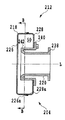
本第二実施形態のコンプレッサハウジング212の、軸心Lを含む面で切断した概略的な断面図を図4に示す。また、本第二実施形態のコンプレッサハウジング212の概略的な分解斜視図を図5に示す。さらに、図6は、コンプレッサハウジング212の、図4のB−B線に沿った概略的な断面図である。なお、上記第一実施形態と同様に、本第二実施形態でも、コンプレッサハウジング212とタービンハウジング214とは概ね同じ構成を有しているので、コンプレッサハウジング212のみにつき以下で説明して、タービンハウジング214の説明は省略する。   FIG. 4 shows a schematic cross-sectional view of the compressor housing 212 of the second embodiment cut along a plane including the axis L. FIG. 5 shows a schematic exploded perspective view of the compressor housing 212 of the second embodiment. FIG. 6 is a schematic cross-sectional view of the compressor housing 212 taken along line BB of FIG. As in the first embodiment, in the second embodiment, the compressor housing 212 and the turbine housing 214 have substantially the same configuration. Therefore, only the compressor housing 212 will be described below. Description of 214 is omitted.

本第二実施形態のコンプレッサハウジング212は、コンプレッサインペラ34の径方向外側に隣接するハウジング本体218と、コンプレッサインペラ34に軸方向に隣接するシュラウド部材220と、を有し、ハウジング本体218とシュラウド部材220とが結合されたものである。   The compressor housing 212 of the second embodiment has a housing body 218 adjacent to the radially outer side of the compressor impeller 34 and a shroud member 220 adjacent to the compressor impeller 34 in the axial direction, and the housing body 218 and the shroud member. 220 is coupled.

ハウジング本体218は、収容されるコンプレッサインペラ34と同じ軸心Lを共通に有し、概ねその軸心Lに関して回転対称形を有している。そして、ハウジング本体218とシュラウド部材220とにより、その挟まれた内部に区画形成される空間である吸気環状通路50は、コンプレッサインペラ34と共通の軸心Lを有し、且つその軸心Lに関して回転対称形を有するようにされている。また、上記第一実施形態と同様に、ハウジング本体218内に区画形成される吸気環状通路50の径方向断面形状は概ね矩形である。そして、吸気環状通路50の径方向内側には、吸気導出通路48が全周に亘って形成されている。   The housing body 218 has the same axis L as that of the compressor impeller 34 to be accommodated, and has a rotationally symmetrical shape with respect to the axis L in general. The intake annular passage 50, which is a space defined by the housing body 218 and the shroud member 220, has a common shaft center L with the compressor impeller 34, and the shaft center L is related to the shaft center L. It has a rotationally symmetric shape. As in the first embodiment, the radial annular cross-section shape of the intake annular passage 50 defined in the housing body 218 is generally rectangular. An intake lead-out passage 48 is formed over the entire circumference on the radially inner side of the intake annular passage 50.

本第二実施形態のハウジング本体218は、上記第一実施形態のハウジング本体54と異なり、リング状部材222と延出部材224との二つの部材が結合された組立体である。   Unlike the housing body 54 of the first embodiment, the housing body 218 of the second embodiment is an assembly in which two members, a ring-shaped member 222 and an extending member 224, are coupled.

本第二実施形態のハウジング本体218のリング状部材222は、軸心Lに直交するB−B線を含む面(図4参照)で半割にされていて、第一ハウジング部材226と、第二ハウジング部材228との二つの部材で構成されている。第一ハウジング部材226も第二ハウジング部材228も、板材をプレス成形することで作製されている。そして、第一ハウジング部材226の接合雌部226aと、第二ハウジング部材228の接合雄部228aとが互いに嵌合されて、溶接により一体とされている(図4参照)。なお、第一ハウジング部材226と第二ハウジング部材228とが一体とされることで、リング状部材222の周壁部230には、図5に示すように、延出部材224の挿嵌用の孔232が形成される。   The ring-shaped member 222 of the housing body 218 according to the second embodiment is halved on a surface (see FIG. 4) including a line BB orthogonal to the axis L, and the first housing member 226, It is comprised by the two members with the two housing members 228. Both the first housing member 226 and the second housing member 228 are produced by press-molding a plate material. And the joining female part 226a of the 1st housing member 226 and the joining male part 228a of the 2nd housing member 228 are mutually fitted, and are united by welding (refer FIG. 4). The first housing member 226 and the second housing member 228 are integrated, so that the peripheral wall 230 of the ring-shaped member 222 has a hole for inserting the extension member 224 as shown in FIG. 232 is formed.

リング状部材222に結合される延出部材224は、リング状部材222から最も離れた一端部に出口側フランジ部233を備え、その他の部分は概ね円筒形とされている。ただし、リング状部材222の孔232に挿嵌される側の延出部材224の挿嵌部234は、斜めの断面を有していて、鋭利な先端部234aを形成している。延出部材224の挿嵌部234は、図6に示すように、リング状部材222の孔232に挿嵌されて、溶接により結合されて一体とされる。このときリング状部材222に挿嵌された挿嵌部234のうち、リング状部材222の外壁部に接していない部分は、リング状部材222内に自由端部分234bを形成することになる。この自由端部分234bは、コンプレッサハウジング212の吸気環状通路50の流路外端部に概ねコンプレッサインペラ34の接線方向に突出するため、当該接線方向に空気を誘導するように作用することになる。なお、延出部材224の基部、すなわちリング状部材222との結合部236は、その断面が矩形とされていても良く、その場合には、自由端部分234bは吸気環状通路50の外周部分全体を遮蔽する仕切部として作用することになる。この場合の仕切部、すなわち自由端部分234bは吸気環状通路50の断面の全体を遮蔽しても良い。   The extending member 224 coupled to the ring-shaped member 222 includes an outlet-side flange portion 233 at one end portion farthest from the ring-shaped member 222, and the other portion is generally cylindrical. However, the insertion part 234 of the extending member 224 on the side inserted into the hole 232 of the ring-shaped member 222 has an oblique cross section and forms a sharp tip 234a. As shown in FIG. 6, the insertion portion 234 of the extending member 224 is inserted into the hole 232 of the ring-shaped member 222 and joined together by welding. At this time, a portion of the insertion portion 234 that is inserted into the ring-shaped member 222 that is not in contact with the outer wall portion of the ring-shaped member 222 forms a free end portion 234 b in the ring-shaped member 222. Since the free end portion 234b protrudes in the tangential direction of the compressor impeller 34 at the outer end of the intake annular passage 50 of the compressor housing 212 in the tangential direction, it acts to guide air in the tangential direction. The base portion of the extending member 224, that is, the coupling portion 236 with the ring-shaped member 222 may have a rectangular cross section. In this case, the free end portion 234b is the entire outer peripheral portion of the intake annular passage 50. It will act as a partitioning part that shields. The partition portion in this case, that is, the free end portion 234b may shield the entire cross section of the intake annular passage 50.

シュラウド部材220は、入口側フランジ部238と、ハウジング本体218との接合部を形成する接合フランジ部240と、ハウジング本体218内に収容される筒状部242とを有している。筒状部242の径方向外側の側面は、ハウジング本体218と共に、吸気環状通路50を区画形成する。また、筒状部242は、コンプレッサインペラ34の羽根34aのシュラウド部と称される曲状端縁34bの回転経路輪郭に倣った形状を径方向内側の側面に有している。このようなシュラウド部材220は、管材を塑性加工することによって一体として成形される。なお、シュラウド部材220は、鋳造により作製されても良い。   The shroud member 220 includes an inlet flange portion 238, a joint flange portion 240 that forms a joint portion with the housing body 218, and a cylindrical portion 242 that is accommodated in the housing body 218. A radially outer side surface of the cylindrical portion 242 defines an intake annular passage 50 together with the housing body 218. Moreover, the cylindrical part 242 has the shape which followed the rotation path | route outline of the curved edge 34b called the shroud part of the blade | wing 34a of the compressor impeller 34 on the radial inner side. Such a shroud member 220 is integrally formed by plastic processing of a pipe material. Note that the shroud member 220 may be manufactured by casting.

なお、本第二実施形態のコンプレッサ12の組立手順は、上記第一実施形態のそれと同様である。   In addition, the assembly procedure of the compressor 12 of the second embodiment is the same as that of the first embodiment.

以上、上記構成である第二実施形態のターボチャージャにより、上記第一実施形態において述べた効果に加えて、以下の効果が奏される。   As described above, in addition to the effects described in the first embodiment, the following effects are achieved by the turbocharger of the second embodiment having the above-described configuration.

吸気環状通路50を構成するハウジング本体218のリング状部材222を、第一ハウジング部材226と第二ハウジング部材228との二つの部材に分け、両者を個別に作製してから互いに結合することにしたので、ターボチャージャ用流体装置であるコンプレッサ12を安価に提供することが可能になる。また、ハウジング本体218は板材や管材を1回あるいは少数回塑性加工し、少数回の接合で作製されるので、ターボチャージャ用流体装置であるコンプレッサ12を安価に提供することが可能になる。これらの効果は、タービンハウジング214を有するタービン16でも同じく奏される。さらに、これを用いることで、安価なターボチャージャ210が提供される。   The ring-shaped member 222 of the housing body 218 constituting the intake annular passage 50 is divided into two members, a first housing member 226 and a second housing member 228, and both are manufactured separately and then coupled to each other. Therefore, the compressor 12 which is a turbocharger fluid device can be provided at low cost. Further, since the housing body 218 is made by plastic processing a plate material or a pipe material once or a small number of times, and is manufactured by a small number of times of joining, it is possible to provide the compressor 12 as a turbocharger fluid device at low cost. These effects are also achieved by the turbine 16 having the turbine housing 214. Further, by using this, an inexpensive turbocharger 210 is provided.

以上、本発明を上記第一および第二実施形態に基づいて説明したが、本発明はそれらに制限されない。   As mentioned above, although this invention was demonstrated based on said 1st and 2nd embodiment, this invention is not restrict | limited to them.

例えば、上記コンプレッサハウジングやタービンハウジングは、共に、ハウジング本体とシュラウド部材とに分割して作製したが、さらに分割されても良い。そして、それら分割作製された複数の部材は、溶接やボルト留め以外にもカシメやリベット留めなどの任意の接合技術を用いて接合され得る。また、各種のハウジング本体内に区画形成される排気環状通路や吸気環状通路の径方向断面形状は矩形である必要はなく、他の任意の形状であっても良い。例えば、ハウジング内の空間の径方向断面形状には、円形、楕円形、三角形等の種々の形状が含まれる。さらには、ハウジング内の空間、特に吸気環状通路や排気環状通路は、環状であれば、コンプレッサインペラやタービンホイールと軸心を共通にせず、互いの軸心がズレていても良い。あるいは、吸気環状通路や排気環状通路といったハウジング内の空間は、それらホイールの軸心に関して厳密に回転対称形であることに限定されず、例えば概ね回転対称形であれば良い。また、吸気環状通路や排気環状通路は、上記第一実施形態の如くハウジング本体のみ、あるいは上記第二実施形態の如くハウジング本体とシュラウド部材とで区画形成される以外に、例えば、上記コンプレッサ側プレート部76の如きセンタハウジング22のフランジ部などの部分をも用いて区画形成されても良い。   For example, both the compressor housing and the turbine housing are divided into a housing body and a shroud member, but may be further divided. And the some member produced by these division | segmentation can be joined using arbitrary joining techniques, such as caulking and riveting, besides welding and bolting. Moreover, the radial cross-sectional shape of the exhaust annular passage and the intake annular passage formed in various housing bodies does not need to be rectangular, and may be any other shape. For example, the radial cross-sectional shape of the space in the housing includes various shapes such as a circle, an ellipse, and a triangle. Furthermore, as long as the space in the housing, particularly the intake annular passage and the exhaust annular passage, are annular, the shaft centers of the compressor impeller and the turbine wheel may not be made common, and the shaft centers may be misaligned. Alternatively, the space in the housing such as the intake annular passage and the exhaust annular passage is not limited to being strictly rotationally symmetric with respect to the axis of the wheel, and may be, for example, substantially rotationally symmetric. Further, the intake annular passage and the exhaust annular passage are formed only by the housing main body as in the first embodiment or by the housing main body and the shroud member as in the second embodiment. A section may also be formed using a portion such as the flange portion of the center housing 22 such as the portion 76.

本発明に係るターボチャージャ用流体装置を用いたターボチャージャの第一実施形態の概略図であり、(a)はターボチャージャの断面図であり、(b)は(a)のターボチャージャのコンプレッサのコンプレッサハウジングの側面図である。BRIEF DESCRIPTION OF THE DRAWINGS It is the schematic of 1st embodiment of the turbocharger using the fluid apparatus for turbochargers concerning this invention, (a) is sectional drawing of a turbocharger, (b) is the compressor of the turbocharger of (a). It is a side view of a compressor housing. 図1のコンプレッサハウジングの、図1(a)のA−A線に沿った断面図である。It is sectional drawing along the AA line of Fig.1 (a) of the compressor housing of FIG. 図1および図2のコンプレッサハウジングの分解斜視図である。FIG. 3 is an exploded perspective view of the compressor housing of FIGS. 1 and 2. 第二実施形態のコンプレッサハウジングの断面図であるIt is sectional drawing of the compressor housing of 2nd embodiment. 図4のコンプレッサハウジングの分解斜視図である。It is a disassembled perspective view of the compressor housing of FIG. 図4および図5のコンプレッサハウジングの、図4のB−B線に沿った断面図である。FIG. 6 is a cross-sectional view of the compressor housing of FIGS. 4 and 5 along the line BB of FIG. 4.

符号の説明Explanation of symbols

10 ターボチャージャ
12 コンプレッサ
14 コンプレッサハウジング
16 タービン
20 ターボロータ
22 センタハウジング
24 タービンハウジング
26 タービン室
28 コンプレッサ室
30 ロータシャフト
32 タービンホイール
34 コンプレッサインペラ
40 排気環状通路
50 吸気環状通路
54 ハウジング本体
56 シュラウド部材
58 リング状部
60 延出部
10 turbocharger 12 compressor 14 compressor housing 16 turbine 20 turbo rotor 22 center housing 24 turbine housing 26 turbine chamber 28 compressor chamber 30 rotor shaft 32 turbine wheel 34 compressor impeller 40 exhaust annular passage 50 intake annular passage 54 housing body 56 shroud member 58 ring -Shaped part 60 extension part

Claims (6)

流体に作用するホイールと、該ホイールの外周を囲み前記流体の流路を構成するハウジングと、を有するターボチャージャ用流体装置であって、
前記ハウジング内の空間は、前記ホイールと軸心を共通にし、且つ前記軸心に関して回転対称形であることを特徴とするターボチャージャ用流体装置。
A turbocharger fluid device comprising: a wheel that acts on a fluid; and a housing that surrounds an outer periphery of the wheel and forms a flow path of the fluid,
The turbocharger fluid device is characterized in that the space in the housing has a common shaft center with the wheel and is rotationally symmetric with respect to the shaft center.
前記ハウジング内の空間の径方向断面形状が矩形であることを特徴とする請求項1に記載のターボチャージャ用流体装置。   2. The turbocharger fluid device according to claim 1, wherein a radial cross-sectional shape of the space in the housing is rectangular. 前記ハウジングは、前記ホイールの径方向外側に隣接するハウジング本体と、前記ホイールに軸方向に隣接するシュラウド部材と、を有し、
前記ハウジング本体と前記シュラウド部材とが結合されたものであることを特徴とする請求項1または2に記載のターボチャージャ用流体装置。
The housing has a housing body adjacent to the outer side in the radial direction of the wheel, and a shroud member adjacent to the wheel in the axial direction,
3. The turbocharger fluid device according to claim 1, wherein the housing body and the shroud member are combined. 4.
前記ハウジング本体および前記シュラウド部材の少なくとも一方は、塑性加工によって製造されることを特徴とする請求項3に記載のターボチャージャ用流体装置。   The turbocharger fluid device according to claim 3, wherein at least one of the housing body and the shroud member is manufactured by plastic working. 前記ハウジング内の空間には、該ハウジングの流路外端部の接線方向に前記流体を向ける仕切部を有することを特徴とする請求項1から4のいずれかに記載のターボチャージャ用流体装置。   The turbocharger fluid device according to any one of claims 1 to 4, wherein the space in the housing has a partition portion for directing the fluid in a tangential direction of an outer end portion of the flow path of the housing. 請求項1から5のいずれかに記載のターボチャージャ用流体装置をタービン側およびコンプレッサ側にそれぞれ有することを特徴とするターボチャージャ。
A turbocharger comprising the turbocharger fluid device according to claim 1 on each of a turbine side and a compressor side.
JP2005340482A 2005-11-25 2005-11-25 Turbocharger and fluid device for turbocharger Pending JP2007146715A (en)

Priority Applications (1)

Application Number Priority Date Filing Date Title
JP2005340482A JP2007146715A (en) 2005-11-25 2005-11-25 Turbocharger and fluid device for turbocharger

Applications Claiming Priority (1)

Application Number Priority Date Filing Date Title
JP2005340482A JP2007146715A (en) 2005-11-25 2005-11-25 Turbocharger and fluid device for turbocharger

Publications (1)

Publication Number Publication Date
JP2007146715A true JP2007146715A (en) 2007-06-14

Family

ID=38208421

Family Applications (1)

Application Number Title Priority Date Filing Date
JP2005340482A Pending JP2007146715A (en) 2005-11-25 2005-11-25 Turbocharger and fluid device for turbocharger

Country Status (1)

Country Link
JP (1) JP2007146715A (en)

Cited By (5)

* Cited by examiner, † Cited by third party
Publication number Priority date Publication date Assignee Title
JP2015212548A (en) * 2014-05-01 2015-11-26 ジェイ. シー. バンフォード エクスカヴェイターズ リミテッドJ.C. Bamford Excavators Limited Air inlet system
JP2017089449A (en) * 2015-11-06 2017-05-25 カルソニックカンセイ株式会社 Turbine housing
JP2017089450A (en) * 2015-11-06 2017-05-25 カルソニックカンセイ株式会社 Turbine housing
US10519806B2 (en) 2015-11-06 2019-12-31 Calsonic Kansei Corporation Turbine housing
JP2020060131A (en) * 2018-10-10 2020-04-16 小島プレス工業株式会社 Supercharger

Cited By (7)

* Cited by examiner, † Cited by third party
Publication number Priority date Publication date Assignee Title
JP2015212548A (en) * 2014-05-01 2015-11-26 ジェイ. シー. バンフォード エクスカヴェイターズ リミテッドJ.C. Bamford Excavators Limited Air inlet system
US10519903B2 (en) 2014-05-01 2019-12-31 Jc Bamford Excavators Limited Air inlet system
JP2017089449A (en) * 2015-11-06 2017-05-25 カルソニックカンセイ株式会社 Turbine housing
JP2017089450A (en) * 2015-11-06 2017-05-25 カルソニックカンセイ株式会社 Turbine housing
US10519806B2 (en) 2015-11-06 2019-12-31 Calsonic Kansei Corporation Turbine housing
JP2020060131A (en) * 2018-10-10 2020-04-16 小島プレス工業株式会社 Supercharger
JP7146554B2 (en) 2018-10-10 2022-10-04 小島プレス工業株式会社 supercharger

Similar Documents

Publication Publication Date Title
JP4047330B2 (en) Independent passage diffuser
CN107076015B (en) The manufacturing method of turbine shroud and turbine shroud
RU2005136641A (en) TWO-STAGE FLOWED TURBOREACTIVE ENGINE, AIR FLOW CONNECTOR AND GROUP OF SUCH DEVICES, AIR FLOW CONNECTION SYSTEM, AND ALSO THE TURBO MACHINE INCLUDING THIS INCLUDED
US10436218B2 (en) Compressor cover, centrifugal compressor, and turbocharger, and compressor cover manufacturing method
RU2591750C2 (en) Supersonic compressor unit (versions) and method for assembly thereof
EP2853694B1 (en) Steam turbine
JP6653326B2 (en) Compressor for exhaust turbocharger
CN209959503U (en) Diagonal fan
JP2007533895A (en) Combined island vane diffuser
JP5866836B2 (en) Centrifugal compressor
JP2007146715A (en) Turbocharger and fluid device for turbocharger
CN105782073A (en) Multistage Radial Compressor Baffle
JP2013506074A (en) Diffuser
EP2966280B1 (en) Turbocharger
JP6589217B2 (en) Rotating machine, method of manufacturing rotating machine
JPH11173296A (en) Diffuser device for pump
JP2016522357A (en) Centrifugal rotor
JP2018135836A (en) Centrifugal compressor
JP7161419B2 (en) Method for manufacturing centrifugal rotating machine, and centrifugal rotating machine
WO2017138560A1 (en) Centrifugal rotary machine
JP2005282548A (en) Barrel shape multistage turbine pump
JP2017510754A (en) Fluid transport device and method of manufacturing fluid transport device
JP2012112351A (en) Gas outlet guide tube of turbine
JP6980028B2 (en) Diffuser and turbocharger
CN107208531A (en) Air-breathing fairing and the compressor for possessing the air-breathing fairing