JP2007146609A - Gate device, and method of replacing main watertight member of gate device - Google Patents
Gate device, and method of replacing main watertight member of gate device Download PDFInfo
- Publication number
- JP2007146609A JP2007146609A JP2005346259A JP2005346259A JP2007146609A JP 2007146609 A JP2007146609 A JP 2007146609A JP 2005346259 A JP2005346259 A JP 2005346259A JP 2005346259 A JP2005346259 A JP 2005346259A JP 2007146609 A JP2007146609 A JP 2007146609A
- Authority
- JP
- Japan
- Prior art keywords
- watertight member
- main
- watertight
- gate device
- door body
- Prior art date
- Legal status (The legal status is an assumption and is not a legal conclusion. Google has not performed a legal analysis and makes no representation as to the accuracy of the status listed.)
- Granted
Links
- 238000000034 method Methods 0.000 title claims description 6
- 238000011144 upstream manufacturing Methods 0.000 claims abstract description 21
- XLYOFNOQVPJJNP-UHFFFAOYSA-N water Substances O XLYOFNOQVPJJNP-UHFFFAOYSA-N 0.000 abstract description 15
- 238000012423 maintenance Methods 0.000 abstract description 5
- 238000010586 diagram Methods 0.000 description 2
- 239000002184 metal Substances 0.000 description 2
- 239000011347 resin Substances 0.000 description 2
- 229920005989 resin Polymers 0.000 description 2
- 239000000463 material Substances 0.000 description 1
Images


Landscapes
- Barrages (AREA)
Abstract
Description
本発明は、たとえば河川に設置され、農業用水などの取水のために用いられる起伏式ゲート装置、及びこのゲート装置の主水密部材を交換する方法に関するものである。 The present invention relates to an undulating gate device that is installed in, for example, a river and is used for water intake such as agricultural water, and a method for replacing a main watertight member of the gate device.
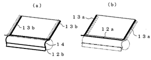
たとえば起伏式ゲート装置には、逆流や漏水を防止するため、特許文献1に開示されているように、扉体の回転軸部や側部に水密部材が設けられている。図5は起伏式ゲート装置の水密部材近傍の拡大図で、(a)は扉体1の回転軸部1aに設置された水密部材2aを、(b)は(a)図のB−B断面図、(c)は(a)図のC−C断面図で、それぞれ回転軸部と側部に設置された水密部材2b,2cを示している。
また、ローラゲートでは、特許文献2に開示されているように、扉体と水密壁の間に水密部材が設けられている。図6はローラゲートの扉体3に設置された水密部材4近傍の拡大図で、(a)は平面から見た図、(b)は水密部材4の拡大図である。
上述したようなゲート装置の水密部材は、使用によって摩耗し、また経年劣化が起こるので、定期的に交換する必要がある。 Since the watertight member of the gate device as described above is worn and deteriorated with use, it is necessary to replace it periodically.
しかしながら、交換に際し、前記水密部材が水没している状態では、水密部材を取り外すと上流側から下流側に水流が発生する。したがって、扉体が水没した状態で水密部材を交換するのは危険であり、別途メンテナンス用の仮設ゲートを設置して水密部材の交換を行っているが、このような交換作業では、期間的にも、コスト的にも問題がある。 However, in the state where the watertight member is submerged at the time of replacement, when the watertight member is removed, a water flow is generated from the upstream side to the downstream side. Therefore, it is dangerous to replace the watertight member with the door submerged, and a separate temporary gate for maintenance is installed to replace the watertight member. However, there is a problem in terms of cost.
本発明が解決しようとする問題点は、従来のゲート装置では、水密部材を交換するに際し、危険を伴うので、別途メンテナンス用の仮設ゲートを設置しなければならなかったという点である。 The problem to be solved by the present invention is that in the conventional gate device, there is a danger when replacing the watertight member, and therefore a temporary gate for maintenance must be separately installed.
本発明のゲート装置は、
別途メンテナンス用の仮設ゲートを設置することなく、安全に水密部材の交換を行えるようにするために、
河川や水路に設置されるゲート装置において、
ゲート装置を構成する扉体の上流側には、上流側から交換が可能なように主水密部材が設置され、
少なくとも前記主水密部材の交換時には、下流側から着脱が可能な副水密部材を、前記主水密部材の下流側に設置可能なように構成したことを最も主要な特徴としている。
The gate device of the present invention is
In order to be able to replace the watertight member safely without installing a temporary gate for maintenance separately,
In gate devices installed in rivers and waterways,
On the upstream side of the door body constituting the gate device, a main watertight member is installed so that it can be replaced from the upstream side,
At least when the main watertight member is replaced, the main feature is that a sub watertight member that can be attached and detached from the downstream side can be installed on the downstream side of the main watertight member.
ゲート装置が起伏式ゲート装置の場合には、前記本発明のゲート装置は、
起伏式ゲート装置を構成する扉体の回転軸部における上流側には主底部水密部材が、また、扉体側部の前記上流側には主側部水密部材が、それぞれ上流側から交換が可能なように設置され、
少なくとも前記主水密部材の交換時には、下流側から着脱が可能な副底部水密部材と副側部水密部材を、前記主底部水密部材と主側部水密部材の下流側に、それぞれ設置可能なように構成したものとなる。
When the gate device is an undulating gate device, the gate device of the present invention is
A main bottom watertight member can be exchanged from the upstream side of the rotating shaft portion of the door body constituting the undulating gate device, and a main side watertight member can be exchanged from the upstream side of the door body side portion. Installed as
At least when replacing the main water-tight member, a sub-bottom water-tight member and a sub-side water-tight member that can be attached and detached from the downstream side can be installed on the downstream side of the main bottom water-tight member and the main side water-tight member, respectively. It will be configured.
前記本発明のゲート装置において、「少なくとも前記主水密部材の交換時には」とは、主水密部材の交換時に副水密部材が設置可能なように構成されていれば良く、主水密部材の交換時以外の場合には、必ずしも副水密部材が設置されていなくても良いことを意味する。 In the gate device of the present invention, “at least when the main watertight member is replaced” may be configured so that the auxiliary watertight member can be installed when the main watertight member is replaced, except when the main watertight member is replaced. In this case, it means that the auxiliary watertight member is not necessarily installed.
前記本発明のゲート装置の主水密部材を交換する場合は、
前記副水密部材を、前記主水密部材の下流側に設置した状態で、前記主水密部材を交換すれば良い。これが、本発明のゲート装置の主水密部材交換方法である。
When replacing the main watertight member of the gate device of the present invention,
What is necessary is just to replace | exchange the said main watertight member in the state which installed the said secondary watertight member in the downstream of the said main watertight member. This is the main watertight member replacement method for the gate device of the present invention.
本発明のゲート装置の主水密部材交換方法において、「設置した状態で」とは、主水密部材の交換時に副水密部材が設置されていれば良く、主水密部材の交換時以外の場合には、必ずしも副水密部材が設置されていなくても良いことを意味する。 In the main water-tight member replacement method of the gate device of the present invention, “in the installed state” means that the sub-water-tight member may be installed when the main water-tight member is replaced. This means that the auxiliary watertight member is not necessarily installed.
本発明では、副水密部材によって水密が保たれるので、主水密部材を取り外しても水流が発生せず、水中での主水密部材の交換作業が、危険を伴わずに行えるようになる。したがって、メンテナンス用の仮設ゲートを設置しなくても良くなり、主水密部材の交換に要する期間やコストを低減できる。 In the present invention, since the watertightness is maintained by the auxiliary watertight member, no water flow is generated even if the main watertight member is removed, and the replacement work of the main watertight member in water can be performed without danger. Therefore, it is not necessary to install a temporary gate for maintenance, and the time and cost required for replacing the main watertight member can be reduced.
以下、本発明を実施するための最良の形態を図1〜図4を用いて詳細に説明する。
図1及び図2は本発明の第1の例を説明する概略図、図3及び図4は本発明の第2の例を説明する概略図である。
Hereinafter, the best mode for carrying out the present invention will be described in detail with reference to FIGS.
1 and 2 are schematic diagrams for explaining a first example of the present invention, and FIGS. 3 and 4 are schematic diagrams for explaining a second example of the present invention.
図1及び図2は本発明の起伏式ゲート装置を示した図で、11は自身を浮上させるだけの浮力を有する扉体である。この扉体11に浮力を備えさせるための構成は特に限定されないが、たとえばパイプと板材で扉体11を形成することで、パイプ部で浮力を得るようにしたものなどが採用される。 FIG. 1 and FIG. 2 are views showing the undulating gate device of the present invention, and 11 is a door body having a buoyancy sufficient to lift itself. The structure for providing the door body 11 with buoyancy is not particularly limited. For example, a structure in which buoyancy is obtained at the pipe portion by forming the door body 11 with a pipe and a plate material or the like is employed.
前記扉体11は、基端側の回転軸部11aを、たとえば港内の底部に設けた基台Bに、滑り軸受やローラ軸受などの軸受によって回転自在に枢支することで、前記回転軸部11aを支点として扉体11の先端側が起伏するようになっている。 The door body 11 is configured such that the rotation shaft portion 11a on the base end side is pivotally supported on a base B provided at the bottom of the port, for example, by a bearing such as a slide bearing or a roller bearing, so that the rotation shaft portion The front end side of the door body 11 is undulated with 11a as a fulcrum.
また、起伏式ゲート装置は、油圧シリンダにて強制的に起伏させる形態であっても良い。 Further, the undulating gate device may be configured to forcibly undulate with a hydraulic cylinder.
ところで、前記のような起伏式ゲート装置では、逆流や漏水を防止するために、扉体11の回転軸部11aや側部11bに水密部材が設けられている。 By the way, in the undulating gate device as described above, a watertight member is provided on the rotating shaft portion 11a and the side portion 11b of the door body 11 in order to prevent backflow and water leakage.
この水密部材を、本発明では、回転軸部11aと側部11bのそれぞれについて、上流側と下流側の2箇所に設置可能な構成としている。
そして、このうちの上流側に設置する主底部水密部材12aと主側部水密部材13aに、従来の底部水密部材、側部水密部材と同様の働きを担わせている。したがって、これらの主底部水密部材12aと主側部水密部材13aは、従来の底部水密部材、側部水密部材と同様の、水密性が高いたとえばゴムが用いられる。
In the present invention, the watertight member is configured to be installed at two locations on the upstream side and the downstream side for each of the rotating shaft portion 11a and the side portion 11b.
Of these, the main bottom watertight member 12a and the main side watertight member 13a installed on the upstream side have the same functions as the conventional bottom watertight member and side watertight member. Accordingly, the main bottom watertight member 12a and the main side watertight member 13a are made of, for example, rubber having the same high watertightness as the conventional bottom watertight member and side watertight member.
但し、本発明では、これらの主底部水密部材12aと主側部水密部材13aは、少なくともこれらの交換時には、下流側にも後述する水密部材を設置する関係で、それぞれ上流側から交換が可能なように設置される。 However, in the present invention, the main bottom watertight member 12a and the main side watertight member 13a can be exchanged from the upstream side at least at the time of exchanging them because a watertight member described later is also installed on the downstream side. It is installed as follows.
12bは副底部水密部材、13bは副側部水密部材である。これらは、前記の主底部水密部材12a、主側部水密部材13aの交換時に、上流側から下流側に向けて水流が発生するのを防止し、前記交換作業を安全に行うために、前記の主底部水密部材12aと主側部水密部材13aの下流側にそれぞれ設置される。 12b is a sub-bottom watertight member, and 13b is a sub-side watertight member. These prevent the occurrence of water flow from the upstream side toward the downstream side when replacing the main bottom watertight member 12a and the main side watertight member 13a, and in order to perform the replacement work safely, It is installed on the downstream side of the main bottom watertight member 12a and the main side watertight member 13a, respectively.
したがって、これらの副底部水密部材12b、副側部水密部材13bは、下流側から着脱できるように構成されている。また、これらの副底部水密部材12b、副側部水密部材13bは、前記交換作業を安全に行えれば、完全な水密状態でなくても良いので、水密性は高くなくても良く、ゴムのほかに樹脂、金属などを使用することができる。
なお、図1中の14は回転軸部11aの水密部材を示す。
Accordingly, the sub-bottom watertight member 12b and the sub-side watertight member 13b are configured to be detachable from the downstream side. Further, these sub-bottom water-tight members 12b and sub-side water-tight members 13b do not have to be completely water-tight as long as the above replacement work can be performed safely, so that the water-tightness may not be high, and the rubber In addition, resin, metal, etc. can be used.
In addition, 14 in FIG. 1 shows the watertight member of the rotating shaft part 11a.
上記構成の本発明の起伏式ゲート装置では、主底部水密部材12a、主側部水密部材13aの交換時は、副底部水密部材12b、副側部水密部材13b、回転軸部11aの水密部材14によって水密が保たれ(図2(a)の太線部分)、水流が発生しないので、上流側から主底部水密部材12a、主側部水密部材13aを取り外して交換すれば良い。
In the undulating gate device of the present invention having the above-described configuration, when replacing the main bottom watertight member 12a and the main side watertight member 13a, the subbottom watertight member 12b, the subside watertight member 13b, and the
なお、回転軸部11aの水密部材14を交換する場合は、主底部水密部材12a、主側部水密部材13aによって水密が保たれ(図2(b)の太線部分)、水流が発生しないので、水密部材14を取り外して交換すれば良い。
In addition, when replacing the
これらの副底部水密部材12b、副側部水密部材13bは、図1に示したように、常時設置していなくても、主底部水密部材12a、主側部水密部材13aの交換時にのみ、設置しても良い。この場合は、主底部水密部材12a、主側部水密部材13aの交換に先立ち、副底部水密部材12bと副側部水密部材13bを下流側から設置することは言うまでもない。 These sub-bottom water-tight members 12b and sub-side water-tight members 13b are installed only when the main bottom water-tight member 12a and the main side water-tight member 13a are replaced as shown in FIG. You may do it. In this case, needless to say, prior to the replacement of the main bottom watertight member 12a and the main side watertight member 13a, the subbottom watertight member 12b and the subside watertight member 13b are installed from the downstream side.
本発明のゲート装置は、図1に示した起伏式のゲート装置に限るものではなく、図3に示したようなローラゲート装置にも適用できる。
この図3に示したようなローラゲート装置の場合、扉体21の上流側と下流側の両縁部21aに、主水密部材22aと副水密部材22bを、扉体21の高さ方向に延長して設置する。
The gate device of the present invention is not limited to the undulating gate device shown in FIG. 1, but can also be applied to a roller gate device as shown in FIG.
In the case of the roller gate device as shown in FIG. 3, the main
この場合も、上流側の主水密部材22aは上流側から、また下流側の副水密部材22bは下流側から交換が可能なように設置する。また、主水密部材22aには、水密性が高いたとえばゴムが用いられること、副水密部材22bは水密性が高くなくても良いので、ゴムのほかに樹脂、金属などを使用することができることも同様である。さらに、この副水密部材22bは、常時設置していなくても、主水密部材22aの交換時にのみ、設置しても良いことも同様である。
Also in this case, the upstream main
本発明は、前記の例に限るものではなく、各請求項に記載の技術的思想の範囲内において、適宜実施の形態を変更しても良いことは言うまでもない。
たとえば、ローラゲート装置の場合は、図3のように扉体21の上流側と下流側の縁部21aでなくても、図4のように上流側或いは下流側の縁部21aの上流側と下流側に主水密部材22aと副水密部材22bを設置しても良い等である。
The present invention is not limited to the above examples, and it is needless to say that the embodiments may be appropriately changed within the scope of the technical idea described in each claim.
For example, in the case of the roller gate device, the upstream side or the downstream side edge 21a as shown in FIG. 4 may be used instead of the upstream side and the downstream side edge 21a as shown in FIG. For example, the main
本発明のゲート装置は、農業用水などの取水のために河川や水路に設置するだけでなく、津波や高潮対策として港湾に設置することも可能である。 The gate device of the present invention can be installed not only in rivers and waterways for water intake such as agricultural water, but also in harbors as a countermeasure against tsunamis and storm surges.
11,21 扉体
11a 回転軸部
11b 側部
12a 主底部水密部材
12b 副底部水密部材
13a 主側部水密部材
13b 副側部水密部材
21a 縁部
22a 主水密部材
22b 副水密部材
11, 21 Door 11a Rotating shaft 11b Side 12a Main bottom watertight member 12b Subbottom watertight member 13a Main side watertight member 13b Subside watertight
Claims (3)
ゲート装置を構成する扉体の上流側には、上流側から交換が可能なように主水密部材が設置され、
少なくとも前記主水密部材の交換時には、下流側から着脱が可能な副水密部材を、前記主水密部材の下流側に設置可能なように構成したことを特徴とするゲート装置。 In gate devices installed in rivers and waterways,
On the upstream side of the door body constituting the gate device, a main watertight member is installed so that it can be replaced from the upstream side,
A gate device characterized in that a sub-watertight member that can be attached and detached from the downstream side can be installed on the downstream side of the main watertight member at least when the main watertight member is replaced.
前記主水密部材が、扉体の回転軸部に設置される主底部水密部材と、扉体側部に設置される主側部水密部材で、
前記副水密部材が、前記主底部水密部材と主側部水密部材の下流側に、それぞれ設置可能な副底部水密部材と副側部水密部材であることを特徴とする請求項1に記載のゲート装置。 In undulating gate devices installed in rivers and waterways,
The main watertight member is a main bottom watertight member installed on the rotating shaft portion of the door body, and a main side watertight member installed on the door body side portion,
2. The gate according to claim 1, wherein the secondary watertight member is a secondary bottom watertight member and a secondary side watertight member that can be installed downstream of the primary bottom watertight member and the primary side watertight member, respectively. apparatus.
前記副水密部材を、前記主水密部材の下流側に設置した状態で、前記主水密部材を交換することを特徴とするゲート装置の主水密部材交換方法。
A method for replacing a main watertight member of a gate device according to claim 1 or 2,
A main watertight member replacement method for a gate device, wherein the main watertight member is replaced in a state where the sub watertight member is installed on the downstream side of the main watertight member.
Priority Applications (1)
| Application Number | Priority Date | Filing Date | Title |
|---|---|---|---|
| JP2005346259A JP4510750B2 (en) | 2005-11-30 | 2005-11-30 | Relief type gate device and main watertight member replacement method for relief type gate device |
Applications Claiming Priority (1)
| Application Number | Priority Date | Filing Date | Title |
|---|---|---|---|
| JP2005346259A JP4510750B2 (en) | 2005-11-30 | 2005-11-30 | Relief type gate device and main watertight member replacement method for relief type gate device |
Publications (2)
| Publication Number | Publication Date |
|---|---|
| JP2007146609A true JP2007146609A (en) | 2007-06-14 |
| JP4510750B2 JP4510750B2 (en) | 2010-07-28 |
Family
ID=38208327
Family Applications (1)
| Application Number | Title | Priority Date | Filing Date |
|---|---|---|---|
| JP2005346259A Active JP4510750B2 (en) | 2005-11-30 | 2005-11-30 | Relief type gate device and main watertight member replacement method for relief type gate device |
Country Status (1)
| Country | Link |
|---|---|
| JP (1) | JP4510750B2 (en) |
Cited By (1)
| Publication number | Priority date | Publication date | Assignee | Title |
|---|---|---|---|---|
| CN105239538A (en) * | 2015-11-23 | 2016-01-13 | 陆伟刚 | Liftable bottom-shaft rotating plane gate and application thereof |
Citations (4)
| Publication number | Priority date | Publication date | Assignee | Title |
|---|---|---|---|---|
| JPS59121028U (en) * | 1983-02-01 | 1984-08-15 | 株式会社クボタ | gate device |
| JPS6358195U (en) * | 1986-10-03 | 1988-04-18 | ||
| JPH01167428U (en) * | 1988-05-11 | 1989-11-24 | ||
| JP2000345539A (en) * | 1999-06-03 | 2000-12-12 | Kyusyu Regional Constr Bureau Ministry Of Constr | Derricking gate |
-
2005
- 2005-11-30 JP JP2005346259A patent/JP4510750B2/en active Active
Patent Citations (4)
| Publication number | Priority date | Publication date | Assignee | Title |
|---|---|---|---|---|
| JPS59121028U (en) * | 1983-02-01 | 1984-08-15 | 株式会社クボタ | gate device |
| JPS6358195U (en) * | 1986-10-03 | 1988-04-18 | ||
| JPH01167428U (en) * | 1988-05-11 | 1989-11-24 | ||
| JP2000345539A (en) * | 1999-06-03 | 2000-12-12 | Kyusyu Regional Constr Bureau Ministry Of Constr | Derricking gate |
Cited By (1)
| Publication number | Priority date | Publication date | Assignee | Title |
|---|---|---|---|---|
| CN105239538A (en) * | 2015-11-23 | 2016-01-13 | 陆伟刚 | Liftable bottom-shaft rotating plane gate and application thereof |
Also Published As
| Publication number | Publication date |
|---|---|
| JP4510750B2 (en) | 2010-07-28 |
Similar Documents
| Publication | Publication Date | Title |
|---|---|---|
| JP4705086B2 (en) | Hydroelectric generator | |
| JP2009228608A (en) | Hydraulic power generation device | |
| JP4510750B2 (en) | Relief type gate device and main watertight member replacement method for relief type gate device | |
| JP6348035B2 (en) | Drainage mass and drainage system equipped with it | |
| JP4770681B2 (en) | Vertical shaft pump | |
| JP3455136B2 (en) | Undulating gate | |
| JP2019035189A (en) | Transfer bridge | |
| JP5132558B2 (en) | Water utilization facilities and methods using waterways | |
| JP7382652B2 (en) | flap gate | |
| JP3957213B2 (en) | Sand removal structure of floating undulating gate facility | |
| JP6138522B2 (en) | Undulating gate breakwater | |
| KR200323139Y1 (en) | Side Rubber Seal of Traveling Water Screen | |
| KR20140040590A (en) | Water proof bolt cover | |
| CN213979240U (en) | Waterproof composite well lid | |
| JP2005171691A (en) | Pier-less gate | |
| KR200316598Y1 (en) | Assembly manhole structure for waterworks to mount valve | |
| CN201053118Y (en) | Ship lock under bridge | |
| JP2011184933A (en) | Rainwater drainage system, and construction method of the same | |
| JP2008025358A (en) | Ocean current energy increasing device | |
| KR101922994B1 (en) | Sluice to prevent water leakage in two way | |
| JP2008063820A (en) | Structure of flap gate | |
| Malito et al. | Intended vs unintended consequences of re-routing a coastal river channel | |
| KR20140016686A (en) | Movable pollution prevention device | |
| KR200217687Y1 (en) | Sluice gate for water supply and wastewater | |
| JPH11100831A (en) | Support structure for fence end section |
Legal Events
| Date | Code | Title | Description |
|---|---|---|---|
| A621 | Written request for application examination |
Free format text: JAPANESE INTERMEDIATE CODE: A621 Effective date: 20080912 |
|
| A977 | Report on retrieval |
Free format text: JAPANESE INTERMEDIATE CODE: A971007 Effective date: 20091214 |
|
| A131 | Notification of reasons for refusal |
Free format text: JAPANESE INTERMEDIATE CODE: A131 Effective date: 20100112 |
|
| A521 | Request for written amendment filed |
Free format text: JAPANESE INTERMEDIATE CODE: A523 Effective date: 20100305 |
|
| TRDD | Decision of grant or rejection written | ||
| A01 | Written decision to grant a patent or to grant a registration (utility model) |
Free format text: JAPANESE INTERMEDIATE CODE: A01 Effective date: 20100406 |
|
| A01 | Written decision to grant a patent or to grant a registration (utility model) |
Free format text: JAPANESE INTERMEDIATE CODE: A01 |
|
| A61 | First payment of annual fees (during grant procedure) |
Free format text: JAPANESE INTERMEDIATE CODE: A61 Effective date: 20100430 |
|
| FPAY | Renewal fee payment (event date is renewal date of database) |
Free format text: PAYMENT UNTIL: 20130514 Year of fee payment: 3 |
|
| R150 | Certificate of patent or registration of utility model |
Ref document number: 4510750 Country of ref document: JP Free format text: JAPANESE INTERMEDIATE CODE: R150 Free format text: JAPANESE INTERMEDIATE CODE: R150 |
|
| FPAY | Renewal fee payment (event date is renewal date of database) |
Free format text: PAYMENT UNTIL: 20140514 Year of fee payment: 4 |
|
| R250 | Receipt of annual fees |
Free format text: JAPANESE INTERMEDIATE CODE: R250 |