JP2007143261A - Inverter and method of driving same, and light emitting apparatus and liquid crystal television using same - Google Patents
Inverter and method of driving same, and light emitting apparatus and liquid crystal television using same Download PDFInfo
- Publication number
- JP2007143261A JP2007143261A JP2005332199A JP2005332199A JP2007143261A JP 2007143261 A JP2007143261 A JP 2007143261A JP 2005332199 A JP2005332199 A JP 2005332199A JP 2005332199 A JP2005332199 A JP 2005332199A JP 2007143261 A JP2007143261 A JP 2007143261A
- Authority
- JP
- Japan
- Prior art keywords
- side transistor
- wave signal
- triangular wave
- voltage
- turned
- Prior art date
- Legal status (The legal status is an assumption and is not a legal conclusion. Google has not performed a legal analysis and makes no representation as to the accuracy of the status listed.)
- Granted
Links
Images


Classifications
-
- Y02B20/202—
Abstract
Description
本発明は、蛍光ランプなどに駆動電圧を供給するインバータに関し、特にインバータの駆動方式に関する。 The present invention relates to an inverter that supplies a drive voltage to a fluorescent lamp or the like, and more particularly, to an inverter drive system.
近年、ブラウン管テレビに代えて、薄型、大型化が可能な液晶テレビの普及が進んでいる。液晶テレビは、映像が表示される液晶パネルの背面に、冷陰極蛍光ランプ(Cold Cathode Fluorescent Lamp、以下CCFLという)や、外部電極蛍光ランプ(External Electrode Fluorescent Lamp、以下、EEFLという)を複数本配置し、バックライトとして発光させている。 In recent years, instead of cathode-ray tube televisions, liquid crystal televisions that can be made thin and large have become popular. A liquid crystal television has a plurality of cold cathode fluorescent lamps (hereinafter referred to as CCFL) and external electrode fluorescent lamps (hereinafter referred to as EEFL) arranged on the back of a liquid crystal panel on which images are displayed. The light is emitted as a backlight.
CCFLやEEFLの駆動には、たとえば12V程度の直流電圧を昇圧して交流電圧として出力するインバータ(DC/ACコンバータ)が用いられる。インバータは、CCFLに流れる電流を電圧に変換して制御回路に帰還し、この帰還された電圧にもとづいてスイッチング素子のオンオフを制御している。たとえば、特許文献1には、こうしたインバータによるCCFLの駆動技術が開示される。
For driving CCFL and EEFL, an inverter (DC / AC converter) that boosts a DC voltage of about 12 V and outputs it as an AC voltage, for example, is used. The inverter converts the current flowing through the CCFL into a voltage and feeds it back to the control circuit, and controls on / off of the switching element based on the fed back voltage. For example,
インバータによって昇圧された交流電圧を生成するためには、トランスの1次側コイルに間欠的にスイッチング電圧を与え、エネルギを蓄える必要がある。トランスの1次側コイルにスイッチング電圧を与えるために、4つのスイッチングトランジスタを、Hブリッジ回路あるいはフルブリッジ回路と呼ばれる構成に配置し、1次側コイルの両端にスイッチング電圧を与える手法がとられる場合がある。 In order to generate the alternating voltage boosted by the inverter, it is necessary to intermittently apply a switching voltage to the primary coil of the transformer to store energy. In order to apply a switching voltage to the primary coil of the transformer, a method is adopted in which four switching transistors are arranged in a configuration called an H-bridge circuit or a full-bridge circuit and the switching voltage is applied to both ends of the primary coil. There is.
こうしたHブリッジ回路を用いてスイッチング電圧を生成する場合、各スイッチングトランジスタのオンオフのタイミングは、インバータの効率に大きな影響を及ぼす。また、Hブリッジ回路を構成するスイッチングトランジスタのうち、入力電圧と接地間に直列に接続された1対のトランジスタが、同時にオンすると貫通電流が流れてしまうため、デッドタイムを設けてスイッチング制御を行う必要がある。 When a switching voltage is generated using such an H-bridge circuit, the on / off timing of each switching transistor greatly affects the efficiency of the inverter. Further, among the switching transistors constituting the H-bridge circuit, when a pair of transistors connected in series between the input voltage and the ground are simultaneously turned on, a through current flows, so that switching control is performed with dead time. There is a need.
本発明はこうした課題に鑑みてなされたものであり、その目的は、Hブリッジ回路を用いたインバータのスイッチングトランジスタのオンオフのタイミングを、柔軟に設定可能なインバータの提供にある。 The present invention has been made in view of these problems, and an object thereof is to provide an inverter that can flexibly set the ON / OFF timing of the switching transistor of the inverter using the H-bridge circuit.
本発明のある態様のインバータは、トランスと、一端が入力電圧の印加される入力端子に接続され、他端がトランスの1次側コイルの第1端子に接続された第1ハイサイドトランジスタと、一端が電位の固定された電位固定端子に接続され、他端が1次側コイルの第1端子に接続された第1ローサイドトランジスタと、一端が入力端子に接続され、他端が1次側コイルの第2端子に接続された第2ハイサイドトランジスタと、一端が電位固定端子に接続され、他端が1次側コイルの第2端子に接続された第2ローサイドトランジスタと、トランスの2次側コイルの電流を電圧に変換し、検出電圧として出力する電流電圧変換部と、三角波信号を生成する三角波信号生成部と、検出電圧と所定の基準電圧との誤差に応じた誤差電圧を出力する誤差増幅器と、誤差増幅器から出力される誤差電圧および三角波信号生成部により生成される三角波信号にもとづき、第1、第2ハイサイドトランジスタおよび第1、第2ローサイドトランジスタのオンオフを制御する論理制御部と、を備える。論理制御部は、三角波信号がボトムエッジから誤差電圧に達するまでの第1期間に、第1ハイサイドトランジスタおよび第2ローサイドトランジスタをオンし、次に三角波信号がピークエッジに達するまでの第2期間に、第1ハイサイドトランジスタをオンし、次に三角波信号がボトムエッジに達するまでの第3期間に、第2ハイサイドトランジスタをオンし、次に三角波信号が再度誤差電圧に達するまでの第4期間に、第1ローサイドトランジスタおよび第2ハイサイドトランジスタをオンし、次に三角波信号が再度ピークエッジに達するまでの第5期間に、第2ハイサイドトランジスタをオンし、次に三角波信号が再度ボトムエッジに達するまでの第6期間に、第1ハイサイドトランジスタをオンする。 An inverter according to an aspect of the present invention includes a transformer, a first high-side transistor having one end connected to an input terminal to which an input voltage is applied, and the other end connected to a first terminal of a primary coil of the transformer, A first low-side transistor having one end connected to a fixed potential terminal having a fixed potential and the other end connected to the first terminal of the primary side coil; one end connected to the input terminal; the other end connected to the primary side coil A second high-side transistor connected to the second terminal, a second low-side transistor having one end connected to the potential fixing terminal and the other end connected to the second terminal of the primary coil, and the secondary side of the transformer A current-voltage converter that converts the coil current into a voltage and outputs it as a detection voltage, a triangular wave signal generator that generates a triangular wave signal, and an error that outputs an error voltage corresponding to the error between the detected voltage and a predetermined reference voltage An amplifier, and a logic control unit for controlling on / off of the first and second high-side transistors and the first and second low-side transistors based on the error voltage output from the error amplifier and the triangular wave signal generated by the triangular wave signal generating unit; . The logic control unit turns on the first high-side transistor and the second low-side transistor in the first period until the triangular wave signal reaches the error voltage from the bottom edge, and then the second period until the triangular wave signal reaches the peak edge. In the third period until the first high-side transistor is turned on and then the triangular wave signal reaches the bottom edge, the second high-side transistor is turned on, and the fourth time until the triangular wave signal reaches the error voltage again. In the period, the first low-side transistor and the second high-side transistor are turned on, and then the second high-side transistor is turned on in the fifth period until the triangular wave signal reaches the peak edge again. In the sixth period until reaching the edge, the first high-side transistor is turned on.
この態様では、Hブリッジ回路を構成する第1、第2ハイサイドトランジスタおよび第1、第2ローサイドトランジスタを、トランスの2次側コイルに流れる電流をモニタし、三角波信号と比較することにより駆動する。その結果、三角波信号の形状を調節することにより、各トランジスタのオンオフのタイミングを調節することができる。 In this aspect, the first and second high-side transistors and the first and second low-side transistors constituting the H-bridge circuit are driven by monitoring the current flowing in the secondary coil of the transformer and comparing it with the triangular wave signal. . As a result, the on / off timing of each transistor can be adjusted by adjusting the shape of the triangular wave signal.
論理制御部は、第5期間において、三角波信号が誤差電圧に達してから、所定の第1オフ時間が経過するまでの期間、第1ハイサイドトランジスタをオフし、第1オフ時間経過後に、第1ハイサイドトランジスタをオンしてもよい。 The logic control unit turns off the first high-side transistor during a period from when the triangular wave signal reaches the error voltage until a predetermined first off time elapses in the fifth period, and after the first off time elapses, One high side transistor may be turned on.
第5期間に第1ハイサイドトランジスタをオフし続けると、電流が第1ハイサイドトランジスタのボディダイオード(寄生ダイオード)に流れるため、順方向電圧Vf分の電圧降下が発生し、電力損失が大きくなる。そこで、第5期間において、所定の第1オフ時間が経過した後に、第1ハイサイドトランジスタをオンすることにより、ボディダイオードに流れていた電流を、第1ハイサイドトランジスタに流すことにより電力損失を低減することができる。また、第1オフ時間を適切に設定することにより、第1ハイサイドトランジスタと第1ローサイドトランジスタが同時にオンして貫通電流が流れるのを防止することができる。 If the first high-side transistor is kept off during the fifth period, the current flows through the body diode (parasitic diode) of the first high-side transistor, so that a voltage drop corresponding to the forward voltage Vf occurs, resulting in a large power loss. . Therefore, in the fifth period, after a predetermined first off-time has elapsed, the first high-side transistor is turned on, so that the current flowing through the body diode flows through the first high-side transistor, thereby reducing the power loss. Can be reduced. In addition, by appropriately setting the first off time, it is possible to prevent the through current from flowing due to the first high-side transistor and the first low-side transistor being simultaneously turned on.
論理制御部は、第2期間において、三角波信号が誤差電圧に達してから、所定の第2オフ時間が経過するまでの期間、第2ハイサイドトランジスタをオフし、第2オフ時間経過後に、第2ハイサイドトランジスタをオンしてもよい。 The logic control unit turns off the second high-side transistor during a period from when the triangular wave signal reaches the error voltage until a predetermined second off time elapses in the second period, and after the second off time elapses, 2 The high-side transistor may be turned on.
第2期間においても、第2ハイサイドトランジスタをオフし続けると、ボディダイオードに電流が流れて電力損失が大きくなる。そこで、所定の第2オフ時間が経過した後に、第2ハイサイドトランジスタをオンに切り換えることにより、電力損失を低減することができる。また、第2オフ時間を適切に設定することにより、第2ハイサイドトランジスタと第2ローサイドトランジスタが同時にオンして貫通電流が流れるのを防止することができる。 Even in the second period, if the second high-side transistor is kept off, a current flows through the body diode and power loss increases. Therefore, power loss can be reduced by switching on the second high-side transistor after a predetermined second off time has elapsed. In addition, by appropriately setting the second off time, it is possible to prevent the through current from flowing due to the second high side transistor and the second low side transistor being simultaneously turned on.
三角波信号のボトムエッジからピークエッジまでの遷移時間を、ピークエッジからボトムエッジまでの遷移時間の2倍から100倍の範囲に、より好ましくは5倍から15倍の範囲に設定してもよい。この場合、1次側コイルの通電時間および非通電時間に対する、デッドタイムの割合を好適に設定することができる。 The transition time from the bottom edge to the peak edge of the triangular wave signal may be set in the range of 2 to 100 times, more preferably in the range of 5 to 15 times the transition time from the peak edge to the bottom edge. In this case, the ratio of the dead time to the energization time and the non-energization time of the primary coil can be suitably set.
論理制御部は、ピークエッジとボトムエッジを反転して、第1、第2ハイサイドトランジスタおよび第1、第2ローサイドトランジスタのオンオフを制御してもよい。また、第1、第2ハイサイドトランジスタ、第1、第2ローサイドトランジスタをMOSFETで構成してもよい。 The logic control unit may invert the peak edge and the bottom edge to control on / off of the first and second high-side transistors and the first and second low-side transistors. Further, the first and second high-side transistors and the first and second low-side transistors may be constituted by MOSFETs.
三角波信号生成部と、誤差増幅器と、論理制御部と、を1つの半導体基板上に一体集積化してもよい。「一体集積化」とは、回路の構成要素のすべてが半導体基板上に形成される場合や、回路の主要構成要素が一体集積化される場合が含まれ、回路定数の調節用に一部の抵抗やキャパシタなどが半導体基板の外部に設けられていてもよい。これらの回路素子を1つのLSIとして集積化することにより、回路面積を削減することができる。 The triangular wave signal generation unit, the error amplifier, and the logic control unit may be integrated on a single semiconductor substrate. “Integrated integration” includes the case where all of the circuit components are formed on a semiconductor substrate and the case where the main components of the circuit are integrated. A resistor, a capacitor, or the like may be provided outside the semiconductor substrate. By integrating these circuit elements as one LSI, the circuit area can be reduced.
本発明の別の態様は、発光装置である。この発光装置は、蛍光ランプと、蛍光ランプに駆動電圧を供給する上述のインバータと、を備える。インバータは2つであって、蛍光ランプの両端にそれぞれ設けられ、互いに逆相となる駆動電圧を供給してもよい。また、蛍光ランプは、冷陰極管蛍光ランプであってもよく、外部電極蛍光ランプであってもよい。 Another embodiment of the present invention is a light-emitting device. The light emitting device includes a fluorescent lamp and the above-described inverter that supplies a driving voltage to the fluorescent lamp. Two inverters may be provided at both ends of the fluorescent lamp, and drive voltages having opposite phases may be supplied. The fluorescent lamp may be a cold cathode fluorescent lamp or an external electrode fluorescent lamp.
この態様によると、インバータの効率とともに、蛍光ランプの発光効率を調節することができるため、装置全体の効率を改善することができる。 According to this aspect, since the luminous efficiency of the fluorescent lamp can be adjusted together with the efficiency of the inverter, the efficiency of the entire apparatus can be improved.
本発明のさらに別の態様は、液晶テレビである。この液晶テレビは、液晶パネルと、液晶パネルの背面に配置される複数の上述の発光装置と、を備える。 Yet another embodiment of the present invention is a liquid crystal television. This liquid crystal television includes a liquid crystal panel and a plurality of the above-described light emitting devices disposed on the back surface of the liquid crystal panel.
なお、以上の構成要素の任意の組合せや、本発明の構成要素や表現を、方法、装置、システムなどの間で相互に置換したものもまた、本発明の態様として有効である。 It should be noted that any combination of the above-described constituent elements, or those obtained by replacing constituent elements and expressions of the present invention with each other among methods, apparatuses, systems, etc. are also effective as an aspect of the present invention.
本発明に係るインバータによれば、Hブリッジ回路を用いたインバータのスイッチングトランジスタのオンオフのタイミングを、柔軟に設定することができる。 According to the inverter of the present invention, the on / off timing of the switching transistor of the inverter using the H bridge circuit can be set flexibly.
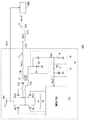
図1は、本発明の実施の形態に係る発光装置200の構成を示す回路図である。図2は、図1の発光装置200が搭載される液晶テレビ300の構成を示すブロック図である。液晶テレビ300は、アンテナ310と接続される。アンテナ310は、放送波を受信して受信部304に受信信号を出力する。受信部304は、受信信号を検波、増幅して、信号処理部306へと出力する。信号処理部306は、変調されたデータを復調して得られる画像データを液晶ドライバ308に出力する。液晶ドライバ308は、画像データを走査線ごとに液晶パネル302へと出力し、映像、画像を表示する。液晶パネル302の背面には、バックライトとして複数の発光装置200が配置されている。本実施の形態に係る発光装置200は、このような液晶パネル302のバックライトとして好適に用いることができる。以下、図1に戻り、発光装置200の構成および動作について詳細に説明する。
FIG. 1 is a circuit diagram showing a configuration of a
本実施の形態に係る発光装置200は、EEFL210、第1インバータ100a、第2インバータ100bを含む。EEFL210は、液晶パネル302の背面に配置される。第1インバータ100a、第2インバータ100bは、DC/ACコンバータであり、直流電源から出力される入力電圧Vinを交流電圧に変換して昇圧し、EEFL210の第1端子212、第2端子214に、それぞれ、第1駆動電圧Vdrv1、第2駆動電圧Vdrv2を供給する。第1駆動電圧Vdrv1、第2駆動電圧Vdrv2は、互いに逆相となる交流電圧である。
The
図1において、EEFL210は1つ示されているが、複数を並列に配置してもよい。以下、本実施の形態に係る第1インバータ100a、第2インバータ100bの構成について説明する。第1インバータ100a、第2インバータ100bは同様の構成となっているため、以下では、両者を区別せずに、インバータ100と総称して説明を行う。
Although one
インバータ100は、Hブリッジ回路10、トランス12、電流電圧変換部14、制御回路20、キャパシタC10を含む。
The inverter 100 includes an
Hブリッジ回路10は、第1ハイサイドトランジスタMH1、第1ローサイドトランジスタML1、第2ハイサイドトランジスタMH2、第2ローサイドトランジスタML2の4つのパワートランジスタを含む。
The
第1ハイサイドトランジスタMH1は、一端が、入力電圧の印加される入力端子102に接続され、他端が、トランス12の1次側コイル12aの第1端子に接続される。第1ローサイドトランジスタML1は、一端が、電位の固定された接地端子に接続され、他端が1次側コイル12aの第1端子に接続される。第2ハイサイドトランジスタMH2は、一端が、入力端子102に接続され、他端が、直流阻止用のキャパシタC10を介して1次側コイルの第2端子に接続される。第2ローサイドトランジスタML2は、一端が、接地端子に接続され、他端が、直流阻止用のキャパシタC10を介して1次側コイル12aの第2端子に接続される。
One end of the first high-side transistor MH1 is connected to the
電流電圧変換部14は、トランス12の2次側コイル12bと接地間に設けられる。電流電圧変換部14は、2次側コイル12bに流れる電流、すなわちEEFL210に流れる電流を電圧に変換し、検出電圧Vdet’として出力する。電流電圧変換部14は、整流回路16、フィルタ18を含む。
The current-
整流回路16は、第1ダイオードD1、第2ダイオードD2、抵抗R1を含む。第1ダイオードD1はアノードが接地され、カソードが2次側コイル12bの一端に接続されている。第2ダイオードD2のアノードは、第1ダイオードD1のカソードと接続される。抵抗R1は、第2ダイオードD2のカソードと接地間に設けられる。2次側コイル12bに流れる交流の電流は、第1ダイオードD1、第2ダイオードD2によって半波整流され、抵抗R1に流れる。抵抗R1には、2次側コイル12bに流れる電流に比例した電圧降下が発生する。整流回路16は、抵抗R1で発生した電圧降下を、検出電圧Vdetとして出力する。
The
フィルタ18は、抵抗R2、キャパシタC1を含むローパスフィルタである。フィルタ18は、検出電圧Vdetの高周波成分を除去した検出電圧Vdet’を、制御回路20に帰還する。
The
制御回路20は、帰還された検出電圧Vdet’にもとづき、Hブリッジ回路10の第1ハイサイドトランジスタMH1、第1ローサイドトランジスタML1、第2ハイサイドトランジスタMH2、第2ローサイドトランジスタML2のオンオフを制御する。Hブリッジ回路10の制御によって、トランス12の1次側コイル12aに、スイッチング電圧が供給される。その結果、トランス12でエネルギ変換が行われ、2次側コイル12bに接続されたEEFL210には、第1駆動電圧Vdrv1が供給される。
The
以下、制御回路20の構成について説明する。図3は、本実施の形態に係る制御回路20の構成を示す回路図である。制御回路20は、誤差増幅器22、PWMコンパレータ24、三角波信号生成部30、論理制御部40を含み、1つの半導体基板上に一体集積化された機能ICである。
Hereinafter, the configuration of the
誤差増幅器22の非反転入力端子には、電流電圧変換部14から帰還された検出電圧Vdet’が入力され、反転入力端子には、所定の基準電圧Vrefが入力される。基準電圧Vrefは、EEFL210の発光輝度に応じて決定される。誤差増幅器22は、検出電圧Vdet’と、基準電圧Vrefとの誤差に応じた誤差電圧Verrを出力する。
The detection voltage Vdet ′ fed back from the current /
三角波信号生成部30は所定の周波数の三角波状の三角波信号Voscを生成する。図4は、三角波信号生成部30の構成例を示す回路図である。三角波信号生成部30は、第1コンパレータ32、第2コンパレータ34、RSフリップフロップ36、第1定電流源38a、第2定電流源38b、キャパシタC2を含む。
The triangular
この三角波信号生成部30は、一般的な構成であるので、構成および動作については簡単に説明するにとどめる。第1定電流源38aは、一端が接地されたキャパシタC2を充電するための電流源であり、第2定電流源38bは、キャパシタC2を放電するための電流源である。キャパシタC2に現れる電圧が、三角波信号Voscとして出力される。
Since the triangular wave
第1コンパレータ32は、三角波信号Voscの電位を、出力すべき三角波信号のピーク値を設定する最大電圧Vmaxと比較する。第1コンパレータ32は、Vosc>Vmaxとなるとハイレベルを出力する。また、第2コンパレータ34は、三角波信号Voscの電位を、出力すべき三角波信号のボトム値を設定する最小電圧Vminと比較する。第2コンパレータ34は、Vosc<Vminとなるとハイレベルを出力する。
The
第1コンパレータ32、第2コンパレータ34の出力信号は、それぞれRSフリップフロップ36のセット端子、リセット端子に入力される。RSフリップフロップ36の出力信号Vqは、第1定電流源38aに出力され、反転出力信号*Vqは、第2定電流源38bへと出力される。第1定電流源38aは、出力信号Vqがハイレベルのときオンし、定電流Ic1によりキャパシタC2を充電する。また、第2定電流源38bは、反転出力信号*Vqがハイレベルのときにオンし、定電流Ic2によりキャパシタC2を放電する。
The output signals of the
以上のように構成された三角波信号生成部30からは、ピーク電圧がVmax、ボトム電圧がVminに設定された三角波信号Voscが出力される。また、RSフリップフロップ36の出力信号Vqが、周期信号として論理制御部40へと出力される。なお、三角波信号生成部30は、ヒステリシスコンパレータを用いて構成してもよい。
The triangular
図3に戻る。PWMコンパレータ24は、誤差増幅器22から出力される誤差電圧Verrと、三角波信号生成部30から出力される三角波信号Voscと、を比較し、Verr<Voscのときハイレベル、Verr>Voscのときローレベルとなるパルス幅変調信号(以下、PWM信号という)Vpwmを生成する。このPWM信号Vpwmは、三角波信号Vosc、周期信号Vqとともに、論理制御部40に入力される。
Returning to FIG. The
論理制御部40は、PWM信号Vpwm、三角波信号Vosc、周期信号Vqにもとづき、Hブリッジ回路10の第1ハイサイドトランジスタMH1、第1ローサイドトランジスタML1、第2ハイサイドトランジスタMH2、第2ローサイドトランジスタML2のオンオフを制御する。以下、論理制御部40について説明する。
The
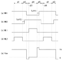
論理制御部40は、三角波信号生成部30から出力される三角波信号Voscの2周期を1サイクルとしてHブリッジ回路10を制御する。より具体的には、三角波信号Voscの2周期を、第1から第6の6つの期間に分割し、スイッチング制御を行う。図5(a)〜(h)は、インバータ100の動作状態を示すタイムチャートである。図5(a)は、誤差電圧Verrおよび三角波信号Voscを、同図(b)は、PWM信号Vpwmを、同図(c)は、周期信号Vqを、同図(d)〜(g)はそれぞれ、第1ハイサイドトランジスタMH1、第2ハイサイドトランジスタMH2、第1ローサイドトランジスタML1、第2ローサイドトランジスタML2の状態を、同図(h)は、トランス12の1次側コイル12aの第1端子の電位Vswを示す。同図(d)〜(g)において、ハイレベルがトランジスタがオンの状態を、ローレベルがトランジスタがオフの状態を示す。また、同図において、縦軸および横軸は説明を簡潔にするために適宜拡大、縮小されている。
The
はじめに、第1期間φ1から第6期間φ6の分割について説明する。論理制御部40は、三角波信号Voscがそのボトムエッジから誤差電圧Verrに達するまでの期間を第1期間φ1とする。次に三角波信号Voscがピークエッジに達するまでの期間を第2期間φ2とする。次に三角波信号Voscがボトムエッジに達するまでの期間を第3期間φ3とする。次に三角波信号Voscが再度誤差電圧Verrに達するまでの期間を第4期間φ4とする。次に三角波信号Voscが再度ピークエッジに達するまでの期間を第5期間φ5とする。次に三角波信号Voscが再度ボトムエッジに達するまでの期間を第6期間φ6とする。この分割は、PWM信号Vpwmおよび周期信号Vqにもとづいて、一般的な論理回路を用いて構成することができる。
First, the division from the first period φ1 to the sixth period φ6 will be described. The
次に、第1期間φ1から第6期間φ6におけるHブリッジ回路10のトランジスタのオンオフ状態について説明する。
論理制御部40は、第1期間φ1において、第1ハイサイドトランジスタMH1および第2ローサイドトランジスタML2をオンし、その他のトランジスタをオフする。続く第2期間φ2において、第1ハイサイドトランジスタMH1をオンし、その他のトランジスタをオフする。続く第3期間φ3において、第2ハイサイドトランジスタMH2をオンし、その他のトランジスタをオフする。続く第4期間φ4において、第1ローサイドトランジスタML1および第2ハイサイドトランジスタMH2をオンし、その他のトランジスタをオフする。続く第5期間φ5において、第2ハイサイドトランジスタMH2をオンし、その他のトランジスタをオフする。続く第6期間φ6において、第1ハイサイドトランジスタMH1をオンし、その他のトランジスタをオフする。その後、第1期間φ1へと戻る。
Next, the on / off state of the transistors of the
In the first period φ1, the
以上のように構成された本実施の形態に係るインバータ100の動作を説明する。図6(a)から(f)は、本実施の形態に係るインバータ100のHブリッジ回路10の電流の流れを示す回路図である。図6(a)から(f)は、それぞれ、第1期間φ1〜第6期間φ6の各トランジスタのオンオフ状態およびコイル電流Iswの状態を示している。
The operation of inverter 100 according to the present embodiment configured as described above will be described. FIGS. 6A to 6F are circuit diagrams showing a current flow in the H-
図6(a)に示すように、第1期間φ1では、第1ハイサイドトランジスタMH1、第2ローサイドトランジスタML2がオンとなる。その結果、コイル電流Iswは、第1ハイサイドトランジスタMH1、1次側コイル12a、第2ローサイドトランジスタML2の経路に流れる。このときのスイッチング電圧Vswは、入力電圧Vinにほぼ等しい電圧となる。第1期間φ1に、コイル電流Iswは徐々に大きくなっていく。
As shown in FIG. 6A, in the first period φ1, the first high-side transistor MH1 and the second low-side transistor ML2 are turned on. As a result, the coil current Isw flows through the path of the first high side transistor MH1, the
続く第2期間φ2では、図6(b)に示すように、第2ローサイドトランジスタML2がオフされ、第1ハイサイドトランジスタMH1のみがオンとなる。その結果、1次側コイル12aに蓄えられたエネルギによって、第2ハイサイドトランジスタMH2のボディダイオードに回生電流が流れる。この間、スイッチング電圧Vswは、入力電圧にほぼ等しい電圧を維持する。
In the subsequent second period φ2, as shown in FIG. 6B, the second low-side transistor ML2 is turned off and only the first high-side transistor MH1 is turned on. As a result, the regenerative current flows through the body diode of the second high-side transistor MH2 due to the energy stored in the
次に、第3期間φ3では、図6(c)に示すように、第2ハイサイドトランジスタMH2がオンに切り換えられ、第1ハイサイドトランジスタMH1がオフされる。このとき、第2期間φ2において第1ハイサイドトランジスタMH1から供給されていたコイル電流Iswは、第1ローサイドトランジスタML1のボディダイオードを介して接地から供給されることになる。第3期間φ3のスイッチング電圧Vswは、接地電位(0V)よりも第1ローサイドトランジスタML1のボディダイオードの順方向電圧Vfだけ低い負の値となる。また、第1期間φ1に1次側コイル12aに蓄えられたエネルギは、第3期間φ3において、すべて2次側コイル12bに転送され、コイル電流Iswは0となる。
Next, in the third period φ3, as shown in FIG. 6C, the second high-side transistor MH2 is turned on, and the first high-side transistor MH1 is turned off. At this time, the coil current Isw supplied from the first high-side transistor MH1 in the second period φ2 is supplied from the ground via the body diode of the first low-side transistor ML1. The switching voltage Vsw in the third period φ3 is a negative value that is lower than the ground potential (0 V) by the forward voltage Vf of the body diode of the first low-side transistor ML1. In addition, the energy stored in the
続く第4期間φ4では、図6(d)に示すように、第2ハイサイドトランジスタMH2がオンを維持した状態で、第1ローサイドトランジスタML1がオンに切り換えられる。このとき、スイッチング電圧Vswは、接地電位付近に固定される。また、コイル電流Iswは、第2ハイサイドトランジスタMH2、1次側コイル12a、第1ローサイドトランジスタML1の経路で、1次側コイル12aの右から左に向かって流れる。第4期間φ4に、コイル電流Iswは徐々に大きくなっていく。
In the subsequent fourth period φ4, as shown in FIG. 6D, the first low-side transistor ML1 is switched on while the second high-side transistor MH2 is kept on. At this time, the switching voltage Vsw is fixed near the ground potential. The coil current Isw flows from the right side to the left side of the
続く第5期間φ5では、図6(e)に示すように、第2ハイサイドトランジスタMH2のオンを維持したまま、第1ローサイドトランジスタML1をオフに切り換える。その結果、第4期間φ4において第1ローサイドトランジスタML1に流れていたコイル電流Iswは、第1ハイサイドトランジスタMH1のボディダイオードを流れることになる。このときのスイッチング電圧Vswは、入力電圧Vinよりもボディダイオードの順方向電圧Vfだけ高い電圧となる。 In the subsequent fifth period φ5, as shown in FIG. 6E, the first low-side transistor ML1 is switched off while the second high-side transistor MH2 is kept on. As a result, the coil current Isw that has flowed through the first low-side transistor ML1 in the fourth period φ4 flows through the body diode of the first high-side transistor MH1. At this time, the switching voltage Vsw is higher than the input voltage Vin by the forward voltage Vf of the body diode.
続く第6期間φ6では、図6(f)に示すように、第1ハイサイドトランジスタMH1がオンに切り替えられ、第2ハイサイドトランジスタMH2がオフされる。このとき、第5期間φ5において第2ハイサイドトランジスタMH2から供給されていたコイル電流Iswは、第2ローサイドトランジスタML2のボディダイオードを介して接地から供給されることになる。第6期間φ6のスイッチング電圧Vswは、入力電圧Vinとほぼ等しくなる。第4期間φ4に1次側コイル12aに蓄えられたエネルギは、第6期間φ6においてすべて2次側コイル12bに転送され、コイル電流Iswは0となる。
In the subsequent sixth period φ6, as shown in FIG. 6F, the first high-side transistor MH1 is switched on and the second high-side transistor MH2 is turned off. At this time, the coil current Isw supplied from the second high side transistor MH2 in the fifth period φ5 is supplied from the ground via the body diode of the second low side transistor ML2. The switching voltage Vsw in the sixth period φ6 is substantially equal to the input voltage Vin. The energy stored in the
本実施の形態に係るインバータ100によれば、Hブリッジ回路10を構成するトランジスタを、トランス12の2次側コイル12bに流れる電流をモニタし、三角波信号Voscと比較することにより駆動する。したがって、三角波信号Voscの形状を調節することにより、各トランジスタのオンオフのタイミングを柔軟に調節することができる。
According to the inverter 100 according to the present embodiment, the transistors constituting the H-
たとえば、本実施の形態では、第1期間φ1、第4期間φ4の長さは、三角波信号Voscのボトムエッジからピークエッジに遷移するときの傾きに依存する。この傾きは、図4の三角波信号生成部30において、定電流Ic1を調節することにより変化させることができる。
For example, in the present embodiment, the lengths of the first period φ1 and the fourth period φ4 depend on the slope when transitioning from the bottom edge to the peak edge of the triangular wave signal Vosc. This inclination can be changed by adjusting the constant current Ic1 in the triangular wave
また、本実施の形態では、三角波信号Voscのピークエッジからボトムエッジまでの遷移期間は、第3期間φ3、第6期間φ6となる。第3期間φ3、第6期間φ6の長さは、図4の三角波信号生成部30において、定電流Ic2を調節することにより変化させることができる。
In the present embodiment, the transition period from the peak edge to the bottom edge of the triangular wave signal Vosc is the third period φ3 and the sixth period φ6. The lengths of the third period φ3 and the sixth period φ6 can be changed by adjusting the constant current Ic2 in the triangular wave
ここで、1次側コイル12aに蓄えられるエネルギは、第1期間φ1、第4期間φ4の長さに依存する。また、第1期間φ1、第4期間φ4において蓄えられたエネルギは、第3期間φ3、第6期間φ6において、2次側コイル12bに転送される。したがって、トランス12の特性や、駆動対象となるEEFL210の特性に応じて、三角波信号Voscの形状や周期を調節することにより、高効率に駆動することができる。
Here, the energy stored in the
なお、三角波信号Voscのボトムエッジからピークエッジまでの遷移時間を、ピークエッジからボトムエッジまでの遷移時間の2倍から100倍の範囲、より好ましくは、5倍から15倍の範囲に設定するのが望ましい。いずれの値に設定するかは、三角波の周波数やトランスの特性などに応じて決めればよい。この範囲で三角波信号Voscを設計することにより、高効率駆動が可能となる。 Note that the transition time from the bottom edge to the peak edge of the triangular wave signal Vosc is set in the range of 2 to 100 times, more preferably in the range of 5 to 15 times the transition time from the peak edge to the bottom edge. Is desirable. Which value is set may be determined according to the frequency of the triangular wave, the characteristics of the transformer, and the like. By designing the triangular wave signal Vosc within this range, it is possible to drive with high efficiency.
実施の形態は例示であり、それらの各構成要素や各処理プロセスの組合せにいろいろな変形例が可能なこと、またそうした変形例も本発明の範囲にあることは当業者に理解されるところである。 The embodiments are exemplifications, and it will be understood by those skilled in the art that various modifications can be made to combinations of the respective constituent elements and processing processes, and such modifications are within the scope of the present invention. .
たとえば、論理制御部40によるHブリッジ回路10の制御としては、以下の変形例が考えられる。
本変形例において、論理制御部40は、第5期間φ25おいて、三角波信号Voscが誤差電圧Verrに達してから、所定の第1オフ時間Toff1が経過するまでの期間、第1ハイサイドトランジスタMH1をオフしておき、第1オフ時間Toff1の経過後に、第1ハイサイドトランジスタMH1をオンする。
For example, the following modification can be considered as the control of the
In this modification, the
さらに、論理制御部40は、第2期間φ2においても、三角波信号Voscが誤差電圧Verrに達してから、所定の第2オフ時間Toff2が経過するまでの期間、第2ハイサイドトランジスタMH2をオフしておき、第2オフ時間Toff2の経過後に、第2ハイサイドトランジスタMH2をオンする。第1オフ時間Toff1、第2オフ時間Toff2は、三角波信号Voscの周期に応じて、50nsから200ns程度で設定してもよい。
Further, in the second period φ2, the
図7(a)〜(e)は、変形例に係るインバータ100の動作状態を示すタイムチャートである。図7(a)は、第1ハイサイドトランジスタMH1の、同図(b)は、第2ハイサイドトランジスタMH2の、同図(c)は、第1ローサイドトランジスタML1の、同図(d)は、第2ローサイドトランジスタML2のオンオフ状態を示し、同図(e)は、スイッチング電圧Vswを示す。 7A to 7E are time charts showing operation states of the inverter 100 according to the modification. 7A shows the first high-side transistor MH1, FIG. 7B shows the second high-side transistor MH2, FIG. 7C shows the first low-side transistor ML1, and FIG. The second low-side transistor ML2 is in an on / off state, and FIG. 8E shows the switching voltage Vsw.
第5期間φ5に第2ハイサイドトランジスタMH2をオフし続けると、コイル電流Iswが第2ハイサイドトランジスタMH2のボディダイオード(寄生ダイオード)に流れるため、順方向電圧Vf分の電圧降下が発生し、電力損失が大きくなる。そこで、本変形例では、第5期間φ5において、所定の第1オフ時間Toff1が経過した後に、第1ハイサイドトランジスタMH1をオンする。その結果、図7(e)に示されるように、スイッチング電圧Vswは、第1オフ時間Toff1経過後に、入力電圧Vinに下がる。このとき、第1ハイサイドトランジスタMH1のボディダイオードに流れていたコイル電流Iswは、第1ハイサイドトランジスタMH1に流れるため、電力損失を低減することができる。また、第1オフ時間Toff1を適切に設定することにより、第1ハイサイドトランジスタMH1と第1ローサイドトランジスタML1が同時にオンして貫通電流が流れるのを防止することができる。 If the second high-side transistor MH2 is kept off during the fifth period φ5, the coil current Isw flows through the body diode (parasitic diode) of the second high-side transistor MH2, so that a voltage drop corresponding to the forward voltage Vf occurs. Power loss increases. Therefore, in the present modification, the first high-side transistor MH1 is turned on after a predetermined first off time Toff1 has elapsed in the fifth period φ5. As a result, as shown in FIG. 7E, the switching voltage Vsw drops to the input voltage Vin after the first off time Toff1 has elapsed. At this time, the coil current Isw flowing in the body diode of the first high-side transistor MH1 flows in the first high-side transistor MH1, so that power loss can be reduced. Further, by appropriately setting the first off time Toff1, it is possible to prevent the through current from flowing due to the first high-side transistor MH1 and the first low-side transistor ML1 being simultaneously turned on.
同様に、第2期間φ2においても、第2ハイサイドトランジスタMH2をオフし続けると、そのボディダイオードに電流が流れるため電力損失が大きくなる。そこで、所定の第2オフ時間Toff2が経過した後に、第2ハイサイドトランジスタMH2をオンすることにより、第2ハイサイドトランジスタMH2に電流を流すことで電力損失を低減することができる。 Similarly, in the second period φ2, if the second high-side transistor MH2 is kept off, a current flows through the body diode, so that power loss increases. Accordingly, by turning on the second high-side transistor MH2 after a predetermined second off time Toff2 has elapsed, it is possible to reduce power loss by causing a current to flow through the second high-side transistor MH2.
第1オフ時間Toff1および第2オフ時間Toff2は、トランス12の特性に応じて決定すればよく、30nsから150ns程度の範囲で設定するのが好ましい。より好適には、50nsから100nsの範囲で設定した場合に、電力損失を低減することができる。
The first off time Toff1 and the second off time Toff2 may be determined according to the characteristics of the
本実施の形態において、制御回路20は、すべて一体集積化されていてもよく、あるいは、その一部がディスクリート部品やチップ部品で構成されていてもよい。また、制御回路20は、Hブリッジ回路10を含んで集積化されてもよい。どの部分をどの程度集積化するかは、インバータ100の仕様、コストや占有面積などによって決めればよい。
In the present embodiment, the
本実施の形態において、ロジック回路のハイレベル、ローレベルの論理値の設定は一例であって、インバータなどによって適宜反転させることにより自由に変更することが可能である。たとえば、論理制御部40は、ピークエッジとボトムエッジを反転して、Hブリッジ回路10のトランジスタのオンオフを制御してもよい。
In the present embodiment, the setting of the logic values of the high level and low level of the logic circuit is an example, and can be freely changed by appropriately inverting it with an inverter or the like. For example, the
実施の形態において、Hブリッジ回路10を構成するトランジスタのうち、ハイサイド側のトランジスタをNチャンネルMOSFETで構成する場合について説明したが、PチャンネルMOSFETを用いてもよい。
In the embodiment, the case where the high-side transistor of the transistors constituting the H-
実施の形態では、発光装置200において、EEFL210の両端にインバータ100を接続して、逆相の駆動電圧で駆動する場合について説明したが、これには限定されない。また、駆動対象の蛍光管は、EEFLに限定されるものではなく、CCFLなど他の蛍光管であってもよい。また、本実施の形態に係るインバータ100により駆動される負荷は、蛍光管に限定されるものではなく、その他、交流の高電圧を必要とする様々なデバイスの駆動に適用することができる。
In the embodiment, a case has been described in which the inverter 100 is connected to both ends of the
10 Hブリッジ回路、 12 トランス、 12a 1次側コイル、 12b 2次側コイル、 14 電流電圧変換部、 22 誤差増幅器、 30 三角波信号生成部、 40 論理制御部、 100 インバータ、 200 発光装置、 212 第1端子、 214 第2端子、 300 液晶テレビ、 302 液晶パネル、 MH1 第1ハイサイドトランジスタ、 MH2 第2ハイサイドトランジスタ、 ML1 第1ローサイドトランジスタ、 ML2 第2ローサイドトランジスタ。 10 H bridge circuit, 12 transformer, 12a primary side coil, 12b secondary side coil, 14 current voltage conversion unit, 22 error amplifier, 30 triangular wave signal generation unit, 40 logic control unit, 100 inverter, 200 light emitting device, 212 first 1 terminal, 214 second terminal, 300 liquid crystal television, 302 liquid crystal panel, MH1 first high side transistor, MH2 second high side transistor, ML1 first low side transistor, ML2 second low side transistor.
Claims (13)
一端が、入力電圧の印加される入力端子に接続され、他端が、前記トランスの1次側コイルの第1端子に接続された第1ハイサイドトランジスタと、
一端が、電位の固定された電位固定端子に接続され、他端が、前記1次側コイルの第1端子に接続された第1ローサイドトランジスタと、
一端が、前記入力端子に接続され、他端が、前記1次側コイルの第2端子に接続された第2ハイサイドトランジスタと、
一端が、前記電位固定端子に接続され、他端が、前記1次側コイルの第2端子に接続された第2ローサイドトランジスタと、
前記トランスの2次側コイルの電流を電圧に変換し、検出電圧として出力する電流電圧変換部と、
三角波信号を生成する三角波信号生成部と、
前記検出電圧と、所定の基準電圧との誤差に応じた誤差電圧を出力する誤差増幅器と、
前記誤差増幅器から出力される前記誤差電圧および前記三角波信号生成部により生成される前記三角波信号にもとづき、前記第1、第2ハイサイドトランジスタおよび前記第1、第2ローサイドトランジスタのオンオフを制御する論理制御部と、を備え、
前記論理制御部は、
前記三角波信号がボトムエッジから前記誤差電圧に達するまでの第1期間に、前記第1ハイサイドトランジスタおよび前記第2ローサイドトランジスタをオンし、
次に前記三角波信号がピークエッジに達するまでの第2期間に、前記第1ハイサイドトランジスタをオンし、
次に前記三角波信号がボトムエッジに達するまでの第3期間に、前記第2ハイサイドトランジスタをオンし、
次に前記三角波信号が再度前記誤差電圧に達するまでの第4期間に、前記第1ローサイドトランジスタおよび前記第2ハイサイドトランジスタをオンし、
次に前記三角波信号が再度ピークエッジに達するまでの第5期間に、前記第2ハイサイドトランジスタをオンし、
次に前記三角波信号が再度ボトムエッジに達するまでの第6期間に、前記第1ハイサイドトランジスタをオンすることを特徴とするインバータ。 A transformer,
A first high-side transistor having one end connected to an input terminal to which an input voltage is applied and the other end connected to a first terminal of a primary coil of the transformer;
A first low-side transistor having one end connected to a fixed potential terminal having a fixed potential and the other end connected to a first terminal of the primary coil;
A second high-side transistor having one end connected to the input terminal and the other end connected to the second terminal of the primary coil;
A second low-side transistor having one end connected to the potential fixing terminal and the other end connected to the second terminal of the primary coil;
A current-voltage converter that converts the current of the secondary coil of the transformer into a voltage and outputs the voltage as a detection voltage;
A triangular wave signal generator for generating a triangular wave signal;
An error amplifier that outputs an error voltage corresponding to an error between the detection voltage and a predetermined reference voltage;
Logic for controlling on / off of the first and second high-side transistors and the first and second low-side transistors based on the error voltage output from the error amplifier and the triangular wave signal generated by the triangular wave signal generator. A control unit,
The logic control unit
In the first period until the triangular wave signal reaches the error voltage from the bottom edge, the first high-side transistor and the second low-side transistor are turned on,
Next, in the second period until the triangular wave signal reaches the peak edge, the first high-side transistor is turned on,
Next, in the third period until the triangular wave signal reaches the bottom edge, the second high-side transistor is turned on,
Next, in the fourth period until the triangular wave signal reaches the error voltage again, the first low-side transistor and the second high-side transistor are turned on,
Next, in the fifth period until the triangular wave signal reaches the peak edge again, the second high-side transistor is turned on,
Next, in the sixth period until the triangular wave signal reaches the bottom edge again, the first high-side transistor is turned on.
前記蛍光ランプに駆動電圧を供給する請求項1から7のいずれかに記載のインバータと、
を備えることを特徴とする発光装置。 A fluorescent lamp,
The inverter according to any one of claims 1 to 7, wherein a driving voltage is supplied to the fluorescent lamp;
A light emitting device comprising:
前記液晶パネルの背面に配置される複数の請求項8から11のいずれかに記載の発光装置と、
を備えることを特徴とする液晶テレビ。 LCD panel,
A plurality of light emitting devices according to any one of claims 8 to 11 disposed on a back surface of the liquid crystal panel;
A liquid crystal television comprising:
トランスの2次側コイルの電流を電圧に変換して検出電圧に変換するステップと、
前記検出電圧と、所定の基準電圧との誤差に応じた誤差電圧を生成するステップと、
前記誤差電圧および三角波信号にもとづき、Hブリッジ回路を構成する第1、第2ハイサイドトランジスタおよび第1、第2ローサイドトランジスタのオンオフを制御する制御ステップと、
を備え、前記制御ステップにおいて、
前記三角波信号がボトムエッジから前記誤差電圧に達するまでの第1期間に、前記第1ハイサイドトランジスタおよび前記第2ローサイドトランジスタをオンし、
次に前記三角波信号がピークエッジに達するまでの第2期間に、前記第1ハイサイドトランジスタをオンし、
次に前記三角波信号がボトムエッジに達するまでの第3期間に、前記第2ハイサイドトランジスタをオンし、
次に前記三角波信号が再度前記誤差電圧に達するまでの第4期間に、前記第1ローサイドトランジスタおよび前記第2ハイサイドトランジスタをオンし、
次に前記三角波信号が再度ピークエッジに達するまでの第5期間に、前記第2ハイサイドトランジスタをオンし、
次に前記三角波信号が再度ボトムエッジに達するまでの第6期間に、前記第1ハイサイドトランジスタをオンすることを特徴とする駆動方法。 An inverter driving method comprising:
Converting the current of the secondary coil of the transformer into a voltage and converting it into a detection voltage;
Generating an error voltage according to an error between the detection voltage and a predetermined reference voltage;
A control step for controlling on / off of the first and second high-side transistors and the first and second low-side transistors constituting the H-bridge circuit based on the error voltage and the triangular wave signal;
In the control step,
In the first period until the triangular wave signal reaches the error voltage from the bottom edge, the first high-side transistor and the second low-side transistor are turned on,
Next, in the second period until the triangular wave signal reaches the peak edge, the first high-side transistor is turned on,
Next, in the third period until the triangular wave signal reaches the bottom edge, the second high-side transistor is turned on,
Next, in the fourth period until the triangular wave signal reaches the error voltage again, the first low-side transistor and the second high-side transistor are turned on,
Next, in the fifth period until the triangular wave signal reaches the peak edge again, the second high-side transistor is turned on,
Next, in the sixth period until the triangular wave signal reaches the bottom edge again, the first high-side transistor is turned on.
Priority Applications (6)
| Application Number | Priority Date | Filing Date | Title |
|---|---|---|---|
| JP2005332199A JP4823650B2 (en) | 2005-11-16 | 2005-11-16 | Inverter and driving method thereof, and light emitting device and liquid crystal television using the same |
| KR1020077028385A KR20080071073A (en) | 2005-11-16 | 2006-11-15 | Inverter, its drive method, light emitting device and liquid crystal television using the same |
| US12/093,851 US7859197B2 (en) | 2005-11-16 | 2006-11-15 | Inverter using PWM method |
| CN 200680013163 CN100574079C (en) | 2005-11-16 | 2006-11-15 | Inverter and driving method thereof and light-emitting device and the LCD TV of having used it |
| PCT/JP2006/322771 WO2007058216A1 (en) | 2005-11-16 | 2006-11-15 | Inverter, its drive method, light emitting device and liquid crystal television using the same |
| TW095142468A TW200723958A (en) | 2005-11-16 | 2006-11-16 | Inverter, its drive method, light emitting device and liquid crystal television using the same |
Applications Claiming Priority (1)
| Application Number | Priority Date | Filing Date | Title |
|---|---|---|---|
| JP2005332199A JP4823650B2 (en) | 2005-11-16 | 2005-11-16 | Inverter and driving method thereof, and light emitting device and liquid crystal television using the same |
Publications (2)
| Publication Number | Publication Date |
|---|---|
| JP2007143261A true JP2007143261A (en) | 2007-06-07 |
| JP4823650B2 JP4823650B2 (en) | 2011-11-24 |
Family
ID=38205455
Family Applications (1)
| Application Number | Title | Priority Date | Filing Date |
|---|---|---|---|
| JP2005332199A Active JP4823650B2 (en) | 2005-11-16 | 2005-11-16 | Inverter and driving method thereof, and light emitting device and liquid crystal television using the same |
Country Status (2)
| Country | Link |
|---|---|
| JP (1) | JP4823650B2 (en) |
| CN (1) | CN100574079C (en) |
Cited By (2)
| Publication number | Priority date | Publication date | Assignee | Title |
|---|---|---|---|---|
| JP2009048836A (en) * | 2007-08-17 | 2009-03-05 | Sanken Electric Co Ltd | Discharging tube lighting device |
| WO2009104535A1 (en) * | 2008-02-19 | 2009-08-27 | 株式会社島精機製作所 | Drive circuit for inductive load |
Citations (5)
| Publication number | Priority date | Publication date | Assignee | Title |
|---|---|---|---|---|
| JP2003168585A (en) * | 2001-09-21 | 2003-06-13 | Minebea Co Ltd | Inverter circuit for discharge tube |
| JP2003323994A (en) * | 2002-05-07 | 2003-11-14 | Matsushita Electric Ind Co Ltd | Discharge lamp lighting system |
| JP2004166445A (en) * | 2002-11-15 | 2004-06-10 | Rohm Co Ltd | Dc-ac converter and its controller ic |
| JP2004241136A (en) * | 2003-02-03 | 2004-08-26 | Tdk Corp | Discharge lamp lighting device and display device having the same |
| JP2005123008A (en) * | 2003-10-16 | 2005-05-12 | Harison Toshiba Lighting Corp | Driving device for dielectric barrier type low-pressure discharge lamp |
-
2005
- 2005-11-16 JP JP2005332199A patent/JP4823650B2/en active Active
-
2006
- 2006-11-15 CN CN 200680013163 patent/CN100574079C/en not_active Expired - Fee Related
Patent Citations (5)
| Publication number | Priority date | Publication date | Assignee | Title |
|---|---|---|---|---|
| JP2003168585A (en) * | 2001-09-21 | 2003-06-13 | Minebea Co Ltd | Inverter circuit for discharge tube |
| JP2003323994A (en) * | 2002-05-07 | 2003-11-14 | Matsushita Electric Ind Co Ltd | Discharge lamp lighting system |
| JP2004166445A (en) * | 2002-11-15 | 2004-06-10 | Rohm Co Ltd | Dc-ac converter and its controller ic |
| JP2004241136A (en) * | 2003-02-03 | 2004-08-26 | Tdk Corp | Discharge lamp lighting device and display device having the same |
| JP2005123008A (en) * | 2003-10-16 | 2005-05-12 | Harison Toshiba Lighting Corp | Driving device for dielectric barrier type low-pressure discharge lamp |
Cited By (4)
| Publication number | Priority date | Publication date | Assignee | Title |
|---|---|---|---|---|
| JP2009048836A (en) * | 2007-08-17 | 2009-03-05 | Sanken Electric Co Ltd | Discharging tube lighting device |
| WO2009104535A1 (en) * | 2008-02-19 | 2009-08-27 | 株式会社島精機製作所 | Drive circuit for inductive load |
| JP5436230B2 (en) * | 2008-02-19 | 2014-03-05 | 株式会社島精機製作所 | Inductive load drive circuit |
| CN102067422B (en) * | 2008-02-19 | 2014-03-26 | 株式会社岛精机制作所 | Drive circuit for inductive load |
Also Published As
| Publication number | Publication date |
|---|---|
| CN101164222A (en) | 2008-04-16 |
| JP4823650B2 (en) | 2011-11-24 |
| CN100574079C (en) | 2009-12-23 |
Similar Documents
| Publication | Publication Date | Title |
|---|---|---|
| JP4685602B2 (en) | Triangular wave generation circuit, inverter using the same, light emitting device, liquid crystal television | |
| JP4627320B2 (en) | Inverter and its control circuit, and light emitting device and liquid crystal television using the same | |
| JP4979521B2 (en) | Inverter, control circuit therefor, control method, and light emitting device using the same | |
| JP4823825B2 (en) | Triangular wave generation circuit, generation method, inverter using the same, light emitting device, liquid crystal television | |
| JP4987389B2 (en) | Power supply topology for inverter operation and power factor correction operation | |
| JP4838588B2 (en) | Inverter and its control circuit, and light emitting device and liquid crystal television using the same | |
| US20100109561A1 (en) | Power supply apparatus | |
| TWI396376B (en) | Inverter | |
| JP5340719B2 (en) | Light emitting element control circuit, light emitting device using the same, and liquid crystal display device | |
| US20030234762A1 (en) | Light emission control device, backlight device, liquid crystal display apparatus, liquid crystal monitor and liquid crystal television | |
| JP2017143692A (en) | Driving circuit of led for liquid crystal backlight, control circuit of the same, and electronic apparatus | |
| US6597130B2 (en) | Driving apparatus of discharge tube lamp | |
| EP3213602B1 (en) | Dual control led driver | |
| JP4823650B2 (en) | Inverter and driving method thereof, and light emitting device and liquid crystal television using the same | |
| US20080303447A1 (en) | Inverter apparatus | |
| JP5154531B2 (en) | LED drive device | |
| US7859197B2 (en) | Inverter using PWM method | |
| JP2007143262A (en) | Inverter, and light emitting apparatus and liquid crystal television using same | |
| JP2000231998A (en) | Power source circuit for lighting discharge tube | |
| JP2010135106A (en) | Discharge lamp lighting circuit |
Legal Events
| Date | Code | Title | Description |
|---|---|---|---|
| A621 | Written request for application examination |
Free format text: JAPANESE INTERMEDIATE CODE: A621 Effective date: 20081022 |
|
| A131 | Notification of reasons for refusal |
Free format text: JAPANESE INTERMEDIATE CODE: A131 Effective date: 20110412 |
|
| A521 | Request for written amendment filed |
Free format text: JAPANESE INTERMEDIATE CODE: A523 Effective date: 20110613 |
|
| TRDD | Decision of grant or rejection written | ||
| A01 | Written decision to grant a patent or to grant a registration (utility model) |
Free format text: JAPANESE INTERMEDIATE CODE: A01 Effective date: 20110906 |
|
| A01 | Written decision to grant a patent or to grant a registration (utility model) |
Free format text: JAPANESE INTERMEDIATE CODE: A01 |
|
| A61 | First payment of annual fees (during grant procedure) |
Free format text: JAPANESE INTERMEDIATE CODE: A61 Effective date: 20110907 |
|
| R150 | Certificate of patent or registration of utility model |
Ref document number: 4823650 Country of ref document: JP Free format text: JAPANESE INTERMEDIATE CODE: R150 Free format text: JAPANESE INTERMEDIATE CODE: R150 |
|
| FPAY | Renewal fee payment (event date is renewal date of database) |
Free format text: PAYMENT UNTIL: 20140916 Year of fee payment: 3 |
|
| R250 | Receipt of annual fees |
Free format text: JAPANESE INTERMEDIATE CODE: R250 |
|
| R250 | Receipt of annual fees |
Free format text: JAPANESE INTERMEDIATE CODE: R250 |
|
| R250 | Receipt of annual fees |
Free format text: JAPANESE INTERMEDIATE CODE: R250 |
|
| R250 | Receipt of annual fees |
Free format text: JAPANESE INTERMEDIATE CODE: R250 |