JP2007142987A - Receiver - Google Patents
Receiver Download PDFInfo
- Publication number
- JP2007142987A JP2007142987A JP2005336477A JP2005336477A JP2007142987A JP 2007142987 A JP2007142987 A JP 2007142987A JP 2005336477 A JP2005336477 A JP 2005336477A JP 2005336477 A JP2005336477 A JP 2005336477A JP 2007142987 A JP2007142987 A JP 2007142987A
- Authority
- JP
- Japan
- Prior art keywords
- earphone
- terminal
- terminals
- detection
- antenna
- Prior art date
- Legal status (The legal status is an assumption and is not a legal conclusion. Google has not performed a legal analysis and makes no representation as to the accuracy of the status listed.)
- Granted
Links
Images


Classifications
-
- H—ELECTRICITY
- H04—ELECTRIC COMMUNICATION TECHNIQUE
- H04H—BROADCAST COMMUNICATION
- H04H40/00—Arrangements specially adapted for receiving broadcast information
- H04H40/18—Arrangements characterised by circuits or components specially adapted for receiving
-
- H—ELECTRICITY
- H01—ELECTRIC ELEMENTS
- H01Q—ANTENNAS, i.e. RADIO AERIALS
- H01Q1/00—Details of, or arrangements associated with, antennas
- H01Q1/12—Supports; Mounting means
- H01Q1/22—Supports; Mounting means by structural association with other equipment or articles
- H01Q1/24—Supports; Mounting means by structural association with other equipment or articles with receiving set
- H01Q1/241—Supports; Mounting means by structural association with other equipment or articles with receiving set used in mobile communications, e.g. GSM
- H01Q1/242—Supports; Mounting means by structural association with other equipment or articles with receiving set used in mobile communications, e.g. GSM specially adapted for hand-held use
-
- H—ELECTRICITY
- H01—ELECTRIC ELEMENTS
- H01Q—ANTENNAS, i.e. RADIO AERIALS
- H01Q1/00—Details of, or arrangements associated with, antennas
- H01Q1/44—Details of, or arrangements associated with, antennas using equipment having another main function to serve additionally as an antenna, e.g. means for giving an antenna an aesthetic aspect
- H01Q1/46—Electric supply lines or communication lines
-
- H—ELECTRICITY
- H04—ELECTRIC COMMUNICATION TECHNIQUE
- H04B—TRANSMISSION
- H04B1/00—Details of transmission systems, not covered by a single one of groups H04B3/00 - H04B13/00; Details of transmission systems not characterised by the medium used for transmission
- H04B1/02—Transmitters
- H04B1/03—Constructional details, e.g. casings, housings
- H04B1/034—Portable transmitters
-
- H—ELECTRICITY
- H04—ELECTRIC COMMUNICATION TECHNIQUE
- H04M—TELEPHONIC COMMUNICATION
- H04M1/00—Substation equipment, e.g. for use by subscribers
- H04M1/02—Constructional features of telephone sets
- H04M1/04—Supports for telephone transmitters or receivers
- H04M1/05—Supports for telephone transmitters or receivers specially adapted for use on head, throat or breast
Landscapes
- Engineering & Computer Science (AREA)
- Computer Networks & Wireless Communication (AREA)
- Signal Processing (AREA)
- Input Circuits Of Receivers And Coupling Of Receivers And Audio Equipment (AREA)
- Headphones And Earphones (AREA)
- Support Of Aerials (AREA)
- Circuits Of Receivers In General (AREA)
Abstract
Description
この発明は、受信機、特にイヤホンをアンテナとしても機能させるようにした受信機に関する。 The present invention relates to a receiver, and more particularly to a receiver that allows an earphone to function as an antenna.
携帯型のFM受信機において、イヤホンアンテナと呼ばれ、イヤホン(ヘッドホン)のケーブルをアンテナとして機能させる技術が知られている。このイヤホンアンテナをFM受信機に用意すれば、FM放送をイヤホンにより聴取する場合に、ロッドアンテナ引き延ばす必要がなく、電車の中などでも手軽にFM放送を聴くことができる。 In a portable FM receiver, a technique called an earphone antenna is known that allows an earphone (headphone) cable to function as an antenna. If this earphone antenna is prepared in the FM receiver, it is not necessary to extend the rod antenna when listening to the FM broadcast with the earphone, and the FM broadcast can be easily heard even in a train.
また、地上波デジタルテレビ放送は、ゴーストの影響を受けにくいので、携帯型の受信機を構成することができ、あるいは携帯電話機に地上波デジタルテレビ放送の受信回路を内蔵させることができるが、これらの場合も、受信アンテナをイヤホンアンテナとすることにより、テレビ放送を手軽に視聴することができる。 In addition, since terrestrial digital TV broadcasting is not easily affected by ghosts, a portable receiver can be configured, or a receiver for terrestrial digital TV broadcasting can be built in a mobile phone. In this case, television broadcasting can be easily viewed by using an earphone antenna as a receiving antenna.
そして、地上波デジタルテレビ放送の受信回路を内蔵した携帯電話機にイヤホンアンテナを使用する場合、そのイヤホンアンテナは例えば図3に示すように構成される。 When an earphone antenna is used in a mobile phone incorporating a terrestrial digital television broadcast receiving circuit, the earphone antenna is configured as shown in FIG. 3, for example.
すなわち、図3において、符号10はステレオイヤホン、符号20はモノラルイヤホン、符号30は携帯電話機を示す。そして、ステレオイヤホン10は、左および右チャンネルのイヤホンユニット(電気音響変換素子)11L、11Rと、中間ユニット13との間が、ケーブル12L、12Rにより接続され、中間ユニット13とイヤホンプラグ15との間がケーブル14により接続されている。
That is, in FIG. 3,
この場合、ケーブル12L、12Rはそれぞれ2芯ケーブルとされるが、このケーブル12L、12Rが放送受信用のアンテナの実効部分として作用するものである。また、中間ユニット13は、カップリングコンデンサC11、C12と高周波チョークコイルL11、L12とを有する。
In this case, the
さらに、ケーブル14は、同軸ケーブル14Aと、2本のケーブル14L、14Rとを1本にまとめたものであり、イヤホンプラグ15は、10個の端子(接点)A〜Jを有する。なお、後述するように、携帯電話機30には、イヤホンプラグ15に対応するイヤホンジャック31が設けられているが、これらプラグ15およびジャック31の端子A〜Jは、規格化されているものであり、メーカ各社に共通である。
Furthermore, the
そして、イヤホンユニット11L、11Rの各一端は、ケーブル12L、12Rの各一方を通じて中間ユニット13に至り、ここで共通に接続され、さらに、同軸ケーブル14Aの中心導線を通じてプラグ15の端子Aに接続されている。また、イヤホンユニット11L、11Rの各他端は、ケーブル12L、12Rの各他方を通じて中間ユニット13に至り、さらに、高周波チョークコイルL11、L12およびケーブル14L、14Rを通じてプラグ15の端子D、Eにそれぞれ接続されている。
Then, one end of each of the
さらに、コンデンサC11は、ケーブル12Lの一方および他方の間に接続され、コンデンサC12は、ケーブル12Rの一方および他方の間に接続されている。また、プラグ15において、同軸ケーブル14Aのシールド外皮が端子Jに接続され、端子Fと端子Jとが接続されるとともに、イヤホン10がステレオ用なので、端子Cと端子Jとが接続されている。
Further, the capacitor C11 is connected between one and the other of the
また、モノラルイヤホン20もステレオイヤホン10の右チャンネルと同様に構成されている。ただし、プラグ15においては、端子Fと端子Jとが接続されるが、イヤホン20はモノラル用なので、端子Cと端子Jとは接続されていない。
The
そして、上述のように、プラグ15およびイヤホンジャック31の端子A〜Jは、規格化されているが、その機能・用途は、図4に示すように規定されている。
As described above, the
すなわち、プラグ15およびジャック31の端子A〜Jのうち、端子Aはアンテナ用とされ、端子Cはイヤホンがステレオ用であるかモノラル用であるかを検出するためのものとされている。また、端子DおよびEは、右および左チャンネルのオーディオ信号用とされ、端子Fは、イヤホンジャックにプラグ15が差し込まれているか否かの検出用とされ、端子Jは接地用とされている。そして、残る端子B、G〜Iは無接続とされている。
That is, among the terminals A to J of the
そして、ジャック31にステレオイヤホン10のプラグ15が差し込まれた場合には、FM放送および地上波デジタルテレビ放送の放送波が、ケーブル12L、12Rにより受信され、この受信された放送波信号が、ケーブル12L、12R(あるいはケーブル12L、12R→コンデンサC11、C12)→同軸ケーブル14Aの中心導線→プラグ15の端子A→ジャック31の端子Aの信号ラインを通じて携帯電話機30に供給される。
When the
なお、この場合、同軸ケーブル14Aのシールド外皮が、プラグ15の端子Jおよびジャック31の端子Jを通じて携帯電話機30の接地に接続される。また、このとき、ケーブル12L、12Rには、高周波チョークコイルL11、L12が接続されているので、ケーブル12L、12Rの受信した放送波信号がプラグ15の端子E、Dにリークすることはない。したがって、FM放送あるいは地上波デジタルテレビ放送を受信することができる。
In this case, the shield sheath of the
そして、この放送の受信により得られた左および右チャンネルのオーディオ信号L、Rが、ジャック31の端子E、D→プラグ15の端子E、D→高周波チョークコイルL11、L12→ケーブル12L、12Rのラインを通じてイヤホンユニット11L、11Rに供給される。また、このとき、イヤホンユニット11L、11R→ケーブル12L、12R→同軸ケーブル14Aの中心導線→プラグ15の端子A→ジャック31の端子A→高周波チョークコイルL35→接地のラインが、リターンパスとなる。
Then, the left and right channel audio signals L and R obtained by receiving this broadcast are the terminals E and D of the jack 31, the terminals E and D of the
また、ジャック31にモノラルイヤホン20のプラグ15が差し込まれた場合にも、ステレオイヤホン10の場合と同様にしてFM放送あるいは地上波デジタルテレビ放送が受信され、その受信された放送をイヤホン20によりにより聴取することができる。
Further, even when the
なお、ジャック31にステレオイヤホン10のプラグ15が差し込まれている場合には、ジャック31の端子Cは、プラグ15の端子C、Jを通じて接地されるが、ジャック31にモノラルイヤホン20のプラグ15が差し込まれている場合には、ジャック31の端子Cは開放される。したがって、ジャック31の端子Cの直流電位により、ジャック31に接続されているイヤホンが、ステレオイヤホン10であるかモノラルイヤホン20であるかを検出することができる。
When the
また、ジャック31にイヤホン10あるいは20のプラグ15が差し込まれている場合には、ジャック31の端子Fは、プラグ15の端子F、Jを通じて接地されるが、ジャック31にイヤホン10および20のプラグ15が差し込まれていない場合には、ジャック31の端子Fは開放される。したがって、ジャック31の端子Fの直流電位により、ジャック31にイヤホン10、20が接続されているか否かを検出することができる。
Further, when the
こうして、図3に示すイヤホン10、20によれば、イヤホン10、20をFM放送および地上波デジタルテレビ放送の受信アンテナとしても使用することができる。
Thus, according to the
なお、先行技術文献として例えば以下のものがある。
ところが、イヤホンプラグ15およびイヤホンジャック31が上記のような構成および規格とされているので、携帯電話機30に地上波デジタルテレビ放送の受信回路を内蔵させた場合、アンテナとしての受信感度が低下する傾向にある。
However, since the
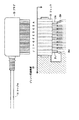
すなわち、図5にも示すように、ジャック31は携帯電話機30のプリント配線基板39に取り付けられているが、このとき、ジャック31の端子A〜Jは、その一部が延長されてリード線31A〜31Jとされ、このリード線31A〜31Jがプリント配線基板39の配線パターン39A〜39Jにそれぞれハンダ付けされている。この場合、端子Jのリード線31Jがハンダ付けされている配線パターン39Jが接地パターンである。
That is, as shown in FIG. 5, the jack 31 is attached to the printed
しかし、ジャック31は、全体が偏平で、10mm×5mm程度の大きさであり、したがって、端子A〜Jのリード線31A〜31Jはかなり細いものとなっている。また、同軸ケーブル14Aからの放送波信号は端子Aに供給されるが、この端子Aは接地用端子Jから離れているので、アンテナに対する接地の効果が弱くなる。さらに、地上波デジタルテレビ放送は、UHF帯のうちの周波数470MHz〜770MHzの帯域が割り当てられている。
However, the jack 31 as a whole is flat and has a size of about 10 mm × 5 mm. Therefore, the
これらの結果、端子Jおよびリード線31Jが、地上波デジタルテレビ放送の放送波信号に対してインダクタンス性のインピーダンスを示すようになり、このインピーダンス分によりその放送波信号に伝送損失を生じてしまう。すなわち、受信感度が低下してしまう。
As a result, the terminal J and the
この場合、残る端子B、G〜Iも端子Jと同様に、同軸ケーブル14Aの接地に使用すれば、インピーダンスを減らすことができ、伝送損失を低減することができる。しかし、プラグ15およびジャック31は、その規格上、端子B、G〜Iをかってな用途に使用することはできない。
In this case, if the remaining terminals B and G to I are used for grounding the
この発明は、このような問題点を解決しようとするものである。 The present invention is intended to solve such problems.
この発明においては、
イヤホンをイヤホンアンテナとして機能させる受信機において、
上記イヤホンのイヤホンケーブルが受信した放送波信号が供給されてオーディオ信号を出力する受信回路と、
イヤホンプラグが差し込まれるイヤホンジャックと、
上記イヤホンがステレオ用であるかモノラル用であるかを検出する第1の検出回路と、
上記イヤホンが接続されているか否かを検出する第2の検出回路と
を有し、
上記イヤホンジャックは、
アンテナ用の端子と、
左および右チャンネルの各オーディオ用端子と、
第1および第2の検出用端子と、
接地用端子と
を有し、
上記アンテナ用の端子は、カップリングコンデンサを通じて上記受信回路のアンテナ入力端に接続され、
上記左および右チャンネルの各オーディオ用端子は、第1および第2の高周波チョークコイルを通じて上記受信回路のオーディオ出力端にそれぞれ接続され、
上記第1および第2の検出用端子は、第3および第4の高周波チョークコイルを通じて上記第1および第2の検出回路の入力端にそれぞれ接続されるとともに、
上記第1および第2の検出用端子の少なくとも一方がバイパスコンデンサを通じて接地に接続され、
上記接地用端子が接地に接続され、
上記イヤホンケーブルが受信した放送波信号が、上記アンテナ用の端子および上記カップリングコンデンサを通じて上記受信回路に供給されるとともに、
上記第1および第2の検出用端子の少なくとも一方が上記バイパスコンデンサを通じて高周波的に接地される
ようにした受信機
とするものである。
In this invention,
In the receiver that makes the earphone function as an earphone antenna,
A receiving circuit that receives the broadcast wave signal received by the earphone cable of the earphone and outputs an audio signal;
An earphone jack into which the earphone plug is inserted;
A first detection circuit for detecting whether the earphone is for stereo or monaural;
A second detection circuit for detecting whether or not the earphone is connected,
The above earphone jack
A terminal for the antenna;
Left and right channel audio connectors,
First and second detection terminals;
A grounding terminal, and
The terminal for the antenna is connected to the antenna input end of the receiving circuit through a coupling capacitor,
The audio terminals for the left and right channels are connected to the audio output terminals of the receiving circuit through first and second high frequency choke coils,
The first and second detection terminals are connected to input terminals of the first and second detection circuits through third and fourth high-frequency choke coils, respectively.
At least one of the first and second detection terminals is connected to ground through a bypass capacitor;
The grounding terminal is connected to ground,
The broadcast wave signal received by the earphone cable is supplied to the receiving circuit through the antenna terminal and the coupling capacitor,
The receiver is configured such that at least one of the first and second detection terminals is grounded in high frequency through the bypass capacitor.
この発明によれば、伝送損失が大幅に減少し、受信感度の低下を抑えることができる。また、伝送損失が少ないだけでなく、周波数にかかわらずほぼ一定となって受信感度にむらを生じることがない。さらに、イヤホンプラグおよびイヤホンジャックのよけいな端子を使用する必要もない。 According to the present invention, transmission loss is greatly reduced, and a decrease in reception sensitivity can be suppressed. Further, not only the transmission loss is small, but also the reception sensitivity becomes non-uniform because it is almost constant regardless of the frequency. Furthermore, it is not necessary to use the extra terminals of the earphone plug and the earphone jack.
図1は、この発明を、携帯電話機に内蔵した受信回路に適用した場合の一形態を示す。そして、図1においては、ステレオイヤホン10およびモノラルイヤホン20が、図3のものに比べ、簡略化されている場合である。
FIG. 1 shows an embodiment in which the present invention is applied to a receiving circuit built in a mobile phone. FIG. 1 shows a case where the
すなわち、ステレオイヤホン10は、左および右チャンネルのイヤホンユニット11L、11Rと、中間ユニット13との間が、ケーブル12L、12Rにより接続され、中間ユニット13とイヤホンプラグ15との間がケーブル14により接続されている。
That is, in the
この場合、ケーブル12L、12Rはそれぞれ2芯ケーブルとされるが、このケーブル12L、12Rが放送受信用のアンテナの実効部分として作用するものである。また、ケーブル14は、3本の信号導線14C、14L、14Rを有し、これら信号導線14C〜14Rを中心導線とし、シールド外皮14Sが覆うことにより、全体が同軸ケーブルに構成されている。そして、中間ユニット13において、ケーブル12Lの一方と、ケーブル12Rの一方とが共通に接続されるとともに、信号導線14Cの一端に接続され、ケーブル12L、ケーブル12Rの各他方が信号導線14L、14Rの各一端に接続されている。なお、シールド外皮14Sの一端はどこにも接続されない。
In this case, the
さらに、イヤホンプラグ15は、上述のように10個の端子A〜Jを有するが、カップリングコンデンサC11、C12と、例えばフェライトビーズにより構成された高周波チョークコイルL13とを内蔵している。そして、このプラグ15の内部において、信号導線14C、14R、14Lの各他端が、端子A、D、Eに接続され、シールド外皮14Sの他端が端子Jに接続されている。また、端子Aと端子Dとの間に、コンデンサC12が接続され、端子Dと端子Eとの間に、コンデンサC11が接続され、端子Aと端子Cとの間に、高周波チョークコイルL13が接続されている。さらに、端子Fと端子Jとが接続されるとともに、イヤホン10がステレオ用なので、端子Cと端子Jとが接続されている。
Further, the
また、モノラルイヤホン20もステレオイヤホン10の右チャンネルと同様に構成されている。ただし、プラグ15においては、端子Fと端子Jとが接続されるが、イヤホン20はモノラル用なので、端子Cと端子Jとは接続されていない。
The
一方、携帯電話機30は、イヤホンジャック31を有するとともに、さらに、FM放送および地上波デジタルテレビ放送を受信する受信回路32と、マイクロコンピュータにより構成されたシステムコントロール回路33とを有する。この場合、受信回路32は、システムコントロール回路33により制御され、FM放送および地上波デジタルテレビ放送の受信バンドを選択できるとともに、その選択した受信バンドにおける任意の放送(チャンネル)を選局できるものである。そして、受信回路32は、ステレオあるいはモノラルのオーディオ信号L、Rを出力するとともに、テレビ放送の選択時には、その映像をディスプレイ(図示せず)に表示するものである。
On the other hand, the
このため、受信回路32とシステムコントロール回路33との間で、各種のデータおよびコマンドがやりとりされる。また、システムコントロール回路33には、バンド切り換えスイッチや選局スイッチなど各種の操作スイッチ34が接続されている。
For this reason, various data and commands are exchanged between the receiving
そして、ジャック31のアンテナ用端子Aが、カップリングコンデンサC35を通じて受信回路32のアンテナ入力端に接続されるとともに、その端子Aと接地との間に高周波チョークコイルL35が接続される。また、受信回路32の左および右チャンネルのオーディオ出力端が、高周波チョークコイルL31、L32を通じてジャック31のオーディオ用端子E、Dに接続される。
The antenna terminal A of the jack 31 is connected to the antenna input terminal of the receiving
さらに、検出回路35、36が設けられ、ジャック31の検出用端子C、Fが、高周波チョークコイルL33、L34を通じて検出回路35、36の入力端に接続されるとともに、その検出出力がシステムコントロール回路33に供給される。また、ジャック31の端子C、Fと、接地との間に、バイパスコンデンサC33、C34が接続される。さらに、ジャック31の端子Jが接地に接続される。なお、検出回路35、36の入力端は、図示はしないがプルアップされているものとする。
Further,
このような構成によれば、ジャック31にステレオイヤホン10のプラグ15が差し込まれている場合には、ジャック31の端子Cは、プラグ15の端子C、Jを通じて接地されるので、その直流電位は“L”である。しかし、ジャック31にモノラルイヤホン20のプラグ15が差し込まれている場合には、ジャック31の端子Cは開放されるので、その直流電位は“H”である。
According to such a configuration, when the
そして、このジャック31の端子Cの直流電位が、高周波チョークコイルL33を通じて検出回路35により検出され、その検出出力がシステムコントロール回路33に供給される。したがって、システムコントロール回路33は、ジャック31にステレオイヤホン10が接続されているのかモノラルイヤホン20が接続されているのかを知ることができる。この結果、受信回路32から出力されるオーディオ信号L、Rをステレオあるいはモノラルに切り換えることができる。
The DC potential at the terminal C of the jack 31 is detected by the
そして、ジャック31にステレオイヤホン10のプラグ15が差し込まれている場合には、FM放送および地上波デジタルテレビ放送の放送波が、ケーブル12L、12Rにより受信され、この受信された放送波信号が、ケーブル12L、12R→信号導線14C、14L、14R→(およびコンデンサC11、C12→)プラグ15の端子A→ジャック31の端子A→コンデンサC35の信号ラインを通じて受信回路32に供給される。
When the
また、同軸ケーブル14のシールド外皮14Sが、プラグ15の端子J→ジャック31の端子Jのラインを通じて接地されるとともに、プラグ15の端子C、F→ジャック31の端子C、F→コンデンサC33、C34のラインを通じて接地される。なお、このとき、ジャック31の端子E、Dには、高周波チョークコイルL31、L32が接続されているので、ケーブル12L、12Rの受信した放送波信号がジャック31の端子E、Dから受信回路32にリークすることはない。
Further, the shield outer sheath 14S of the
この結果、操作スイッチ34を操作すると、FM放送あるいは地上波デジタルテレビ放送が選択されるとともに、チャンネルが選局され、受信回路32からは目的とする放送のオーディオ信号L、Rが出力される。
As a result, when the
そして、このオーディオ信号L、Rが、高周波チョークコイルL31、L32→ジャック31の端子E、D→プラグ15の端子E、D→信号導線14L、14R→ケーブル12L、12Rのラインを通じてイヤホンユニット11L、11Rに供給される。
The audio signals L and R are sent from the high frequency choke coils L31 and L32 to the jack E terminal E, D to the plug E terminal E, D to the
このとき、イヤホンユニット11L、11R→ケーブル12L、12R→信号導線14C→高周波チョークコイルL13→プラグ15の端子J→ジャック31の端子J→接地のラインが、リターンパスとなる。さらに、イヤホンユニット11L、11R→ケーブル12L、12R→信号導線14C→プラグ15の端子A→ジャック31の端子A→高周波チョークコイルL35→接地のラインもリターンパスとなる。
At this time, the
したがって、イヤホン10により放送をステレオで聴取することができる。また、このとき、地上波デジタルテレビ放送を受信しているのであれば、その映像が受信回路32のディスプレイに表示される。
Therefore, the
一方、ジャック31にモノラルイヤホン20のプラグ15が差し込まれた場合には、FM放送および地上波デジタルテレビ放送の放送波がケーブル12Rにより受信され、この受信された放送波信号が、ケーブル12R→信号導線14C→プラグ15の端子A→ジャック31の端子A→コンデンサC35の信号ラインを通じて受信回路32に供給される。したがって、受信回路32からは目的とする放送のモノラルオーディオ信号が出力される。
On the other hand, when the
そして、このオーディオ信号が、高周波チョークコイルL32→ジャック31の端子D→プラグ15の端子D→信号導線14R→ケーブル12Rのラインを通じてイヤホンユニット11Rに供給される。
This audio signal is supplied to the
このとき、イヤホンユニット11R→ケーブル12R→信号導線14C→高周波チョークコイルL13→プラグ15の端子J→ジャック31の端子J→接地のラインが、リターンパスとなる。さらに、イヤホンユニット11R→ケーブル12R→信号導線14C→プラグ15の端子A→ジャック31の端子A→高周波チョークコイルL35→接地のラインもリターンパスとなる。
At this time, the
したがって、イヤホン20により放送をモノラルで聴取することができる。また、このとき、地上波デジタルテレビ放送を受信しているのであれば、その映像が受信回路32のディスプレイに表示される。
Therefore, the
なお、ジャック31にイヤホン10、20のプラグ15が差し込まれていない場合には、ジャック31の端子Fは開放されているので、その直流電位は“H”である。しかし、ジャック31にプラグ15が差し込まれている場合には、ジャック31の端子Fは、プラグ15の端子F、Jを通じて接地されるので、その直流電位は“L”である。
When the
そして、このジャック31の端子Fの直流電位が、高周波チョークコイルL34を通じて検出回路36により検出され、その検出出力がシステムコントロール回路33に供給される。したがって、システムコントロール回路33は、ジャック31にプラグ15が差し込まれているか否かを知ることができる。
The DC potential at the terminal F of the jack 31 is detected by the
こうして、上述のイヤホン10、20および携帯電話機30によれば、イヤホン10、20を受信アンテナとして使用してFM放送および地上波デジタルテレビ放送を視聴することができる。
Thus, according to the above-described
そして、その場合、同軸ケーブル14のシールド外皮14Sは、プラグ15の端子J→ジャック31の端子Jのラインを通じて接地されるだけでなく、プラグ15の端子C、F→ジャック31の端子C、F→コンデンサC33、C34のラインも通じて高周波的に接地される。また、同軸ケーブル14から放送波信号が供給される端子Aに近接した端子Cが接地されている。これらの結果、同軸ケーブル14のシールド外皮14Sと、接地との間のインピーダンスが小さくなり、放送波信号に対する伝送損失が小さくなる。また、これにより受信感度の低下を抑えることができる。
In this case, the shield outer sheath 14S of the
さらに、図3に示すイヤホン10、20であっても、イヤホンアンテナとして使用することができる。
Furthermore, even the
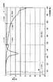
図2は、この発明を適用した場合と、適用しない場合とにおける伝送損失(受信感度)の測定結果を示す。ここで、特性Aは、この発明を適用した場合であり、コンデンサC33、C34の容量をそれぞれ10pFとした場合である。また、特性Bは、この発明を適用しない場合であり、コンデンサC33、C34を接続しない場合である。なお、第13チャンネルの下端(周波数470MHz)および第62チャンネルの上端(周波数770MHz)における損失は、図中に示すとおりである。 FIG. 2 shows measurement results of transmission loss (reception sensitivity) when the present invention is applied and when it is not applied. Here, the characteristic A is the case where the present invention is applied, and the case where the capacitances of the capacitors C33 and C34 are 10 pF. Characteristic B is the case where the present invention is not applied, and the case where the capacitors C33 and C34 are not connected. The losses at the lower end of the 13th channel (frequency 470 MHz) and at the upper end of the 62nd channel (frequency 770 MHz) are as shown in the figure.
この測定結果からも明らかなように、この発明によれば、伝送損失が大幅に減少しているので、受信感度の低下を抑えることができる。また、伝送損失が少ないだけでなく周波数にかかわらずほぼ一定となっているので、受信感度にむらを生じることがなく、例えばAGCを有効にかけることができる。さらに、端子B、G〜Iを使用する必要もない。また、コンデンサC33、C34を接続するだけでよく、部品点数を少なくできるとともに、実装面積を小さくすることができる。 As is apparent from the measurement results, according to the present invention, the transmission loss is greatly reduced, so that it is possible to suppress a decrease in reception sensitivity. Further, since the transmission loss is not only small but is almost constant regardless of the frequency, there is no unevenness in reception sensitivity and, for example, AGC can be effectively applied. Furthermore, it is not necessary to use the terminals B and G to I. Further, it is only necessary to connect the capacitors C33 and C34, so that the number of parts can be reduced and the mounting area can be reduced.
なお、特性Aには、周波数fr(≒334MHz)にディップを生じているが、これは、同軸ケーブル14と携帯電話機30の接地との間のインダクタンス分と、コンデンサC33、C34との共振により生じたものである。したがって、コンデンサC33、C34の値を変更すれば、この共振周波数(ディップ周波数)frを変更することができる。
In the characteristic A, a dip occurs at the frequency fr (≈334 MHz), which is caused by the resonance between the inductance between the
ただし、その場合、コンデンサC33、C34の値を小さくすると、その共振周波数frが地上波デジタルテレビ放送の周波数帯域(第13チャンネル〜第62チャンネル)に近づいてその低域側における感度の低下を招いてしまう。しかし、大きくすると、共振周波数frがFM放送の周波数帯域(76MHz〜90MHz)に近づいてその高域側における感度の低下を招いてしまう。また、同軸ケーブル14と携帯電話機30の接地との間のインダクタンス分は、イヤホンジャック31のリード線31C、31F、31Jの形状(長さや幅)やプリント配線基板39への実装方法によっても異なった値となる。
However, in this case, if the values of the capacitors C33 and C34 are reduced, the resonance frequency fr approaches the frequency band (
以上を考慮すると、FM放送および地上波デジタルテレビ放送を受信する場合、コンデンサC33、C34の値は、それぞれ5pF〜30pFが適切である。 Considering the above, when receiving FM broadcast and terrestrial digital television broadcast, the values of capacitors C33 and C34 are appropriately 5 pF to 30 pF.
こうして、上述の回路によれば、イヤホンアンテナの受信した放送波信号に対する伝送損失を、大幅に減少させることができ、受信感度の低下を抑えることができる。また、伝送損失が少ないだけでなく周波数にかかわらずほぼ一定とすることができ、受信感度にむらを生じることがない。さらに、端子B、G〜Iを使用する必要もない。 Thus, according to the above-described circuit, transmission loss with respect to the broadcast wave signal received by the earphone antenna can be greatly reduced, and a decrease in reception sensitivity can be suppressed. Further, not only the transmission loss is small, but also it can be made almost constant regardless of the frequency, and the reception sensitivity is not uneven. Furthermore, it is not necessary to use the terminals B and G to I.
なお、上述においては、携帯電話機にFM放送および地上波デジタルテレビ放送の受信回路を内蔵させた場合であるが、UHF帯の放送、特に地上波デジタルテレビ放送の受信する場合であれば、専用の受信機にもこの発明を適用することができ、その場合、イヤホンアンテナを、図1に示したものをそのまま使用することができる。また、上述において、高周波チョークコイルL13、L35をどちらか一方だけとすることもでき、コンデンサC33、C34もどちらか一方だけとすることもできる。 In the above description, the reception circuit for FM broadcast and terrestrial digital TV broadcast is built in the mobile phone. However, if the receiver receives UHF band broadcast, especially terrestrial digital TV broadcast, a dedicated mobile phone is used. The present invention can also be applied to a receiver. In that case, the earphone antenna shown in FIG. 1 can be used as it is. In the above description, only one of the high frequency choke coils L13 and L35 can be used, and only one of the capacitors C33 and C34 can be used.
〔略語の一覧〕
AGC:Automatic Gain Control
FM :Frequency Modulation
UHF:Ultra High Frequency
[List of abbreviations]
AGC: Automatic Gain Control
FM: Frequency Modulation
UHF: Ultra High Frequency
10…ステレオイヤホン、11Lおよび11R…イヤホンユニット、12Lおよび12R…ケーブル、13…中間ユニット、14…同軸ケーブル、15…イヤホンプラグ、20…モノラルイヤホン、30…携帯電話機、31…イヤホンジャック、32…受信回路、33…システムコントロール回路、35および36…検出回路
DESCRIPTION OF
Claims (5)
上記イヤホンのイヤホンケーブルが受信した放送波信号が供給されてオーディオ信号を出力する受信回路と、
イヤホンプラグが差し込まれるイヤホンジャックと、
上記イヤホンがステレオ用であるかモノラル用であるかを検出する第1の検出回路と、
上記イヤホンが接続されているか否かを検出する第2の検出回路と
を有し、
上記イヤホンジャックは、
アンテナ用の端子と、
左および右チャンネルの各オーディオ用端子と、
第1および第2の検出用端子と、
接地用端子と
を有し、
上記アンテナ用の端子は、カップリングコンデンサを通じて上記受信回路のアンテナ入力端に接続され、
上記左および右チャンネルの各オーディオ用端子は、第1および第2の高周波チョークコイルを通じて上記受信回路のオーディオ出力端にそれぞれ接続され、
上記第1および第2の検出用端子は、第3および第4の高周波チョークコイルを通じて上記第1および第2の検出回路の入力端にそれぞれ接続されるとともに、
上記第1および第2の検出用端子の少なくとも一方がバイパスコンデンサを通じて接地に接続され、
上記接地用端子が接地に接続され、
上記イヤホンケーブルが受信した放送波信号が、上記アンテナ用の端子および上記カップリングコンデンサを通じて上記受信回路に供給されるとともに、
上記第1および第2の検出用端子の少なくとも一方が上記バイパスコンデンサを通じて高周波的に接地される
ようにした受信機。 In the receiver that makes the earphone function as an earphone antenna,
A receiving circuit that receives the broadcast wave signal received by the earphone cable of the earphone and outputs an audio signal;
An earphone jack into which the earphone plug is inserted;
A first detection circuit for detecting whether the earphone is for stereo or monaural;
A second detection circuit for detecting whether or not the earphone is connected,
The above earphone jack
A terminal for the antenna;
Left and right channel audio connectors,
First and second detection terminals;
A grounding terminal, and
The terminal for the antenna is connected to the antenna input end of the receiving circuit through a coupling capacitor,
The audio terminals for the left and right channels are connected to the audio output terminals of the receiving circuit through first and second high frequency choke coils,
The first and second detection terminals are connected to input terminals of the first and second detection circuits through third and fourth high-frequency choke coils, respectively.
At least one of the first and second detection terminals is connected to ground through a bypass capacitor;
The grounding terminal is connected to ground,
A broadcast wave signal received by the earphone cable is supplied to the receiving circuit through the antenna terminal and the coupling capacitor,
A receiver in which at least one of the first and second detection terminals is grounded in high frequency through the bypass capacitor.
上記アンテナ用の端子が第5の高周波チョークコイルを通じて接地に接続されている
ようにした受信機。 The receiver of claim 1,
A receiver in which the antenna terminal is connected to the ground through a fifth high-frequency choke coil.
上記放送波信号が、FM放送および地上波デジタルテレビ放送の受信信号である
ようにした受信機。 The receiver of claim 1,
A receiver in which the broadcast wave signal is a reception signal of FM broadcast and terrestrial digital television broadcast.
受信感度のディップが、上記FM放送の周波数帯および上記地上波デジタルテレビ放送の周波数帯の間に位置するように、上記バイパスコンデンサの値が選択されている
ようにした受信機。 The receiver according to claim 3,
A receiver in which the value of the bypass capacitor is selected so that a dip in reception sensitivity is located between the frequency band of the FM broadcast and the frequency band of the terrestrial digital television broadcast.
アンテナ用の端子と、
左および右チャンネルの各オーディオ用端子と、
イヤホンがステレオ用であるかモノラル用であるかを検出するための第1の検出用端子と、
上記イヤホンが接続されているか否かを検出するための第2の検出用端子と、
接地用端子と
を有し、
上記イヤホンがステレオイヤホンのときには、上記第1の検出用端子と、上記第2の検出用端子と、上記接地用端子とが接続され、
上記イヤホンがモノラルイヤホンのときには、上記第2の検出用端子と、上記接地用端子とが接続されている場合に、
上記イヤホンをイヤホンアンテナとして機能させる受信機において、
上記イヤホンのイヤホンケーブルが受信した放送波信号が供給されてオーディオ信号を出力する受信回路と、
上記イヤホンプラグが差し込まれるイヤホンジャックと、
第1および第2の検出回路と
を有し、
上記イヤホンジャックは、上記イヤホンプラグの各端子に対応して、
アンテナ用の端子と、
左および右チャンネルの各オーディオ用端子と、
第1および第2の検出用端子と、
接地用端子と
を有し、
上記イヤホンジャックの端子のうち、
上記アンテナ用の端子は、カップリングコンデンサを通じて上記受信回路のアンテナ入力端に接続され、
上記左および右チャンネルの各オーディオ用端子は、第1および第2の高周波チョークコイルを通じて上記受信回路のオーディオ出力端にそれぞれ接続され、
上記第1および第2の検出用端子は、第3および第4の高周波チョークコイルを通じて上記第1および第2の検出回路の入力端にそれぞれ接続されるとともに、
上記第1および第2の検出用端子の少なくとも一方がバイパスコンデンサを通じて接地に接続され、
上記接地用端子が接地に接続され、
上記イヤホンケーブルが受信した放送波信号が、上記アンテナ用の端子および上記カップリングコンデンサを通じて上記受信回路に供給されるとともに、
上記第1および第2の検出用端子の少なくとも一方が上記バイパスコンデンサを通じて高周波的に接地される
ようにした受信機。 Earphone plug
A terminal for the antenna;
Left and right channel audio connectors,
A first detection terminal for detecting whether the earphone is for stereo or monaural;
A second detection terminal for detecting whether or not the earphone is connected;
A grounding terminal, and
When the earphone is a stereo earphone, the first detection terminal, the second detection terminal, and the ground terminal are connected,
When the earphone is a monaural earphone, when the second detection terminal and the grounding terminal are connected,
In the receiver that functions the earphone as an earphone antenna,
A receiving circuit that receives the broadcast wave signal received by the earphone cable of the earphone and outputs an audio signal;
An earphone jack into which the earphone plug is inserted;
A first detection circuit and a second detection circuit;
The earphone jack corresponds to each terminal of the earphone plug,
A terminal for the antenna;
Left and right channel audio connectors,
First and second detection terminals;
A grounding terminal, and
Of the above earphone jack terminals,
The terminal for the antenna is connected to the antenna input end of the receiving circuit through a coupling capacitor,
The audio terminals for the left and right channels are connected to the audio output terminals of the receiving circuit through first and second high frequency choke coils,
The first and second detection terminals are connected to input terminals of the first and second detection circuits through third and fourth high-frequency choke coils, respectively.
At least one of the first and second detection terminals is connected to ground through a bypass capacitor;
The grounding terminal is connected to ground,
A broadcast wave signal received by the earphone cable is supplied to the receiving circuit through the antenna terminal and the coupling capacitor,
A receiver in which at least one of the first and second detection terminals is grounded in high frequency through the bypass capacitor.
Priority Applications (4)
| Application Number | Priority Date | Filing Date | Title |
|---|---|---|---|
| JP2005336477A JP4569449B2 (en) | 2005-11-22 | 2005-11-22 | Receiving machine |
| US11/599,354 US8243958B2 (en) | 2005-11-22 | 2006-11-15 | Receiver |
| EP06124221A EP1788712A3 (en) | 2005-11-22 | 2006-11-16 | Radio receiver |
| CN2006101624347A CN1972009B (en) | 2005-11-22 | 2006-11-22 | Receiver |
Applications Claiming Priority (1)
| Application Number | Priority Date | Filing Date | Title |
|---|---|---|---|
| JP2005336477A JP4569449B2 (en) | 2005-11-22 | 2005-11-22 | Receiving machine |
Publications (2)
| Publication Number | Publication Date |
|---|---|
| JP2007142987A true JP2007142987A (en) | 2007-06-07 |
| JP4569449B2 JP4569449B2 (en) | 2010-10-27 |
Family
ID=37775212
Family Applications (1)
| Application Number | Title | Priority Date | Filing Date |
|---|---|---|---|
| JP2005336477A Expired - Fee Related JP4569449B2 (en) | 2005-11-22 | 2005-11-22 | Receiving machine |
Country Status (4)
| Country | Link |
|---|---|
| US (1) | US8243958B2 (en) |
| EP (1) | EP1788712A3 (en) |
| JP (1) | JP4569449B2 (en) |
| CN (1) | CN1972009B (en) |
Cited By (3)
| Publication number | Priority date | Publication date | Assignee | Title |
|---|---|---|---|---|
| JP2008236113A (en) * | 2007-03-19 | 2008-10-02 | Sony Corp | Receiver and antenna |
| JP2010068169A (en) * | 2008-09-10 | 2010-03-25 | Sony Corp | Receiver, antenna, and relay cable |
| JP2013183452A (en) * | 2012-02-29 | 2013-09-12 | Htc Corp | Headset, circuit structure of mobile apparatus, and mobile apparatus |
Families Citing this family (12)
| Publication number | Priority date | Publication date | Assignee | Title |
|---|---|---|---|---|
| US8428670B2 (en) * | 2007-04-11 | 2013-04-23 | Sony Corporation | Reception device, antenna, and junction cable |
| CN101330776B (en) * | 2007-06-21 | 2012-02-29 | 上海风格信息技术有限公司 | Method for reverse phase detection of audio signal left and right acoustic channels |
| US8032090B2 (en) * | 2007-06-29 | 2011-10-04 | Silicon Laboratories Inc. | Antenna for use in portable applications |
| FR2930093A1 (en) * | 2008-04-10 | 2009-10-16 | Somfy Sas | TRANSMITTER TYPE DEVICE AND / OR RECEIVER OF RADIO SIGNALS |
| KR100999856B1 (en) * | 2008-04-22 | 2010-12-13 | 삼성전자주식회사 | Headset improving antenna efficiency by using ferrite bead |
| JP5347608B2 (en) | 2009-03-17 | 2013-11-20 | ソニー株式会社 | Receiver |
| JP5444786B2 (en) * | 2009-03-30 | 2014-03-19 | ソニー株式会社 | Receiver |
| CN101951268A (en) * | 2010-07-23 | 2011-01-19 | 惠州Tcl移动通信有限公司 | Method and device for improving performance of radio antenna |
| US10045118B2 (en) | 2012-07-02 | 2018-08-07 | Fox Digital Enterprises, Inc. | Integrated antenna for receiving television broadcasts |
| US8903102B2 (en) * | 2012-07-02 | 2014-12-02 | Fox Digital Enterprises, Inc. | Integrated earbud antenna for receiving television broadcasts |
| CN104469615A (en) * | 2014-12-15 | 2015-03-25 | 上海华勤通讯技术有限公司 | Terminal device and earphone circuit thereof |
| US20190110119A1 (en) * | 2016-03-29 | 2019-04-11 | Sony Corporation | Receiver and rf signal supply apparatus |
Citations (8)
| Publication number | Priority date | Publication date | Assignee | Title |
|---|---|---|---|---|
| JPH08163686A (en) * | 1994-11-30 | 1996-06-21 | Sony Corp | Input/output circuit for audio equipment |
| JPH1079997A (en) * | 1996-09-05 | 1998-03-24 | Sony Corp | Connecting device of information equipment and connecting device of stereo sound/video device |
| JP2004328419A (en) * | 2003-04-25 | 2004-11-18 | Sony Corp | Acoustic signal input and output unit, switching method of input and output circuit |
| JP2005064742A (en) * | 2003-08-08 | 2005-03-10 | Sony Corp | Earphone antenna, and portable radio set equipped with the same |
| JP2005204058A (en) * | 2004-01-15 | 2005-07-28 | Fujitsu Ten Ltd | Receiving system |
| JP2005354275A (en) * | 2004-06-09 | 2005-12-22 | Hosiden Corp | Earphone microphone |
| JP2006287720A (en) * | 2005-04-01 | 2006-10-19 | Hosiden Corp | Earphone antenna |
| JP2006345307A (en) * | 2005-06-09 | 2006-12-21 | Toshiba Corp | Linear antenna |
Family Cites Families (11)
| Publication number | Priority date | Publication date | Assignee | Title |
|---|---|---|---|---|
| JPH11177250A (en) * | 1997-12-08 | 1999-07-02 | Sony Corp | Electronic apparatus |
| MXPA00012847A (en) * | 2000-01-07 | 2003-04-25 | Motorola Inc | Radio broadcasting receiver has control unit that switches. |
| JP2003163529A (en) | 2001-11-28 | 2003-06-06 | Alps Electric Co Ltd | Headphone serving as diversity antenna |
| JP4363865B2 (en) | 2003-02-28 | 2009-11-11 | ソニー株式会社 | Earphone antenna and radio |
| JP4003671B2 (en) * | 2003-03-07 | 2007-11-07 | ソニー株式会社 | Earphone antenna and radio equipped with the same |
| JP3880571B2 (en) * | 2003-10-29 | 2007-02-14 | Necアクセステクニカ株式会社 | Antenna device |
| JP4026648B2 (en) * | 2004-04-19 | 2007-12-26 | ソニー株式会社 | Earphone antenna and portable radio equipped with the earphone antenna |
| JP3933148B2 (en) * | 2004-06-04 | 2007-06-20 | ソニー株式会社 | Earphone antenna and portable radio equipped with the earphone antenna |
| TWI277355B (en) * | 2004-07-08 | 2007-03-21 | Sony Corp | Earphone antenna connecting device and portable wireless device |
| JP4023500B2 (en) * | 2004-08-03 | 2007-12-19 | ソニー株式会社 | Earphone antenna |
| JP4123262B2 (en) * | 2005-10-07 | 2008-07-23 | ソニー株式会社 | Earphone antenna |
-
2005
- 2005-11-22 JP JP2005336477A patent/JP4569449B2/en not_active Expired - Fee Related
-
2006
- 2006-11-15 US US11/599,354 patent/US8243958B2/en not_active Expired - Fee Related
- 2006-11-16 EP EP06124221A patent/EP1788712A3/en not_active Withdrawn
- 2006-11-22 CN CN2006101624347A patent/CN1972009B/en not_active Expired - Fee Related
Patent Citations (8)
| Publication number | Priority date | Publication date | Assignee | Title |
|---|---|---|---|---|
| JPH08163686A (en) * | 1994-11-30 | 1996-06-21 | Sony Corp | Input/output circuit for audio equipment |
| JPH1079997A (en) * | 1996-09-05 | 1998-03-24 | Sony Corp | Connecting device of information equipment and connecting device of stereo sound/video device |
| JP2004328419A (en) * | 2003-04-25 | 2004-11-18 | Sony Corp | Acoustic signal input and output unit, switching method of input and output circuit |
| JP2005064742A (en) * | 2003-08-08 | 2005-03-10 | Sony Corp | Earphone antenna, and portable radio set equipped with the same |
| JP2005204058A (en) * | 2004-01-15 | 2005-07-28 | Fujitsu Ten Ltd | Receiving system |
| JP2005354275A (en) * | 2004-06-09 | 2005-12-22 | Hosiden Corp | Earphone microphone |
| JP2006287720A (en) * | 2005-04-01 | 2006-10-19 | Hosiden Corp | Earphone antenna |
| JP2006345307A (en) * | 2005-06-09 | 2006-12-21 | Toshiba Corp | Linear antenna |
Cited By (4)
| Publication number | Priority date | Publication date | Assignee | Title |
|---|---|---|---|---|
| JP2008236113A (en) * | 2007-03-19 | 2008-10-02 | Sony Corp | Receiver and antenna |
| JP2010068169A (en) * | 2008-09-10 | 2010-03-25 | Sony Corp | Receiver, antenna, and relay cable |
| JP2013183452A (en) * | 2012-02-29 | 2013-09-12 | Htc Corp | Headset, circuit structure of mobile apparatus, and mobile apparatus |
| US9509044B2 (en) | 2012-02-29 | 2016-11-29 | Htc Corporation | Headset, circuit structure of mobile apparatus, and mobile apparatus |
Also Published As
| Publication number | Publication date |
|---|---|
| US20070127741A1 (en) | 2007-06-07 |
| US8243958B2 (en) | 2012-08-14 |
| EP1788712A3 (en) | 2008-12-03 |
| CN1972009A (en) | 2007-05-30 |
| JP4569449B2 (en) | 2010-10-27 |
| CN1972009B (en) | 2012-06-20 |
| EP1788712A2 (en) | 2007-05-23 |
Similar Documents
| Publication | Publication Date | Title |
|---|---|---|
| JP4569449B2 (en) | Receiving machine | |
| KR101105483B1 (en) | Earphone antenna and portable radio equipment provided with earphone antenna | |
| KR101050046B1 (en) | Portable radio with earphone antenna and earphone antenna | |
| US7840242B2 (en) | Earphone antenna | |
| US8237623B2 (en) | Headset antenna and connector for the same | |
| US20070032130A1 (en) | Earphone antenna connecting device and portable wireless device | |
| US8428670B2 (en) | Reception device, antenna, and junction cable | |
| CN100452531C (en) | Earphone antenna and portable radio equipment provided with earphone antenna | |
| JP5609206B2 (en) | Connection device, antenna device and receiving device | |
| JP5092942B2 (en) | Receiver, antenna and relay cable | |
| KR20110019841A (en) | Method and apparatus for improving audio channel cross talk in portable terminal | |
| JP5589496B2 (en) | Connection device and receiver | |
| JP4973529B2 (en) | Receiving system, receiving device and relay cable | |
| KR100498676B1 (en) | A earphone antenna for receiving high frequency broadcasting signal | |
| JP2015092734A (en) | Antenna device, and receiver | |
| JP4924171B2 (en) | Receiver, antenna and relay cable | |
| JP2016189603A (en) | Reception device | |
| CN102163765A (en) | Antenna device and receiving device | |
| JP2010028254A (en) | Receiver, antenna and relay cable | |
| JP2010087756A (en) | On-vehicle antenna device and on-vehicle receiver |
Legal Events
| Date | Code | Title | Description |
|---|---|---|---|
| A621 | Written request for application examination |
Free format text: JAPANESE INTERMEDIATE CODE: A621 Effective date: 20081105 |
|
| RD02 | Notification of acceptance of power of attorney |
Free format text: JAPANESE INTERMEDIATE CODE: A7422 Effective date: 20090807 |
|
| RD04 | Notification of resignation of power of attorney |
Free format text: JAPANESE INTERMEDIATE CODE: A7424 Effective date: 20091002 |
|
| TRDD | Decision of grant or rejection written | ||
| A01 | Written decision to grant a patent or to grant a registration (utility model) |
Free format text: JAPANESE INTERMEDIATE CODE: A01 Effective date: 20100713 |
|
| A01 | Written decision to grant a patent or to grant a registration (utility model) |
Free format text: JAPANESE INTERMEDIATE CODE: A01 |
|
| A61 | First payment of annual fees (during grant procedure) |
Free format text: JAPANESE INTERMEDIATE CODE: A61 Effective date: 20100726 |
|
| FPAY | Renewal fee payment (event date is renewal date of database) |
Free format text: PAYMENT UNTIL: 20130820 Year of fee payment: 3 |
|
| R151 | Written notification of patent or utility model registration |
Ref document number: 4569449 Country of ref document: JP Free format text: JAPANESE INTERMEDIATE CODE: R151 |
|
| FPAY | Renewal fee payment (event date is renewal date of database) |
Free format text: PAYMENT UNTIL: 20130820 Year of fee payment: 3 |
|
| R250 | Receipt of annual fees |
Free format text: JAPANESE INTERMEDIATE CODE: R250 |
|
| R250 | Receipt of annual fees |
Free format text: JAPANESE INTERMEDIATE CODE: R250 |
|
| R250 | Receipt of annual fees |
Free format text: JAPANESE INTERMEDIATE CODE: R250 |
|
| R250 | Receipt of annual fees |
Free format text: JAPANESE INTERMEDIATE CODE: R250 |
|
| R250 | Receipt of annual fees |
Free format text: JAPANESE INTERMEDIATE CODE: R250 |
|
| R250 | Receipt of annual fees |
Free format text: JAPANESE INTERMEDIATE CODE: R250 |
|
| R250 | Receipt of annual fees |
Free format text: JAPANESE INTERMEDIATE CODE: R250 |
|
| R250 | Receipt of annual fees |
Free format text: JAPANESE INTERMEDIATE CODE: R250 |
|
| LAPS | Cancellation because of no payment of annual fees |