JP2007141076A - Portable electronic apparatus and key sheet - Google Patents
Portable electronic apparatus and key sheet Download PDFInfo
- Publication number
- JP2007141076A JP2007141076A JP2005336026A JP2005336026A JP2007141076A JP 2007141076 A JP2007141076 A JP 2007141076A JP 2005336026 A JP2005336026 A JP 2005336026A JP 2005336026 A JP2005336026 A JP 2005336026A JP 2007141076 A JP2007141076 A JP 2007141076A
- Authority
- JP
- Japan
- Prior art keywords
- key
- sheet
- opening
- housing
- key sheet
- Prior art date
- Legal status (The legal status is an assumption and is not a legal conclusion. Google has not performed a legal analysis and makes no representation as to the accuracy of the status listed.)
- Granted
Links
Images


Abstract
Description
本発明は、携帯電話機等の携帯電子機器及び当該携帯電子機器等に用いられるキーシートに関する。 The present invention relates to a portable electronic device such as a cellular phone and a key sheet used for the portable electronic device.
携帯電子機器において、筐体から露出する複数のキートップを、ゴム等により構成された1枚のキーシート上に配置する技術が知られている(例えば特許文献1及び2)。
In portable electronic devices, a technique is known in which a plurality of key tops exposed from a casing are arranged on a single key sheet made of rubber or the like (for example,
特許文献1の携帯電話機では、複数のキートップは、各キートップに対応して筐体に設けられた複数の開口部からそれぞれ露出しており、各キートップの縁部が各開口部の縁部に係合することにより、キートップの筐体外部側への浮き上がりが防止されている。
In the mobile phone of
しかし、キートップに対応して複数の開口部を設けることは、キートップ間に筐体と一体構成されるフレームを介在させることであるから、キートップの配置領域の大型化、或は、キートップの露出面積の小型化を招き、操作性を保ちつつ小型化を図ることが困難である。 However, providing a plurality of openings corresponding to the key tops means interposing a frame integrally formed with the casing between the key tops. It is difficult to reduce the size of the exposed area of the top while maintaining operability.
そこで、一の開口部から複数のキートップを露出させる、いわゆる狭ピッチキーが知られている。 Therefore, a so-called narrow pitch key that exposes a plurality of key tops from one opening is known.
しかし、狭ピッチキーでは、中央側のキートップは、周囲が他のキートップに囲まれ、キートップの縁部と筐体開口部の縁部とを係合させることができない。従って、複数のキートップの中央側においては、キートップがキーシートと共に浮き上がることがある。 However, in the narrow pitch key, the periphery of the center key top is surrounded by other key tops, and the edge of the key top cannot be engaged with the edge of the housing opening. Therefore, the key top may float together with the key sheet on the center side of the plurality of key tops.
特許文献2の携帯電話機では、この問題に鑑み、ゴムラバーからなるキーシート上(キーシートのキートップが設けられている側)にフレーム状の樹脂部材を積層し、樹脂部材によりキーシート、ひいてはキートップの浮き上がりを抑止している。また、特許文献2では、ゴムラバーの下にフレーム状の樹脂部材を接着することによりキーシートの浮き上がりを抑止する技術も開示されている。
しかし、ゴムラバーのキーシートを樹脂部材により補強して浮き上がりを抑止する場合、ゴムラバーの浮きを十分に抑えられるように樹脂部材の剛性を高くすると、樹脂部材が厚くなるなどし、携帯電子機器の薄型化、軽量化等に不利な場合がある。また、熱膨張等により、樹脂部材自体が浮き上がってしまう場合もある。 However, when the rubber rubber key sheet is reinforced with a resin member to suppress lifting, if the rigidity of the resin member is increased so that the rubber rubber can be sufficiently prevented from floating, the resin member becomes thicker, etc. May be disadvantageous for weight reduction and weight reduction. Further, the resin member itself may be lifted due to thermal expansion or the like.
本発明の目的は、狭ピッチキーでもキーシートの浮きをより確実に防止できる携帯電子機器及びキーシートを提供することにある。 An object of the present invention is to provide a portable electronic device and a key sheet that can more reliably prevent the key sheet from floating even with a narrow pitch key.
本発明の第1の観点の携帯電子機器は、開口部を有する筐体と、前記筐体内部に設けられ、複数の押圧スイッチを有するキー基板と、前記複数の押圧スイッチに被せられ、前記筐体内部に設けられるキーシートと、前記キーシート上に前記複数の押圧スイッチに対応して設けられ、前記開口部から露出する複数のキートップと、を備え、前記キーシートは、前記筐体に取り付けられた際に、前記キートップを有する部位が筐体内側方向に付勢されるように構成してある。 A portable electronic device according to a first aspect of the present invention includes a casing having an opening, a key board provided inside the casing and having a plurality of pressing switches, and covering the plurality of pressing switches. A key sheet provided inside the body, and a plurality of key tops provided on the key sheet corresponding to the plurality of push switches and exposed from the opening, wherein the key sheet is attached to the casing. When attached, the portion having the key top is configured to be urged toward the inside of the housing.
好適には、前記キーシートは前記開口部の縁部に係止されると共に、前記キーシートの前記キートップが設けられた面と反対側の面のうち、前記キートップの設けられる部分が、前記開口部の縁部に係止される部分よりも筐体内方にある。 Preferably, the key sheet is locked to an edge of the opening, and a portion of the key sheet on the side opposite to the surface on which the key top is provided is provided with the key top. It exists in the housing | casing rather than the part latched by the edge of the said opening part.
好適には、前記開口部の縁部には、前記キーシート側へ突出し、前記筐体内に前記キーシートが取り付けられた際に、前記キーシートを筐体内部方向に付勢する第1突起が設けられている。 Preferably, the edge of the opening has a first protrusion that protrudes toward the key sheet, and biases the key sheet toward the inside of the casing when the key sheet is attached in the casing. Is provided.
好適には、前記第1突起よりも前記開口部外周側の位置に、前記キーシートを筐体外側方向に付勢する第2突起が、前記キーシートの前記キートップの設けられた面と反対側の面から前記キー基板側へ突出して、若しくは、前記キーシートのキー基板側の面に面する部品から前記キーシート側へ突出して設けられている。 Preferably, a second protrusion that urges the key sheet toward the outer side of the housing at a position closer to the outer periphery of the opening than the first protrusion is opposite to a surface of the key sheet on which the key top is provided. It protrudes from the side surface to the key substrate side, or protrudes from the component facing the key substrate side surface of the key sheet to the key sheet side.
好適には、前記キーシートは、前記キートップが設けられるシート部材と、前記シート部材よりも弾性係数が高く、前記シート部材に積層的に配置されるインナーフレームとを含んで構成されている。 Preferably, the key sheet includes a sheet member on which the key top is provided, and an inner frame having a higher elastic coefficient than the sheet member and disposed in a stacked manner on the sheet member.
好適には、前記インナーフレームは、前記シート部材の前記キートップが設けられる側の面に配置されている。 Preferably, the inner frame is disposed on a surface of the sheet member on the side where the key top is provided.
好適には、前記シート部材には、前記キートップが載置される突出部が複数形成され、前記インナーフレームは、前記突出部を貫通させる孔部が複数形成されている。 Preferably, the sheet member is formed with a plurality of projecting portions on which the key tops are placed, and the inner frame is formed with a plurality of holes through which the projecting portions pass.
好適には、前記複数のキートップは、互いに連続して設けられ、前記開口部にて露出する際に、隣り合うキートップ間には何も介在させないよう構成される。 Preferably, the plurality of key tops are provided so as to be continuous with each other, and when exposed at the opening, nothing is interposed between adjacent key tops.
好適には、前記複数のキートップは、それぞれ、前記開口部からの露出面が前記突出部の天面よりも大きく、前記開口部にて露出する際に、隣り合うキートップ間には何も介在させないよう構成される。 Preferably, each of the plurality of key tops has an exposed surface from the opening portion larger than a top surface of the protruding portion, and nothing is between adjacent key tops when exposed at the opening portion. It is configured not to intervene.
本発明の第2の観点の携帯電子機器は、開口部を有する筐体と、前記筐体内部に設けられ、複数の押圧スイッチを有するキー基板と、前記複数の押圧スイッチに被せられ、前記筐体内部に設けられるキーシートと、前記キーシート上において前記複数の押圧スイッチに対応して設けられ、前記開口部から露出する複数のキートップと、を備え、前記キーシートは、前記キー基板側へ凸に曲げる方向の曲げモーメントを、前記開口部の外周側から付与された状態で保持されている。 A portable electronic device according to a second aspect of the present invention includes a casing having an opening, a key board provided in the casing and having a plurality of pressing switches, and covering the plurality of pressing switches. A key sheet provided inside the body, and a plurality of key tops provided corresponding to the plurality of push switches on the key sheet and exposed from the opening, wherein the key sheet is on the key substrate side. The bending moment in the direction of bending in a convex direction is held in a state applied from the outer peripheral side of the opening.
本発明の第3の観点の携帯電子機器は、前記筐体内部に設けられ、複数の押圧スイッチを有するキー基板と、前記複数の押圧スイッチに被せられるように前記キー基板上に配され、前記筐体内部に設けられるキーシートと、前記キーシート上において前記複数の押圧スイッチに対応して設けられ、前記開口部から露出する複数のキートップと、を備え、前記キーシートは、前記開口部の内周側において前記キー基板から受ける前記キートップ側への力と、前記開口部の外周側において受ける前記キー基板側への力とにより、弾性変形した状態で保持されている。 A portable electronic device according to a third aspect of the present invention is provided inside the casing, and has a key board having a plurality of press switches, and is arranged on the key board so as to be covered with the plurality of press switches, A key sheet provided inside the housing, and a plurality of key tops provided on the key sheet corresponding to the plurality of push switches and exposed from the opening, wherein the key sheet includes the opening. Is held in an elastically deformed state by the force on the key top side received from the key substrate on the inner peripheral side and the force on the key substrate side received on the outer peripheral side of the opening.
本発明の第4の観点のキーシートは、筐体に形成された開口部から露出する複数のキートップを有するキーシートであって、前記複数のキートップが設けられる側の面が前記複数のキートップの設けられる部分の周囲に比べて凹となるように形成され、前記複数のキートップは、互いに連続して設けられ、前記開口部にて露出する際に、隣り合うキートップ間には何も介在させないよう構成されている。 A key sheet according to a fourth aspect of the present invention is a key sheet having a plurality of key tops exposed from openings formed in a housing, wherein a surface on the side where the plurality of key tops are provided is the plurality of key tops. The key tops are formed to be concave compared with the periphery of the portion where the key tops are provided, and the plurality of key tops are provided continuously with each other, and are exposed between the adjacent key tops when exposed at the opening. It is configured not to intervene anything.
好適には、前記キートップが設けられるシート部材と、前記シート部材よりも弾性係数が高く、前記シート部材に積層的に配置されるインナーフレームと、を含んで構成されている。 Preferably, the sheet member includes a sheet member on which the key top is provided, and an inner frame having a higher elastic coefficient than that of the sheet member and disposed in a stacked manner on the sheet member.
好適には、前記インナーフレームは、前記シート部材の前記キートップが設けられる側の面に配置されている。 Preferably, the inner frame is disposed on a surface of the sheet member on the side where the key top is provided.
好適には、前記シート部材には、前記キートップが載置される突出部が複数形成され、前記インナーフレームは、前記突出部を貫通させる孔部が複数形成されている。 Preferably, the sheet member is formed with a plurality of projecting portions on which the key tops are placed, and the inner frame is formed with a plurality of holes through which the projecting portions pass.
好適には、前記複数のキートップは、それぞれ、前記開口部からの露出面が前記突出部の天面よりも大きい。 Preferably, in each of the plurality of key tops, an exposed surface from the opening is larger than a top surface of the protruding portion.
本発明によれば、狭ピッチキーでもキーシートの浮きをより確実に防止できる。 According to the present invention, the key sheet can be more reliably prevented from floating even with a narrow pitch key.
(第1の実施形態)
図1及び図2は、本発明の第1の実施形態に係る携帯電話機1を示す外観斜視図である。携帯電話機1はいわゆる折り畳み式の携帯電話機として構成されており、図1は開状態を、図2(a)及び図2(b)は閉状態をそれぞれ示している。
(First embodiment)
1 and 2 are external perspective views showing a
携帯電話機1は、受話筐体2と、送話筐体3とを備えている。受話筐体2及び送話筐体3は、それぞれの端部が連結部4により連結されており、携帯電話機1は、連結部4側を回動の中心として開閉可能である。受話筐体2及び送話筐体3は、それぞれ概ね薄型直方体に形成されており、閉状態では互いに重ね合わされ、一方の筐体側から他方の筐体側を見たときに互いの輪郭が略一致するようになっている。
The
受話筐体2は、閉状態で送話筐体3に対向する面側の正面側ケース6と、その背面側の背面側ケース7とを備えている。正面側ケース6及び背面側ケース7は、例えば樹脂によりそれぞれ成形されている。受話筐体2の正面側ケース6には、通話用のスピーカの放音口13が開口している。
The
受話筐体2には、正面に画像を表示するメイン表示部11と、背面に画像を表示するサブ表示部12とが設けられている。メイン表示部11及びサブ表示部12は、例えば液晶表示ディスプレイによって構成されている。
The
送話筐体3は、閉状態で受話筐体2に対向する面側の正面側ケース8と、その背面側の背面側ケース9と、背面側ケース9の背面側に被せられる蓋体10とを備えている。正面側ケース8、背面側ケース9及び蓋体10は、例えば樹脂によりそれぞれ成形されている。送話筐体3の正面側ケース8には通話用のマイクの集音口18が開口し、蓋体10には報知用スピーカの放音口19が開口している。
The
送話筐体3には、ユーザの操作を受け付ける操作部17が設けられている。操作部17は、キートップとして、多方向キー51、決定キー52、ダイヤルキー53、ファンクションキー54を備えており、これらの各種キーは正面側ケース8より露出している。なお、以下では、操作部17の説明において、受話筐体2を上側に、送話筐体3を下側にして操作部17を正面から見たときの上下左右を、操作部17の上下左右として説明することがある。
The
図3は、送話筐体3内部の概略構成を示す分解斜視図である。送話筐体3においては、正面側ケース8、キーアセンブリ21、基板アセンブリ22、背面側ケース9、蓋体10の順に積層される。キーアセンブリ21及び基板アセンブリ22は、正面側ケース8と背面側ケース9とをねじ等により互いに固定することにより、正面側ケース8及び背面側ケース9に挟まれて固定される。なお、正面側ケース8の開口周縁内側や背面側ケース9には、その内側にキーアセンブリ21や基板アセンブリ22を上下左右方向において位置決めするための不図示のボス等が設けられている。
FIG. 3 is an exploded perspective view showing a schematic configuration inside the
基板アセンブリ22は、基板26と、基板26のキーアセンブリ21側に被せられるシールドケース27と、シールドケース27上に配置されるフレキシブルプリント配線板(FPC、キー基板)28とを備えている。
The
基板26は、例えば、硬質の樹脂をベースとした回路基板により構成されている。基板26には、無線通信を行うための高周波回路、携帯電話機1全体の動作を制御する制御回路等、各種の電子回路、電気素子が設けられている。
The board |
シールドケース27は、例えば金属により形成されており、基板26に被せられるとともに基板26のグランド層に電気的に接続され、高周波回路等の基板26に設けられた各種の電子回路や電気素子をシールドしている。シールドケース27は、例えば略矩形の箱体状に形成され、基板26に平行でFPC28が載置される天面及び天面の周囲を囲む側面を有している。シールドケース27の内部には、各種電子回路や電気素子を区画するリブ27a(図6参照)が設けられている。
The
FPC28は、キーアセンブリ21側に、複数の押圧スイッチ31と、複数のLED(発光素子)32とを備えている。FPC28は不図示の信号線を介して基板26と電気的に接続されており、押圧スイッチ31の押圧に対応する信号を基板26の制御回路に出力する。
The
押圧スイッチ31は、例えば、多方向キー51の上下左右に対応して4個、決定キー52に対応して1個、1個のダイヤルキー53に対応して1個(合計15個)、1個のファンクションキー54に対応して1個(合計4個)配置されている。
For example, there are four
図4(a)は、筐体外部側から見たキーアセンブリ21の斜視図、図4(b)は、筐体内部側から見たキーアセンブリ21の斜視図、図5は、キーアセンブリ21の分解斜視図である。なお、以下において、各種構成要素の図4(a)紙面上方側の面を天面、その裏側、すなわち、図4(b)紙面上方側の面を裏面ということがある。
4A is a perspective view of the
キーアセンブリ21は、キーシート24の天面に、各種キー51〜54が接合されて構成されている。キーシート24は、シート部材35と、インナーフレーム36と、光拡散シート37とが積層されて構成されている。
The
各種キー51〜54(キートップ)は、例えばABS樹脂などの硬質の材質により形成されている。決定キー52、ダイヤルキー53及びファンクションキー54は透光性を有し、LED32からの光を透過可能である。なお、多方向キー51も透光性を有していてもよい。各種キー51〜54は、互いに隣接(連続)して配置されている。具体的には、多方向キー51の中央の開口部51aに決定キー52が配置され、多方向キー51の左右に2つずつファンクションキー54が隣接し、多方向キー51及びファンクションキー54の下方にはダイヤルキー53が隣接している。ダイヤルキー53は、5行3列のマトリックス状に配列されている。各種キー51〜54は、互いの縁部の形状が一致するように形成されており、また、側面は押圧方向に略平行であり、各種キー51〜54間の隙間は比較的小さく、実質隣接している。
The
そして、各種キー51〜54は、図1及び図3に示すように、正面側ケース8に設けられた開口部8aから共に露出する。換言すれば、各種キー51〜54の間には何も介在しない。従って、各種キー51〜54のうち中央側のキーは、他のキーに囲まれるため、開口部8aの縁部に係合することができず、開口部8aの縁部によっては浮き上がりを防止することはできない。
The
シート部材35は、例えばシリコンゴムなどの軟質の材質により形成されている。また、シート部材35は、透光性を有し、LED32からの光を透過可能である。シート部材35は、図5に示すように、概ね矩形のシート状に形成され、各種キー51〜54に対応する位置に、換言すれば、押圧スイッチ31に対応する位置に、各種キー51〜54側へ突出する突出部38〜42を複数有している。
The
具体的には、多方向キー51の上下左右に対応する位置に4個の突出部38が、その間の方向に4個の突出部39が、決定キー52に対応する位置に突出部40が、ダイヤルキー53に対応する位置に突出部41が、ファンクションキー54に対応する位置に突出部42が設けられている。なお、突出部39は、多方向キー51を斜め押ししたときの多方向キー51の浮き上がりを防止するためのものであり、突出部39に対応する押圧スイッチ31は設けられていない。
Specifically, four projecting
突出部38〜42の各種キー51〜54側への突出量は互いに略同一である。また、突出部38〜42の天面側の面積は、各種キー51〜54の天面側の面積よりも小さい。換言すれば、突出部38〜42の天面は、各種キー51〜54に覆われ、各種キー51〜54の隙間から視認されない。例えば、突出部38及び突出部39の面積は、多方向キー51の面積を突出部の数で割った(8等分した)広さの5割〜9割程度であり、突出部40〜42の面積は、それぞれ各種キー52〜54の面積の5割〜9割程度である。
The protruding amounts of the protruding
図4(b)及び図5に示すように、突出部38〜42は、シート部材35の天面側へ突出するとともに、突出部38〜42の厚さは、突出部以外の部分よりも厚く形成され(図6も参照)、その裏側を窪ませるように形成されている。
As shown in FIGS. 4B and 5, the protruding
ダイヤルキー53に対応する突出部41、及び、ファンクションキー54に対応する突出部42は、突出側の形状と、窪み側の形状は略同じである。ただし、窪み側のサイズは少し小さい。また、窪み側の略中央には、各種キー51〜54とは反対側に突出し、押圧スイッチ31に当接する押し子44が形成されている。押し子44は押圧スイッチ31に対して当接又は所定の微小隙間で対向する。
The
多方向キー51に対応する突出部38及び39、並びに、決定キー52に対応する突出部40においては、これらの突出部38〜40に亘る広さの凹部43(図4(b))が裏面側に形成されている。凹部43には、突出部38の略中央及び突出部40の略中央となる位置に、各種キー51〜54とは反対側に突出する押し子44が形成されている。
In the
各種キー51〜54は、突出部38〜42に対して接合される。接合は例えば接着剤により行われる。多方向キー51は、4個の突出部38に接合されるとともに、4個の突出部39にも接合される。各種キー51〜54が押下されると、押し子44が押圧スイッチ31を押圧する。
The
突出部41の4隅側等には、LED32を収納するための複数の凹部46(図4(b))が設けられている。また、凹部43にも、突出部39の配置位置に、LED32等を収納する凹部45が設けられている。
A plurality of recesses 46 (FIG. 4B) for housing the
シート部材35の外周には、基板アセンブリ22に螺合される不図示のねじを挿通するための貫通孔47や、背面側ケース9のネジボス等に嵌合する切り欠き部48が設けられている。なお、後述するように、キーアセンブリ21は、正面側ケース8及び基板アセンブリ22により、外周側が浮き上がるように挟持されるから、貫通孔47に挿通されるねじは、シート部材35を基板アセンブリ22に対して堅固に固定するように螺合されずに、キーアセンブリ21が基板アセンブリ22に対して積層方向に微小量移動できるように螺合されてもよいし、省略されてもよい。
On the outer periphery of the
インナーフレーム36は、シート部材35よりも弾性係数(剛性)が高い材料で形成されている。例えば、シート部材35がシリコンゴムにより形成されているのに対し、インナーフレーム36は、ポリカーボネイト等の樹脂により形成されている。すなわち、それぞれの材料の硬度は、各種キー51〜54をx、インナーフレーム36をy、シート部材35をzとすると、x>y>zとの関係が成り立っている。また、インナーフレーム36は、LED32からの光を透過可能な材質により形成されている。
The
インナーフレーム36は、シート部材35と同程度の広さのシート状に形成されている。そして、インナーフレーム36には、突出部38〜42が貫通する開口部49が複数形成されている。開口部49の形状は、例えば、突出部38〜42が嵌合する形状である。インナーフレーム36は、シート部材35に対して接合されない。ただし、接着剤等によりシート部材35に接合してもよい。接合しない場合には組立工程が簡略化され、接合する場合にはキーアセンブリ21全体の剛性が向上する。
The
光拡散シート37は、例えば、光を透過可能な樹脂等に乳白色の光拡散物質が混入されて形成されており、光拡散シート37を透過する光を拡散可能である。光拡散シート37は、例えば平面視においてインナーフレーム36と同様の形状に形成され、突出部38〜突出部42が貫通する開口部50を複数有している。光拡散シート37は、インナーフレーム36に対して接合されてもよいし、接合されなくてもよい。
The
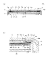
図6(a)は、図1のVI−VI線矢視方向における断面図であり、図6(b)は、図6(a)の領域Aの拡大図である。 6A is a cross-sectional view in the direction of arrows VI-VI in FIG. 1, and FIG. 6B is an enlarged view of region A in FIG.
上述のように、携帯電話機1では、基板26上に、順に、シールドケース27、FPC28(図6(b))、シート部材35、インナーフレーム36、光拡散シート37(図6では図示を省略)、正面側ケース8が積層されている。また、シート部材35の突出部41はインナーフレーム36を貫通し、突出部41上に設けられたダイヤルキー53は正面側ケース8の開口部8aから露出している。
As described above, in the
キーシート24(シート部材35、インナーフレーム36、光拡散シート37)は、携帯電話機1の筐体に組み込まれる前は平面状である。そして、キーシート24は、携帯電話機1の筐体に組み込まれると、線L1で示すように、中央側が縁部側に対して基板26側へ撓んだ(弾性変形した)状態で保持される。換言すれば、キーシート24の断面は、ダイヤルキー53の設けられる部分の特に周縁部分が、開口部8aの縁部に係止される部分よりも筐体内側方向に湾曲した状態となっている。
The key sheet 24 (the
なお、線L1は、キーシート24が撓んでいる状態を概念的に示すものであり、キーシート24の撓みをやや誇張して示している。逆に、キーシート24は、線L1との比較のために、撓んでいない状態で示している。
The line L1 conceptually shows the state where the
キーシート24を撓ませる曲げモーメントM1は、正面側ケース8の開口部8aの縁部に設けられた第1突起8bと、第1突起8bよりも開口部8aの外周側(第1突起8bの設けられる部分に対してキートップとは反対側)において、シールドケース27の天面に設けられた第2突起27bとによってキーシート24に付与されている。換言すれば、曲げモーメントM1は、開口部8aの外周側において付与されている。
The bending moment M1 that bends the
第1突起8bは、例えば樹脂により形成され、正面側ケース8の射出成形時に他の部分と一体的に形成される。第1突起8bは、キーシート24側(筐体内部側)へ突出している。第1突起8bは、例えば、開口部8aの縁部に沿って延びる突条に形成されており、開口部8aの全周に亘って設けられている。第1突起8bの断面形状は適宜に設定してよいが、例えば、略直角三角形に形成されている。三角形の図6(b)の紙面左側の一辺は、開口部8aを形成しており、ダイヤルキー53の押圧方向(紙面上下方向)に平行である。三角形の図6(b)の紙面右側の一辺は、ダイヤルキー53の押圧方向に傾斜しており、第1突起8bの裾野を形成している。三角形の頂部は曲線状に面取りされている。
The
第2突起27bは、例えば、金属により形成され、シールドケース27の他の部分と一体的に設けられている。例えば、板金を、シールドケース27の天面と、天面の周囲の側面とに折り曲げ加工する際に、折り目が天面側に突出するように加工することにより形成される。第2突起27bは、キーシート24側に突出し、FPC28の厚さよりも高く、キーシート24に当接する。第2突起27bは、例えばシールドケース27の天面の縁部に沿って延びる突条に形成されており、シールドケース27の全周に亘って設けられている。この第2突起27bは一例としてシールドケース27に設けているが、FPC28上に設けてもよく、要は、開口部にキートップ、その開口周縁部に第1突起8b、さらに外周部に第2突起27bが配され、かつ、第1突起8bがキーシート24の表側(キートップの設けられる側)を、第2突起27bが裏側を押さえつけることができる位置であればよい。
The
正面側ケース8を背面側ケース9に対して合体させると、第1突起8bは、光拡散シート37(図6では不図示)に当接してキーシート24に筐体内側方向への力F1を加える。キーシート24は、シート部材35に当接している第2突起27bから、反力として、筐体外側方向への力F2を受ける。第2突起27bは、第1突起8bから外周側にずれた位置に配置されているから、キーシート24は、FPC28側へ凸に曲げる方向の曲げモーメントM1を縁部側において付与されることになる。
When the
曲げモーメントM1は、キーシート24の中央側へ伝達され、キーシート24の中央側を筐体内側方向へ付勢する力として働く。換言すれば、キーシート24は、携帯電話機1の筐体に取り付けられた際に、キートップ(ダイヤルキー53等)が筐体内側方向に付勢されるよう開口部8aの縁部にて係止される。従って、キーシート24がFPC28に押さえつけられる形となり、中央側のダイヤルキー53の浮き上がりが防止される。
The bending moment M1 is transmitted to the center side of the
キーシート24は、自重及び曲げモーメントM1により、中央側が撓み、FPC28に当接している。FPC28はシールドケース27の平面状の天面に支持されている。従って、キーシート24は、中央側においてはFPC28を介してシールドケース27に支持されて平面状であり、その外周側において湾曲している。このため、全体としては湾曲しつつも、ダイヤルキー53の配置位置においては平面状であり、ダイヤルキー53は平面的に配置されている。なお、第1突起8b及び第2突起27bは開口部8aの全周に亘って設けられているから、キーシート24は、すり鉢状(球面状)に湾曲し、かつ、FPC28に当接するキートップの設けられる領域はFPC28あるいはシールドケース27天面にて湾曲が補正されて平面となる。
The
図6では、キートップ(各種キー51〜54)の代表として、ダイヤルキー53を図示して説明したが、他のキートップについても、キーシート24に曲げモーメントM1が付与されることにより、浮き上がりが防止されることは同様である。
In FIG. 6, the
シート部材35の縁部には、天面側に突出する突条部35cが設けられている。前面側ケース8の筐体内側には、キーシート24側に突出し、突条部8cの内周側に係合可能な突条部8cが設けられている。突条部35c及び突条部8cは、図6(b)では係合していないが、キーシート24が線L1で示すように湾曲した場合に係合し、キーシート24の弛み及びキーシート24の浮き上がりを防止する。これにより、第2突起27bを支点として突条部8cによる紙面下方向の力が、第2突起27bを挟んで反対側において上方向の力となり、さらにこの上方向の力が、第1突起8bを支点として反対側のキートップの設けられる領域において下方向の力となり、キーシート24をFPC28側に押さえつける力が増すことになる。
At the edge of the
以上の第1の実施形態によれば、キーシート24は、送話筐体3に取り付けられた際に、各種キー51〜54が筐体内側方向に付勢されるよう開口部8aの縁部にて係止されるから、各種キー51〜54を付勢する力によりキーシート24及び各種キー51〜54の浮きが防止される。また、付勢力は縁部の係止によって生じるから、浮き上がり防止のために各種キー51〜54間に筐体と連続して形成されるフレームを介在させて各種キー51〜54を筐体に係合させる必要がない。従って、いわゆる狭ピッチキーにおいても浮き上がりを防止できる。浮き上がりの防止によって、キートップのストロークのばらつきによる操作時のフィーリング不良の抑制や、閉状態におけるキートップと表示部11との接触の抑制等の効果が得られる。
According to the above first embodiment, when the
キーシート24は、その断面において、各種キー51〜54の設けられる部分の特に周縁部が、開口部8aの縁部に係止される部分よりも筐体内側方向に湾曲している。具体的には、送話筐体3に組み込まれていないときに平面状のキーシート24が、送話筐体3に組み込まれることにより曲げモーメントM1が付与されて湾曲している。従って、曲げモーメントM1が各種キー51〜54を付勢する力として働き、キートップの浮き上がりが防止される。さらに、従来のように、平面状のキーシート24の利用が可能である。
In the cross section of the
開口部8aの縁部には、第1突起8bが設けられ、送話筐体3内にキーシート24が取り付けられた際に、第1突起8bによりキーシート24が筐体内部方向に付勢される。従って、送話筐体3の組み立てと同時にキーシート24を付勢することになり、組立工程が簡略化される。
A
第1突起8bよりも開口部8a外周側の位置に、キーシート24を筐体外側方向に付勢する第2突起27bが、FPC28側からキーシート24側へ突出して設けられていることから、キーシート24をFPC28(シールドケース27)に載置することにより、第2突起27bからの付勢力を得て、第1突起8b及び第2突起27bによる曲げモーメントM1を得ることができ、構成が簡単である。
Since the
キーシート24は、キートップが設けられるシート部材35と、シート部材35よりも弾性係数が高く、シート部材35に積層的に配置され、シート部材35を介してキートップを筐体内側方向に付勢するインナーフレーム36とを含んで構成されている。すなわち、インナーフレーム36により剛性が確保されるから、小さな撓みで比較的大きな曲げモーメントM1がキーシート24の中央側に伝達され、浮き上がりが確実に防止されるとともに、キートップの天面を平面状に揃えることが容易となる。また、インナーフレーム36も第1、第2突起がないときに比して強度が小さく済むので、厚さを抑えることができる。
The
また、インナーフレーム36は、シート部材35のキートップが設けられる側の面に配置されているから、インナーフレーム36とシート部材35とを接着しなくても、シート部材35の浮き上がりをインナーフレーム36により抑止できる。
Further, since the
各種キー51〜54は、それぞれ開口部8aからの露出面が突出部38〜42の天面よりも大きく、開口部8aから露出する際に、各種キー51〜54間に何も介在させないように構成されるから、操作部17を小型化しつつ、各種キー51〜54の表面積を大きくして操作性を向上できる。その一方で突出部38〜42間には、弾性変形した突出部38〜42が収納されるスペースを確保できる。
In the
(第2の実施形態)
図7は、第2の実施形態の携帯電話機101を示す断面図である。なお、第1の実施形態と同一の構成については、第1の実施形態と同一符号を付す。
(Second Embodiment)
FIG. 7 is a cross-sectional view showing a
第2の実施形態のキーシート124は、送話筐体3に組み込まれていないとき、線L2で示すように、FPC28側を凸とする曲面状(球面状)である。そして、キーシート24は、送話筐体3に組み込まれたときには、開口部8aの外周側において正面側ケース8の第1突起8bからFPC28への力F3を受けるとともに、開口部8aの内周側においてFPC28を介してシールドケース127からの反力としての力F4を受ける。なお、シールドケース127には、第1の実施形態の第2突起27bに対応する突起は設けられていない。従って、キーシート124は、力F3及びF4により生じた、FPC28側に凹に曲げる曲げモーメントM2を受けて弾性変形し、略平面状になった状態で送話筐体3に組み込まれる。ただし、第2突起27bを設けることもできる。
When the
キーシート124は、曲げモーメントM2に対する反力として、FPC28側を凸とする曲げモーメントを生じている。つまり、弾性変形により、第1突起8bに支持された縁部側に対して、中央側をFPC28側に付勢する復元力F4′(=−F4)を生じている。換言すれば、キーシート124は、送話筐体3に取り付けられた際に、キートップが筐体内側方向に付勢されるよう開口部8aの縁部にて係止される。従って、付勢力によりキートップの浮き上がりが防止される。
The
このような筐体に組み込まれていない(外力を付与されていない)とき湾曲しているキーシート124は、種々の方法により形成可能である。
The
例えば、2色成形特有の2材質間の収縮率を利用する方法がある。例えば、硬化時の収縮率の異なる2種類の熱可塑性樹脂を積層するように射出成形を行ってインナーフレーム136を形成することにより、湾曲したキーシート124を形成することができる。
For example, there is a method of using a shrinkage rate between two materials peculiar to two-color molding. For example, the curved
また、例えば、熱可塑性樹脂によりインナーフレーム136を平面状に射出成形しておき、その後に加熱しつつ曲げモーメントを付与することにより変形させるなど、いわゆるアニールによって形成することもできる。
Further, for example, the
以上の第2の実施形態によれば、第1の実施形態と同様の効果が得られる。すなわち、キーシート124は、送話筐体3に取り付けられた際に、各種キー51〜54が筐体内側方向に付勢されるよう開口部8aの縁部にて係止されるから、各種キー51〜54を付勢する力によりキーシート124及び各種キー51〜54の浮きが防止される。また、付勢力は縁部の係止によって生じるから、浮き上がり防止のために各種キー51〜54間に筐体を介在させて各種キー51〜54を筐体に係合させる必要がない。従って、いわゆる狭ピッチキーにおいても浮き上がりを防止できる。
According to the second embodiment described above, the same effect as in the first embodiment can be obtained. That is, the
キーシート124は、その断面において、各種キー51〜54の設けられる部分が、開口部8aの縁部に係止される部分よりも筐体内側方向に湾曲している。具体的には、キーシート124は、送話筐体3への組み込み前に湾曲している。従って、キーシート124は、送話筐体3に組み込まれて平面状になった状態で復元力F4′を生じ、キートップの浮き上がりが防止され、また、キートップを平面状に配列することが容易になる。
In the cross section of the
開口部8aの縁部には、第1突起8bが設けられ、送話筐体3内にキーシート124が取り付けられた際に、第1突起8bによりキーシート124が筐体内部方向に付勢される。従って、送話筐体3の組み立てと同時にキーシート124の復元力を生じさせることができ、組立工程が簡略化される。
A
キーシート124は、キートップが設けられるシート部材135と、シート部材135よりも弾性係数が高く、シート部材135に積層的に配置され、シート部材135を介してキートップを筐体内側方向に付勢するインナーフレーム136とを含んで構成されている。すなわち、インナーフレーム136により剛性が確保されるから、小さな弾性変形で比較的大きな曲げモーメントM2がキーシート124に生じる。従って、浮き上がりが確実に防止される。
The
本発明は、以上の実施形態に限定されず、種々の態様で実施してよい。 The present invention is not limited to the above embodiment, and may be implemented in various aspects.
本発明が適用される電子機器は、キートップを有するものであればよく、携帯電話機に限定されない。本発明は、ノートパソコンやPDA等の携帯電子機器の他、産業用機械の操作パネルや自動車の操作パネル等、種々の電子機器に利用できる。 The electronic device to which the present invention is applied is not limited to a mobile phone as long as it has a key top. The present invention can be used in various electronic devices such as an operation panel for industrial machines and an operation panel for automobiles, in addition to portable electronic devices such as notebook computers and PDAs.
キーシートの湾曲は、キーシートの少なくとも一部が、所定の方向において湾曲していればよい。従って、中央が縁部全周に対して突出するような球面状の湾曲に限定されず、直線状の尾根を形成するように湾曲していてもよいし、実施形態のように、中央側が基板に当接するなどして平面状になっていてもよい。 The key sheet may be curved as long as at least a part of the key sheet is curved in a predetermined direction. Accordingly, the present invention is not limited to a spherical curve whose center protrudes with respect to the entire circumference of the edge, and may be curved so as to form a straight ridge, and the center side is a substrate as in the embodiment. It may be a flat surface by abutting on the surface.
キーシートへの曲げモーメントの付与は、適宜な方法で行ってよく、第1突起、第2突起によるものに限定されない。例えば、第1突起に代えて、キーシートに挿通され、キー基板に螺合されるねじにより、キーシートをキー基板側へ付勢する力を生じさせてもよい。 The application of the bending moment to the key sheet may be performed by an appropriate method, and is not limited to the one using the first protrusion and the second protrusion. For example, instead of the first protrusion, a force that urges the key sheet toward the key board may be generated by a screw that is inserted into the key sheet and screwed into the key board.
第1突起、第2突起は、キートップを露出させる開口部の全周に亘って設けられていなくてもよい。例えば、開口部が楕円や長方形である場合、長手方向においてキーシートの撓み(浮き上がり)が生じやすいから、開口部の長手方向において対向する縁部側においてのみ第1突起や第2突起を設けるようにしてもよい。また、第1突起、第2突起は、突条部でなくてもよく、例えば、複数の凸部を開口部の周囲に配列するようにしてもよい。 The 1st protrusion and the 2nd protrusion do not need to be provided over the perimeter of the opening part which exposes a keytop. For example, when the opening is an ellipse or a rectangle, the key sheet is likely to be bent (lifted) in the longitudinal direction. Therefore, the first protrusion and the second protrusion are provided only on the opposite edge side in the longitudinal direction of the opening. It may be. In addition, the first protrusion and the second protrusion may not be protrusions, and for example, a plurality of protrusions may be arranged around the opening.
第2突起は、第1突起よりも外周側においてキーシートをキー基板に対して離間させて支持することができればよく、シールドケースに設けられるものに限定されない。例えば、キーシートに設けられ、キー基板側に突出するものでもよい。また、キーシートが載置されるFPCや樹脂基板等の基板に設けられ、キーシート側へ突出するものでもよい。 The second protrusion is not limited to the one provided on the shield case as long as the key sheet can be supported on the outer peripheral side of the first protrusion while being separated from the key substrate. For example, it may be provided on the key sheet and protrude to the key board side. Further, it may be provided on a substrate such as an FPC or a resin substrate on which the key sheet is placed and protrude toward the key sheet side.
第1突起、第2突起は、筐体やシールドケースに一体成形されるものに限定されない。例えば、線状のゴムを開口部の縁部やシールドケース天面の縁部に接着剤等により固定して第1突起、第2突起を設けるなど、後付であってもよい。 The first protrusion and the second protrusion are not limited to those integrally formed with the housing or the shield case. For example, it may be retrofitted such that linear rubber is fixed to the edge of the opening or the edge of the top surface of the shield case with an adhesive or the like to provide the first protrusion and the second protrusion.
インナーフレームは、必須の要件ではなく、また、シート部材のキー基板側に設けられていてもよい。図8に示すように、突出部38〜42に対応する位置に開口部236を有するインナーフレーム236を、シート部材35の筐体内部側に接合してキーシートを構成してもよい。この場合、突出部38〜42のストロークを確保しやすい。
The inner frame is not an essential requirement, and may be provided on the key board side of the sheet member. As shown in FIG. 8, a key sheet may be configured by joining an
第1実施形態と第2実施形態とを組み合わせてもよい。例えば、筐体に組み込まれる前において、中央側ほどキートップ側を凹として湾曲し(中央側ほど曲率が高く、又は、外周側は平板状)、中央側から第1突起8bまでは第1の実施形態の線L1よりも湾曲するキーシートを、第1の実施形態の第1突起8b及び第2突起27bにより挟み込む。この場合、第1突起8bの下方への力と、キーシート中央側におけるFPC28からの反力とにより、中央側の湾曲が線L1の位置まで矯正されて、第2の実施形態のように、キーシートのキートップが設けられる領域をFPC28に押し付ける復元力が生じる。そして、第1突起8bにより湾曲が矯正された状態では第1突起8bよりも外周側は線L1よりも下方に位置しようとするが、第2突起27bにより上方の力が付与され、当該上方への力は、第1の実施形態のように、第1突起8bを支点としてキーシートのキートップが設けられる領域をFPC28に押し付ける力になり(曲げモーメントM1が付与され)、キーシートをFPC28に押し付ける力が増加する。従って、より確実にキートップの浮き上がりを防止可能である。
The first embodiment and the second embodiment may be combined. For example, before being assembled into the housing, the center side is curved with the key top side being concave (the center side is higher in curvature, or the outer peripheral side is flat), and the
1…携帯電話機(携帯電子機器)、3…送話筐体、8a…開口部、24…キーシート、26…キー基板、31…押圧スイッチ。
DESCRIPTION OF
Claims (16)
前記筐体内部に設けられ、複数の押圧スイッチを有するキー基板と、
前記複数の押圧スイッチに被せられ、前記筐体内部に設けられるキーシートと、
前記キーシート上に前記複数の押圧スイッチに対応して設けられ、前記開口部から露出する複数のキートップと、
を備え、
前記キーシートは、前記筐体に取り付けられた際に、前記キートップを有する部位が筐体内側方向に付勢されるように構成してあることを特徴とする
携帯電子機器。 A housing having an opening;
A key board provided in the housing and having a plurality of press switches;
A key sheet that is put on the plurality of push switches and provided inside the housing;
A plurality of key tops provided on the key sheet corresponding to the plurality of press switches, and exposed from the opening;
With
The portable electronic device according to claim 1, wherein the key sheet is configured such that when the key sheet is attached to the housing, the portion having the key top is biased toward the inside of the housing.
前記キーシートは、
前記キートップが設けられるシート部材と、
前記シート部材よりも弾性係数が高く、前記シート部材に積層的に配置されるインナーフレームと、
を含んで構成されている携帯電子機器。 In any one of Claims 1-4,
The key sheet is
A sheet member provided with the key top;
An inner frame that has a higher elastic coefficient than the sheet member and is disposed in a stacked manner on the sheet member;
A portable electronic device configured to include.
前記インナーフレームは、前記突出部を貫通させる孔部が複数形成されている携帯電子機器。 In claim 6, the sheet member is formed with a plurality of protrusions on which the key tops are placed,
The inner frame is a portable electronic device in which a plurality of holes that allow the protrusions to pass therethrough are formed.
前記筐体内部に設けられ、複数の押圧スイッチを有するキー基板と、
前記複数の押圧スイッチに被せられ、前記筐体内部に設けられるキーシートと、
前記キーシート上において前記複数の押圧スイッチに対応して設けられ、前記開口部から露出する複数のキートップと、
を備え、
前記キーシートは、前記キー基板側へ凸に曲げる方向の曲げモーメントを、前記開口部の外周側から付与された状態で保持されている
携帯電子機器。 A housing having an opening;
A key board provided in the housing and having a plurality of press switches;
A key sheet that is put on the plurality of push switches and provided inside the housing;
A plurality of key tops provided on the key sheet corresponding to the plurality of push switches and exposed from the opening;
With
The portable electronic device, wherein the key sheet is held in a state in which a bending moment in a direction in which the key sheet is convexly bent toward the key substrate is applied from the outer peripheral side of the opening.
前記筐体内部に設けられ、複数の押圧スイッチを有するキー基板と、
前記複数の押圧スイッチに被せられるように前記キー基板上に配され、前記筐体内部に設けられるキーシートと、
前記キーシート上において前記複数の押圧スイッチに対応して設けられ、前記開口部から露出する複数のキートップと、
を備え、
前記キーシートは、前記開口部の内周側において前記キー基板から受ける前記キートップ側への力と、前記開口部の外周側において受ける前記キー基板側への力とにより、弾性変形した状態で保持されている
携帯電子機器。 A housing having an opening;
A key board provided in the housing and having a plurality of press switches;
A key sheet disposed on the key substrate so as to be covered with the plurality of push switches, and provided inside the housing;
A plurality of key tops provided on the key sheet corresponding to the plurality of push switches and exposed from the opening;
With
The key sheet is elastically deformed by a force toward the key top received from the key substrate on the inner peripheral side of the opening and a force toward the key substrate received on the outer peripheral side of the opening. Held portable electronic device.
前記複数のキートップが設けられる側の面が前記複数のキートップの設けられる部分の周囲に比べて凹となるように形成され、
前記複数のキートップは、互いに連続して設けられ、前記開口部にて露出する際に、隣り合うキートップ間には何も介在させないよう構成されている
キーシート。 A key sheet having a plurality of key tops exposed from an opening formed in a housing,
The surface on the side where the plurality of key tops are provided is formed to be concave compared to the periphery of the portion where the plurality of key tops are provided,
The key sheet is configured such that the plurality of key tops are provided continuously with each other, and nothing is interposed between adjacent key tops when exposed at the opening.
前記キートップが設けられるシート部材と、
前記シート部材よりも弾性係数が高く、前記シート部材に積層的に配置されるインナーフレームと、
を含んで構成されているキーシート。 In claim 12,
A sheet member provided with the key top;
An inner frame that has a higher elastic coefficient than the sheet member and is disposed in a stacked manner on the sheet member;
A key sheet composed of
前記インナーフレームは、前記突出部を貫通させる孔部が複数形成されているキーシート。 In Claim 14, a plurality of protrusions on which the key tops are placed are formed on the sheet member,
The inner frame is a key sheet in which a plurality of holes that allow the protrusions to pass therethrough are formed.
Priority Applications (1)
| Application Number | Priority Date | Filing Date | Title |
|---|---|---|---|
| JP2005336026A JP4743701B2 (en) | 2005-11-21 | 2005-11-21 | Portable electronic devices |
Applications Claiming Priority (1)
| Application Number | Priority Date | Filing Date | Title |
|---|---|---|---|
| JP2005336026A JP4743701B2 (en) | 2005-11-21 | 2005-11-21 | Portable electronic devices |
Publications (2)
| Publication Number | Publication Date |
|---|---|
| JP2007141076A true JP2007141076A (en) | 2007-06-07 |
| JP4743701B2 JP4743701B2 (en) | 2011-08-10 |
Family
ID=38203837
Family Applications (1)
| Application Number | Title | Priority Date | Filing Date |
|---|---|---|---|
| JP2005336026A Expired - Fee Related JP4743701B2 (en) | 2005-11-21 | 2005-11-21 | Portable electronic devices |
Country Status (1)
| Country | Link |
|---|---|
| JP (1) | JP4743701B2 (en) |
Cited By (7)
| Publication number | Priority date | Publication date | Assignee | Title |
|---|---|---|---|---|
| JP2010067194A (en) * | 2008-09-12 | 2010-03-25 | Fujitsu Ltd | Electronic apparatus |
| JP2010086279A (en) * | 2008-09-30 | 2010-04-15 | Fujitsu Ltd | Keyboard adapter, keyboard mounting system and electronic apparatus |
| US7813269B2 (en) | 2008-05-13 | 2010-10-12 | Kabushiki Kaisha Toshiba | Communication apparatus and abnormality restoration method |
| US7891828B2 (en) | 2008-05-26 | 2011-02-22 | Kabushiki Kaisha Toshiba | Electronic device |
| KR101263123B1 (en) | 2010-11-09 | 2013-05-15 | 후지쯔 가부시끼가이샤 | Electronic device |
| JP2013098652A (en) * | 2011-10-28 | 2013-05-20 | Panasonic Corp | Portable terminal |
| JP2017156961A (en) * | 2016-03-01 | 2017-09-07 | レノボ・シンガポール・プライベート・リミテッド | Keyboard unit attachment structure |
Citations (6)
| Publication number | Priority date | Publication date | Assignee | Title |
|---|---|---|---|---|
| JPH0763584A (en) * | 1993-08-25 | 1995-03-10 | Yazaki Corp | Sound-proof structure of measuring instrument |
| JPH10149109A (en) * | 1996-11-20 | 1998-06-02 | Fujitsu General Ltd | Plane display device |
| JP2003066852A (en) * | 2001-08-24 | 2003-03-05 | Sanyo Electric Co Ltd | Plasma display device |
| JP2004227855A (en) * | 2003-01-21 | 2004-08-12 | Alps Electric Co Ltd | Illumination mechanism of rotating operation type electrical component |
| JP2004327420A (en) * | 2003-04-11 | 2004-11-18 | Polymatech Co Ltd | Key sheet and method of manufacturing key sheet |
| JP2005123742A (en) * | 2003-10-14 | 2005-05-12 | Sanyo Electric Co Ltd | Communication apparatus |
-
2005
- 2005-11-21 JP JP2005336026A patent/JP4743701B2/en not_active Expired - Fee Related
Patent Citations (6)
| Publication number | Priority date | Publication date | Assignee | Title |
|---|---|---|---|---|
| JPH0763584A (en) * | 1993-08-25 | 1995-03-10 | Yazaki Corp | Sound-proof structure of measuring instrument |
| JPH10149109A (en) * | 1996-11-20 | 1998-06-02 | Fujitsu General Ltd | Plane display device |
| JP2003066852A (en) * | 2001-08-24 | 2003-03-05 | Sanyo Electric Co Ltd | Plasma display device |
| JP2004227855A (en) * | 2003-01-21 | 2004-08-12 | Alps Electric Co Ltd | Illumination mechanism of rotating operation type electrical component |
| JP2004327420A (en) * | 2003-04-11 | 2004-11-18 | Polymatech Co Ltd | Key sheet and method of manufacturing key sheet |
| JP2005123742A (en) * | 2003-10-14 | 2005-05-12 | Sanyo Electric Co Ltd | Communication apparatus |
Cited By (7)
| Publication number | Priority date | Publication date | Assignee | Title |
|---|---|---|---|---|
| US7813269B2 (en) | 2008-05-13 | 2010-10-12 | Kabushiki Kaisha Toshiba | Communication apparatus and abnormality restoration method |
| US7891828B2 (en) | 2008-05-26 | 2011-02-22 | Kabushiki Kaisha Toshiba | Electronic device |
| JP2010067194A (en) * | 2008-09-12 | 2010-03-25 | Fujitsu Ltd | Electronic apparatus |
| JP2010086279A (en) * | 2008-09-30 | 2010-04-15 | Fujitsu Ltd | Keyboard adapter, keyboard mounting system and electronic apparatus |
| KR101263123B1 (en) | 2010-11-09 | 2013-05-15 | 후지쯔 가부시끼가이샤 | Electronic device |
| JP2013098652A (en) * | 2011-10-28 | 2013-05-20 | Panasonic Corp | Portable terminal |
| JP2017156961A (en) * | 2016-03-01 | 2017-09-07 | レノボ・シンガポール・プライベート・リミテッド | Keyboard unit attachment structure |
Also Published As
| Publication number | Publication date |
|---|---|
| JP4743701B2 (en) | 2011-08-10 |
Similar Documents
| Publication | Publication Date | Title |
|---|---|---|
| JP4743701B2 (en) | Portable electronic devices | |
| KR101050030B1 (en) | Electronics | |
| US20160365887A1 (en) | Case for a hand held device | |
| US11501932B2 (en) | Illuminated keypad module for an electric lock | |
| US8207462B2 (en) | Key structure having improved light emitting efficiency | |
| US8704113B2 (en) | Keyboard and electronic apparatus | |
| US20100148994A1 (en) | Keyboard with Backlighting Functionality | |
| US20080314722A1 (en) | Movable contact assembly and switch using the same | |
| US20110074608A1 (en) | Button-key device and portable terminal apparatus | |
| US7679015B2 (en) | Keypad assembly for electronic device | |
| JP4908280B2 (en) | Method for manufacturing light guide plate | |
| JP2009075980A (en) | Keyboard, electronic apparatus and method of manufacturing keyboard | |
| JP4371895B2 (en) | Key switch structure | |
| JP2010027568A (en) | Key switch structure | |
| JP4647452B2 (en) | Electronics | |
| JP2019121594A (en) | Key sheet and electronic equipment including the same | |
| JP4699404B2 (en) | Portable electronic devices | |
| JP2010049812A (en) | Key switch structure | |
| US8665220B2 (en) | System for securing a keypad to a housing | |
| JP4749371B2 (en) | Portable electronic devices | |
| JP2011159565A (en) | Dome sheet, printed wiring board, key module and electronic device | |
| JP2008159346A (en) | Portable electronic equipment | |
| JP4273868B2 (en) | Panel switch | |
| JP5340855B2 (en) | Portable electronic device and switch structure | |
| KR20130120998A (en) | Electrical switch, of the normally-closed type, especially for a portable communication device |
Legal Events
| Date | Code | Title | Description |
|---|---|---|---|
| A621 | Written request for application examination |
Free format text: JAPANESE INTERMEDIATE CODE: A621 Effective date: 20080902 |
|
| A977 | Report on retrieval |
Free format text: JAPANESE INTERMEDIATE CODE: A971007 Effective date: 20100830 |
|
| A131 | Notification of reasons for refusal |
Free format text: JAPANESE INTERMEDIATE CODE: A131 Effective date: 20100907 |
|
| A521 | Written amendment |
Free format text: JAPANESE INTERMEDIATE CODE: A523 Effective date: 20101105 |
|
| A01 | Written decision to grant a patent or to grant a registration (utility model) |
Free format text: JAPANESE INTERMEDIATE CODE: A01 Effective date: 20110405 |
|
| A61 | First payment of annual fees (during grant procedure) |
Free format text: JAPANESE INTERMEDIATE CODE: A61 Effective date: 20110502 |
|
| FPAY | Renewal fee payment (event date is renewal date of database) |
Free format text: PAYMENT UNTIL: 20140520 Year of fee payment: 3 |
|
| R150 | Certificate of patent or registration of utility model |
Free format text: JAPANESE INTERMEDIATE CODE: R150 |
|
| LAPS | Cancellation because of no payment of annual fees |