JP2007135268A - Stator of ultrasonic motor - Google Patents
Stator of ultrasonic motor Download PDFInfo
- Publication number
- JP2007135268A JP2007135268A JP2005323736A JP2005323736A JP2007135268A JP 2007135268 A JP2007135268 A JP 2007135268A JP 2005323736 A JP2005323736 A JP 2005323736A JP 2005323736 A JP2005323736 A JP 2005323736A JP 2007135268 A JP2007135268 A JP 2007135268A
- Authority
- JP
- Japan
- Prior art keywords
- stator
- rotor
- ultrasonic motor
- piezoelectric element
- comb teeth
- Prior art date
- Legal status (The legal status is an assumption and is not a legal conclusion. Google has not performed a legal analysis and makes no representation as to the accuracy of the status listed.)
- Withdrawn
Links
Images


Abstract
Description
本発明は超音波モータ等の振動体に用いられるステータに関するものである。 The present invention relates to a stator used for a vibrating body such as an ultrasonic motor.
従来から、磁力を使わずにステータ側の圧電素子の振動により、そのステータに接するロータを駆動することができる超音波モータの開発が進んでいる。 2. Description of the Related Art Conventionally, an ultrasonic motor that can drive a rotor in contact with a stator by vibration of a piezoelectric element on the stator side without using magnetic force has been developed.
超音波モータではステータの数やロータの形状を工夫することによって様々な用途に用いることができ、たとえばディスク型やリング型のロータがすでによく知られている。また最近では、ロータを球体にした球面超音波モータの開発も進んできている。 Ultrasonic motors can be used for various purposes by devising the number of stators and the shape of the rotor. For example, disk-type and ring-type rotors are already well known. Recently, development of a spherical ultrasonic motor having a rotor as a sphere has also been advanced.
このような超音波モータのステータは、たとえば平板円環状の圧電素子の所定個所を所定方向に分極させてA相およびB相を形成して圧電素子部材とし、この圧電素子部材のA相、B相ごとに設けた駆動電極に対して所定電圧を印加して圧電素子部材を固着した弾性体に進行波を発生させる。その進行波形成面にロータを加圧接触させて摩擦によりロータが回転する。 A stator of such an ultrasonic motor is formed by, for example, polarizing a predetermined portion of a flat plate-shaped piezoelectric element in a predetermined direction to form an A phase and a B phase as piezoelectric element members. A traveling wave is generated in the elastic body to which the piezoelectric element member is fixed by applying a predetermined voltage to the drive electrode provided for each phase. The rotor is brought into pressure contact with the traveling wave forming surface, and the rotor is rotated by friction.
特許文献1や特許文献2には、従来の超音波モータのステータの櫛歯の形状が開示されている。この従来のステータの構造について図面を参照して以下に説明する。
図8は、従来の超音波モータのステータを示す図であり、(a)はロータの接触する方向から見た平面図であり、(b)は櫛歯部分の側断面図である。 8A and 8B are views showing a stator of a conventional ultrasonic motor, in which FIG. 8A is a plan view seen from the direction in which the rotor contacts, and FIG. 8B is a side sectional view of a comb tooth portion.
図8(a)に示すように、ステータ203bのロータ接触面には、ステータ203bの円周に沿って多数の櫛歯233が設けられている。このステータの裏面には、リング状の圧電素子部材が固着されており、交流電圧の印加により伸縮を繰り返し、ステータの周方向に進行波が発生する。
As shown in FIG. 8A, a large number of
櫛歯233は、櫛歯の凸部に加圧接触される図示なきロータを効率よく回転させるために、ロータの回転方向の振動振幅を拡大する効果がある。
The
従来の超音波モータのステータ203bでは、図8(a)および(b)に示すように、円板状のステータ203bの円周の法線と一致する方向で放射線状に設けた複数のスリット233aにより櫛歯233を形成している。
In the conventional
従来から超音波モータでは効率をより向上させてトルクを増大させることが課題となっていた。 Conventionally, in an ultrasonic motor, it has been a problem to increase the torque by improving the efficiency.
本発明は上記の点にかんがみてなされたもので、ステータの振動振幅に大きく影響する櫛歯とそれを形成させるスリットの形状を改良して超音波モータの効率向上とトルクを増大することができるステータを提供することを目的とする。 The present invention has been made in view of the above points, and it is possible to improve the efficiency of the ultrasonic motor and increase the torque by improving the shape of the comb teeth that greatly affect the vibration amplitude of the stator and the slits that form the comb teeth. An object is to provide a stator.
本発明は、弾性体に固着した複数の圧電体により進行波を形成するステータと、ロータとを備え、前記ステータの進行波形成面に前記ロータを加圧接触させて回転するように構成した超音波モータのステータにおいて、前記ステータの周方向に複数の櫛歯を備え、円周上の法線と所定の角度を有して設けた複数のスリットにより前記櫛歯を形成していることを特徴とする。 The present invention includes a stator that forms a traveling wave by a plurality of piezoelectric bodies fixed to an elastic body, and a rotor, and is configured to rotate by bringing the rotor into pressure contact with the traveling wave forming surface of the stator and rotating the rotor. In the stator of a sonic motor, a plurality of comb teeth are provided in the circumferential direction of the stator, and the comb teeth are formed by a plurality of slits provided at a predetermined angle with a normal line on the circumference. And
本発明によれば、櫛歯の長さが長くなるため、振幅が増大し、超音波モータのトルクを増大させることができる。 According to the present invention, since the length of the comb teeth is increased, the amplitude is increased and the torque of the ultrasonic motor can be increased.
また本発明によれば、ステータ表面のスリットが円周方向に傾いているため、円周方向の剛性の均一化が図られ、進行波が安定するという効果もある。 Further, according to the present invention, since the slits on the stator surface are inclined in the circumferential direction, the rigidity in the circumferential direction can be made uniform, and the traveling wave can be stabilized.
以下、本発明の実施の形態について図面を参照して詳細に説明する。 Hereinafter, embodiments of the present invention will be described in detail with reference to the drawings.
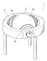
図1は、本発明の一実施の形態による球面超音波モータの概略を示す斜視図である。 FIG. 1 is a perspective view schematically showing a spherical ultrasonic motor according to an embodiment of the present invention.
なお、本実施の形態ではロータが球体である球面超音波モータの場合について説明するが、本発明による超音波モータのステータは、円板状のロータに対しても適用することができる。 In the present embodiment, a case of a spherical ultrasonic motor in which the rotor is a sphere will be described. However, the stator of the ultrasonic motor according to the present invention can also be applied to a disk-shaped rotor.
図1に示すように、本実施の形態による超音波モータ1は、球体のロータ2を、枠部材4に設けられた3個のステータ3a、3bおよび3cによって保持して回転させる。ステータ3a、3bおよび3cのロータ2と接する面には後に図2に示す多数の櫛歯33が設けられており、この櫛歯33が振動して進行波を発生し、これによってロータ2が回転させられる。
As shown in FIG. 1, the
なお、本実施の形態においては各ステータ3a、3b、3cの構造は同様であるので、以下では代表してステータ3bについて説明する。
In the present embodiment, the structures of the
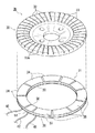
図2は、図1に示したステータ3bを、ロータ2の接触面から見た平面図である。
FIG. 2 is a plan view of the
図2に示すように、ステータ3bのロータ2の接触面には、ステータ3bの円周に沿って多数の櫛歯33が設けられている。これらの櫛歯33の下には後に図3に示す圧電素子部材31が設けられており、その圧電素子部材の圧電素子は電圧印加によって伸縮し櫛歯33を振動させる。超音波モータ1では、この振動を制御することによってロータ2を任意の方向に回転させることができる。
As shown in FIG. 2, a large number of
本実施の形態のステータ3bでは、図2に示すように、円板状のステータ3bの円周の法線と成す角度が10°となる方向で放射線状に、隣接する櫛歯233どうしを分離するスリット33aを設け、これによって複数の櫛歯33のそれぞれを形成している。
In the
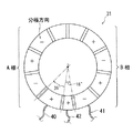
図3は、図2に示したステータ3bを弾性体30と圧電素子部材31とに分解して示す分解斜視図である。
3 is an exploded perspective view showing the
図3に示すように、ステータ3bは弾性体30と圧電素子部材31とから構成される。
As shown in FIG. 3, the
弾性体30の表面には、図2にも示したように、スリット33aで分離された複数の櫛歯33が設けられている。
As shown in FIG. 2, a plurality of
圧電素子部材31は、平板円環状の圧電素子36と、圧電素子36のうちの所定の圧電素子片にA相のための所定方向の分極をさせるための個別電極34と、圧電素子36のうちの所定の圧電素子片にB相のための所定方向の分極をさせるための個別電極35と、A相の圧電素子片を駆動するための駆動電極38と、B相の圧電素子片を駆動するための駆動電極37と、圧電素子36のうちの所定の圧電素子片に振動検出用の所定方向の分極をさせるための個別電極50と、圧電素子36の振動によって個別電極50下の圧電素子片が発生する電位を検出するための振動検出用電極51と、A相の駆動電極38に電圧印加するための配線40と、B相の駆動電極37に電圧印加するための配線41と、振動検出用電極51から電位検出するための配線42とを有して構成される。
The
個別電極34、個別電極35、個別電極50、振動検出用電極51、駆動電極37および駆動電極38はたとえば銀電極であり、配線40、配線41および配線42のそれぞれは、たとえばハンダ付けによって、配線40が駆動電極38に、配線41が駆動電極37に、配線42が振動検出用電極51に接続される。
The
図4は、図3に示したステータ3bの圧電素子部材31の構造を示す図であり、(a)は圧電素子部材31の斜視図であり、(b)は(a)を一点鎖線で示す軸X−Xで回転させて裏から見た斜視図であり、(c)は(a)の一部を破断して示す部分破断斜視図である。
4A and 4B are views showing the structure of the
図4(a)〜(c)に示すように、圧電素子部材31では、平板円環状の圧電素子36の円周方向の一部をA相、円周方向の他の一部をB相とし、A相とB相とを時間的に位相をずらして駆動して、振動の進行波を発生させる。
As shown in FIGS. 4A to 4C, in the
図5は、図4(a)に示した本実施の形態の圧電素子部材31の分極方向を示す平面図である。
FIG. 5 is a plan view showing the polarization direction of the
図4(a)に示すように、本実施の形態の圧電素子部材31は、円周方向左側部分がA相とされ、そのA相にて分極方向が逆の圧電素子片が交互に、それぞれたとえば36°の角度を有して設けられており、また、円周方向右側部分がB相とされ、そのB相にて分極方向が逆の圧電素子片が交互に、それぞれたとえば36°の角度を有して設けられている。また、図5に示すように、A相とB相とはたとえば18°ずらして構成されている。
As shown in FIG. 4A, in the
図6は超音波モータのトルクを測定した実験結果を示す図である。 FIG. 6 is a diagram showing experimental results of measuring the torque of the ultrasonic motor.
図6においては、図8(a)および(b)に示した従来のステータおよび図2に示した本実施の形態のステータのトルクを示し、それぞれにおいてロータをステータに押し付ける押付力を1kgにした場合および1.5kgにした場合でのトルクを示している。 6 shows the torque of the conventional stator shown in FIGS. 8A and 8B and the stator of the present embodiment shown in FIG. 2, and the pressing force for pressing the rotor against the stator is 1 kg in each case. The torque in the case of the case and 1.5 kg is shown.
図6を参照してわかるように、押付力を1kgにした場合および1.5kgにした場合のいずれにおいても、図8(a)および(b)のようにステータ表面のスリット233aとステータ203bの円周の法線とが成す角度が0°の場合(図6では0°と示す)よりも、図2のようにステータ表面のスリット33aとステータ3bの円周の法線とが成す角度が10°の場合(図6では10°と示す)の方が、大きなトルクが得られた。
As can be seen with reference to FIG. 6, in both cases where the pressing force is 1 kg and 1.5 kg, the
ところで、図2に示した実施の形態では、ステータ表面のスリットとステータの円周の法線とが成す角度を10°にしたが、本発明はこれに限られるものではなく、必要に応じた角度にすることができる。この一例を図7に示す。 By the way, in the embodiment shown in FIG. 2, the angle formed by the slit on the stator surface and the normal line of the circumference of the stator is 10 °, but the present invention is not limited to this, and it can be changed according to necessity. Can be an angle. An example of this is shown in FIG.
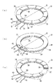
図7は、本発明によるステータの図2とは別の例を示す平面図である。 FIG. 7 is a plan view showing another example of the stator according to the present invention different from FIG.
図7に示すように、この例のステータ103bでは、円板状のステータ103bの円周の法線と成す角度が30°となる方向で放射線状に、隣接する櫛歯133どうしを分離するスリット133aを設け、これによって複数の櫛歯133のそれぞれを形成している。本発明は、この図7のような構成にすることもできる。
As shown in FIG. 7, in the
1 位置検出装置
2 ロータ
3a、3b、3c ステータ
4 枠部材
30 弾性体
31 圧電素子部材
33 櫛歯
33a スリット
34、35 固定電極
36 圧電素子
37、38 駆動電極
40、41 配線
DESCRIPTION OF
Claims (2)
前記ステータの周方向に複数の櫛歯を備え、円周上の法線と所定の角度を有して設けた複数のスリットにより前記櫛歯を形成していることを特徴とする超音波モータのステータ。 A stator for an ultrasonic motor, comprising: a stator that forms a traveling wave with a plurality of piezoelectric bodies fixed to an elastic body; and a rotor, wherein the rotor is rotated in pressure contact with the traveling wave forming surface of the stator. In
An ultrasonic motor comprising a plurality of comb teeth in a circumferential direction of the stator, and the comb teeth are formed by a plurality of slits provided at a predetermined angle with a normal line on the circumference. Stator.
Priority Applications (1)
| Application Number | Priority Date | Filing Date | Title |
|---|---|---|---|
| JP2005323736A JP2007135268A (en) | 2005-11-08 | 2005-11-08 | Stator of ultrasonic motor |
Applications Claiming Priority (1)
| Application Number | Priority Date | Filing Date | Title |
|---|---|---|---|
| JP2005323736A JP2007135268A (en) | 2005-11-08 | 2005-11-08 | Stator of ultrasonic motor |
Publications (1)
| Publication Number | Publication Date |
|---|---|
| JP2007135268A true JP2007135268A (en) | 2007-05-31 |
Family
ID=38156490
Family Applications (1)
| Application Number | Title | Priority Date | Filing Date |
|---|---|---|---|
| JP2005323736A Withdrawn JP2007135268A (en) | 2005-11-08 | 2005-11-08 | Stator of ultrasonic motor |
Country Status (1)
| Country | Link |
|---|---|
| JP (1) | JP2007135268A (en) |
Cited By (2)
| Publication number | Priority date | Publication date | Assignee | Title |
|---|---|---|---|---|
| US8061047B2 (en) | 2009-04-08 | 2011-11-22 | Schlumberger Technology Corporation | Active positioning of downhole devices using spherical motors |
| JP2018188275A (en) * | 2017-05-09 | 2018-11-29 | シンフォニアテクノロジー株式会社 | Workpiece conveying device |
-
2005
- 2005-11-08 JP JP2005323736A patent/JP2007135268A/en not_active Withdrawn
Cited By (2)
| Publication number | Priority date | Publication date | Assignee | Title |
|---|---|---|---|---|
| US8061047B2 (en) | 2009-04-08 | 2011-11-22 | Schlumberger Technology Corporation | Active positioning of downhole devices using spherical motors |
| JP2018188275A (en) * | 2017-05-09 | 2018-11-29 | シンフォニアテクノロジー株式会社 | Workpiece conveying device |
Similar Documents
| Publication | Publication Date | Title |
|---|---|---|
| JP5110170B2 (en) | Piezoelectric vibrator and ultrasonic motor | |
| US20110025167A1 (en) | Ultrasonic Motor | |
| JPH0117354B2 (en) | ||
| KR101040474B1 (en) | Piezo actuator having electrode structure for the torsional vibration mode and ultrasonic motor containing the same | |
| JP4119903B2 (en) | Flat plate piezoelectric ultrasonic motor | |
| JPH07115782A (en) | Vibration wave driver | |
| JP2007135268A (en) | Stator of ultrasonic motor | |
| JP4261894B2 (en) | Vibration type driving device | |
| JP2981471B2 (en) | Double-sided drive ultrasonic motor | |
| JP2007221845A (en) | Spherical ultrasonic motor | |
| JP2007135267A (en) | Ultrasonic motor | |
| JP2013201813A (en) | Driving device and motor | |
| JP2532425B2 (en) | Ultrasonic motor | |
| JP7392874B2 (en) | ultrasonic motor | |
| JP4497980B2 (en) | Piezoelectric body and polarization method thereof | |
| JPH0681523B2 (en) | Vibration wave motor | |
| JPS62247770A (en) | Ultrasonic motor | |
| JPS63181676A (en) | Ultrasonic rotary vibrator | |
| JP4731737B2 (en) | Vibration wave motor | |
| JPS60183981A (en) | Supersonic wave motor | |
| JP2003143877A (en) | Motor with piezoelectric element | |
| JP3089324B2 (en) | Ultrasonic motor | |
| JP2001298969A (en) | Ultrasonic motor | |
| JPS6344970A (en) | Ultrasonic vibrator and drive control method thereof | |
| JP2537848B2 (en) | Ultrasonic motor |
Legal Events
| Date | Code | Title | Description |
|---|---|---|---|
| A300 | Withdrawal of application because of no request for examination |
Free format text: JAPANESE INTERMEDIATE CODE: A300 Effective date: 20090203 |