JP2007128582A - Clamp device and disk device equipped therewith - Google Patents
Clamp device and disk device equipped therewith Download PDFInfo
- Publication number
- JP2007128582A JP2007128582A JP2005319012A JP2005319012A JP2007128582A JP 2007128582 A JP2007128582 A JP 2007128582A JP 2005319012 A JP2005319012 A JP 2005319012A JP 2005319012 A JP2005319012 A JP 2005319012A JP 2007128582 A JP2007128582 A JP 2007128582A
- Authority
- JP
- Japan
- Prior art keywords
- clamper
- disc
- disk
- holder
- receiving portion
- Prior art date
- Legal status (The legal status is an assumption and is not a legal conclusion. Google has not performed a legal analysis and makes no representation as to the accuracy of the status listed.)
- Pending
Links
Images


Abstract
Description
本発明は、例えば、映像用や音楽用あるいはコンピュータ・データ用等の情報記録媒体としてのディスクを、当該ディスクの記録再生時などにクランプするクランプ装置、及びかかるクランプ装置を備えたディスク装置に関する。 The present invention relates to a clamp device that clamps a disc as an information recording medium for video, music, computer data, etc., for example, at the time of recording / reproducing the disc, and a disc device provided with such a clamp device.
近年、情報の記録再生分野におけるディジタル化の進展は著しく、情報記録媒体としてのディスクについても、従来の音声のみをディジタル録音する用途から動画像と音声とをディジタル録画する用途へと、その用途の拡大が急速に進展しつつある。このため、ディスクの記録容量のより一層の増大と、より高速での安定した記録及び/又は再生を可能とする記録再生技術の確立とが求められている。尚、本明細書において、「(ディスクについて)記録及び/又は再生」とは、「(ディスクへの情報の)記録および(ディスクに記録された情報の)再生の少なくとも何れか一方」を簡略化して表現したものである。 In recent years, digitalization in the field of information recording / reproduction has progressed remarkably, and with regard to discs as information recording media, the conventional use of digital recording of only audio is changed to the use of digital recording of moving images and audio. Expansion is progressing rapidly. Therefore, there is a demand for further increase in the recording capacity of the disc and establishment of a recording / reproducing technique that enables stable recording and / or reproduction at a higher speed. In this specification, “recording and / or reproducing (with respect to a disc)” means “at least one of recording (information on the disc) and reproduction (information recorded on the disc)”. It is what was expressed.
上記のような要請の高まりの中で、情報信号をディジタルで記録再生できる大容量のディスク型情報記録媒体として、所謂、記録型DVD(ディジタル・バーサタイル・ディスク)が脚光を浴びている。
この記録型DVDとしては、ライトワンス記録(一回記録)タイプの所謂DVD−Rディスクと、書換型の所謂DVD−RAMディスク,DVD−RWディスクとが、広く知られており、この中でも特にDVD−RAMディスクは、大容量の情報記録媒体として、映像の録画あるいはコンピュータ・データの蓄積などの分野において普及が進んでいる。
Under the growing demand as described above, a so-called recordable DVD (digital versatile disk) is in the spotlight as a large capacity disk type information recording medium capable of digitally recording and reproducing information signals.
As this recordable DVD, a so-called DVD-R disk of a write-once recording (single recording) type and a so-called rewritable so-called DVD-RAM disk and DVD-RW disk are widely known. -RAM disks are widely used as large-capacity information recording media in fields such as video recording and computer data storage.
これら記録型DVDは、光学的に情報の記録再生を行うものであるので、ゴミや汚れの影響を受け易く、その表面にゴミや指紋等が付着していると、安定した記録再生が不能となる場合がある。そこで、何れの記録型DVDについても、DVD収納用のカートリッジが規格で定められており、特にDVD−RAMディスクの場合、このようなカートリッジ(以下、適宜、RAMカートリッジと称する)に収納した状態で使用するタイプのものもある。 Since these recordable DVDs optically record and reproduce information, they are easily affected by dust and dirt. If dust or fingerprints adhere to the surface, stable recording and reproduction cannot be performed. There is a case. Therefore, for any recordable DVD, a cartridge for storing a DVD is defined by the standard. In particular, in the case of a DVD-RAM disc, it is stored in such a cartridge (hereinafter referred to as a RAM cartridge as appropriate). Some types are used.
また、近年では、高画質放送の開始に伴い、その映像を高画質で録画するためにより大容量の情報記録媒体が求められている。このため、従来の記録型DVDを記録再生する際に適用される赤色レーザ光よりも波長が短い青色レーザ光を適用することによって記録密度を飛躍的に向上させた、所謂、ブルーレイディスクと称される(以下、適宜、BDと略称する)情報記録媒体の商品化が進められている。 In recent years, with the start of high-quality broadcasting, a larger capacity information recording medium is required to record the video with high quality. For this reason, it is called a so-called Blu-ray disc, in which the recording density is drastically improved by applying blue laser light having a shorter wavelength than the red laser light applied when recording and reproducing a conventional recordable DVD. The commercialization of information recording media (hereinafter abbreviated as BD as appropriate) is in progress.
このブルーレイディスクの場合、波長が短い青色レーザ光を適用することで信号がより微細化されて記録密度の向上がもたらされるのであるが、反面、信号の微細化に起因して、信号品質がゴミや汚れの影響をより一層受け易くなる。このため、従来の記録型DVDとは異なる形式のカートリッジ(以下、適宜、BDカートリッジと称する)に収納して用いられる。 In the case of this Blu-ray disc, by applying blue laser light with a short wavelength, the signal is further miniaturized and the recording density is improved, but on the other hand, the signal quality is dusty due to the miniaturization of the signal. And more easily affected by dirt. For this reason, it is used by being housed in a cartridge of a different type from the conventional recordable DVD (hereinafter referred to as BD cartridge as appropriate).
この収納カートリッジの形式の顕著な違いとしては、記録再生時などに当該ディスクをクランプするディスククランプ方式の違いが挙げられる。すなわち、DVD−RAMディスクの場合には、ディスクの記録及び/又は再生を行うディスク装置内に設けられたディスククランプ機構がそのまま適用されるのであるが、これに対して、ブルーレイディスクの場合には、カートリッジ内へのゴミや埃などの侵入防止のために密閉性を高める関係上、記録再生時などにモータの駆動力で回転するディスク受け部に対しディスクをクランプするクランパがカートリッジに内蔵されている。 As a significant difference in the type of the storage cartridge, there is a difference in a disc clamping method for clamping the disc at the time of recording and reproduction. That is, in the case of a DVD-RAM disc, the disc clamping mechanism provided in the disc device for recording and / or reproducing the disc is applied as it is. A clamper that clamps the disc against the disc receiving portion that is rotated by the driving force of the motor during recording and playback is built in the cartridge for the purpose of enhancing the sealing to prevent dust and dust from entering the cartridge. Yes.
従って、これらディスクを取り扱うディスク装置としては、両方の形式のカートリッジに対応して、更には、カートリッジに収納されていない単体としてのディスク(所謂ベアディスク:裸ディスク)にも対応して、ディスクをクランプし記録再生を行えるようにすることが求められる。 Therefore, a disk device that handles these disks is compatible with both types of cartridges, and also with a single disk that is not contained in a cartridge (so-called bare disk). It is required to perform recording and reproduction by clamping.
このため、従来では、ディスク装置内に挿入されてきた情報記録媒体について、カートリッジの有無およびカートリッジの形状差を検出し、この検出結果に基づいて記録再生装置に装備されたクランパを移動させることにより、DVD−RAMタイプ又はベアディスクであれば装置内のクランパを用い、ブルーレイディスクであれば装置内のクランパを退避させBDカートリッジ内のクランパを用いて、ディスクをクランプできるようにすることが考えられている。 For this reason, conventionally, with respect to the information recording medium inserted in the disk device, the presence / absence of the cartridge and the cartridge shape difference are detected, and the clamper mounted on the recording / reproducing device is moved based on the detection result. In the case of a DVD-RAM type or a bare disk, the clamper in the apparatus may be used, and in the case of a Blu-ray disk, the clamper in the apparatus may be retracted so that the disk can be clamped by using the clamper in the BD cartridge. ing.
しかしながら、この構成では、クランパ内包のBDカートリッジに入ったブルーレイディスクを取り扱う場合には、装置内のクランパをBDカートリッジと干渉しないようにカートリッジ上方(または下方)へ退避させる必要があり、この退避スペース及び退避機構が設けられる関係上、ディスク装置がそれだけ大型化するという難点がある。 However, in this configuration, when handling a Blu-ray disc contained in a clamper-enclosed BD cartridge, it is necessary to retract the clamper in the apparatus upward (or downward) so as not to interfere with the BD cartridge. In addition, since the retracting mechanism is provided, there is a problem that the disk device is increased in size accordingly.
特許文献1には、上述のようなカートリッジ入りのディスクを取り扱うことを特に意識したものではないが、大型化やコスト上昇を招くことなくディスクの高速回転化を図るものとして、クランパベース(クランパホルダ)に支持された上部クランパと、支持アームを介して上部クランパに対し軸方向へ移動可能に係止されたバッククランパとの間に、両クランパを離間させるように付勢するコイルバネを介装しておき、ディスククランプ時には、マグネットの磁力により上部クランパがコイルバネの付勢力に抗してターンテーブル(ディスク受け部)側に引き付けられることにより、上部クランパに係止されたバッククランパと前記ターンテーブルとの間にディスクを挟持するようにした構成が開示されている。
しかしながら、この構成では、上部クランパとバッククランパを相互に離間させる方向に付勢力を及ぼすコイルバネは、ディスククランプ時に圧縮状態となるが、このディスククランプ状態でクランパベースがクランパのフランジ部と干渉することを回避し、且つ、バッククランパとターンテーブルとの間にディスクを出入りさせる際におけるディスクの干渉を回避するためには、従来に比して、少なくともコイルバネの変位量に相当するだけクランパベースの位置を上方に設定しておく必要がある。
従って、かかる構成をカートリッジ入りのディスクのクランプ機構に適用することを考えた場合には、ディスクよりもかなり厚さがあるカートリッジとの干渉を回避するために、クランパベースは更に上方に設定する必要があり、ディスク装置の大型化が避けられないという問題が生じる。
However, in this configuration, the coil spring that exerts an urging force in the direction of separating the upper clamper and the back clamper from each other is compressed when the disc is clamped. In this disc clamp state, the clamper base interferes with the flange portion of the clamper. In order to avoid the interference of the disk when the disk is moved in and out between the back clamper and the turntable, the position of the clamper base is at least equivalent to the amount of displacement of the coil spring as compared with the prior art. Must be set upward.
Accordingly, when applying such a configuration to a clamping mechanism for a disk containing a cartridge, the clamper base needs to be set further upward in order to avoid interference with a cartridge that is considerably thicker than the disk. There is a problem that an increase in the size of the disk device is inevitable.
以上のように、内蔵クランパを内包したカートリッジ(例えばBDカートリッジ)と内包しないカートリッジ(例えばRAMカートリッジ)の両方の形式のカートリッジに対応して、更には、カートリッジに収納されていない所謂ベアディスクにも対応して、ディスクをクランプし記録再生を行えるようにするには、ディスク装置の大型化が避けられないという問題があった。 As described above, it corresponds to both types of cartridges including a cartridge (for example, a BD cartridge) including a built-in clamper and a cartridge (for example, a RAM cartridge) that does not include a built-in clamper, and also to a so-called bare disk not stored in the cartridge. Correspondingly, in order to clamp the disc and perform recording and reproduction, there has been a problem that an increase in the size of the disc device is inevitable.
クランパは回転中にクランパホルダ側と干渉してはならないのは勿論であり、且つ、ディスク又はカートリッジをディスク受け部の上方に対して挿入/抜脱する際に、これらディスク又はカートリッジと干渉若しくは擦り合ってはならず、このような擦り合いを確実に回避するためにも、ディスク装置の大型化が避けられないという問題があった。 Needless to say, the clamper should not interfere with the clamper holder side during rotation, and when inserting / removing the disk or cartridge into / from the upper side of the disk receiving portion, it interferes with or rubs against the disk or cartridge. In order to avoid such rubbing with certainty, there has been a problem that an increase in the size of the disk device cannot be avoided.
本発明は、かかる従来の技術課題に鑑みてなされたもので、ディスク装置の大型化を抑制しつつ、内蔵クランパを内包したカートリッジと内包しないカートリッジ及びベアディスクの何れにも対応してディスクをクランプし記録再生を行うことができるクランプ装置を提供し、また、これらディスク或いはカートリッジとクランパとの干渉若しくは擦り合いを確実に回避することができるクランプ装置を提供し、更に、かかるクランプ装置を備えたディスク装置を提供することを、基本的な目的とする。 The present invention has been made in view of such a conventional technical problem, and suppresses an increase in size of a disk device, and clamps a disk corresponding to both a cartridge including a built-in clamper, a cartridge not including a built-in clamper, and a bare disk. The present invention provides a clamp device that can perform recording and reproduction, and also provides a clamp device that can reliably avoid interference or rubbing between the disc or cartridge and the clamper, and further includes such a clamp device. The basic object is to provide a disk device.
このため、本願第1の発明に係るクランプ装置は、モータの駆動力で回転し情報媒体としてのディスクを受け合うディスク受け部に対向配置されたクランパと、前記クランパを前記ディスク受け部の回転軸方向へ移動可能に保持するクランパホルダと、該クランパホルダと前記ディスク受け部とを前記回転軸方向へ相対的に移動させ、前記クランパホルダと前記ディスク受け部との間に位置するディスクのクランプ状態とクランプ解除状態とを切り換える切換手段と、を備え、前記クランパは、前記クランプ状態で前記ディスクを前記ディスク受け部に押圧する押圧部と、前記クランパホルダが前記ディスク受け部から前記回転軸方向へ相対的に離間する際に前記クランパホルダに保持される被保持部と、該被保持部と前記押圧部とを前記回転軸方向に相対変位可能に連繋する連繋部とを備えており、前記クランパは、前記ディスクがクランプされる際には、前記連繋部が前記被保持部と前記押圧部とを初期位置に保った状態でクランプする、ことを特徴としたものである。
この構成では、クランパは、ディスクをクランプする際には、連繋部が被保持部と押圧部とを初期位置に保った状態で、つまり、被保持部と押圧部とを前記回転軸方向に相対的に接近する余地を残した状態で、当該ディスクをクランプする。
For this reason, the clamping device according to the first invention of the present application includes a clamper that is rotated by a driving force of a motor and receives a disc as an information medium and that is opposed to a disc receiving portion, and a rotary shaft of the disc receiving portion. A clamper holder that is movably held in a direction, and a clamped state of a disc that is positioned between the clamper holder and the disc receiving portion by relatively moving the clamper holder and the disc receiving portion in the direction of the rotation axis And a switching means for switching between the clamp release state and the clamper, wherein the clamper presses the disc against the disc receiving portion in the clamped state, and the clamper holder moves from the disc receiving portion toward the rotation axis. The held portion held by the clamper holder when relatively spaced apart, and the held portion and the pressing portion are And a connecting portion that is connected to be axially displaceable. When the disc is clamped, the connecting portion keeps the held portion and the pressing portion at an initial position. It is characterized by clamping in a state.
In this configuration, when clamping the disc, the clamper keeps the held portion and the pressing portion at the initial position, that is, the relative position of the held portion and the pressing portion in the rotation axis direction. The disc is clamped with room for close approach.
本願第1の発明に係るクランプ装置においては、前記連繋部は、前記被保持部と前記押圧部とを前記回転軸方向に接近させた収縮状態では、前記両者間に離間方向の付勢力を及ぼし、ディスクと内蔵クランパとを内包したカートリッジの前記ディスクがディスク受け部に載置される際には、前記連繋部は、前記カートリッジの外方に向かって退避しつつ収縮状態となることが好ましい。
この場合には、ディスクと内蔵クランパとを内包したカートリッジをクランプする際に、クランパは、連繋部が収縮状態で、つまり、被保持部と押圧部とが前記回転軸方向に接近し、連繋部が両者間に離間方向の付勢力を及ぼした状態で当該カートリッジをクランプするが、連繋部がカートリッジの外方に向かって退避しつつ収縮状態となることで、カートリッジ表面に傷を付けない程度のクランプ力で当該カートリッジをクランプする。
In the clamp device according to the first invention of the present application, the connecting portion exerts an urging force in the separation direction between the held portion and the pressing portion in the contracted state in which the held portion and the pressing portion are brought close to the rotation axis direction. When the disc of the cartridge containing the disc and the built-in clamper is placed on the disc receiving portion, the connecting portion is preferably in a contracted state while retracting toward the outside of the cartridge.
In this case, when clamping the cartridge including the disc and the built-in clamper, the clamper is in a contracted state, that is, the held portion and the pressing portion are close to the rotation axis direction, and the connected portion Clamps the cartridge in a state in which a biasing force in the separating direction is exerted between the two, but the connecting portion is retracted toward the outside of the cartridge and is in a contracted state so that the cartridge surface is not damaged. The cartridge is clamped with a clamping force.
また、本願第2の発明に係るクランプ装置は、モータの駆動力で回転し情報媒体としてのディスクを受け合うディスク受け部に対向配置されたクランパと、前記クランパを前記ディスク受け部の回転軸方向へ移動可能に保持するクランパホルダと、該クランパホルダと前記ディスク受け部とを前記回転軸方向へ相対的に移動させ、前記クランパホルダと前記ディスク受け部との間に位置するディスクのクランプ状態とクランプ解除状態とを切り換える切換手段と、を備え、前記クランパの少なくとも一部は磁性体で形成され、前記クランパホルダは前記回転軸に直交する平面を有するとともに、前記クランプ解除状態で前記平面内での前記クランパの位置を規制する位置規制手段を備えており、前記クランパホルダには、前記クランパを前記ディスク受け部に対し離間させる方向へ浮上させるクランパ浮上手段が設けられている、ことを特徴としている。
この構成では、クランパが、クランパ浮上手段で前記ディスク受け部に対し離間させる方向へ浮上させられることにより、ディスクをクランパとディスク受け部との間に挿入する際には、クランパホルダでクランパを持ち上げて両者の間隔を広げなくても、支障なく挿入することが可能になる。
According to a second aspect of the present invention, there is provided a clamp device that is rotated by a driving force of a motor and is disposed opposite to a disk receiving portion that receives a disk as an information medium, and the clamper is disposed in the direction of the rotation axis of the disk receiving portion. A clamper holder that is movably held, and a clamp state of a disk positioned between the clamper holder and the disk receiving part by moving the clamper holder and the disk receiving part relative to each other in the direction of the rotation axis. Switching means for switching between the clamp release state, at least a part of the clamper is formed of a magnetic material, the clamper holder has a plane orthogonal to the rotation axis, and in the clamp release state within the plane A position restricting means for restricting the position of the clamper. Clamper floating means for floating the direction away against disk receiving portion is provided, it is characterized in that.
In this configuration, the clamper is lifted in the direction away from the disk receiving portion by the clamper levitation means, so that when the disk is inserted between the clamper and the disk receiving portion, the clamper is lifted by the clamper holder. Therefore, it is possible to insert without any problem even if the distance between the two is not widened.
更に、本願第2の発明に係るクランプ装置においては、前記クランパホルダの前記平面上には、前記位置規制手段より外側に磁石が配設され、前記クランプホルダの少なくとも前記磁石が配置された箇所の内側部分が磁性体で形成されており、該磁性体と前記磁石とで前記クランパ浮上手段が構成されていることが好ましい。
この構成では、クランパホルダに磁石を配設すると共に、クランプホルダの少なくとも前記磁石を配置した箇所の内側部分を磁性体で形成するだけの簡単な構成で、磁力を利用してクランパを浮上させることができる。
Furthermore, in the clamping device according to the second invention of the present application, a magnet is disposed on the plane of the clamper holder outside the position restricting means, and at least a portion of the clamp holder where the magnet is disposed. It is preferable that an inner portion is formed of a magnetic material, and the clamper levitation means is configured by the magnetic material and the magnet.
In this configuration, the magnet is disposed in the clamper holder, and at least the inner portion of the clamp holder where the magnet is disposed is formed of a magnetic material, and the clamper is levitated using magnetic force. Can do.
この場合において、より好ましくは、前記クランパは、前記クランプ状態で前記ディスクを前記ディスク受け部に押圧する押圧部と、前記クランパホルダが前記ディスク受け部から前記回転軸方向へ相対的に離間する際に前記クランパホルダに保持される被保持部と、該被保持部と前記押圧部とを前記回転軸方向に相対変位可能に連繋する連繋部とを備えており、前記クランパは、前記ディスクがクランプされる際には、前記連繋部が前記被保持部と前記押圧部とを初期位置に保った状態でクランプする。
この構成では、クランパは、ディスクをクランプする際には、連繋部が被保持部と押圧部とを初期位置に保った状態で、つまり、被保持部と押圧部とを前記回転軸方向に相対的に接近する余地を残した状態で、当該ディスクをクランプする。
In this case, more preferably, the clamper has a pressing portion that presses the disc against the disc receiving portion in the clamped state, and the clamper holder is relatively separated from the disc receiving portion in the rotation axis direction. And a connecting portion that connects the held portion and the pressing portion so as to be relatively displaceable relative to each other in the rotational axis direction. When this is done, the connecting portion clamps the held portion and the pressing portion in an initial position.
In this configuration, when clamping the disc, the clamper keeps the held portion and the pressing portion at the initial position, that is, the relative position of the held portion and the pressing portion in the rotation axis direction. The disc is clamped with room for close approach.
また、前記連繋部は、前記被保持部と前記押圧部とを前記回転軸方向に接近させた収縮状態では、前記両者間に離間方向の付勢力を及ぼし、ディスクと内蔵クランパとを内包したカートリッジの前記ディスクがディスク受け部に載置される際には、前記連繋部は、前記カートリッジの外方に向かって退避しつつ収縮状態となることがより好ましい。
この場合には、ディスクと内蔵クランパとを内包したカートリッジをクランプする際に、クランパは、連繋部が収縮状態で、つまり、被保持部と押圧部とが前記回転軸方向に接近し、連繋部が両者間に離間方向の付勢力を及ぼした状態で当該カートリッジをクランプするが、連繋部がカートリッジの外方に向かって退避しつつ収縮状態となることで、カートリッジ表面に傷を付けない程度のクランプ力で当該カートリッジをクランプする。
Further, in the contracted state in which the held portion and the pressing portion are close to each other in the direction of the rotation axis, the connecting portion exerts a biasing force in the separating direction between the two and includes a disk and a built-in clamper. When the disc is placed on the disc receiving portion, it is more preferable that the connecting portion is in a contracted state while retracting toward the outside of the cartridge.
In this case, when clamping the cartridge including the disc and the built-in clamper, the clamper is in a contracted state, that is, the held portion and the pressing portion are close to the rotation axis direction, and the connected portion Clamps the cartridge in a state in which a biasing force in the separating direction is exerted between the two, but the connecting portion is retracted toward the outside of the cartridge and is in a contracted state so that the cartridge surface is not damaged. The cartridge is clamped with a clamping force.
また、本願第3の発明に係るディスク装置は、情報媒体としてのディスクと、ディスクを内包した第1カートリッジと、ディスクと内蔵クランパとを内包した第2カートリッジの何れについても、ディスクの記録及び/又は再生を行うディスク装置であって、モータの駆動力で回転し前記ディスクを受け合うディスク受け部に対して、前記ディスク又は第2カートリッジを押圧するクランプ装置として、以上のクランプ装置の何れかを備えたことを特徴としている。
このディスク装置では、ディスク受け部に対しディスク又は第2カートリッジを押圧するに際して、以上のクランプ装置の何れかと同様の作用効果を奏することができる。
Further, the disc device according to the third invention of the present application is a disc recording and / or recording method for any of a disc as an information medium, a first cartridge containing a disc, and a second cartridge containing a disc and a built-in clamper. Alternatively, a disk device that performs reproduction, and is one of the above-described clamp devices as a clamp device that presses the disk or the second cartridge against a disk receiving portion that rotates by a driving force of a motor and receives the disk. It is characterized by having prepared.
In this disc device, when the disc or the second cartridge is pressed against the disc receiving portion, the same operation and effect as any of the above clamping devices can be achieved.
本願の第1の発明に係るクランプ装置によれば、クランパは、ディスクをクランプする際には、連繋部が被保持部と押圧部とを初期位置に保った状態で、つまり、被保持部と押圧部とを前記回転軸方向に相対的に接近する余地を残した状態で、当該ディスクをクランプすることができる。従って、ディスクと内蔵クランパとを内包したカートリッジをクランプする際には、被保持部と押圧部とが前記回転軸方向に相対的に接近することで、有効に対応することができる。すなわち、クランプ装置の大型化を特に招くことなく、ディスクと内蔵クランパとを内包したカートリッジのクランプ、並びにディスクのクランプの両方について、有効に対応することができる。 According to the clamp device according to the first invention of the present application, when the clamper clamps the disk, the connecting portion keeps the held portion and the pressing portion at the initial position, that is, the held portion and The disc can be clamped in a state in which there remains room for the pressing portion to relatively approach the rotation axis direction. Therefore, when clamping the cartridge containing the disk and the built-in clamper, the held portion and the pressing portion can be effectively accommodated by relatively approaching the rotation axis direction. That is, it is possible to effectively cope with both the clamp of the cartridge including the disk and the built-in clamper and the clamp of the disk without particularly increasing the size of the clamp device.
また、本願の第2の発明に係るクランプ装置によれば、クランパが、クランパ浮上手段で前記ディスク受け部に対し離間させる方向へ浮上させられることにより、ディスクをクランパとディスク受け部との間に挿入する際には、クランパホルダでクランパを持ち上げて両者の間隔を広げなくても、支障なく挿入することができるようになるので、従来に比してクランプ装置の小型化を図ることができる。 Further, according to the clamping device according to the second invention of the present application, the clamper is lifted in a direction to be separated from the disk receiving portion by the clamper floating means, so that the disk is interposed between the clamper and the disk receiving portion. When inserting, the clamper can be inserted without hindrance without lifting the clamper with the clamper holder to widen the distance between them, so that the clamping device can be made smaller than before.
また、本願の第3の発明に係るディスク装置によれば、ディスク受け部に対しディスク又は第2カートリッジを押圧するに際して、第1又は第2の発明に係るクランプ装置の何れかと同様の作用効果を奏することができので、ディスクの大型化を特に招くことなく、ディスクと内蔵クランパとを内包したカートリッジのクランプ、並びにディスクのクランプの両方を取り扱うことができ、或いは、従来に比してディスク装置の小型化を図ることができる。 Further, according to the disc device of the third invention of the present application, when the disc or the second cartridge is pressed against the disc receiving portion, the same effect as that of the clamp device according to the first or second invention is obtained. Therefore, it is possible to handle both the clamp of the cartridge including the disc and the built-in clamper and the clamp of the disc without causing an increase in the size of the disc. Miniaturization can be achieved.
以下、添付図面を参照しながら、本発明の実施形態について説明する。
図1は、本発明の実施形態に係るディスク装置に組み込まれるクランプ装置1の要部を示す斜視図である。この図に示すように、前記クランプ装置1は、モータ2に対して例えば上下方向に対向配置されたクランパ10と、該クランパ10を保持する略板状のクランパホルダ20とを備えている。該クランパホルダ20の略中央部には実質的に円形の開口部21が形成されており、クランパ10は、この開口部21内に位置している。
Hereinafter, embodiments of the present invention will be described with reference to the accompanying drawings.
FIG. 1 is a perspective view showing a main part of a clamp device 1 incorporated in a disk device according to an embodiment of the present invention. As shown in FIG. 1, the clamp device 1 includes a
前記モータ2の上端には、該モータ2の駆動力で回転し、情報媒体としてのディスク(図1の例では、カートリッジに収納されていない単体としての所謂ベアディスクDb)を受け合うディスク受け部3が配設されており、前記クランパ10はこのディスク受け部3に対向配置されている。
また、前記クランパホルダ20は、クランパ10を前記モータ2のディスク受け部3の回転軸方向、つまり回転軸Lmの伸長方向(図1における矢印Ya,Yb方向)へ移動可能に保持するものである。尚、クランプ装置1の組立状態においては、クランパホルダ20の少なくとも上面22は、前記回転軸Lmに実質的に直交している。
At the upper end of the
The
モータ2の内部には、クランパ10に矢印Yb方向の磁力を作用させるための磁石(不図示)が配設されており、この磁力の作用で、モータ2のディスク受け部3とクランパ10との間にディスクDbを挟着することができるようになっている。
また、具体的には図示しなかったが、前記クランプ装置1には、クランパホルダ20と前記ディスク受け部3とを前記回転軸Lmの伸長方向へ相対的に移動させ、クランパホルダ20とディスク受け部3との間に位置するディスクDbのクランプ状態とクランプ解除状態とを切り換える切換機構が設けられている。かかる切換機構としては、例えばリンク式のものなど、従来公知の種々の機構を適用することができる。
Inside the
Although not specifically shown, the clamp device 1 moves the
前記クランパ10は、クランプ状態でディスクDbをディスク受け部3に押圧する押圧部11と、クランパホルダ20がディスク受け部3から前記回転軸Lmの伸長方向へ相対的に離間する際にクランパホルダ20に保持される被保持部12と、該被保持部12と前記押圧部11とを前記回転軸Lmの伸長方向に相対変位可能に連繋する連繋部13とを備えている。
The
クランパ10は、例えば薄肉の金属製板バネ材料を穴あけ及びプレス成形して得られたもので、全体形状が擂り鉢状の「ざる(笊)」に似た形状に形成されている。このクランパ10に用いる板バネ材料としては、モータ2内の磁石(不図示)によりディスク受け部3側に引き寄せる磁力を受けるために磁性を有する必要があり、且つ強度および耐食性にも優れていることが好ましいので、例えばマルテンサイト系ステンレス鋼などが好適である。
尚、本実施形態では、クランパホルダ20も、磁性を有し且つ強度および耐食性にも優れた材料であるマルテンサイト系ステンレス鋼を材料に用いて製作されている。
The
In the present embodiment, the
前記被保持部12は、クランパ10の上端部に位置し、所定幅の環状フランジとして形成され、その外径寸法はクランパホルダ20の開口部21の内径寸法よりも大きく設定されている。従って、クランパ10がクランパホルダ20に組み付けられた状態では、被保持部12が前記開口部21の周縁部分に係止されるので、クランパ10はクランパホルダ20の開口部21から脱落することはない。
また、前記押圧部11は、クランパ10の下端部に位置し、その下面形状は、ディスク受け部3の上面形状に対応した形状に形成されている。この押圧部11の外形寸法は、被保持部12の内径寸法よりも小さく設定されている。
The held
The
前記連繋部13は、被保持部12と押圧部11とを連繋して円錐状のテーパ面を形成している。このテーパ面には、連繋部13の弾性範囲内での収縮性を確保すべく、多数の穴部13hが設けられている。これら穴部13hは、前記回転軸Lmの伸長方向について、より効果的に収縮性が得られるように、好ましくは、上下方向に長い矩形状に形成されている。
かかる穴部13hを多数設けたことにより、連繋部13は、その素材の弾性範囲内で所要の収縮性を確保でき、被保持部12と押圧部11とを前記回転軸Lmの伸長方向に接近させた収縮状態では、両者間に離間方向の付勢力が作用するようになっている。また、より好ましくは、この連繋部13は、後述するようにクランパホルダ20と略平行な方向に退避しつつ収縮状態となることができる。
The connecting
By providing a large number of such hole portions 13h, the connecting
本実施形態では、クランパ10は1枚物の板状またはシート状の素材を用いて一体物として構成されているが、後述するように、押圧部,被保持部及び連繋部の少なくとも何れか一つを別物として製作しておき、これを他の要素と組み立てて接合することによりクランパを構成するようにしても良い。
In the present embodiment, the
クランパホルダ20の上面22には、ディスクDbのクランプ解除状態で当該上面22内でのクランパ10の位置を規制する位置規制手段として、複数(本実施形態では、例えば3個)のガイド部25が配設されている。これらガイド部25は、クランプホルダ20の前記開口部21の周縁の近傍に、円周等配状に配置されている。
各ガイド部25は、クランプホルダ20の上面22に立設された縦壁25aと、該縦壁25aの上端から内方へ略直角に突出する上壁25bとで構成され、前記縦壁25aが、クランパ10の被保持部12の外周をガイドすることにより、クランプ解除状態で上面22内でのクランパ10の位置が規制される。尚、前記被保持部12の(つまり、クランパ10の)上方への移動は、前記上壁25bによって規制される。
A plurality of (for example, three in this embodiment)
Each
また、クランパホルダ20の上面22には、前記ガイド部25より外側に複数(本実施形態では、例えば3個)のマグネット27(磁石)が配設されている。尚、これらマグネット27は、好ましくは、クランプホルダ20の前記開口部21の円周方向について、ガイド部25の中間位置に円周等配状に配置されている。
クランパ10及びクランパホルダ20は、前述のように磁性を有するマルテンサイト系ステンレス鋼を材料に用いて製作されており、クランパホルダ20の上面22にマグネット27を配設したことで、このマグネット27によって生じる磁界により、クランパ10を前記ディスク受け部3に対し離間させる方向(図1における矢印Ya方向)へ浮上させる浮力を作用させることができる。
A plurality (for example, three in this embodiment) of magnets 27 (magnets) are arranged on the
As described above, the
特に、クランプホルダ20が磁性体で構成されている関係上、クランプホルダ20の前記マグネット27が配置された箇所の内側部分が磁性体であるので、マグネット27の磁力による前記浮力が更に高められている。本実施形態では、クランプホルダ20のマグネット27配置箇所の内側部分とマグネット27とで、クランパ10を前記ディスク受け部3に対し離間させる方向へ確実に浮上させるクランパ浮上手段が構成されている。
In particular, because the
図2は、前記クランパ浮上手段を説明するためのマグネット27を含む部分拡大断面図である。
この図に示すように、マグネット27をクランプホルダ20の上面22上に配置することにより、前述のようにクランプホルダ20が磁性体であるので、開口部21の周縁端部とマグネット27の間に、図2において一点鎖線で模式的に示すような磁力線の流れを有する磁界が発生する。図2に示すように、マグネット27を、そのN極がクランプホルダ上面22に位置するように配設すると、磁界の方向は図2において一点鎖線矢印で示される方向となる。
FIG. 2 is a partially enlarged sectional view including a
As shown in this figure, by arranging the
この場合、磁性体で形成されたクランパホルダ20のマグネット27の内側部分20yは、磁石と共に用いられて磁気回路の一部となる、所謂、継鉄(ヨーク:yoke)として、特に、マグネット27の磁束密度のある側(つまりクランパホルダ20の上側)と反対側に位置する、所謂バックヨークとして作用し、マグネット27による磁界の状態を調整することができる。
尚、本実施形態では、クランパホルダ20全体を磁性体で構成しているが、クランパホルダ20のマグネット27の内側部分20yのみを磁性体で構成し、他の部分は非磁性体で構成するようにしても良い。
In this case, the
In the present embodiment, the
前述のようにクランパ10は磁性体であるので、この磁界による磁力の作用を受け、クランパ10の上部には(特に、被保持部12には)、図2において一点鎖線矢印で示される方向の磁力を受ける。この磁力の方向は、クランパ10を上方に浮上させる方向(つまり、ディスク受け部3に対し離間させる方向:図1における矢印Ya方向)であるので、前記磁界に基づく磁力がクランパ10を浮上させる浮力として作用することになる。
つまり、クランパホルダ20に配設したマグネット27と、磁性体で構成されたクランプホルダ20の少なくとも前記マグネット27を配置した箇所の内側部分(本実施例では、クランプホルダ20全体)とで、「クランパ浮上手段」が構成されている。
As described above, since the
That is, the “clamper” is composed of the
このようにしてクランパ10に作用する浮力は、マグネット27の強さやマグネット27と開口部21の周縁端部との距離などを、適宜、変更することによって調整が可能であり、この調整を適切に行うことで、ディスクDbのクランプ状態において、クランパ10の被保持部12が、ガイド部25の上壁25b及びクランパホルダ上面22に接触しないように設定することができる。
The buoyancy acting on the
図3〜図5は、本実施形態に係るディスク装置で取り扱うことができる各種の記録媒体およびその収納カートリッジを示す説明図である。
図3(a)はカートリッジに収納されていない所謂ベアディスクDbの平面説明図、図3(b)は該ベアディスクDbの側面説明図である。
また、図4(a)は、内蔵クランパは内包していないが内部にDVD−RAMディスクDrを収納したRAMカートリッジC1の平面説明図、図4(b)は該RAMカートリッジC1の側面説明図である。これらの図において、符号41はカートリッジC1の開閉シャッタを示している。
更に、図5(a)は、内部にブルーレイディスクBDを収納するとともに内蔵クランパ46を内包したBDカートリッジC2の平面説明図、図5(b)は該BDカートリッジC2の側面説明図である。
3 to 5 are explanatory views showing various recording media that can be handled by the disk device according to the present embodiment and their storage cartridges.
FIG. 3A is an explanatory plan view of a so-called bare disk Db that is not stored in the cartridge, and FIG. 3B is an explanatory side view of the bare disk Db.
4A is an explanatory plan view of a RAM cartridge C1 that does not contain a built-in clamper but houses a DVD-RAM disk Dr. FIG. 4B is an explanatory side view of the RAM cartridge C1. is there. In these drawings,
FIG. 5A is a plan view of the BD cartridge C2 that houses the Blu-ray disc BD and contains the built-in
図4(b)と図5(b)を対比して良く分かるように、BDカートリッジC2の場合、密閉された凸部45内に内蔵クランパ46を内包している関係上、RAMカートリッジC1よりも最大厚さがより厚くなっている。
尚、前記RAMカートリッジC1及びBDカートリッジC2は何れも、従来公知のものと同様の構造を備え、同様の作用をなすものであるので、これらの構造の詳細な説明および図示は省略する。
As can be seen by comparing FIG. 4B and FIG. 5B, in the case of the BD cartridge C2, the built-in
Note that the RAM cartridge C1 and the BD cartridge C2 both have the same structure as the conventionally known ones and perform the same functions, and thus detailed description and illustration of these structures are omitted.
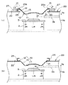
図6は、クランプ装置内に、つまりクランパとディスク受け部の間に、ディスクDbを挿入する直前の状態を示すクランプ装置の断面説明図で、(a)はマグネット27を備えた本発明実施例を示し、(b)はマグネットを備えていない比較例を示している。
図6(a)に示されるように、クランパホルダ上面22上にマグネット27を備えた本発明実施例では、同図において矢印で示す方向の磁力Jcにより、クランパ10の上部に(特に、被保持部12に)浮力が作用しており、この浮力によって、クランパ10は、その被保持部12がガイド部25の上壁25bに当接するまで、矢印Yaの方向へ持ち上げられている。尚、クランパ10には、モータ2内の磁石(不図示)による逆向きの(矢印Yb方向の)磁力Jmが作用しているが、クランパホルダ20がモータ2から所定間隔以上離間した非クランプ状態では、マグネット27による浮力の方が勝るように設定されている。
FIG. 6 is a cross-sectional explanatory view of the clamping device showing a state immediately before the disk Db is inserted in the clamping device, that is, between the clamper and the disk receiving portion. FIG. (B) has shown the comparative example which is not provided with the magnet.
As shown in FIG. 6A, in the embodiment of the present invention having the
このようにクランパ10が浮上した状態であれば、クランパホルダ20とディスク受け部3との間隔が一定でも、クランパ10とディスク受け部3との間隔を、クランパホルダ上面22とガイド部25の上壁25bとの間隔に相当するだけ大きくすることができる。従って、ディスクDbを矢印Yc方向へ移動させてクランパホルダ20とディスク受け部3の間に挿入するに際して、両者20,3を矢印Ya−Yb方向へ相対的に離間させる必要なしに、ディスクDbがクランパホルダ20及び/又はディスク受け部3と接触あるいは干渉することを回避するに足る所要間隔を確保することができる。
In this way, when the
一方、図6(b)に示されるように、クランパホルダ上面22上にマグネット27を備えていない比較例では、図6(a)におけるような浮力をクランパ10に作用させる磁力Jcは生じないので、クランパ10は、その自重および/またはモータ2側の磁力Jmにより、その被保持部12がクランパホルダ上面22に当接するまで、矢印Ybの方向へ下降している。
On the other hand, as shown in FIG. 6B, in the comparative example in which the
このようにクランパ10が下降した状態では、ディスクDbをクランパホルダ20とディスク受け部3の間に挿入しようとすれば、ディスクDbがクランパホルダ20及び/又はディスク受け部3と接触あるいは干渉することとなる。従って、この場合には、このような接触あるいは干渉を回避するに足る距離だけ、クランパ10とディスク受け部3とを矢印Ya−Yb方向へ相対的に離間させる必要がある。つまり、この分だけ、クランプ装置1の矢印Ya−Yb方向サイズを大きくする必要があり、大型化を招くことになる。
In this state where the
しかるに、本発明実施例では、図6(a)に示されるように、クランパ10の上部に(特に、被保持部12に)浮力が作用し、この浮力によって、クランパ10は、その被保持部12がガイド部25の上壁25bに当接するまで、矢印Yaの方向へ持ち上げられており、ディスクDbを矢印Yc方向へ移動させてクランパホルダ20とディスク受け部3の間に挿入するに際して、両者20,3を矢印Ya−Yb方向へ相対的に離間させる必要なしに、ディスクDbがクランパホルダ20及び/又はディスク受け部3と接触あるいは干渉することを回避するに足る所要間隔を確保することができる。
However, in the embodiment of the present invention, as shown in FIG. 6A, buoyancy acts on the upper portion of the clamper 10 (particularly, on the held portion 12), and the buoyancy causes the
すなわち、従来のように、クランパホルダ20でクランパ10を持ち上げて両者の間隔を広げなくても、支障なくディスクDbを挿入することができ、従来に比して、クランプ装置1の小型化を図ることができるのである。
特に、本実施形態では、クランパホルダ20にマグネット27を配設すると共に、クランプホルダ20の少なくとも前記マグネット27を配置した箇所の内側部分を(本実施例では、クランプホルダ20全体を)磁性体で形成するだけの簡単な構成で、磁力を利用してクランパ10を浮上させることができる。
That is, the disk Db can be inserted without any trouble without lifting the
In particular, in the present embodiment, the
図7は、図6(a)に示した本発明実施例に係るクランプ装置内に、つまりクランパとディスク受け部の間に、ディスクDbを挿入した状態を示すクランプ装置の断面説明図である。
この図7の状態は、前述の切換機構(不図示)によってディスクDbのクランプ状態に切り換えられた状態であり、クランパホルダ20と前記ディスク受け部3とが、前記図6(a)の状態に比して、ディスク受け部3の前記回転軸Lmの伸長方向へ相対的に接近するように移動させられている。
FIG. 7 is a cross-sectional explanatory view of the clamping device showing a state in which the disk Db is inserted into the clamping device according to the embodiment of the present invention shown in FIG. 6A, that is, between the clamper and the disk receiving portion.
The state shown in FIG. 7 is a state where the disk Db is clamped by the switching mechanism (not shown), and the
これにより、クランパ10に作用する磁力について、モータ2内の磁石(不図示)による下向きの(矢印Yb方向の)磁力Jmが、マグネット27による上向きの(矢印Ya方向の)磁力よりも大きくなり、ディスクDbがクランパ10とディスク受け部3との間に挟着されるように設定されている。
Thereby, with respect to the magnetic force acting on the
このディスクDbのクランプ状態において、クランパ10の連繋部13は、前記回転軸Lmの伸長方向について何らの変形しておらず、被保持部12と押圧部11とを初期位置に保つようになっている。そして、クランパ10の被保持部12は、ガイド部25の上壁25b及びクランパホルダ上面22の何れにも接触せず、クランプ10支障なく高速回転できるように設定されている。尚、クランパ10の前記被保持部12の外周部とガイド部25の縦壁25aの内面とは、クランパホルダ20の開口部21とモータ2のディスク受け部3とを適切に芯合わせすることにより、互いに接触することがないように設定されている。
In the clamped state of the disk Db, the connecting
図8は、クランプ装置内に、つまりクランパとディスク受け部の間に、内部にブルーレイディスクBDを収納するとともに内蔵クランパ46を内包したBDカートリッジC2を挿入した状態を示すクランプ装置の断面説明図で、(a)は本発明実施例を示し、(b)は比較例を示している。尚、両図で示される何れの例においても、クランパホルダ上面22に、図6(a)で示したものと同様のマグネット27が配設されている。
FIG. 8 is a cross-sectional explanatory view of the clamp device showing a state in which the BD cartridge C2 containing the Blu-ray disc BD and including the built-in
図8(b)に示されるように、比較例のクランパ90では、押圧部91と被保持部92とを連繋する連繋部93は、剛性が高く、ディスク受け部3の回転軸Lmの伸長方向(矢印Ya−Yb方向)について、弾性による伸縮動作を行うことが殆どできない。このため、内蔵クランパ46を内包する関係上厚さ方向のサイズが大きいBDカートリッジC2を挿入するには、その厚さが増す分だけクランパ90を上方に持ち上げて、クランパ90とディスク受け部3とを矢印Ya−Yb方向へ相対的に離間させる必要がある。つまり、この分だけ、クランプ装置1の矢印Ya−Yb方向サイズを大きくする必要があり、大型化を招くことになる。
As shown in FIG. 8B, in the
これに対して、本発明実施例のクランパ10では、図7に示すように、ディスクDbをクランプする際には、連繋部13が被保持部12と押圧部11とを初期位置に保った状態で、当該ディスクDbをクランプしており、連繋部13が弾性範囲内で収縮することにより、被保持部12と押圧部11とを前記回転軸Lmの伸長方向(矢印Ya−Yb方向)に相対的に接近する余地が残されている。
On the other hand, in the
そして、図8(a)に示されるように、厚さ方向のサイズが大きいBDカートリッジC2が挿入された際には、連繋部13が弾性範囲内で収縮することで、クランパ10とディスク受け部3とを矢印Ya−Yb方向へ相対的に離間させる必要なしに、BDカートリッジC2を支障なく挿入することができ、また、その収縮状態で、被保持部12と押圧部11の間に離間方向の付勢力を作用させることができる。
更に、本実施形態では、このBDカートリッジC2が挿入され、内包されたディスクBDがディスク受け部3に載置される際には、前記連繋部13は、BDカートリッジC2の外方に向かって退避しつつ収縮状態となる。この場合、厚さ方向のサイズが大きいBDカートリッジC2をクランプする際に、クランパ10は、連繋部13が収縮状態で、つまり、被保持部12と押圧部11とが前記回転軸Lmの伸長方向に接近し、連繋部13が両者間に離間方向の付勢力を及ぼした状態で当該BDカートリッジC2をクランプするが、連繋部13がBDカートリッジC2の外方に向かって退避しつつ収縮状態となることで、BDカートリッジC2の表面に傷を付けない程度のクランプ力で当該BDカートリッジC2をクランプすることができる。
As shown in FIG. 8A, when the BD cartridge C2 having a large size in the thickness direction is inserted, the connecting
Further, in the present embodiment, when the BD cartridge C2 is inserted and the contained disc BD is placed on the
このように、本発明実施例に係るクランプ装置1によれば、ディスクBDと内蔵クランパ46とを内包したカートリッジC2をクランプする際には、連繋部13が収縮して被保持部12と押圧部11とが前記回転軸Lmの伸長方向(矢印Ya−Yb方向)に相対的に接近することで、有効に対応することができる。すなわち、クランプ装置1の大型化を特に招くことなく、ディスクBDと内蔵クランパ46とを内包した厚いカートリッジC2のクランプ、並びにディスクDbのクランプの両方について、有効に対応することができるのである。
Thus, according to the clamping device 1 according to the embodiment of the present invention, when the cartridge C2 including the disk BD and the built-in
尚、以上の実施形態では、内蔵クランパは内包していないが内部にDVD−RAMディスクDrを収納したRAMカートリッジC1の挿入及びクランパについての具体例は示していないが、この場合には、内蔵クランパを内包していないので、図6(a),(b)及び図7で示したベアディスクDbの場合と実質的同様である。 In the above embodiment, the built-in clamper is not included, but a specific example of the insertion of the RAM cartridge C1 containing the DVD-RAM disk Dr and the clamper is not shown, but in this case, the built-in clamper is not shown. Is substantially the same as that of the bare disk Db shown in FIGS. 6 (a), 6 (b) and 7.
本実施形態に係るディスク装置では、以上のような本発明実施例に係るクランプ装置1が組み込まれることにより、ディスク装置の大型化を特に招くことなく、ディスクBDと内蔵クランパ46とを内包したBDカートリッジC2のクランプ、並びにRAMカートリッジC1内のディスクDr及びベアディスクDbのクランプを行うことができ、或いは、従来に比してディスク装置の小型化を図ることができる。
In the disk apparatus according to the present embodiment, the BD including the disk BD and the built-in
尚、以上の実施形態では、クランパ10は1枚物の板状またはシート状の素材を用いて一体物として構成されているが、押圧部,被保持部及び連繋部の少なくとも何れか一つを別物として製作しておき、これを他の要素と組み立てて接合することによりクランパを構成するようにしても良い。
図9は、本発明の他の実施形態(第2実施形態)に係る組立構造とされたクランパの断面説明図で、(a)は初期状態を示し、(b)は連繋部の収縮状態を示している。
In the above embodiment, the
FIG. 9 is a cross-sectional explanatory view of a clamper having an assembly structure according to another embodiment (second embodiment) of the present invention, where (a) shows an initial state, and (b) shows a contracted state of the connecting portion. Show.
図9(a)及び(b)に示すように、本実施形態に係るクランパ50は、円板状の上板51と、該上板51に周縁部分が固定された中間体52と、該中間体52に対して、矢印Ya−Yb方向へ相対変位可能に保持された可動体60と、上板51と可動体60の間に介装された圧縮バネ70とを備えている。
前記中間体52は、その外周部と内周部に環状のフランジ部53,54を有し、外周フランジ部53の内縁端部と内周フランジ部54の外縁端部とを傾斜面部55で接続して構成されている。そして、外周フランジ部53の上面と上板51の下面とを接合することで、上板51と中間体52とが一体化されている。
As shown in FIGS. 9A and 9B, a
The
前記可動体60は、中間体52の内周フランジ部54に係合される係合フランジ部61と、該係合フランジ部61の内周よりも小径の底板部62とを有し、係合フランジ部61の内縁端部と底板部62の外縁端部とを傾斜面部63で接続して構成されている。
前記圧縮バネ70は、例えば円筒コイル状に形成され、上板51と可動体60の底板部62との間に介装され、両者を互いに離間する方向(矢印Ya−Yb方向)へ付勢している。
The
The
本実施形態に係るクランパ50では、可動体60の底板部62が「クランプ状態でディスクDbをディスク受け部3に押圧する押圧部」に相当し、中間体52の外周フランジ部53が「クランパホルダ20がディスク受け部3から回転軸Lmの伸長方向へ相対的に離間する際にクランパホルダ20に保持される被保持部」に相当し、圧縮バネ70が「被保持部と押圧部とを前記回転軸Lmの伸長方向に相対変位可能に連繋する連繋部」に相当している。
In the
尚、本実施形態に係るクランパ50では、中間体52の内周フランジ部54と可動体60の係合フランジ部61とが係合する場合、内周フランジ部54の内端面54kと、係合フランジ61の直下方で傾斜面部63の外端に位置する外端面63kとが嵌合することになるが、より好ましくは、両者の嵌合面54k,63kは共に、クランパ50の回転軸Lk(回転時は前記ディスク受け部3の回転軸Lmと一致する)と平行をなす円筒面に形成されている。
かかる構成を採用したことにより、前記嵌合部分をテーパ嵌合とする場合に比して、クランパ50の回転時には、遠心力の作用により中間体52と可動体60との位置ずれ(芯ずれ)を有効に規制することができる。
In the
By adopting such a configuration, as compared with the case where the fitting portion is tapered fitting, when the
本発明は、例えば、映像用や音楽用あるいはコンピュータ・データ用等の情報記録媒体としてのディスクを、当該ディスクの記録再生時などにクランプするクランプ装置、及びかかるクランプ装置を備えたディスク装置において利用することができ、ディスク装置の大型化を抑制しつつ、内蔵クランパを内包したカートリッジと内包しないカートリッジ及びベアディスクの何れにも対応してディスクをクランプし記録再生を行うことができ、また、これらディスク或いはカートリッジとクランパとの干渉若しくは擦り合いを確実に回避することができる。 The present invention is used in, for example, a clamp device that clamps a disc as an information recording medium for video, music, computer data, etc., at the time of recording / reproducing the disc, and a disc device provided with such a clamp device. It is possible to perform recording and playback by clamping the disc corresponding to both the cartridge including the built-in clamper, the cartridge not including the built-in clamper, and the bare disc while suppressing an increase in the size of the disc device. Interference or rubbing between the disk or cartridge and the clamper can be reliably avoided.
尚、本発明は、以上の実施態様に限定されるものではなく、その要旨を逸脱しない範囲において、種々の変更や改良を加え得るものであることは言うまでもない。 Needless to say, the present invention is not limited to the above-described embodiments, and various modifications and improvements can be added without departing from the scope of the present invention.
1 クランプ装置
2 モータ
3 ディスク受け部
10,50 クランパ
11 押圧部
12 被保持部
13 連繋部
20 クランパホルダ
22 クランパホルダの上面
25 ガイド部
27 マグネット
46 内蔵クランパ
52 中間体
53 中間体の外周フランジ部
60 可動体
62 可動体の底板部
70 圧縮バネ
BD ブルーレイディスク
C1 RAMカートリッジ
C2 BDカートリッジ
Db ベアディスク
Dr DVDディスク
Lm ディスク受け部の回転軸
DESCRIPTION OF SYMBOLS 1
Claims (7)
前記クランパを前記ディスク受け部の回転軸方向へ移動可能に保持するクランパホルダと、
該クランパホルダと前記ディスク受け部とを前記回転軸方向へ相対的に移動させ、前記クランパホルダと前記ディスク受け部との間に位置するディスクのクランプ状態とクランプ解除状態とを切り換える切換手段と、を備え、
前記クランパは、前記クランプ状態で前記ディスクを前記ディスク受け部に押圧する押圧部と、前記クランパホルダが前記ディスク受け部から前記回転軸方向へ相対的に離間する際に前記クランパホルダに保持される被保持部と、該被保持部と前記押圧部とを前記回転軸方向に相対変位可能に連繋する連繋部とを備えており、
前記クランパは、前記ディスクがクランプされる際には、前記連繋部が前記被保持部と前記押圧部とを初期位置に保った状態でクランプする、
ことを特徴とするクランプ装置。 A clamper that is rotated by the driving force of the motor and that is disposed opposite to a disk receiving portion that receives a disk as an information medium;
A clamper holder for holding the clamper so as to be movable in the direction of the rotation axis of the disk receiving portion;
Switching means for relatively moving the clamper holder and the disk receiving portion in the direction of the rotation axis and switching between a clamped state and a clamp-released state of the disk located between the clamper holder and the disk receiving portion; With
The clamper is held by the clamper holder when the clamper is relatively separated from the disk receiving portion in the rotation axis direction, and a pressing portion that presses the disc against the disc receiving portion in the clamped state. A held portion, and a connecting portion that connects the held portion and the pressing portion so as to be capable of relative displacement in the rotation axis direction,
When the disc is clamped, the clamper clamps the linked portion while maintaining the held portion and the pressing portion at an initial position.
A clamping device characterized by that.
ディスクと内蔵クランパとを内包したカートリッジの前記ディスクがディスク受け部に載置される際には、前記連繋部は、前記カートリッジの外方に向かって退避しつつ収縮状態となる、
ことを特徴とする請求項1記載のクランプ装置。 The connecting portion exerts a biasing force in a separating direction between the both in the contracted state in which the held portion and the pressing portion are close to each other in the rotation axis direction,
When the disc of the cartridge containing the disc and the built-in clamper is placed on the disc receiving portion, the connecting portion is in a contracted state while retracting toward the outside of the cartridge.
The clamping device according to claim 1.
前記クランパを前記ディスク受け部の回転軸方向へ移動可能に保持するクランパホルダと、
該クランパホルダと前記ディスク受け部とを前記回転軸方向へ相対的に移動させ、前記クランパホルダと前記ディスク受け部との間に位置するディスクのクランプ状態とクランプ解除状態とを切り換える切換手段と、を備え、
前記クランパの少なくとも一部は磁性体で形成され、
前記クランパホルダは前記回転軸に直交する平面を有するとともに、前記クランプ解除状態で前記平面内での前記クランパの位置を規制する位置規制手段を備えており、
前記クランパホルダには、前記クランパを前記ディスク受け部に対し離間させる方向へ浮上させるクランパ浮上手段が設けられている、
ことを特徴とするクランプ装置。 A clamper that is rotated by the driving force of the motor and that is disposed opposite to a disk receiving portion that receives a disk as an information medium;
A clamper holder for holding the clamper so as to be movable in the direction of the rotation axis of the disk receiving portion;
Switching means for relatively moving the clamper holder and the disk receiving portion in the direction of the rotation axis and switching between a clamped state and a clamp-released state of the disk located between the clamper holder and the disk receiving portion; With
At least a portion of the clamper is formed of a magnetic material;
The clamper holder has a plane orthogonal to the rotation axis, and includes a position regulating means for regulating the position of the clamper in the plane in the clamp release state.
The clamper holder is provided with clamper levitation means for levitation in the direction of separating the clamper from the disk receiving portion.
A clamping device characterized by that.
前記クランプホルダの少なくとも前記磁石が配置された箇所の内側部分が磁性体で形成されており、該磁性体と前記磁石とで前記クランパ浮上手段が構成されていることを特徴とする請求項3記載のクランプ装置。 On the plane of the clamper holder, a magnet is disposed outside the position restricting means,
4. The clamper levitation means is formed of a magnetic body at least an inner portion of the clamp holder where the magnet is disposed, and the magnetic body and the magnet constitute the clamper levitation means. Clamping device.
前記クランパは、前記ディスクがクランプされる際には、前記連繋部が前記被保持部と前記押圧部とを初期位置に保った状態でクランプする、
ことを特徴とする請求項3又は4に記載のクランプ装置。 The clamper is held by the clamper holder when the clamper is relatively separated from the disk receiving portion in the rotation axis direction, and a pressing portion that presses the disc against the disc receiving portion in the clamped state. A held portion, and a connecting portion that connects the held portion and the pressing portion so as to be capable of relative displacement in the rotation axis direction,
When the disc is clamped, the clamper clamps the linked portion while maintaining the held portion and the pressing portion at an initial position.
The clamping device according to claim 3 or 4, characterized by the above.
ディスクと内蔵クランパとを内包したカートリッジの前記ディスクがディスク受け部に載置される際には、前記連繋部は、前記カートリッジの外方に向かって退避しつつ収縮状態となる、
ことを特徴とする請求項5記載のクランプ装置。 The connecting portion exerts a biasing force in a separating direction between the both in the contracted state in which the held portion and the pressing portion are close to each other in the rotation axis direction,
When the disc of the cartridge containing the disc and the built-in clamper is placed on the disc receiving portion, the connecting portion is in a contracted state while retracting toward the outside of the cartridge.
The clamping device according to claim 5, wherein:
モータの駆動力で回転し前記ディスクを受け合うディスク受け部に対して、前記ディスク又は第2カートリッジを押圧するクランプ装置として、前記請求項1から請求項6の何れか一に記載のクランプ装置を備えたことを特徴とするディスク装置。
A disc device that records and / or reproduces a disc for any of a disc as an information medium, a first cartridge containing a disc, and a second cartridge containing a disc and a built-in clamper,
The clamp device according to any one of claims 1 to 6, wherein the clamp device presses the disc or the second cartridge against a disc receiving portion that rotates by a driving force of a motor and receives the disc. A disk device comprising:
Priority Applications (1)
| Application Number | Priority Date | Filing Date | Title |
|---|---|---|---|
| JP2005319012A JP2007128582A (en) | 2005-11-02 | 2005-11-02 | Clamp device and disk device equipped therewith |
Applications Claiming Priority (1)
| Application Number | Priority Date | Filing Date | Title |
|---|---|---|---|
| JP2005319012A JP2007128582A (en) | 2005-11-02 | 2005-11-02 | Clamp device and disk device equipped therewith |
Publications (1)
| Publication Number | Publication Date |
|---|---|
| JP2007128582A true JP2007128582A (en) | 2007-05-24 |
Family
ID=38151103
Family Applications (1)
| Application Number | Title | Priority Date | Filing Date |
|---|---|---|---|
| JP2005319012A Pending JP2007128582A (en) | 2005-11-02 | 2005-11-02 | Clamp device and disk device equipped therewith |
Country Status (1)
| Country | Link |
|---|---|
| JP (1) | JP2007128582A (en) |
Cited By (2)
| Publication number | Priority date | Publication date | Assignee | Title |
|---|---|---|---|---|
| JP2012033252A (en) * | 2010-06-30 | 2012-02-16 | Panasonic Corp | Disk device |
| JP2013004119A (en) * | 2011-06-13 | 2013-01-07 | Mitsubishi Electric Corp | Disk device and clamp mechanism |
-
2005
- 2005-11-02 JP JP2005319012A patent/JP2007128582A/en active Pending
Cited By (2)
| Publication number | Priority date | Publication date | Assignee | Title |
|---|---|---|---|---|
| JP2012033252A (en) * | 2010-06-30 | 2012-02-16 | Panasonic Corp | Disk device |
| JP2013004119A (en) * | 2011-06-13 | 2013-01-07 | Mitsubishi Electric Corp | Disk device and clamp mechanism |
Similar Documents
| Publication | Publication Date | Title |
|---|---|---|
| JP2010108599A (en) | Actuator for optical pickup | |
| KR100833226B1 (en) | Disk clamping apparatus for disk player | |
| JP3764415B2 (en) | Disc clamping device | |
| JP2007128582A (en) | Clamp device and disk device equipped therewith | |
| JP3690027B2 (en) | Disk drive device and disk holding mechanism | |
| JP2003123314A (en) | Optical disk of high density | |
| EP1473725A1 (en) | Adapter for non-circular disc | |
| JPS6387677A (en) | Disk cartridge | |
| JP4246354B2 (en) | Disk unit | |
| CN101714361B (en) | Turn table for spindle motor | |
| JP3356086B2 (en) | Disc clamping device | |
| JP2008112498A (en) | Optical disk drive and cleaning method of objective lens | |
| JP4137424B2 (en) | Optical disk device | |
| JP2007207369A (en) | Optical disk device | |
| JP2006059484A (en) | Optical disk device | |
| KR20010054103A (en) | Adapter for mounting compact disk with mini disk player and mini disk palyer having the same | |
| KR100760205B1 (en) | Actuator for optical pickup | |
| JP3919171B2 (en) | Objective lens driving device and optical pickup device including the same | |
| JP2655389B2 (en) | Information recording disk centering clamp device | |
| JP2009059459A (en) | Information recording and reproducing apparatus and cap used therefor | |
| JP5097378B2 (en) | Optical disk device | |
| JP3004103U (en) | Disk cartridge adapter | |
| KR100195130B1 (en) | Photo recording/reprodution apparatus | |
| JP2007058905A (en) | Optical disk device | |
| JP5141172B2 (en) | Storage tray |