JP2007122018A - Liquid crystal display device - Google Patents
Liquid crystal display device Download PDFInfo
- Publication number
- JP2007122018A JP2007122018A JP2006218586A JP2006218586A JP2007122018A JP 2007122018 A JP2007122018 A JP 2007122018A JP 2006218586 A JP2006218586 A JP 2006218586A JP 2006218586 A JP2006218586 A JP 2006218586A JP 2007122018 A JP2007122018 A JP 2007122018A
- Authority
- JP
- Japan
- Prior art keywords
- liquid crystal
- light source
- color
- crystal display
- display device
- Prior art date
- Legal status (The legal status is an assumption and is not a legal conclusion. Google has not performed a legal analysis and makes no representation as to the accuracy of the status listed.)
- Pending
Links
Images


Classifications
-
- G—PHYSICS
- G09—EDUCATION; CRYPTOGRAPHY; DISPLAY; ADVERTISING; SEALS
- G09G—ARRANGEMENTS OR CIRCUITS FOR CONTROL OF INDICATING DEVICES USING STATIC MEANS TO PRESENT VARIABLE INFORMATION
- G09G3/00—Control arrangements or circuits, of interest only in connection with visual indicators other than cathode-ray tubes
- G09G3/20—Control arrangements or circuits, of interest only in connection with visual indicators other than cathode-ray tubes for presentation of an assembly of a number of characters, e.g. a page, by composing the assembly by combination of individual elements arranged in a matrix no fixed position being assigned to or needed to be assigned to the individual characters or partial characters
- G09G3/34—Control arrangements or circuits, of interest only in connection with visual indicators other than cathode-ray tubes for presentation of an assembly of a number of characters, e.g. a page, by composing the assembly by combination of individual elements arranged in a matrix no fixed position being assigned to or needed to be assigned to the individual characters or partial characters by control of light from an independent source
- G09G3/3406—Control of illumination source
- G09G3/3413—Details of control of colour illumination sources
-
- G—PHYSICS
- G09—EDUCATION; CRYPTOGRAPHY; DISPLAY; ADVERTISING; SEALS
- G09G—ARRANGEMENTS OR CIRCUITS FOR CONTROL OF INDICATING DEVICES USING STATIC MEANS TO PRESENT VARIABLE INFORMATION
- G09G2300/00—Aspects of the constitution of display devices
- G09G2300/04—Structural and physical details of display devices
- G09G2300/0439—Pixel structures
- G09G2300/0443—Pixel structures with several sub-pixels for the same colour in a pixel, not specifically used to display gradations
-
- G—PHYSICS
- G09—EDUCATION; CRYPTOGRAPHY; DISPLAY; ADVERTISING; SEALS
- G09G—ARRANGEMENTS OR CIRCUITS FOR CONTROL OF INDICATING DEVICES USING STATIC MEANS TO PRESENT VARIABLE INFORMATION
- G09G2300/00—Aspects of the constitution of display devices
- G09G2300/04—Structural and physical details of display devices
- G09G2300/0469—Details of the physics of pixel operation
- G09G2300/0478—Details of the physics of pixel operation related to liquid crystal pixels
- G09G2300/0491—Use of a bi-refringent liquid crystal, optically controlled bi-refringence [OCB] with bend and splay states, or electrically controlled bi-refringence [ECB] for controlling the color
-
- G—PHYSICS
- G09—EDUCATION; CRYPTOGRAPHY; DISPLAY; ADVERTISING; SEALS
- G09G—ARRANGEMENTS OR CIRCUITS FOR CONTROL OF INDICATING DEVICES USING STATIC MEANS TO PRESENT VARIABLE INFORMATION
- G09G2310/00—Command of the display device
- G09G2310/02—Addressing, scanning or driving the display screen or processing steps related thereto
- G09G2310/0235—Field-sequential colour display
-
- G—PHYSICS
- G09—EDUCATION; CRYPTOGRAPHY; DISPLAY; ADVERTISING; SEALS
- G09G—ARRANGEMENTS OR CIRCUITS FOR CONTROL OF INDICATING DEVICES USING STATIC MEANS TO PRESENT VARIABLE INFORMATION
- G09G2310/00—Command of the display device
- G09G2310/06—Details of flat display driving waveforms
- G09G2310/061—Details of flat display driving waveforms for resetting or blanking
- G09G2310/063—Waveforms for resetting the whole screen at once
-
- G—PHYSICS
- G09—EDUCATION; CRYPTOGRAPHY; DISPLAY; ADVERTISING; SEALS
- G09G—ARRANGEMENTS OR CIRCUITS FOR CONTROL OF INDICATING DEVICES USING STATIC MEANS TO PRESENT VARIABLE INFORMATION
- G09G2320/00—Control of display operating conditions
- G09G2320/02—Improving the quality of display appearance
- G09G2320/0242—Compensation of deficiencies in the appearance of colours
-
- G—PHYSICS
- G09—EDUCATION; CRYPTOGRAPHY; DISPLAY; ADVERTISING; SEALS
- G09G—ARRANGEMENTS OR CIRCUITS FOR CONTROL OF INDICATING DEVICES USING STATIC MEANS TO PRESENT VARIABLE INFORMATION
- G09G2320/00—Control of display operating conditions
- G09G2320/02—Improving the quality of display appearance
- G09G2320/0261—Improving the quality of display appearance in the context of movement of objects on the screen or movement of the observer relative to the screen
-
- G—PHYSICS
- G09—EDUCATION; CRYPTOGRAPHY; DISPLAY; ADVERTISING; SEALS
- G09G—ARRANGEMENTS OR CIRCUITS FOR CONTROL OF INDICATING DEVICES USING STATIC MEANS TO PRESENT VARIABLE INFORMATION
- G09G3/00—Control arrangements or circuits, of interest only in connection with visual indicators other than cathode-ray tubes
- G09G3/20—Control arrangements or circuits, of interest only in connection with visual indicators other than cathode-ray tubes for presentation of an assembly of a number of characters, e.g. a page, by composing the assembly by combination of individual elements arranged in a matrix no fixed position being assigned to or needed to be assigned to the individual characters or partial characters
- G09G3/34—Control arrangements or circuits, of interest only in connection with visual indicators other than cathode-ray tubes for presentation of an assembly of a number of characters, e.g. a page, by composing the assembly by combination of individual elements arranged in a matrix no fixed position being assigned to or needed to be assigned to the individual characters or partial characters by control of light from an independent source
- G09G3/36—Control arrangements or circuits, of interest only in connection with visual indicators other than cathode-ray tubes for presentation of an assembly of a number of characters, e.g. a page, by composing the assembly by combination of individual elements arranged in a matrix no fixed position being assigned to or needed to be assigned to the individual characters or partial characters by control of light from an independent source using liquid crystals
- G09G3/3611—Control of matrices with row and column drivers
- G09G3/3648—Control of matrices with row and column drivers using an active matrix
Abstract
Description
この発明は、液晶表示装置に係り、特に、OCB(Optically Compensated Birefringence)モードを適用した液晶表示装置に関する。 The present invention relates to a liquid crystal display device, and more particularly to a liquid crystal display device to which an OCB (Optically Compensated Birefringence) mode is applied.
近年、時分割で異なる色画像を順次に高速表示することで、各色を混色しカラー表示を行うという、いわゆるフィールドシーケンシャル駆動方式の液晶表示装置が提案されている。この液晶表示装置は、時分割でカラー化を行っているため、これまで液晶表示装置のカラー化に不可欠であったカラーフィルタが不要となる。また、1画素で3色の色画像を順次表示する方式であるため、従来の駆動方式に比べて、高精細化、低コスト化、さらには、バックライト光の高利用効率化を実現できる等の利点を有する。 In recent years, a so-called field-sequential drive type liquid crystal display device has been proposed in which different color images are sequentially displayed at a high speed in a time-division manner so that each color is mixed and displayed in color. Since this liquid crystal display device is colorized in a time-sharing manner, a color filter that has been indispensable for the colorization of liquid crystal display devices so far becomes unnecessary. In addition, since the three-color image is sequentially displayed with one pixel, it is possible to realize higher definition, lower cost, and higher utilization efficiency of backlight light compared to the conventional driving method. Has the advantage of
このような駆動方式を採用する場合、1フィールド期間内に少なくとも3色以上の色画像を表示する必要があるため、より高速な応答特性が要求される。このような要求に対して、OCBモードを適用した液晶表示装置が有効である。このOCBモード液晶表示装置は、ネマティック液晶の液晶分子をベンド配列させることにより高速な応答特性を実現することができると期待されている(例えば、特許文献1参照)。
しかしながら、このOCBモード液晶表示装置は、それ単体では良好な黒表示を行うことができず、位相差板などを用いた光学的な補償を行う必要がある。この際、位相差板などの部材は、その波長分散特性が液晶材料とは異なることが多く、全波長領域で完全な光学補償を行うことは極めて困難である。このため、黒画像を表示した際、色味付くといった課題を有している。 However, this OCB mode liquid crystal display device alone cannot perform good black display, and it is necessary to perform optical compensation using a retardation plate or the like. At this time, a member such as a retardation plate often has a wavelength dispersion characteristic different from that of a liquid crystal material, and it is extremely difficult to perform complete optical compensation in the entire wavelength region. For this reason, when displaying a black image, it has the subject of coloring.
この発明は、上述した問題点に鑑みなされたものであって、その目的は、表示品位の良好な液晶表示装置を提供することにある。 The present invention has been made in view of the above-described problems, and an object thereof is to provide a liquid crystal display device with good display quality.
この発明の態様による液晶表示装置は、
時分割で異なる色画像を順次表示し、これら色画像を混色してカラー表示を行う液晶表示装置において、
一対の基板間に液晶層を保持した液晶表示パネルと、
複数色の色光源と、
前記色光源のそれぞれと前記液晶表示パネルとを制御する制御手段と、を備え、
前記制御手段は、黒表示時に前記液晶表示パネルを透過した透過光の着色を低減しつつホワイトバランスを維持するように、透過光が着色する色に発光する前記色光源の1つの時間開口率及び発光輝度を制御することを特徴とする。
A liquid crystal display device according to an aspect of the present invention includes:
In a liquid crystal display device that displays different color images sequentially in a time-sharing manner and performs color display by mixing these color images.
A liquid crystal display panel holding a liquid crystal layer between a pair of substrates;
Multiple color light sources,
Control means for controlling each of the color light sources and the liquid crystal display panel,
The control means includes one temporal aperture ratio of the color light source that emits light in a color that the transmitted light emits so as to maintain white balance while reducing coloring of the transmitted light that has passed through the liquid crystal display panel during black display. The light emission luminance is controlled.
この発明によれば、表示品位の良好な液晶表示装置を提供することができる。 According to the present invention, a liquid crystal display device with good display quality can be provided.
以下、この発明の一実施の形態に係る液晶表示装置について図面を参照して説明する。この実施の形態では、液晶表示装置として、特に、OCB(Optically Compensated Birefringence)モードを適用した液晶表示装置を例に説明する。 A liquid crystal display device according to an embodiment of the present invention will be described below with reference to the drawings. In this embodiment, a liquid crystal display device to which an OCB (Optically Compensated Birefringence) mode is applied will be described as an example of the liquid crystal display device.
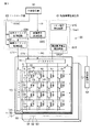
図1に示すように、液晶表示装置は、OCBモードの液晶表示パネル1と、この液晶表示パネル1を照明する面光源装置すなわちバックライトユニット50を備えている。さらに、液晶表示装置は、液晶表示パネル1及びバックライトユニット50を制御する制御手段として機能する表示制御回路60を備えている。
As shown in FIG. 1, the liquid crystal display device includes an OCB mode liquid
液晶表示パネル1は、例えば透過型であり、一対の基板すなわちアレイ基板10と対向基板20との間に液晶層30を保持した構造である。この液晶表示パネル1は、マトリクス状に配置された複数の表示画素PXを備えている。図2に示すように、アレイ基板10は、ガラスなどの光透過性を有する絶縁基板11を用いて形成されている。このアレイ基板10は、絶縁基板11の一方の主面に、表示画素PXの行方向に沿って配置された複数の走査線Y(Y1〜Ym)、表示画素PXの列方向に沿って配置された複数の信号線X(X1〜Xn)、走査線Yと信号線Xとの交差部近傍において表示画素PX毎に配置されたスイッチ素子12、スイッチ素子12に接続され表示画素PX毎に配置された画素電極13、絶縁基板11の主面全体を覆うように配置された配向膜14などを備えている。
The liquid
スイッチ素子12は、例えばTFT(Thin Film Transistor)によって構成されている。各表示画素のスイッチ素子12は、例えばゲートが対応する走査線Yに接続され、ソースが対応する信号線Xに接続され、ドレインが対応する画素電極13に接続されており、対応走査線Yを介して駆動されたときに対応信号線X及び対応画素電極13間で導通する。
The
画素電極13は、例えばITO(Indium Tin Oxide)などの光透過性を有する導電性部材によって形成されている。フロントライト等を用いた反射型の液晶表示パネルを構成するのであれば、画素電極13は、アルミニウム(Al)等の反射材料で構成することができる。そして、画素電極13の表面は、配向膜14によって覆われている。
The
対向基板20は、ガラスなどの光透過性を有する絶縁基板21を用いて形成されている。この対向基板20は、絶縁基板21の一方の主面に対向電極22、配向膜23などを備えている。対向電極22は、複数の表示画素PXに共通に配置され、例えばITOなどの光透過性を有する導電性部材によって形成されている。配向膜23は、絶縁基板21の主面全体を覆うように配置され、光透過性を有する材料によって形成されている。
The
上述したような構成のアレイ基板10と対向基板20とは、図示しないスペーサを介して互いに所定のギャップを維持した状態で配置され、シール材によって貼り合わせられている。液晶層30は、これらアレイ基板10と対向基板20との間のギャップ(例えば、約5μm)に封入されている。液晶層30に含まれる液晶分子31は、正の誘電率異方性を有するとともに光学的に正の一軸性を有する材料(例えば、チッソ社製のMT5623など)を選択可能である。
The
各表示画素PXは、各々画素電極13及び対向電極22間に液晶容量CLCを有している。複数の補助容量線C(C1〜Cm)は、各々対応行の表示画素PXの画素電極13に容量結合して補助容量Csを構成する。
Each display pixel PX has a liquid crystal capacitor CLC between the
このようなOCB型液晶表示装置は、液晶層30に電圧を印加した所定の表示状態において、図1に示したようにベンド配列した液晶分子31を含む液晶層30のリタデーションを光学的に補償する光学補償素子40を備えている。透過型の液晶表示パネル1に対しては、光学補償素子40は、例えば一対で構成されている。すなわち、一方の光学補償素子40は、アレイ基板10の外面に配置され、また、他方の光学補償素子40は、対向基板20の外面に配置されている。これらの光学補償素子40は、それぞれ偏光板や位相差板などを含んで構成されている。
Such an OCB type liquid crystal display device optically compensates for the retardation of the
バックライトユニット50は、アレイ基板10側の光学補償素子40の外側に配置され、複数種類の色光源、例えば3原色の色光源(すなわち赤色に発光する赤色光源51、緑色に発光する緑色光源52、及び、青色に発光する青色光源53)を備えている。この実施の形態では、赤色光源51、緑色光源52、及び、青色光源53は、それぞれ発光ダイオード(LED)によって構成されている。
The
表示制御回路60は、各色画像を表示するフィールド毎に液晶表示パネル1の透過率を制御するとともに、これに同期してバックライトユニット50の色光源の点灯タイミングを制御する機能を有している。
The
すなわち、表示制御回路60は、複数のスイッチ素子12を行単位に導通させるように複数の走査線Y1〜Ymを順次駆動するゲートドライバYD、各行のスイッチ素子12が対応走査線Yの駆動によって導通する期間において画素電圧Vsを複数の信号線X1〜Xnにそれぞれ出力するソースドライバXD、液晶表示パネル1の駆動用電圧を発生する駆動用電圧発生部61、バックライトBLの駆動を制御する光源駆動部62、及び、ゲートドライバYD、ソースドライバXD及び光源駆動部62を制御するコントローラ部63を備えて構成されている。
That is, the
駆動用電圧発生部61は、ゲートドライバYDを介して補助容量線Cに印加される補償電圧Veを発生する補償電圧発生回路6、ソースドライバXDに用いられる所定数の階調基準電圧VREFを発生する階調基準電圧発生回路61T、及び、対向電極22に印加されるコモン電圧Vcomを発生するコモン電圧発生回路61Cを有している。
The driving voltage generation unit 61 generates a compensation
コントローラ部63は、外部信号源SSから入力される同期信号SYNCに基づいてゲートドライバYDに対する制御信号CTYを発生する垂直タイミング制御回路63V、外部信号源SSから入力される同期信号SYNCに基づいてソースドライバXDに対する制御信号CTXを発生する水平タイミング制御回路63H、及び、複数の画素PXに対して外部信号源SSからデジタル形式で入力される映像信号DIを処理する映像信号処理回路63Dを有している。
The controller unit 63 includes a vertical
制御信号CTYは、ゲートドライバYDに供給され、複数の走査線Yを順次駆動する動作をゲートドライバYDに行わせるために用いられる。制御信号CTXは、映像信号処理回路63Dの処理結果と共にソースドライバXDに供給され、映像信号処理回路63Dの処理結果として1行分の表示画素PX単位に得られ直列に出力される映像信号DOを複数の信号線Xにそれぞれ割り当てると共に出力極性を指定する動作をソースドライバXDに行わせるために用いられる。
The control signal CTY is supplied to the gate driver YD and used to cause the gate driver YD to perform an operation of sequentially driving the plurality of scanning lines Y. The control signal CTX is supplied to the source driver XD together with the processing result of the video
ゲートドライバYDは、制御信号CTYの制御により複数の走査線Y1〜Ymを順次選択し、各行の画素スイッチ素子12を導通させる駆動信号としてオン電圧を選択走査線Yに供給する。ソースドライバXDは、上述の階調基準電圧発生回路61Tから供給される所定数の階調基準電圧VREFを参照して映像信号DOをそれぞれ画素電圧Vsに変換し、複数の信号線X1〜Xnに並列的に出力する。
The gate driver YD sequentially selects the plurality of scanning lines Y1 to Ym under the control of the control signal CTY, and supplies an on voltage to the selected scanning line Y as a drive signal for conducting the
画素電圧Vsは、対向電極22のコモン電圧Vcomを基準として画素電極13に印加される電圧であり、例えばフレーム反転駆動およびライン反転駆動を行うようコモン電圧Vcomに対して極性反転される。
The pixel voltage Vs is a voltage applied to the
光源駆動部62は、垂直タイミング制御回路63Vから出力される制御信号CTYに基づいて色画像のフィールド毎に対応する色に発光する色光源を順次発光させる。また、この光源駆動部62は、各色光源に供給する電流量を制御することにより、発光輝度を制御している。
The
上述した液晶表示装置は、時分割で異なる色画像を高速表示することで、これら色画像を混色してカラー表示を行うという、いわゆるフィールドシーケンシャル駆動方式を採用している。このフィールドシーケンシャル駆動方式を簡単に説明すると、バックライトユニット50は、光源駆動部62の制御に基づき、1フレーム期間を3フィールドに分割し、各フィールド期間(1/3フレームの時間)をそれぞれの色光源の発光期間とする。つまり、バックライトユニット50は、発光期間毎に赤色光源(R)51、緑色光源(G)52、青色光源(B)53を順次発光させ、これらの各色光源からの光で液晶表示パネル1を照明する。液晶表示パネル1の透過率は、表示制御回路60の制御に基づき、バックライトユニット50の各色光源の発光に同期して制御され、対応する色画像を順次表示する。このように、液晶表装置は、各色光源からの光に対してその透過率を可変することによりカラー表示が可能である。
The above-described liquid crystal display device employs a so-called field sequential drive system in which different color images are displayed at high speed in a time-sharing manner and these color images are mixed to perform color display. Briefly explaining this field sequential driving method, the
フィールドシーケンシャル駆動方式とOCBモードとを組み合わせた液晶表示装置における動作概念について説明する。なお、液晶表示パネル1は、表示制御回路60の制御に基づき、動画応答性の良化とベンド配列の維持とを目的として、一定期間の黒画像表示を行う黒挿入駆動を行うものとする。また、バックライトユニット50は、各色光源の発光期間が1/3フレーム期間に設定されている。ここでは、各色画像について、すなわち、各色光源が発光する1/3フレーム期間毎に等期間の黒挿入駆動を行った場合について説明する。
An operation concept in a liquid crystal display device combining a field sequential driving method and an OCB mode will be described. The liquid
例えば、図3に示すように、表示制御回路60は、赤色光源51が発光している1/3フレーム期間において、赤色光を透過可能とするオン期間ONr及び透過不能とするオフ期間(黒挿入期間)OFFrを所定の割合で有するように液晶表示パネル1の駆動を制御する。同様に、緑色光源52が発光している1/3フレーム期間も、緑色光を透過可能とするオン期間ONg及び透過不能とするオフ期間(黒挿入期間)OFFgを所定の割合で有しており、また、青色光源53が発光している1/3フレーム期間も、青色光を透過可能とするオン期間ONb及び透過不能とするオフ期間(黒挿入期間)OFFbを所定の割合で有している。
For example, as shown in FIG. 3, in the 1/3 frame period in which the
各1/3フレーム期間においても、オン期間とオフ期間との割合は基本的に同一であり、液晶表示パネル1の透過率を制御することにより、透過光量を制御し、所定の色を再現している。なお、黒画像を再現する際には、各1/3フレーム期間のいずれのオン期間においても透過率を実質的にゼロとすることにより、1フレームの全期間でオフ期間となる。
In each 1/3 frame period, the ratio between the on period and the off period is basically the same. By controlling the transmittance of the liquid
図3に示した例においては、白画像を表示した際に、所望のホワイトバランスが得られるように液晶表示パネル1からの透過光量が調整されている。つまり、透過光量は、色光源の発光輝度、液晶表示パネル1のオン期間、及び、液晶表示パネル1の透過率を乗じた値として定義できる。白画像を表示する際の液晶表示パネル1の透過率を実質的に100%とすると、表示制御回路60によって制御される液晶表示パネル1のオン期間、及び、光源駆動部62によって制御される各色光源の発光輝度により、所定のホワイトバランスが得られるように制御されている。
In the example shown in FIG. 3, the amount of light transmitted from the liquid
このように、液晶表示パネル1は、各色光源が発光している各1/3フレーム期間においてオン期間及びオフ期間を有するように駆動され、透過光特性をインパルス型にすることで動画特性の良化とベンド配列の維持とを両立している。したがって、OCBモードの高速応答を生かしたカラー表示が可能となる。
As described above, the liquid
しかしながら、OCBモードの液晶表示装置は、光学補償素子を用いた光学補償により黒画像を再現しているが、位相差板などの波長分散特性などの影響により、カラー表示に利用される全波長領域で完全な光学補償を行うことは困難である。このため、黒画像を再現した際に光学補償の不十分な波長の光が他の波長の光よりも液晶表示パネル1から多く漏れ出ることになり、その結果、黒画像が色味づくことがある。例えば、図3に示した例では、青色波長の光が他の波長の光よりも液晶表示パネル1から多く漏れ出た場合を示しており、その結果、黒画像が青色に着色する。
However, the OCB mode liquid crystal display device reproduces a black image by optical compensation using an optical compensation element. However, due to the influence of wavelength dispersion characteristics such as a phase difference plate, the entire wavelength region used for color display. Therefore, it is difficult to perform complete optical compensation. For this reason, when reproducing a black image, light having a wavelength with insufficient optical compensation leaks from the liquid
そこで、この実施の形態では、バックライトユニット50から液晶表示パネル1を透過した透過光で所定のホワイトバランスを得るのに必要な各色光源の発光輝度を基準輝度とし、各色光源からの光を透過する液晶表示パネル1の時間開口率を基準開口率としたとき、表示制御回路60は、不所望な着色のない黒色を得るように所定の色光源の発光輝度を基準輝度とは異ならせ、且つ、所定の色光源からの光を透過する際の液晶表示パネル1の時間開口率を基準開口率とは異ならせている。つまり、表示制御回路60は、黒表示時に液晶表示パネル1を透過した透過光の着色を低減しつつ良好なホワイトバランスを維持するように、透過光が着色する色に発光する色光源の時間開口率及び発光輝度を制御する。なお、ここでの時間開口率とは、各色光源が発光する期間(例えば1/3フレーム期間)に対するオン期間の占める割合である。
Therefore, in this embodiment, the light emission luminance of each color light source necessary for obtaining a predetermined white balance with the transmitted light transmitted from the
例えば、図3に示した例のように、黒画像が青みづく場合、図4に示すように、表示制御回路60は、光源駆動部62により青色光源53の発光輝度を基準輝度より低く設定するとともに、駆動用電圧発生部61及びコントローラ部63により青色光源53からの光を透過する際の液晶表示パネル1の時間開口率を基準開口率より大きく設定する。
For example, when the black image becomes bluish as in the example illustrated in FIG. 3, the
つまり、青色光源53の発光輝度を基準輝度より低く設定することにより、光学補償素子40により青色波長の光に対する光学補償が不十分であったとしても、液晶表示パネル1から漏れ出る光量を他の波長の色と同等にすることができる。このため、図3に示した例のように青色光源53を基準輝度で発光させた場合に生じた黒画像の青色の着色が抑制され、良好な黒色を得ることが可能となる。
That is, by setting the light emission luminance of the blue
このように青色光源53の発光輝度を基準輝度よりも低く設定した場合、液晶表示パネル1の時間開口率を基準開口率に設定してしまう(例えば、青色画像を表示するための時間開口率と他の色画像を表示するための時間開口率を同一に設定する)と、青色波長の光量が不足し、ホワイトバランスがずれてしまう。そこで、表示制御回路60は、青色光源53が発光している期間において、液晶表示パネル1のオン期間ONbを図3に示した例よりも長く設定している。これにより、青色光源53からの光を透過する際の液晶表示パネル1の時間開口率が基準開口率より長くなる。
When the emission luminance of the blue
このように、青色光源53の発光輝度と液晶表示パネル1の時間開口率とを制御することにより、青色光源53について基準輝度で発光させ、且つ、液晶表示パネル1を青色光源53が発光している期間に基準開口率で駆動した場合と同等の透過光量を得ることができる。したがって、図3に示した例のようにして駆動したときと同様に、所望のホワイトバランスを得ることができる。
In this way, by controlling the light emission luminance of the blue
なお、ここで、所望のホワイトバランスを得るということは、それぞれ適正な色度に相当することを意味し、そのための一手法として、相関色温度が等しくなる(黒色の相関色温度と白色の相関色温度とが例えば10000Kで略等しくなる)ように各色光源の透過光量を調整すればよい。 Here, obtaining a desired white balance means that each corresponds to an appropriate chromaticity, and as one method for that purpose, the correlated color temperatures are equal (the correlated color temperature of black and the correlated white color). The transmitted light amount of each color light source may be adjusted so that the color temperature is substantially equal at, for example, 10,000 K).
透過光量を調整するためには、表示制御回路60により、各色光源の発光輝度が制御される。特に、各色光源が発光ダイオードによって構成されている場合、各色光源に供給する電流量によって発光輝度を制御すればよい。例えば、図3に示した例のように、赤色フィールド、緑色フィールド、及び、青色フィールドを等期間に設定し、且つ、時間開口率を同一に設定した場合、所定のホワイトバランスを得るのに必要な各色光源の発光輝度(基準輝度)は以下の通りである。すなわち、赤色光源51については80cd/m2の発光輝度とするためにピーク電流量を400mAに設定し、緑色光源52については200cd/m2の発光輝度とするためにピーク電流量を500mAに設定し、青色光源53については20cd/m2の発光輝度とするためにピーク電流量を400mAに設定している。
In order to adjust the amount of transmitted light, the
これに対して、図4に示した例のように、黒画像の青色の着色を改善するために青色フィールドにおける時間開口率を他の色フィールドにおける時間開口率より大きく設定した場合(つまり、青色フィールドにおける時間開口率を基準開口率より大きく設定した場合)、赤色光源51及び緑色光源52については上述の通りの発光輝度とする一方で、所定のホワイトバランスを得るのに必要な青色光源53の発光輝度は17.5cd/m2とし、この発光輝度を得るためにピーク電流量を350mAに設定している。
On the other hand, as in the example shown in FIG. 4, in order to improve the blue coloration of the black image, the time aperture ratio in the blue field is set larger than the time aperture ratio in the other color fields (that is, blue When the time aperture ratio in the field is set to be larger than the reference aperture ratio), the
また、透過光量を調整するためには、表示制御回路60により、液晶表示パネル1の各色光源が発光している期間における時間開口率が制御される。特に、各色光源が発光している期間内に黒挿入期間を有するような駆動方式においては、黒挿入期間によって時間開口率を調整すればよい。例えば、上述した実施の形態のように、黒画像が青色に着色する場合、青色フィールドにおける時間開口率を他の色フィールドにおける時間開口率より大きく設定する。図3に示した例のように、各色光源の時間開口率が同一である(例えば50%である)場合、青色の着色を改善するためには、図4に示した例のように、赤色光源51及び緑色光源52の時間開口率を同一(50%)に維持する一方で、青色光源53の時間開口率を他の色光源の時間開口率より大きく設定し、例えば、57%とする。このような時間開口率の制御は、各色光源の発光に同期して表示される色画像のそれぞれのフィールド期間を同一に設定した場合、つまり、各色光源の発光期間を同一に設定した場合には、オフ期間すなわち黒挿入期間によって調整可能である。すなわち、このような例の場合には、青色フィールド期間における黒挿入期間を、赤色フィールド期間及び緑色フィールド期間における黒挿入期間よりも短く設定することで、青色光源53の時間開口率を赤色光源51及び緑色光源52の時間開口率よりも大きく設定することができる。
In order to adjust the amount of transmitted light, the
なお、時間開口率の制御は、上述したように黒挿入期間によって行う例に限らない。例えば、黒画像が青色に着色する場合、青色光源53の発光に同期して表示される青色画像のフィールド期間を、他の色光源に同期して表示される色画像のフィールド期間より長く設定した場合、各フィールド期間における黒挿入期間を同一に設定しても、青色光源53の時間開口率を他の色光源の時間開口率よりも大きく設定できる。
Note that the control of the time aperture ratio is not limited to the example performed by the black insertion period as described above. For example, when the black image is colored blue, the field period of the blue image displayed in synchronization with the light emission of the blue
すなわち、図5に示した例では、説明を簡略化するために10倍速駆動の場合を例に、黒画像の青色着色を低減する補正方法について説明する。すなわち、1フレームにおいて、3/10フレーム期間が赤色フィールド期間に割り当てられ、また、3/10フレーム期間が緑色フィールド期間に割り当てられ、さらに、4/10フレーム期間が青色フィールド期間に割り当てられる。表示制御回路60は、赤色光源51について赤色フィールド期間(3/10フレーム期間)に合わせて点灯させ、また、緑色光源52について緑色フィールド期間(3/10フレーム期間)に合わせて点灯させ、さらに、青色光源53について青色フィールド期間(4/10フレーム期間)に合わせて点灯させる。つまり、青色光源53を発光させる発光期間は、他の色光源を発光させる発光期間よりも長く設定されている。
That is, in the example shown in FIG. 5, a correction method for reducing blue coloring of a black image will be described by taking a case of 10 × speed driving as an example in order to simplify the description. That is, in one frame, the 3/10 frame period is assigned to the red field period, the 3/10 frame period is assigned to the green field period, and the 4/10 frame period is assigned to the blue field period. The
一方で、液晶表示パネル1においては、各色のフィールド期間において、1フレームにおける1/10フレーム期間を黒挿入期間として割り当てられる。表示制御回路60は、各黒挿入期間において液晶表示パネル1に黒画像を書き込むように駆動する。つまり、表示制御回路60は、赤色フィールド期間及び緑色フィールド期間において、最初の1/10フレーム期間において液晶表示パネル1に黒画像を書き込んだ後、続く1/10フレーム期間において液晶表示パネル1にそれぞれ赤又は緑信号画像を書き込み、さらに、続く1/10フレーム期間において書き込んだ赤又は緑信号画像をそれぞれ保持するように駆動する。これに対して、表示制御回路60は、青色フィールド期間においては、最初の1/10フレーム期間において液晶表示パネル1に黒画像を書き込んだ後、続く1/10フレーム期間において液晶表示パネル1に青信号画像を書き込み、さらに、続く2/10フレーム期間において書き込んだ青信号画像を保持するように駆動する。
On the other hand, in the liquid
これと同時に、表示制御回路60は、青色光源53の発光輝度を低減している。
At the same time, the
つまりこのような10倍速駆動においては、黒画像の青色着色を補正するために、青色フィールド期間を他の色のフィールド期間より長く設定し(つまり、青色光源の発光期間を他の色光源の発光期間より長く設定し)、且つ、各色のフィールド期間における黒挿入期間は同一に設定している。これにより、青色光源に対する時間開口率(75%)が他の色光源に対する時間開口率(66%)よりも大きく設定される。 That is, in such 10 × speed driving, in order to correct the blue coloration of the black image, the blue field period is set longer than the other color field periods (that is, the light emission period of the blue light source is set to the light emission of the other color light source). The black insertion period in each color field period is set to be the same. Thereby, the time aperture ratio (75%) for the blue light source is set larger than the time aperture ratio (66%) for the other color light sources.
なお、1フレームにおいて、すべての色のフィールド期間が3/9フレーム期間に割り当てられ、且つ、各色のフィールド期間において1/9フレーム期間を黒挿入期間として割り当てた(つまり、すべての色光源に対する時間開口率を66%とした)9倍速駆動のとき、所定のホワイトバランスを得るのに必要な青色光源53の発光輝度は20cd/m2であった。これに対して、上述した10倍速駆動の場合には、青色光源53の発光輝度は、17.5cd/m2とし、この発光輝度を得るためにピーク電流量を350mAに設定している。
In one frame, all color field periods are assigned to 3/9 frame periods, and in each color field period, 1/9 frame period is assigned as a black insertion period (that is, time for all color light sources). When driving at 9 × speed (with an aperture ratio of 66%), the light emission luminance of the blue
このような構成により、黒表示時に液晶表示パネルを透過した透過光の着色を低減しつつホワイトバランスを維持することが可能となり、表示品位の良好な液晶表示装置を提供することができる。 With such a configuration, it is possible to maintain white balance while reducing coloring of transmitted light transmitted through the liquid crystal display panel during black display, and it is possible to provide a liquid crystal display device with good display quality.
上述した説明においては、説明を簡略化するために10倍速駆動の例を挙げたが、透過光量の最適化、バックライトユニットにおける各色光源の発光効率、駆動の簡素化などを考慮すると、9.2乃至9.8倍速駆動であることが望ましい。 In the above description, in order to simplify the description, an example of 10 × speed driving was given. However, considering optimization of the amount of transmitted light, light emission efficiency of each color light source in the backlight unit, simplification of driving, etc., 9. It is desirable that the driving speed is 2 to 9.8 times.
上述した実施の形態では、1フレームを1つの赤色フィールド期間、1つの緑色フィールド期間、及び、1つの青色フィールド期間の合計3フィールドによって構成したが、1フレームを4以上のフィールドによって構成してもよい。例えば、高倍速駆動した際に、特定の色に対する色割れ(color breakup)が主観的に視認される場合、その特定の色以外の色のフィールド数を増やして、実質的に1フレームにおける特定の色画像の表示の割合を低下させ、色割れを低減する技術がある(例えば、特開2003−287733号公報参照)。この技術によれば、光源の発光強度を赤成分:緑成分:青成分=1:1:1で白色に設定すると、赤成分は1フィールドとし、緑成分は2つのフィールドに0.5ずつ分配し、青成分も2つのフィールドに0.5ずつ分配し、例えばR:G:Bの輝度比が3:6:1で200cd/m2相当の白色輝度を出力する場合、赤フィールドは60cd/m2、緑フィールドは60cd/m2、青フィールドは10cd/m2に設定する例などが開示されている。しかしながら、OCBモードを適用した液晶表示装置においては、光学補償上の問題などから黒画像を表示した際の特定の色への着色といった問題は残る。 In the above-described embodiment, one frame is constituted by a total of three fields of one red field period, one green field period, and one blue field period. However, one frame may be constituted by four or more fields. Good. For example, when a color breakup for a specific color is visually perceived when driving at a high speed, the number of fields of colors other than the specific color is increased, and a specific break in one frame is substantially achieved. There is a technique for reducing the color image display ratio and reducing color breakup (see, for example, Japanese Patent Application Laid-Open No. 2003-287733). According to this technology, when the light emission intensity of the light source is set to white with red component: green component: blue component = 1: 1: 1, the red component is one field, and the green component is distributed by 0.5 to two fields. When the blue component is also distributed to the two fields by 0.5, for example, when the luminance ratio of R: G: B is 3: 6: 1 and white luminance equivalent to 200 cd / m 2 is output, the red field is 60 cd / An example is disclosed in which m 2 , the green field is set to 60 cd / m 2 , and the blue field is set to 10 cd / m 2 . However, in the liquid crystal display device to which the OCB mode is applied, there remains a problem of coloring to a specific color when displaying a black image due to a problem in optical compensation.
そこで、黒画像の着色の低減とともに色割れを改善するための例として、以下のように、1フレームを4以上のフィールドによって構成することが考えられる。ここでは、黒画像の青色の着色を低減するために、青色光源の発光輝度及び時間開口率を制御するとともに、赤色の色割れを改善するために、1フレームにおける赤色画像の表示割合を低下させる例について説明する。 Therefore, as an example for improving the color breakup while reducing the coloring of the black image, it is conceivable that one frame is composed of four or more fields as follows. Here, in order to reduce the blue coloration of the black image, the emission luminance of the blue light source and the time aperture ratio are controlled, and in order to improve the red color breakup, the display ratio of the red image in one frame is reduced. An example will be described.
すなわち、図6には、12倍速駆動の4フィールド構成の場合を示している。すなわち、1フレームにおいて、3/12フレーム期間に相当する赤色フィールド期間、3/12フレーム期間に相当する青色フィールド期間、3/12フレーム期間に相当する緑色フィールド期間、及び、3/12フレーム期間に相当する青色フィールド期間が順次割り当てられている。表示制御回路60は、赤色光源51について赤色フィールド期間(3/12フレーム期間)に合わせて点灯させた後、青色光源53について第1の青色フィールド期間(3/12フレーム期間)に合わせて点灯させ、これに続いて、緑色光源52について緑色フィールド期間(3/12フレーム期間)に合わせて点灯させた後、さらに、青色光源53について第2の青色フィールド期間(3/12フレーム期間)に合わせて点灯させる。つまり、1フレームにおける青色光源53を発光させる発光期間(6/12フレーム期間)は、他の色光源をそれぞれ発光させる発光期間(3/12フレーム期間)よりも長く設定されている。
That is, FIG. 6 shows the case of a four-field configuration of 12 × speed driving. That is, in one frame, a red field period corresponding to a 3/12 frame period, a blue field period corresponding to a 3/12 frame period, a green field period corresponding to a 3/12 frame period, and a 3/12 frame period Corresponding blue field periods are assigned sequentially. The
一方で、液晶表示パネル1においては、各色のフィールド期間において、1フレームにおける1/12フレーム期間を黒挿入期間として割り当てられる。表示制御回路60は、各黒挿入期間において液晶表示パネル1に黒画像を書き込むように駆動する。つまり、1フレームにおいて、青色光源53に対する時間開口率は、赤色光源51及び緑色光源52に対する時間開口率よりも大きくなる。
On the other hand, in the liquid
これと同時に、表示制御回路60は、青色光源53の発光輝度を低減している。例えばR:G:Bの輝度比が3:6:1で200cd/m2相当の白色輝度を出力する場合、赤フィールドにおける赤色光源51の発光輝度は60cd/m2、緑フィールドにおける緑色光源52の発光輝度は120cd/m2、青フィールドにおける青色光源53の発光輝度は10cd/m2に設定される。
At the same time, the
また、図7には、15倍速駆動の5フィールド構成の場合を示している。すなわち、1フレームにおいて、3/15フレーム期間に相当する赤色フィールド期間、3/15フレーム期間に相当する緑色フィールド期間、3/15フレーム期間に相当する青色フィールド期間、3/15フレーム期間に相当する緑色フィールド期間、及び、3/15フレーム期間に相当する青色フィールド期間が順次割り当てられている。表示制御回路60は、赤色光源51について赤色フィールド期間(3/15フレーム期間)に合わせて点灯させた後、緑色光源52について第1の緑色フィールド期間(3/15フレーム期間)に合わせて点灯させ、その後、青色光源53について第1の青色フィールド期間(3/15フレーム期間)に合わせて点灯させ、これに続いて、緑色光源52について第2の緑色フィールド期間(3/15フレーム期間)に合わせて点灯させた後、さらに、青色光源53について第2の青色フィールド期間(3/15フレーム期間)に合わせて点灯させる。つまり、1フレームにおける緑色光源52及び青色光源53を発光させる発光期間(6/15フレーム期間)は、赤色光源51をそれぞれ発光させる発光期間(3/15フレーム期間)よりも長く設定されている。
FIG. 7 shows the case of a 15-field drive 5-field configuration. That is, in one frame, a red field period corresponding to a 3/15 frame period, a green field period corresponding to a 3/15 frame period, a blue field period corresponding to a 3/15 frame period, and a 3/15 frame period. A green field period and a blue field period corresponding to a 3/15 frame period are sequentially assigned. The
一方で、液晶表示パネル1においては、各色のフィールド期間において、1フレームにおける1/15フレーム期間を黒挿入期間として割り当てられる。表示制御回路60は、各黒挿入期間において液晶表示パネル1に黒画像を書き込むように駆動する。つまり、1フレームにおいて、青色光源53及び緑色光源52に対する時間開口率は、赤色光源51に対する時間開口率よりも大きくなる。
On the other hand, in the liquid
これと同時に、表示制御回路60は、青色光源53の発光輝度を低減している。例えばR:G:Bの輝度比が3:6:1で200cd/m2相当の白色輝度を出力する場合、赤フィールドにおける赤色光源51の発光輝度は60cd/m2、緑フィールドにおける緑色光源52の発光輝度は60cd/m2、青フィールドにおける青色光源53の発光輝度は10cd/m2に設定される。
At the same time, the
これらの図6及び図7に示したような構成によれば、黒表示時に液晶表示パネルを透過した透過光の着色を低減しつつホワイトバランスを維持することが可能となることに加えて、特定の色の色割れを改善することができ、さらに表示品位の良好な液晶表示装置を提供することができる。 According to the configuration shown in FIGS. 6 and 7, it is possible to maintain white balance while reducing coloring of transmitted light transmitted through the liquid crystal display panel during black display. Can be improved, and a liquid crystal display device with good display quality can be provided.
なお、この発明は、上記実施形態そのままに限定されるものではなく、その実施の段階ではその要旨を逸脱しない範囲で構成要素を変形して具体化できる。また、上記実施形態に開示されている複数の構成要素の適宜な組み合せにより種々の発明を形成できる。例えば、実施形態に示される全構成要素から幾つかの構成要素を削除してもよい。更に、異なる実施形態に亘る構成要素を適宜組み合せてもよい。 Note that the present invention is not limited to the above-described embodiment as it is, and can be embodied by modifying the constituent elements without departing from the spirit of the invention in the stage of implementation. In addition, various inventions can be formed by appropriately combining a plurality of constituent elements disclosed in the embodiment. For example, some components may be deleted from all the components shown in the embodiment. Furthermore, you may combine suitably the component covering different embodiment.
上述した実施の形態では、青色波長の光が他の波長の光より多く漏れ出たために生じた黒色の色づきといった課題に対して、青色光源53の発光輝度を低減することで改善したが、逆に、他の色光源すなわち赤色光源51及び緑色光源52の発光輝度を増大することにより液晶表示パネル1から漏れ出る光量を各色間で同等とし、黒色の色づきを改善することも可能である。この場合、ホワイトバランスは青色が不足する方向にずれるため、液晶表示パネル1において、青色光源53が発光している期間の時間開口率を基準開口率よりも長く設定する、あるいは、赤色光源51及び緑色光源52が発光している期間の時間開口率を基準開口率よりも短く設定することにより、所定のホワイトバランスを得ることが可能である。
In the above-described embodiment, the problem of coloring the black color caused by leakage of light of blue wavelength more than light of other wavelengths has been improved by reducing the light emission luminance of the blue
また、上述した実施の形態では、黒画像が青色に着色する場合の補正方法について検討したが、黒画像が緑色や赤色に着色する場合であっても、着色する色に発光する色光源の時間開口率及び発光輝度を制御することにより、同様の補正が可能であり、同等の効果が得られることはいうまでもない。 In the above-described embodiment, the correction method in the case where the black image is colored in blue was examined. However, even when the black image is colored in green or red, the time of the color light source that emits light to the color to be colored It goes without saying that the same correction can be performed by controlling the aperture ratio and the light emission luminance, and the same effect can be obtained.
さらに、上述した実施の形態においては、赤色フィールド、緑色フィールド、及び、青色フィールドによって1フレームを構成する場合について説明したが、これらの3原色のフィールドに加えて白色(つまり、赤色光源、緑色光源、及び、青色光源を同時に点灯するフィールド)のフィールドを加えて1フレームを構成してもよい。また、加法混色の3原色を利用する例に限らず、減法三原色を利用したフィールドすなわちシアンフィールド(緑色光源と青色光源とを同時に点灯するフィールド)、マゼンタフィールド(赤色光源と青色光源とを同時に点灯するフィールド)、及び、イエローフィールド(緑色光源と赤色光源とを同時に点灯するフィールド)によって1フレームを構成してもよい(さらに、必要に応じて黒フィールドを加えてもよい)。また、加法三原色(赤、緑、青)のうちの少なくとも1色のフィールドと、減法三原色(シアン、マゼンタ、イエロー)のうちの少なくとも1色のフィールドとを組み合わせて1フレームを構成してもよい。 Further, in the above-described embodiment, the case where one frame is constituted by the red field, the green field, and the blue field has been described. However, in addition to these three primary color fields, white (that is, a red light source, a green light source) And a field in which a blue light source is simultaneously turned on) may be added to form one frame. Also, the field is not limited to the case of using three additive primary colors, but a field using subtractive three primary colors, that is, a cyan field (a green light source and a blue light source are turned on simultaneously), a magenta field (a red light source and a blue light source are turned on simultaneously). 1 frame) and a yellow field (a field in which a green light source and a red light source are turned on simultaneously) may constitute one frame (a black field may be added if necessary). Further, one frame may be formed by combining a field of at least one of the additive three primary colors (red, green, and blue) and a field of at least one of the subtractive three primary colors (cyan, magenta, and yellow). .
PX…表示画素、Y…走査線、X…信号線、1…液晶表示パネル、10…アレイ基板、20…対向基板、30…液晶層、40…光学補償素子、50…バックライトユニット、51…赤色光源、52…緑色光源、53…青色光源、60…表示制御回路、61…駆動用電圧発生部、62…光源駆動部、63…コントローラ部 PX: display pixel, Y: scanning line, X: signal line, 1 ... liquid crystal display panel, 10 ... array substrate, 20 ... counter substrate, 30 ... liquid crystal layer, 40 ... optical compensation element, 50 ... backlight unit, 51 ... Red light source, 52 ... green light source, 53 ... blue light source, 60 ... display control circuit, 61 ... drive voltage generator, 62 ... light source drive, 63 ... controller unit
Claims (14)
一対の基板間に液晶層を保持した液晶表示パネルと、
複数色の色光源と、
前記色光源のそれぞれと前記液晶表示パネルとを制御する制御手段と、を備え、
前記制御手段は、黒表示時に前記液晶表示パネルを透過した透過光の着色を低減しつつホワイトバランスを維持するように、透過光が着色する色に発光する前記色光源の1つの時間開口率及び発光輝度を制御することを特徴とする液晶表示装置。 In a liquid crystal display device that displays different color images sequentially in a time-sharing manner and performs color display by mixing these color images.
A liquid crystal display panel holding a liquid crystal layer between a pair of substrates;
Multiple color light sources,
Control means for controlling each of the color light sources and the liquid crystal display panel,
The control means includes one temporal aperture ratio of the color light source that emits light in a color that the transmitted light emits so as to maintain white balance while reducing coloring of the transmitted light that has passed through the liquid crystal display panel during black display. A liquid crystal display device characterized by controlling light emission luminance.
黒表示時に前記液晶表示パネルを透過した透過光が前記第1色光源の色に着色するとき、前記制御手段は、前記第1色光源の時間開口率を前記第2色光源の時間開口率より大きく設定することを特徴とする請求項1に記載の液晶表示装置。 The color light source includes a first color light source and a second color light source that emits light in a color different from the first color light source,
When the transmitted light that has passed through the liquid crystal display panel during black display is colored in the color of the first color light source, the control means sets the time aperture ratio of the first color light source from the time aperture ratio of the second color light source. The liquid crystal display device according to claim 1, wherein the liquid crystal display device is set large.
一対の基板間に液晶層を保持した液晶表示パネルと、
赤色光源、緑色光源、及び、青色光源を備え、前記液晶表示パネルを順次各色光源で照明する面光源装置と、
前記面光源装置から前記液晶表示パネルを透過した透過光で所定のホワイトバランスを得るのに必要な各色光源の発光輝度を基準輝度とし、各色光源からの光を透過する前記液晶表示パネルの時間開口率を基準開口率としたとき、所定のホワイトバランスの黒色を得るように所定の色光源の発光輝度を基準輝度とは異ならせ、且つ、前記所定の色光源からの光を透過する際の前記液晶表示パネルの時間開口率を基準開口率とは異ならせる制御手段と、
を備えたことを特徴とする液晶表示装置。 In a liquid crystal display device that displays different color images sequentially in a time-sharing manner and performs color display by mixing these color images.
A liquid crystal display panel holding a liquid crystal layer between a pair of substrates;
A surface light source device comprising a red light source, a green light source, and a blue light source, and sequentially illuminating the liquid crystal display panel with each color light source;
A time aperture of the liquid crystal display panel that transmits light from each color light source with reference to the emission luminance of each color light source necessary for obtaining a predetermined white balance with the transmitted light transmitted from the surface light source device through the liquid crystal display panel When the ratio is a reference aperture ratio, the emission luminance of the predetermined color light source is different from the reference luminance so as to obtain black with a predetermined white balance, and the light from the predetermined color light source is transmitted. Control means for making the time aperture ratio of the liquid crystal display panel different from the reference aperture ratio;
A liquid crystal display device comprising:
Priority Applications (3)
| Application Number | Priority Date | Filing Date | Title |
|---|---|---|---|
| JP2006218586A JP2007122018A (en) | 2005-09-29 | 2006-08-10 | Liquid crystal display device |
| US11/524,936 US20070070024A1 (en) | 2005-09-29 | 2006-09-22 | Liquid crystal display device |
| TW095136285A TW200717091A (en) | 2005-09-29 | 2006-09-29 | Liquid crystal display device |
Applications Claiming Priority (2)
| Application Number | Priority Date | Filing Date | Title |
|---|---|---|---|
| JP2005283544 | 2005-09-29 | ||
| JP2006218586A JP2007122018A (en) | 2005-09-29 | 2006-08-10 | Liquid crystal display device |
Publications (1)
| Publication Number | Publication Date |
|---|---|
| JP2007122018A true JP2007122018A (en) | 2007-05-17 |
Family
ID=37893241
Family Applications (1)
| Application Number | Title | Priority Date | Filing Date |
|---|---|---|---|
| JP2006218586A Pending JP2007122018A (en) | 2005-09-29 | 2006-08-10 | Liquid crystal display device |
Country Status (3)
| Country | Link |
|---|---|
| US (1) | US20070070024A1 (en) |
| JP (1) | JP2007122018A (en) |
| TW (1) | TW200717091A (en) |
Cited By (5)
| Publication number | Priority date | Publication date | Assignee | Title |
|---|---|---|---|---|
| JP2011242747A (en) * | 2010-05-17 | 2011-12-01 | Samsung Mobile Display Co Ltd | Liquid display apparatus and method for driving the same |
| WO2013129040A1 (en) * | 2012-02-28 | 2013-09-06 | 日本精機株式会社 | Display device for vehicle |
| JP2014519054A (en) * | 2011-05-13 | 2014-08-07 | ピクストロニクス,インコーポレイテッド | Field sequential color display using composite colors |
| US9830864B2 (en) | 2012-07-03 | 2017-11-28 | Nippon Seiki Co., Ltd. | Field sequential image display device |
| WO2018043040A1 (en) * | 2016-08-31 | 2018-03-08 | 日本精機株式会社 | Projection-type display device |
Families Citing this family (14)
| Publication number | Priority date | Publication date | Assignee | Title |
|---|---|---|---|---|
| US20100002027A1 (en) * | 2007-02-13 | 2010-01-07 | Koninklijke Philips Electronics N.V. | Display device and method |
| EP2149137A1 (en) * | 2007-05-16 | 2010-02-03 | Koninklijke Philips Electronics N.V. | Improved white backlight for a display |
| KR101617215B1 (en) * | 2007-07-06 | 2016-05-03 | 삼성디스플레이 주식회사 | Liquid crystal display and driving method thereof |
| US20090033643A1 (en) * | 2007-07-30 | 2009-02-05 | Honeywell International, Inc. | Integrated display module |
| JP2009047884A (en) * | 2007-08-20 | 2009-03-05 | Seiko Epson Corp | Electrooptical device and electronic apparatus |
| US20100117945A1 (en) * | 2008-11-10 | 2010-05-13 | Chia-Hui Chen | Color sequence offset modulation method and device |
| KR20100056306A (en) * | 2008-11-19 | 2010-05-27 | 삼성전자주식회사 | Method of driving light-source, light-source apparatus for performing the method and display apparatus having the light-source apparatus |
| CN101833926A (en) * | 2009-03-13 | 2010-09-15 | 群康科技(深圳)有限公司 | Back light adjusting system and method |
| TWI410915B (en) * | 2009-03-27 | 2013-10-01 | Innolux Corp | Backlight adjusting system and method |
| US8581923B2 (en) * | 2009-10-07 | 2013-11-12 | Sharp Laboratories Of America, Inc. | Temporal color liquid crystal display |
| TWI425480B (en) * | 2009-12-24 | 2014-02-01 | Dynascan Technology Corp | A Display and Its Homogenization Method with Edge - Shaped Lightguide Combined Backlight |
| US20110164076A1 (en) * | 2010-01-06 | 2011-07-07 | Sang Tae Lee | Cost-effective display methods and apparatuses |
| TWI416498B (en) * | 2010-12-30 | 2013-11-21 | Au Optronics Corp | Liquid crystal display and driving method thereof |
| JP2016126110A (en) * | 2014-12-26 | 2016-07-11 | 船井電機株式会社 | Display device |
Family Cites Families (8)
| Publication number | Priority date | Publication date | Assignee | Title |
|---|---|---|---|---|
| US6809717B2 (en) * | 1998-06-24 | 2004-10-26 | Canon Kabushiki Kaisha | Display apparatus, liquid crystal display apparatus and driving method for display apparatus |
| US6377236B1 (en) * | 1999-07-29 | 2002-04-23 | Hewlett-Packard Company | Method of illuminating a light valve with improved light throughput and color balance correction |
| EP1202244A4 (en) * | 2000-03-14 | 2005-08-31 | Mitsubishi Electric Corp | Image display and image displaying method |
| JP3660610B2 (en) * | 2001-07-10 | 2005-06-15 | 株式会社東芝 | Image display method |
| JP4113042B2 (en) * | 2002-05-24 | 2008-07-02 | シチズンホールディングス株式会社 | Display device and color display method |
| JP4493274B2 (en) * | 2003-01-29 | 2010-06-30 | 富士通株式会社 | Display device and display method |
| JP2004311635A (en) * | 2003-04-04 | 2004-11-04 | Olympus Corp | Driving device, lighting device using the same, and indicating device using the lighting device |
| KR100599770B1 (en) * | 2004-05-25 | 2006-07-13 | 삼성에스디아이 주식회사 | A liquid crystal display and a driving method thereof |
-
2006
- 2006-08-10 JP JP2006218586A patent/JP2007122018A/en active Pending
- 2006-09-22 US US11/524,936 patent/US20070070024A1/en not_active Abandoned
- 2006-09-29 TW TW095136285A patent/TW200717091A/en unknown
Cited By (8)
| Publication number | Priority date | Publication date | Assignee | Title |
|---|---|---|---|---|
| JP2011242747A (en) * | 2010-05-17 | 2011-12-01 | Samsung Mobile Display Co Ltd | Liquid display apparatus and method for driving the same |
| JP2014519054A (en) * | 2011-05-13 | 2014-08-07 | ピクストロニクス,インコーポレイテッド | Field sequential color display using composite colors |
| US9196189B2 (en) | 2011-05-13 | 2015-11-24 | Pixtronix, Inc. | Display devices and methods for generating images thereon |
| WO2013129040A1 (en) * | 2012-02-28 | 2013-09-06 | 日本精機株式会社 | Display device for vehicle |
| JP2013178344A (en) * | 2012-02-28 | 2013-09-09 | Nippon Seiki Co Ltd | Display apparatus for vehicle |
| US9373285B2 (en) | 2012-02-28 | 2016-06-21 | Nippon Seiki Co., Ltd. | Display device for vehicle |
| US9830864B2 (en) | 2012-07-03 | 2017-11-28 | Nippon Seiki Co., Ltd. | Field sequential image display device |
| WO2018043040A1 (en) * | 2016-08-31 | 2018-03-08 | 日本精機株式会社 | Projection-type display device |
Also Published As
| Publication number | Publication date |
|---|---|
| TW200717091A (en) | 2007-05-01 |
| US20070070024A1 (en) | 2007-03-29 |
Similar Documents
| Publication | Publication Date | Title |
|---|---|---|
| JP2007122018A (en) | Liquid crystal display device | |
| JP3912999B2 (en) | Display device | |
| KR100725426B1 (en) | Field Sequential Liquid Crystal Display Device and Method for Color Image Display the same | |
| US6570554B1 (en) | Liquid crystal display | |
| KR100712471B1 (en) | Field Sequential Liquid Crystal Display Device and Method for Color Image Display the same | |
| CN103561253B (en) | Image display and image display system | |
| JP4331192B2 (en) | Liquid crystal display device and driving method thereof | |
| US7593007B2 (en) | Color-sequential display method | |
| US20080224986A1 (en) | Color sequential display having backlight timing delay control unit and method thereof | |
| KR20040053786A (en) | Display device and display method | |
| JP2005092113A (en) | Liquid crystal display device | |
| JP2001290124A (en) | Liquid crystal display device | |
| CN101872582A (en) | Liquid crystal indicator and driving method thereof | |
| US20100117942A1 (en) | Liquid crystal display | |
| WO2003001495A1 (en) | Liquid crystal display and electronic device | |
| JP2006293095A (en) | Liquid crystal display device and display method of liquid crystal display device | |
| US8179348B2 (en) | Driving method, driving circuit, electro-optical device, and electronic apparatus | |
| JP2000028984A (en) | Display control method for liquid crystal display device and liquid crystal display device | |
| KR100503430B1 (en) | field sequential liquid crystal device | |
| JP2007179010A (en) | Liquid crystal display device and driving method of the same | |
| JP4020928B2 (en) | Liquid crystal display | |
| JP3977710B2 (en) | Liquid crystal optical device | |
| JP2006030783A (en) | Liquid crystal display device | |
| JPH10253943A (en) | Antiferroelectric liquid crystal display device | |
| JPWO2010084619A1 (en) | Liquid crystal display device, driving circuit and driving method |