JP2007116777A - Device for breaking input of power supply input of robot system - Google Patents
Device for breaking input of power supply input of robot system Download PDFInfo
- Publication number
- JP2007116777A JP2007116777A JP2005303188A JP2005303188A JP2007116777A JP 2007116777 A JP2007116777 A JP 2007116777A JP 2005303188 A JP2005303188 A JP 2005303188A JP 2005303188 A JP2005303188 A JP 2005303188A JP 2007116777 A JP2007116777 A JP 2007116777A
- Authority
- JP
- Japan
- Prior art keywords
- contact
- switching unit
- switch
- input power
- closing
- Prior art date
- Legal status (The legal status is an assumption and is not a legal conclusion. Google has not performed a legal analysis and makes no representation as to the accuracy of the status listed.)
- Pending
Links
Images


Abstract
Description
本発明は、ロボットシステムの入力電源投入遮断装置に関し、特に入力電源をメカニカルに回路開閉する有接点開閉部を有するロボットシステムの入力電源投入遮断装置に関する。 The present invention relates to an input power on / off device for a robot system, and more particularly to an input power on / off device for a robot system having a contact opening / closing unit that mechanically opens and closes an input power circuit.
従来のロボットシステム装置は、安全面からの要求で主回路電源の入切に有接点の開閉部を設置している(例えば、特許文献1参照)。
これは、非常時に確実に回路切断が行われるようにする為である。
図4は、従来技術を示すロボットシステムの入力電源投入遮断装置の説明図である。
図4において、1は入力電源、2はコンタクタなどの有接点開閉部、3はロボット制御装置である。また、Tctonは有接点開閉信号である。
以下、図4を用いて、従来技術によるロボットシステムの入力電源投入遮断装置の動作を説明する。
電源投入時には、有接点開閉信号Tctonで有接点開閉部2のコイルを励磁して、有接点開閉部2の接点を導通状態にすることによりロボット制御装置3に電源を投入する。
電源遮断時には、有接点開閉部2のコイルの励磁を止め、有接点開閉部2の接点を遮断状態にすることによりロボット制御装置3の電源を遮断する。
このように、従来技術によるロボットシステムの入力電源投入遮断装置は、有接点開閉部2を開閉して入力電源を入切するのである。
This is to ensure that the circuit is disconnected in an emergency.
FIG. 4 is an explanatory diagram of an input power-on / off device of the robot system showing the prior art.
In FIG. 4, 1 is an input power source, 2 is a contact opening / closing unit such as a contactor, and 3 is a robot control device. Tcton is a contact opening / closing signal.
Hereinafter, the operation of the input power-on / off device of the robot system according to the prior art will be described with reference to FIG.
When the power is turned on, the robot controller 3 is turned on by exciting the coil of the contact opening / closing part 2 with the contact opening / closing signal Tcton and bringing the contact of the contact opening / closing part 2 into a conductive state.
When the power is cut off, the excitation of the coil of the contact opening / closing unit 2 is stopped, and the contact of the contact opening / closing unit 2 is turned off to cut off the power supply of the robot control device 3.
As described above, the input power on / off device of the robot system according to the prior art opens / closes the contact opening / closing unit 2 to turn on / off the input power.
しかしながら、従来技術によるロボットシステムの入力電源投入遮断装置は、有接点開閉部を通電状態で入切する為、入切の際に発生するスパークやアークにより接点の劣化(電気的寿命)が起こり、有接点開閉部の機械的寿命よりも短期間で定期的メンテナンスを行わなければならないという問題があった。また、この電気的寿命を無視して、無メンテナンスで使用した場合は有接点の溶着、あるいは接点の電気的抵抗の増加が発生し、非常の際の回路切断不良や、通常稼働時の熱ロスが発生するという問題もあった。 However, since the input power on / off device of the robot system according to the prior art turns on / off the contact opening / closing part in the energized state, contact deterioration (electrical life) occurs due to sparks or arcs generated at the time of turning on / off, There was a problem that periodic maintenance had to be performed in a shorter period than the mechanical life of the contact opening / closing part. Also, ignoring this electrical life, when used without maintenance, contact welding or contact electrical resistance increases, resulting in circuit disconnection failure in an emergency or loss of heat during normal operation. There was also a problem that occurred.
本発明はこのような問題点に鑑みてなされたものであり、非常の際の回路切断不良や、通常稼働時の熱ロスの発生を抑制するとともに、有接点開閉部の劣化を無くし有接点開閉部のメンテナンス期間を機械的寿命に近づけることにより、寿命を飛躍的に延長することができるロボットシステムの入力電源投入遮断装置を提供することを目的とする。 The present invention has been made in view of such problems, and suppresses the occurrence of circuit disconnection in the event of an emergency and the occurrence of heat loss during normal operation, and eliminates the deterioration of the contact opening / closing section, thereby opening and closing the contact. An object of the present invention is to provide an input power on / off device for a robot system that can dramatically extend the service life by bringing the maintenance period of the part closer to the mechanical life.
上記問題を解決するため、請求項1に記載の発明は、入力電源とロボット制御装置の間に配置されメカニカルに回路開閉を行う有接点開閉部を備えたロボットシステムの入力電源投入遮断装置において、前記入力電源と前記有接点開閉部の間に配置され前記有接点開閉部の接点と直列に電気接続された無接点開閉部と、前記ロボット制御装置の電源投入時には前記有接点開閉部より前記無接点開閉部が遅く閉じ、前記ロボット制御装置の電源遮断時には前記有接点開閉部より前記無接点開閉部が早く開くように制御する開閉制御部と、を備えたことを特徴としている。
In order to solve the above problem, an invention according to
また、請求項2に記載の発明は、入力電源とロボット制御装置の間に配置されメカニカルに回路開閉を行う有接点開閉部を備えたロボットシステムの入力電源投入遮断装置において、前記ロボット制御装置と前記有接点開閉部の間に配置され、前記有接点開閉部の接点と直列に電気接続された無接点開閉部と、前記ロボット制御装置の電源投入時には前記有接点開閉部より前記無接点開閉部が遅く閉じ、前記ロボット制御装置の電源遮断時には前記有接点開閉部より前記無接点開閉部が早く開くように制御する開閉制御部と、を備えたことを特徴としている。 According to a second aspect of the present invention, there is provided an input power-on / off device for a robot system including a contact opening / closing unit that is disposed between an input power source and the robot control device and mechanically opens and closes the circuit. A contactless switching unit disposed between the contacted switching units and electrically connected in series with the contacts of the contacted switching unit, and the contactless switching unit from the contacted switching unit when the robot controller is powered on And an open / close control unit that controls the non-contact open / close portion to open earlier than the contact open / close portion when the robot controller is powered off.
また、請求項3に記載の発明は、請求項1または2に記載のロボットシステムの入力電源投入遮断装置において、前記無接点開閉部は、半導体スイッチであることを特徴としている。 According to a third aspect of the present invention, in the input power on / off device for the robot system according to the first or second aspect, the contactless switching unit is a semiconductor switch.
請求項1または2に記載の発明によれば、有接点開閉部が無通電で開閉する構成としたので、非常の際の回路切断不良や、通常稼働時の熱ロスの発生を抑制できる。また、有接点開閉部の劣化を無くし、有接点開閉部の寿命を飛躍的に延長することができるため、メンテナンス期間を長期化することができる。 According to the first or second aspect of the invention, since the contact opening / closing part is configured to open and close without energization, it is possible to suppress the occurrence of circuit disconnection failure in an emergency and the occurrence of heat loss during normal operation. Moreover, since the deterioration of the contact opening / closing part can be eliminated and the life of the contact opening / closing part can be dramatically extended, the maintenance period can be extended.
また、請求項3に記載の発明によれば、半導体スイッチを用いることにより、有接点開閉部の劣化を無くし、有接点開閉部の寿命を飛躍的に延長することができるため、メンテナンス期間を長期化することができる。 According to the third aspect of the present invention, the use of the semiconductor switch can eliminate the deterioration of the contact opening / closing part and can greatly extend the life of the contact opening / closing part, so that the maintenance period can be extended. Can be
以下、本発明の具体的実施例について、図に基づいて説明する。 Hereinafter, specific examples of the present invention will be described with reference to the drawings.
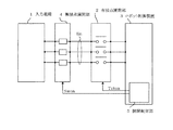
図1は、第1実施例を示すロボットシステムの入力電源投入遮断装置の構成図である。
図1において、1は入力電源、2はコンタクタなどの有接点開閉部、3はロボット制御装置、4はトランジスタ、サイリスタ等の半導体スイッチから成る無接点開閉部、5は開閉制御部である。また、Iinは有接点開閉部2に流れる流入電流、Swonは無接点開閉信号、Tctonは有接点開閉信号である。なお、図1では3相電源で表記しているが、相数は規定しない。
本発明の特徴は以下のとおりである。
すなわち、入力電源1と有接点開閉部2の間に配置され有接点開閉部2の接点と直列に電気接続された無接点開閉部4と、ロボット制御装置3の電源投入時には有接点開閉部2より無接点開閉部4が遅く閉じ、ロボット制御装置3の電源遮断時には有接点開閉部2より無接点開閉部4が早く開くように制御する開閉制御部5と、を備えるようにしている点である。
FIG. 1 is a configuration diagram of an input power-on / off device of a robot system showing a first embodiment.
In FIG. 1, 1 is an input power source, 2 is a contact opening / closing unit such as a contactor, 3 is a robot control device, 4 is a non-contact opening / closing unit composed of a semiconductor switch such as a transistor or thyristor, and 5 is an opening / closing control unit. Further, Iin is an inflow current flowing through the contact opening / closing unit 2, Swon is a contactless opening / closing signal, and Tcton is a contact opening / closing signal. In FIG. 1, a three-phase power supply is used, but the number of phases is not specified.
The features of the present invention are as follows.
That is, the contactless switching unit 4 disposed between the
図2は、本発明のロボットシステムの入力電源投入遮断装置の動作を示すシーケンス図である。図2において、横軸は時間を示し、縦軸は入力電源電圧Vin、無接点開閉信号Swon、有接点開閉信号Tcton、有接点開閉部2の接点の実際の開閉状態、有接点開閉部2に流れる流入電流Iinを示している。また、図2のtdは有接点開閉部2の機械的遅れ時間である。
以下、図1および図2を用いて本実施例における開閉制御部5の動作を説明する。
電源投入すなわち有接点開閉部2の接点を閉じる場合には、予め無接点開閉素子4を無接点開閉信号Swonにより開状態としておき、入力電源1から有接点開閉部2までの回路を遮断した状態にて、有接点開閉部2を有接点開閉信号Tctonにより閉状態とし、その後、有接点開閉部2の機械的遅れ時間td以上経った後、無接点開閉素子4を無接点開閉信号Swonにより閉状態にする。
一方、電源遮断すなわち接点を開く場合は、先に無接点開閉素子4を無接点開閉信号Swonにより開状態とし、その後、有接点開閉部2を有接点開閉信号Tctonにより開状態にする。
以上の動作により、有接点開閉部2の実際の開閉点である図2のA、Bの時点では、有接点開閉部2に流入する電流Iinを0とする事が出来る。
FIG. 2 is a sequence diagram showing the operation of the input power on / off device of the robot system of the present invention. In FIG. 2, the horizontal axis represents time, and the vertical axis represents the input power supply voltage Vin, the contactless switching signal Swon, the contact switching signal Tcton, the actual switching state of the contact of the contact switching unit 2, and the contact switching unit 2. A flowing inflow current Iin is shown. Further, td in FIG. 2 is a mechanical delay time of the contact opening / closing part 2.
Hereinafter, the operation of the opening / closing control unit 5 in this embodiment will be described with reference to FIGS. 1 and 2.
When the power is turned on, that is, when the contact of the contact switching unit 2 is closed, the contactless switching element 4 is opened in advance by the contactless switching signal Swon, and the circuit from the
On the other hand, when the power is shut off, that is, when the contact is opened, the contactless switching element 4 is first opened by the contactless switching signal Swon, and then the contact switching unit 2 is opened by the contact switching signal Tcton.
With the above operation, the current Iin flowing into the contact opening / closing unit 2 can be set to zero at the time points A and B in FIG.
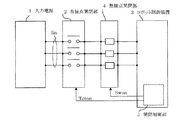
図3は、第2実施例を示すロボットシステムの入力電源投入遮断装置の構成図である。
図3において、図1と同じ説明符号のものは、図1と同じ構成要素および信号を示しているものとし、その説明は省略する。
本実施例が、第1実施例と相違する点は以下のとおりである。
すなわち、本実施例は、第1実施例である図1を構成する無接点開閉素子4を、入力電源1と有接点開閉部2の間の設置に代えて、有接点開閉部2とロボット制御装置3の間に設置する構成としたものであり、その他の構成は第1実施例と同じであり、動作シーケンスも第1実施例における図2と同じである。
以下、図2、3を用いて本実施例における開閉制御部5の動作を説明する。
電源投入すなわち接点を閉じる場合には、予め無接点開閉部4を無接点開閉信号Swonにより開状態としておき、有接点開閉部2を有接点開閉信号Tctonにより閉状態とし、その後、有接点開閉部2の機械的遅れ時間td以上経った後、無接点開閉部4を無接点開閉信号Swonにより閉状態にする。
電源遮断すなわち接点を開く場合は、先に無接点開閉部4を無接点開閉信号Swonにより開状態とし、その後、有接点開閉部2を有接点開閉信号Tctonにより開状態にする。
FIG. 3 is a block diagram of an input power on / off device of the robot system showing the second embodiment.
3, the same reference numerals as those in FIG. 1 indicate the same components and signals as those in FIG. 1, and the description thereof is omitted.
The difference between the present embodiment and the first embodiment is as follows.
That is, in the present embodiment, the contactless switching element 4 constituting the first embodiment shown in FIG. 1 is replaced with the contacted switching unit 2 and the robot control instead of the installation between the
Hereinafter, the operation of the opening / closing controller 5 in this embodiment will be described with reference to FIGS.
When the power is turned on, that is, when the contact is closed, the contactless switching unit 4 is opened in advance by the contactless switching signal Swon, the contacted switching unit 2 is closed by the contacted switching signal Tcton, and then the contacted switching unit After two mechanical delay times td have elapsed, the contactless switching unit 4 is closed by a contactless switching signal Swon.
When the power is shut off, that is, when the contact is opened, the contactless switching unit 4 is first opened by the contactless switching signal Swon, and then the contact switching unit 2 is opened by the contact switching signal Tcton.
以上述べたように、本発明の第1、2実施例に係るロボットシステムの入力電源投入遮断装置は、入力電源1と有接点開閉部2の間、またはロボット制御装置3と有接点開閉部2の間に設置され、有接点開閉部2の接点と直列に電気接続された半導体スイッチなどの無接点開閉部4を備え、無接点開閉部4は、投入時には有接点開閉部2より遅く閉じられ、遮断時には有接点開閉部2より早く開かれる有接点開閉部2の開閉前に通電を停止する開閉制御部5を備える構成としているので、非常の際の回路切断不良や、通常稼働時の熱ロスの発生を抑制できるとともに、有接点開閉部2の接点は無通電開閉であるため、有接点開閉部2の劣化を無くし有接点開閉部2の寿命を飛躍的に延長することができるため、メンテナンス期間を長期化、もしくはメンテナンスフリーにすることができる。
As described above, the input power on / off device of the robot system according to the first and second embodiments of the present invention is between the
通電開閉を行う有接点開閉部を有し、メンテナンス期間の長期化もしくはメンテナンスフリーが求められるシステムの入力電源投入遮断装置への適用が可能である。 It has a contact opening / closing part that performs energization switching, and can be applied to an input power on / off device of a system that requires a longer maintenance period or maintenance-free.
1 入力電源
2 コンタクタなどの有接点開閉部
3 ロボット制御装置
4 トランジスタ、サイリスタ等の半導体スイッチから成る無接点開閉部
5 開閉制御部
DESCRIPTION OF
Claims (3)
前記入力電源(1)と前記有接点開閉部(2)の間に配置され前記有接点開閉部(2)の接点と直列に電気接続された無接点開閉部(4)と、
前記ロボット制御装置(3)の電源投入時には前記有接点開閉部(2)より前記無接点開閉部(4)が遅く閉じ、前記ロボット制御装置(3)の電源遮断時には前記有接点開閉部(2)より前記無接点開閉部(4)が早く開くように制御する開閉制御部(5)と、を備えたことを特徴とするロボットシステムの入力電源投入遮断装置。 In the input power on / off device of the robot system, which is provided between the input power source (1) and the robot control device (3) and has a contact switching unit (2) that mechanically opens and closes the circuit,
A contactless switching part (4) disposed between the input power source (1) and the contacted switching part (2) and electrically connected in series with the contact of the contacted switching part (2);
The contactless switching unit (4) closes later than the contacted switching unit (2) when the robot controller (3) is turned on, and the contacted switching unit (2) when the robot controller (3) is powered off. And an open / close control unit (5) for controlling the non-contact open / close unit (4) to open earlier.
前記ロボット制御装置(3)と前記有接点開閉部(2)の間に配置され、前記有接点開閉部(2)の接点と直列に電気接続された無接点開閉部(4)と、
前記ロボット制御装置(3)の電源投入時には前記有接点開閉部(2)より前記無接点開閉部(4)が遅く閉じ、前記ロボット制御装置(3)の電源遮断時には前記有接点開閉部(2)より前記無接点開閉部(4)が早く開くように制御する開閉制御部(5)と、を備えたことを特徴とするロボットシステムの入力電源投入遮断装置。 In the input power on / off device of the robot system, which is provided between the input power source (1) and the robot control device (3) and has a contact switching unit (2) that mechanically opens and closes the circuit,
A contactless switching unit (4) disposed between the robot control device (3) and the contacted switching unit (2) and electrically connected in series with a contact of the contacted switching unit (2);
The contactless switching unit (4) closes later than the contacted switching unit (2) when the robot controller (3) is turned on, and the contacted switching unit (2) when the robot controller (3) is powered off. And an open / close control unit (5) for controlling the non-contact open / close unit (4) to open earlier.
半導体スイッチであることを特徴とする請求項1または2に記載のロボットシステムの入力電源投入遮断装置。 The non-contact opening / closing part (4)
3. The input power-on / off device for a robot system according to claim 1, wherein the device is a semiconductor switch.
Priority Applications (1)
| Application Number | Priority Date | Filing Date | Title |
|---|---|---|---|
| JP2005303188A JP2007116777A (en) | 2005-10-18 | 2005-10-18 | Device for breaking input of power supply input of robot system |
Applications Claiming Priority (1)
| Application Number | Priority Date | Filing Date | Title |
|---|---|---|---|
| JP2005303188A JP2007116777A (en) | 2005-10-18 | 2005-10-18 | Device for breaking input of power supply input of robot system |
Publications (1)
| Publication Number | Publication Date |
|---|---|
| JP2007116777A true JP2007116777A (en) | 2007-05-10 |
Family
ID=38098455
Family Applications (1)
| Application Number | Title | Priority Date | Filing Date |
|---|---|---|---|
| JP2005303188A Pending JP2007116777A (en) | 2005-10-18 | 2005-10-18 | Device for breaking input of power supply input of robot system |
Country Status (1)
| Country | Link |
|---|---|
| JP (1) | JP2007116777A (en) |
Cited By (2)
| Publication number | Priority date | Publication date | Assignee | Title |
|---|---|---|---|---|
| JP2009012946A (en) * | 2007-07-05 | 2009-01-22 | Mitsubishi Electric Corp | Driving circuit of brake coil |
| KR20170133739A (en) * | 2016-05-26 | 2017-12-06 | 현대일렉트릭앤에너지시스템(주) | Switchboard |
-
2005
- 2005-10-18 JP JP2005303188A patent/JP2007116777A/en active Pending
Cited By (3)
| Publication number | Priority date | Publication date | Assignee | Title |
|---|---|---|---|---|
| JP2009012946A (en) * | 2007-07-05 | 2009-01-22 | Mitsubishi Electric Corp | Driving circuit of brake coil |
| KR20170133739A (en) * | 2016-05-26 | 2017-12-06 | 현대일렉트릭앤에너지시스템(주) | Switchboard |
| KR102150429B1 (en) * | 2016-05-26 | 2020-09-01 | 현대일렉트릭앤에너지시스템(주) | Switchboard |
Similar Documents
| Publication | Publication Date | Title |
|---|---|---|
| JP2005158749A (en) | Method and apparatus for independently controlling contactor in multiple contactor configuration | |
| EP3443629B1 (en) | Paralleling mechanical relays for increased current carrying and switching capacity | |
| JP2009059662A (en) | Power switching apparatus and method for controlling it | |
| JP2013214406A (en) | Circuit cut-off switch for dc circuit | |
| US6611416B1 (en) | Safety relay circuit for large power contactors | |
| JPWO2008132975A1 (en) | Power converter | |
| JP6202871B2 (en) | DC circuit breaker | |
| KR20150142546A (en) | Electromagnetic contactor and control method thereof | |
| JP4955363B2 (en) | Inverter device | |
| JP2007116777A (en) | Device for breaking input of power supply input of robot system | |
| EP2407993B1 (en) | An improved trip circuit supervision relay for low and medium voltage applications | |
| JP6120723B2 (en) | Control circuit, control circuit short circuit fault detection method, switch control circuit short circuit fault detection method, and railway signal interlock control system | |
| JP2015118868A (en) | DC switch | |
| JP2000215772A (en) | Interlock circuit | |
| JP2007035388A (en) | Power supply device of automatic machine | |
| JP4799371B2 (en) | Circuit breaker status monitoring device | |
| JP2009177958A (en) | Switchgear with exciting rush current suppressor | |
| KR100888775B1 (en) | The power controlling apparatus and method of heating device and lamp | |
| WO2021054338A1 (en) | Current interruption device and current interruption method | |
| WO2023242989A1 (en) | Shut-off control device | |
| JP4839725B2 (en) | Electronic switch | |
| CN113659915A (en) | Motor, motor pre-protection control method and pre-protection system | |
| JP2004031322A (en) | Method for switching breaker, and apparatus for carrying out the method in system-synchronous manner | |
| JP4592365B2 (en) | Vacuum shut-off device control circuit | |
| KR200267052Y1 (en) | relay protection circuit using photo sensor |