JP2007111929A - Heating unit of printer device - Google Patents
Heating unit of printer device Download PDFInfo
- Publication number
- JP2007111929A JP2007111929A JP2005303828A JP2005303828A JP2007111929A JP 2007111929 A JP2007111929 A JP 2007111929A JP 2005303828 A JP2005303828 A JP 2005303828A JP 2005303828 A JP2005303828 A JP 2005303828A JP 2007111929 A JP2007111929 A JP 2007111929A
- Authority
- JP
- Japan
- Prior art keywords
- heating unit
- tube
- printing
- heating
- shaped substrate
- Prior art date
- Legal status (The legal status is an assumption and is not a legal conclusion. Google has not performed a legal analysis and makes no representation as to the accuracy of the status listed.)
- Pending
Links
Images


Abstract
Description
本発明は、チューブ状被印字物に文字や記号等を印字するプリンタ装置に着脱自在な加熱ユニットに関する。 The present invention relates to a heating unit that is detachable from a printer device that prints characters, symbols, and the like on a tube-shaped substrate.
従来のこの種のプリンタ装置では、チューブ状被印字物に印字する際に、印字ヘッドとプラテンローラとでチューブ状被印字物を強く挟み、チューブ状被印字物を押しつぶすように変形させて印字を行っている。 In a conventional printer of this type, when printing on a tube-shaped substrate, the tube-shaped substrate is strongly sandwiched between the print head and the platen roller, and the tube-shaped substrate is deformed so as to be crushed. Is going.
一方、外気温が低下しチューブ状被印字物が冷たくなるとチューブ状被印字物が硬くなり、変形しにくくなる。チューブ状被印字物が十分に変形しないとチューブ状被印字物の表面が印字ヘッドに当接せず、そのため正常に印字することができない。 On the other hand, when the outside air temperature decreases and the tube-shaped printed material becomes cold, the tube-shaped printed material becomes hard and is not easily deformed. If the tube-shaped printed material is not sufficiently deformed, the surface of the tube-shaped printed material does not come into contact with the print head, so that normal printing cannot be performed.
このような不具合を解消するため、プリンタ装置の印字機構の上流側にチューブ状被印字物を加熱する着脱自在の加熱ユニットを取り付け、チューブ状被印字物が印字ヘッドに供給される前にチューブ状被印字物を加熱し暖めて、チューブ状被印字物が柔らかくなるようにしている。
上記加熱ユニットを用いてチューブ状被印字物は加熱されるが、プリンタ装置と通信していない為、プリンタ装置が動作していない場合も加熱ユニットは電源スイッチを入れておけば温調が始まり完了する間、加熱ユニットにチューブ状被印字物をセットしていると必要以上にチューブ状被印字物は加熱され柔らかくなり、その状態でプリンタ装置を動作して印刷を開始すると柔らかくなり過ぎたチューブ状被印字物はプリンタ装置内の搬送路で搬送不良を起こす問題があった。 The tube-shaped substrate is heated using the heating unit, but because it is not communicating with the printer device, the heating unit starts and finishes temperature control if the power unit is turned on even when the printer device is not operating. During this process, if the tube-shaped substrate is set in the heating unit, the tube-shaped substrate will be heated and become softer than necessary. There is a problem that the printed material causes a conveyance failure in the conveyance path in the printer apparatus.
通常プリンタ装置に着脱自在な加熱ユニットは、ヒーターの温度調節完了後チューブ状被印字物を加熱ユニットにセットして印刷を開始する。 Usually, the heating unit that is detachable from the printer device starts printing by setting the tube-shaped substrate to the heating unit after the temperature adjustment of the heater is completed.
また、プリンタ本体と加熱ユニットを通信ケーブル等で加熱ユニットの制御を行う場合はプリンタ本体のコストアップとなる為、加熱ユニットを使用しないユーザーにとっては不必要なプリンタ装置の構成になってしまう。 Further, when the heating unit is controlled between the printer main body and the heating unit using a communication cable or the like, the cost of the printer main body is increased, so that the configuration of the printer device is unnecessary for a user who does not use the heating unit.
上記課題を解決するために本発明は、被印字物に印字を行う印字機構を備えたプリンタ装置に、加熱する加熱手段を設けた加熱ユニットに於いて、前記加熱ユニットに被印刷物の有無を検知する有無検知機構を備えた事を特徴とするプリンタ装置。 In order to solve the above-mentioned problems, the present invention detects a presence or absence of a printing material in a heating unit provided with a heating means for heating in a printer device having a printing mechanism for printing on the printing material. A printer device characterized by having a presence / absence detecting mechanism.
また、前記加熱ユニットには被印刷物の搬送を検知する搬送検知機構を備えた事を特徴とするプリンタ装置。 The printer device is characterized in that the heating unit is provided with a conveyance detection mechanism for detecting conveyance of the substrate.
また、前記加熱ユニットは着脱可能であることを特徴とするプリンタ装置。 The printer apparatus is characterized in that the heating unit is detachable.
また、前記加熱手段は被印刷物の搬送の検知に応じて、温度調節が行われることを特徴とするプリンタ装置。 The printer is characterized in that the heating means adjusts the temperature in response to detection of conveyance of the substrate.
また、前記加熱手段の温度調節が停止した場合、被印刷物を前記加熱ユニットから取り出さないと加熱手段が作動しないことを特徴とする加熱ユニット。 Further, the heating unit is characterized in that when the temperature adjustment of the heating means is stopped, the heating means does not operate unless the substrate is taken out of the heating unit.
また、被印刷物が加熱ユニットにセットされても、所定時間印字開始が行われない場合は、前記加熱手段が作動しないことを特徴とする加熱ユニット。 In addition, the heating unit does not operate when printing is not started for a predetermined time even if the substrate is set in the heating unit.
以上説明から明らかな様に、本発明はチューブ状被印字物に印字を行う印字機構を備えたプリンタ装置に、着脱自在に加熱する加熱手段を設けた加熱ユニットに於いて、加熱ユニットにチューブ状被印刷物の有無検知機構及び搬送検知機構を備えた事で、長時間印刷動作を行わない状態で加熱ユニット内にチューブ状被印字物を放置しても、必要以上の加熱でチューブ状被印字物を柔らかくしないので、コシの弱くなったチューブ状被印字物が、プリンタ装置の搬送路で搬送不良となる問題を防止する事ができる。 As is apparent from the above description, the present invention provides a heating unit in which a heating mechanism for detachably heating is provided in a printer device provided with a printing mechanism for printing on a tubular printed material. By providing the presence / absence detection mechanism and conveyance detection mechanism of the substrate, even if the tube-shaped substrate is left in the heating unit without performing a printing operation for a long time, the tube-shaped substrate can be heated by heating more than necessary. Therefore, it is possible to prevent the problem that the tube-like printed material having weakness becomes poor in the conveyance path of the printer device.
さらに、加熱ユニットに本発明の構成を盛り込む事で、プリンタ装置への変更が無くコストアップを防ぎ、気温の高い場所で加熱ユニットを使用しないでプリンタ装置を使用するユーザーにプリンタ装置を安価で提供する事もできる。 In addition, by incorporating the configuration of the present invention in the heating unit, there is no change to the printer device, preventing an increase in cost, and providing the printer device at a low price to users who use the printer device without using the heating unit in places with high temperatures. You can also do it.
以下に、本発明に係わる実施形態を図面で詳細に説明する。 Embodiments according to the present invention will be described below in detail with reference to the drawings.
図1を参照して、1は本発明にかかわるプリンタ装置であり、上面に設けたセット位置2にカセット4と加熱ユニット3とのうちのいずれか一方が着脱自在にセットされる。カセット4にはテープ状被印字物TPがロール状に巻回された状態で格納されている。このカセット4をセット位置2にセットすると、1対の搬送ローラ5によってテープ状被印字物TPが挟まれ一定の速度で印字ヘッド6に送られる。
Referring to FIG. 1, reference numeral 1 denotes a printer apparatus according to the present invention, and either one of a cassette 4 and a
印字ヘッド6に対向するプラテンローラ7と印字ヘッド6とでテープ状被印字物TPに印字を行う。
Printing is performed on the tape-shaped printing material TP by the
一方、直径50cm程度のロール状に巻回されているリールからチューブ状被印字物Tを引き出して印字を行う際には、加熱ユニット3をセット位置2にセットし、チューブ状被印字物Tの一端を引き出して加熱ユニット3に通して搬送ローラ5に挟まれるようにした。なお、8は温度センサーであり、外気温を検知して印字ヘッド6が印加する熱量を気温に応じて変更するようにした。
On the other hand, when printing is performed by pulling out the tube-shaped substrate T from a reel wound in a roll shape having a diameter of about 50 cm, the
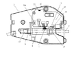
図2を参照して、加熱ユニット3内には加熱手段であるパイプ状のヒーター9が設けられている。チューブ状被印字物Tを加熱ユニット3に通すと、このヒーター9内をチューブ状被印字物Tが通ることになる。
Referring to FIG. 2, a pipe-
気温が高いためチューブ状被印字物Tが柔らかく印字が良好に行われている状態ではスイッチ10はOFFにする。スイッチ10がOFFであるとヒーター9に通電されず、従ってチューブ状被印字物Tが加熱されることはない。
The
ところで、チューブ状以外の長尺被印字物がリールに巻かれている場合に、その長尺被印字物に印字する際にはこのような加熱ユニット3と同様の構成の加熱ユニットを用いればよい。ただし、長尺被印字物用の加熱ユニットにはヒーター9を内蔵させる必要はない。
By the way, when a long printed material other than a tube is wound on a reel, a heating unit having the same configuration as the
気温が低下しチューブ状被印字物Tが冷えて硬くなり、印字が良好に行われなくなると、スイッチ10をONにする。
When the temperature drops and the tube-shaped substrate T is cooled and hardened, and printing cannot be performed satisfactorily, the
このスイッチ10は外気温に応じて加熱温度を2段階に切り換えることができるように、低温で加熱する「L」と高温で加熱する「H」との2カ所を選択できるようになっている。
The
すなわち、外気温が非常に低温であり、チューブ状被印字物Tがとても硬くなっている場合にはスイッチ10を「H」にして高温で加熱し、外気温がそれほど低温でない場合にはスイッチ10を「L」にして低温で加熱する。
That is, when the outside air temperature is very low and the tube-shaped substrate T is very hard, the
また、外気温の高低だけではなく、チューブ状被印字物Tの材質や厚み等の諸条件により、加熱されやすく、あるいは伸びやすい場合にはスイッチ10を「L」にし、逆の場合にはスイッチ10を「H」に切り換える。
In addition, the
「L」が選択されると略60℃でチューブ状被印字物Tが加熱され、「H」が選択されると略80℃でチューブ状被印字物Tが加熱されるように設定されている。なお、11はサーミスタであり、ヒーター9の温度を検知するものであり、その検知温度に基づいてヒーター9への通電状態が制御される。
When “L” is selected, the tube-shaped substrate T is heated at approximately 60 ° C., and when “H” is selected, the tube-shaped substrate T is heated at approximately 80 ° C. .
また、12は発光ダイオードであり、通電状態に応じて「点灯」「点滅」「消灯」のいずれかの状態になる。
なお、本実施の形態では加熱温度を「L」「H」の2段階に切り換えるように構成したが、設定温度を連続して変更できるようにしてもよい。 In this embodiment, the heating temperature is switched to two stages of “L” and “H”, but the set temperature may be changed continuously.
また、本実施の形態では、発光ダイオード12が「点灯」の状態になったら、図3に示す様にチューブ状被印字物Tを加熱ユニット3に装着すると、媒体押え13が動作して加熱ユニット3の基板16上のセンサー14Aでチューブ状被印字物Tを検知する。
Further, in the present embodiment, when the
これは、チューブ状被印字物Tを検知約30秒後にプリンタ装置1側で印字動作が無い場合はヒーター9への通電を停止させ発光ダイオード12を「消灯」させる。これはチューブ状被印字物Tの必要以上の加熱を中断させる為である。
This means that when there is no printing operation on the printer device 1 side after about 30 seconds after detecting the tube-shaped substrate T, the power supply to the
この場合、図4に示す様に一度チューブ状被印字物Tを加熱ユニット3から取り出すと、押えバネ15で媒体押え13が戻り基板16上のセンサー14Aを切らないのでチューブ状被印字物Tが「無」になる。その後スイッチ10のOFF/ON(L)(H)を行う事で発光ダイオード12は「点滅」して再度ヒーター9の温度調節が開始する。
In this case, as shown in FIG. 4, once the tubular printed matter T is taken out of the
この時、チューブ状被印字物Tを加熱ユニット3にセットしたままスイッチ10をOFF/ON(L)(H)しても有無検知機構であるセンサー14Aが「有」になっている為、ヒーター9への通電は行われないので、この制御手段に於いてもチューブ状被印字物Tの必要以上の加熱を防いでいる。
At this time, even if the
尚、チューブ状被印字物Tを加熱ユニット3にセット後30秒以内に印刷動作が行えている場合は、搬送検知機構であるエンコーダ17付きの検知ローラ18がチューブ状被印字物Tの搬送により回転して基板16上のセンサー14Bでチューブ状被印字物Tの搬送を検知するのでヒーター9は温度調節を続ける。
In addition, when the printing operation can be performed within 30 seconds after the tube-shaped substrate T is set in the
図3、4に示すように、加熱ユニット3にはヒーター9で加熱されたチューブ状被印字物Tが印字ヘッド6に到達されるまでの間、チューブ状被印字物Tを覆う庇部19が設けられている。
As shown in FIGS. 3 and 4, the
このように庇部19でチューブ状被印字物Tを覆うことにより、ヒーター9で加熱されたチューブ状被印字物Tが印字ヘッド6に到達するまでの間に冷却されることを防止できる。
By covering the tube-shaped substrate T with the
また、庇部19は冷却防止の他にも、ヒーター9と媒体押え13と押えバネ15と検知ローラ18を押える構成にもなっている。
In addition to preventing cooling, the
ところで、本実施の形態では、スイッチ10がOFFの状態であれば発光ダイオード12は「消灯」しており、スイッチ10を「L」または「H」にした状態であって、サーミスタ11で検知される温度が予め設定した範囲にない場合には「点滅」し、その検知温度が所定範囲内にある場合には印字可能であるとして「点灯」するようにした。
By the way, in the present embodiment, if the
具体的には、図5を参照して、まずスイッチ10を「L」にするとヒーター9への通電が開始され、発光ダイオード12は「点滅」する。スイッチ10が「L」の場合の下限温度である55℃を超えると印字可能であるとして発光ダイオード12を「点滅」から「点灯」に切り換えるようにした。
Specifically, referring to FIG. 5, when
「L」の上限温度である65℃を超えるとヒーター9への通電を停止する。するとヒーター9の温度は低下し、再び下限温度である55℃以下になるまで発光ダイオード12を「点灯」し続ける。
When it exceeds 65 ° C, which is the upper limit temperature of “L”, energization to the
次に、スイッチ10が「H」に切り換えられると、検知温度が55℃から65℃の間に入っていても、発光ダイオード12を「点滅」に切り換え、ヒーター9への通電を再開する。スイッチ10が「H」にされた状態での下限温度は75℃であり上限温度は83℃に設定した。
Next, when the
検知温度が75℃から83℃の間にあり発光ダイオード12が「点灯」している状態で再びスイッチ10が「L」に切り換えられると、ヒーター9への通電を停止させると共に検知温度が65℃以下になるまで発光ダイオード12を「点滅」させる。そして、スイッチ10が図1に示すOFF状態に戻されるとヒーター9への通電を停止し、かつ発光ダイオード12を「消灯」させるようにした。
If the
但し、スイッチ10を「L」または「H」にした状態であっても加熱ユニット3にチューブ状被印字物Tをセットから約30秒後に印刷動作が無い場合と、加熱ユニット3にチューブ状被印字物Tをセットした状態でのスイッチ10を「L」または「H」にした場合には、発光ダイオード12は「消灯」する。
However, even when the
従って、作業者は発光ダイオード12の「点灯」状態を確認し、「点滅」状態から「点灯」状態に切り替わると印字可能であると判断して、加熱ユニット3にチューブ状被印字物Tをセットし印字作業を開始する。
Accordingly, the operator checks the “lighting” state of the light-emitting
図6はチューブ状被印字媒体Tに印字する時の加熱ユニットのフローチャートを示している。 FIG. 6 shows a flowchart of the heating unit when printing on the tube-shaped print medium T.
1 プリンタ装置
2 セット位置
3 加熱ユニット
4 カセット
5 搬送ローラ
6 印字ヘッド
7 プラテンローラ
8 温度センサー
9 ヒーター
10 スイッチ
11 サーミスタ
12 発光ダイオード
13 媒体押え
14A センサー
14B センサー
15 押えバネ
16 基板
17 エンコーダ
18 検知ローラ
19 庇部
T チューブ状被印字媒体
1 Printer device
2 Set position
3 Heating unit
4 cassettes
5 Transport roller
6 Print head
7 Platen roller
8 Temperature sensor
9 Heater
10 switch
11 Thermistor
12 Light emitting diode
13 Media presser
14A sensor
14B sensor
15 Presser spring
16 substrate
17 Encoder
18 Detection roller
19 Buttocks T Tube-shaped printing medium
Claims (6)
6. The heating unit according to claim 1, wherein the heating unit does not operate when printing is not started for a predetermined time even if the substrate is set in the heating unit.
Priority Applications (1)
| Application Number | Priority Date | Filing Date | Title |
|---|---|---|---|
| JP2005303828A JP2007111929A (en) | 2005-10-19 | 2005-10-19 | Heating unit of printer device |
Applications Claiming Priority (1)
| Application Number | Priority Date | Filing Date | Title |
|---|---|---|---|
| JP2005303828A JP2007111929A (en) | 2005-10-19 | 2005-10-19 | Heating unit of printer device |
Publications (2)
| Publication Number | Publication Date |
|---|---|
| JP2007111929A true JP2007111929A (en) | 2007-05-10 |
| JP2007111929A5 JP2007111929A5 (en) | 2008-10-30 |
Family
ID=38094559
Family Applications (1)
| Application Number | Title | Priority Date | Filing Date |
|---|---|---|---|
| JP2005303828A Pending JP2007111929A (en) | 2005-10-19 | 2005-10-19 | Heating unit of printer device |
Country Status (1)
| Country | Link |
|---|---|
| JP (1) | JP2007111929A (en) |
Cited By (3)
| Publication number | Priority date | Publication date | Assignee | Title |
|---|---|---|---|---|
| JP2011218733A (en) * | 2010-04-13 | 2011-11-04 | Max Co Ltd | Tube printer |
| US20210252875A1 (en) * | 2020-02-14 | 2021-08-19 | Canon Finetech Nisca Inc. | Printing apparatus |
| JP2021126902A (en) * | 2020-02-14 | 2021-09-02 | キヤノンファインテックニスカ株式会社 | Recording device |
Citations (3)
| Publication number | Priority date | Publication date | Assignee | Title |
|---|---|---|---|---|
| JPH06171794A (en) * | 1992-12-11 | 1994-06-21 | Casio Electron Mfg Co Ltd | Image forming device |
| JP2003103844A (en) * | 2001-10-02 | 2003-04-09 | Canon Ntc Inc | Printer unit and heating unit |
| JP2004233823A (en) * | 2003-01-31 | 2004-08-19 | Canon Inc | Image forming apparatus |
-
2005
- 2005-10-19 JP JP2005303828A patent/JP2007111929A/en active Pending
Patent Citations (3)
| Publication number | Priority date | Publication date | Assignee | Title |
|---|---|---|---|---|
| JPH06171794A (en) * | 1992-12-11 | 1994-06-21 | Casio Electron Mfg Co Ltd | Image forming device |
| JP2003103844A (en) * | 2001-10-02 | 2003-04-09 | Canon Ntc Inc | Printer unit and heating unit |
| JP2004233823A (en) * | 2003-01-31 | 2004-08-19 | Canon Inc | Image forming apparatus |
Cited By (4)
| Publication number | Priority date | Publication date | Assignee | Title |
|---|---|---|---|---|
| JP2011218733A (en) * | 2010-04-13 | 2011-11-04 | Max Co Ltd | Tube printer |
| US20210252875A1 (en) * | 2020-02-14 | 2021-08-19 | Canon Finetech Nisca Inc. | Printing apparatus |
| JP2021126902A (en) * | 2020-02-14 | 2021-09-02 | キヤノンファインテックニスカ株式会社 | Recording device |
| JP7219293B2 (en) | 2020-02-14 | 2023-02-07 | キヤノンファインテックニスカ株式会社 | recording device |
Similar Documents
| Publication | Publication Date | Title |
|---|---|---|
| JP5398675B2 (en) | How to keep the temperature and size of the medium uniform throughout the preheating zone | |
| JP2007264318A (en) | Fixing device and image forming apparatus including the same | |
| EP1300733A3 (en) | Image forming apparatus and fixing apparatus including a power supply for heating at a fixing temperature when needed | |
| JP2007111929A (en) | Heating unit of printer device | |
| JP4070441B2 (en) | Printer device and heating unit | |
| JP2009107305A (en) | Printer and peeling method thereof | |
| JP2005313410A (en) | Long medium printer | |
| JP2004345253A (en) | Printer | |
| JP2008292860A (en) | Image forming device | |
| JP2006007561A (en) | Printer | |
| JP2005125796A (en) | Printer | |
| JP2007044933A (en) | Printer | |
| JP6901861B2 (en) | Label issuing device and its control method | |
| JP4111307B2 (en) | Fixing device | |
| JP2007185793A (en) | Printer | |
| JP2005349744A (en) | Printer | |
| JP2022157977A (en) | Foil transfer device | |
| JP2003341113A (en) | Thermal printer | |
| JP2001121768A (en) | Thermal transfer recording apparatus | |
| JP2021126891A (en) | Printing device | |
| JPH02217269A (en) | Thermal transfer recording device | |
| JP2002337375A (en) | Printer | |
| JP5901274B2 (en) | Printing apparatus and control method thereof | |
| JP2021066097A (en) | Printing apparatus | |
| JPS6315920B2 (en) |
Legal Events
| Date | Code | Title | Description |
|---|---|---|---|
| A521 | Written amendment |
Effective date: 20080910 Free format text: JAPANESE INTERMEDIATE CODE: A523 |
|
| A621 | Written request for application examination |
Free format text: JAPANESE INTERMEDIATE CODE: A621 Effective date: 20080910 |
|
| A711 | Notification of change in applicant |
Effective date: 20090122 Free format text: JAPANESE INTERMEDIATE CODE: A711 |
|
| A131 | Notification of reasons for refusal |
Effective date: 20110526 Free format text: JAPANESE INTERMEDIATE CODE: A131 |
|
| A02 | Decision of refusal |
Effective date: 20111007 Free format text: JAPANESE INTERMEDIATE CODE: A02 |