JP2007111144A - Toy top - Google Patents
Toy top Download PDFInfo
- Publication number
- JP2007111144A JP2007111144A JP2005303799A JP2005303799A JP2007111144A JP 2007111144 A JP2007111144 A JP 2007111144A JP 2005303799 A JP2005303799 A JP 2005303799A JP 2005303799 A JP2005303799 A JP 2005303799A JP 2007111144 A JP2007111144 A JP 2007111144A
- Authority
- JP
- Japan
- Prior art keywords
- shaft
- rotary
- shape
- top toy
- toy
- Prior art date
- Legal status (The legal status is an assumption and is not a legal conclusion. Google has not performed a legal analysis and makes no representation as to the accuracy of the status listed.)
- Pending
Links
Images


Classifications
-
- A—HUMAN NECESSITIES
- A63—SPORTS; GAMES; AMUSEMENTS
- A63H—TOYS, e.g. TOPS, DOLLS, HOOPS OR BUILDING BLOCKS
- A63H1/00—Tops
- A63H1/02—Tops with detachable winding devices
- A63H1/04—Tops with detachable winding devices with string or band winding devices
-
- A—HUMAN NECESSITIES
- A63—SPORTS; GAMES; AMUSEMENTS
- A63H—TOYS, e.g. TOPS, DOLLS, HOOPS OR BUILDING BLOCKS
- A63H1/00—Tops
- A63H1/20—Tops with figure-like features; with movable objects, especially figures
Landscapes
- Toys (AREA)
Abstract
Description
本発明は、コマ玩具に関するものである。 The present invention relates to a top toy.
従来、コマには様々な種類があり、例えば、コマの形状を円錐状に形成した「べーごま」と、心棒に胴輪を軸止させた「胴輪ごま」が一般的である。近年、このコマの上方に形象体を設け、互いのコマ同士を衝突させて遊ぶコマ玩具が知られている。 Conventionally, there are various types of tops, for example, “Basame Sesame” in which the shape of the top is formed in a conical shape, and “Borse Sesame” in which a trunk is fixed to a mandrel. In recent years, there has been known a top toy that is provided with a figure above the top and plays by colliding each other.
例えば、特開平9−38337号公報「遊戯装置」の如く、コマ本体と、コマ本体と一体に回転し且つ弾性部材により付勢される飛び出し部材で構成され、このコマ玩具同士を衝突させ、飛び出し部材が飛び出した方が負けとなるコマ玩具がある。このコマ玩具のように、従来のコマ玩具におけるコマ本体と飛び出し部材は、コマ本体が回転すると、飛び出し部材も同様に回転するものであり、回転中の飛び出し部材は、その形状を視認できるものではなかった。 For example, as disclosed in Japanese Patent Application Laid-Open No. 9-38337, “game device”, it is composed of a top body and a pop-out member that rotates integrally with the top body and is urged by an elastic member. There is a top toy that loses when the member jumps out. Like this top toy, the top main body and the pop-out member in the conventional top toy are such that when the top main body rotates, the pop-out member rotates in the same way, and the rotating pop-out member cannot visually recognize its shape. There wasn't.
そこで、コマ本体が回転しても、コマの上方に配置した形象体が、コマ本体の回転の影響を受け難くしたコマ玩具が求められていた。
そこで、本発明は、上記従来技術の問題点に斯かる実情に鑑みなされたもので、コマ本体が回転しても、コマ本体の上方に配置した保持部を有する形象体が、コマ本体からの回転の影響を受け難くくし、コマ本体が回転中に形象体を視認しやすくするコマ玩具を提供することを課題とする。 Accordingly, the present invention has been made in view of the above-described problems of the prior art, and even if the frame main body rotates, a figure having a holding portion disposed above the frame main body is removed from the frame main body. It is an object of the present invention to provide a top toy that is less affected by rotation and that makes it easy to visually recognize a figure while the top body is rotating.
請求項1記載の発明は、回転コマ軸と前記回転コマ軸に軸止したフライホイール部と形象体とからなるコマ玩具であって、形象体の内部にピボット受け部が形成され、前記回転コマ軸の上方先端は、錐形状とされ、前記回転コマ軸の上方先端で前記ピボット受け部を点接点支持することによって前記形象体を前記フライホイール部の上方に支持し、前記回転コマ軸とピボット受け部との回転抵抗を小さくていることを特徴とする。 The invention according to claim 1 is a top toy comprising a rotary piece shaft, a flywheel portion fixed to the rotary piece shaft, and a figure, wherein a pivot receiving part is formed inside the figure, and the rotary piece An upper tip of the shaft is formed in a conical shape, and the shape receiving body is supported above the flywheel portion by supporting the pivot receiving portion at a point contact with the upper tip of the rotary piece shaft, and the pivot piece and the pivot are pivoted. The rotational resistance with the receiving portion is small.
請求項2記載の発明は、請求項1において、前記ピボット受け部は、前記形象体の重心位置近傍の上方に配設されていることを特徴とする。 According to a second aspect of the present invention, in the first aspect, the pivot receiving portion is disposed above the vicinity of the center of gravity of the figure.
請求項3記載の発明は、請求項1又は2において、前記フライホイール部に外嵌するリング体を有し、前記リング体の外周面には、所定の間隔に凸部が形成されていることを特徴とする。 Invention of Claim 3 has the ring body externally fitted to the said flywheel part in Claim 1 or 2, and the convex part is formed in the outer peripheral surface of the said ring body in the predetermined space | interval. It is characterized by.
請求項4記載の発明は、請求項3において、前記形象体の幅がリング体の外径より小さく、リング体が形象体の側方に突出していることを特徴とする。 The invention described in claim 4 is characterized in that, in claim 3, the width of the figure is smaller than the outer diameter of the ring, and the ring protrudes to the side of the figure.
請求項5記載の発明は、請求項1乃至4のいずれか1項において、前記回転コマ軸の下方先端を嵌入するコマ軸カバーを有し、前記コマ軸カバーの下端は、略半球形状に形成されていることを特徴とする。 According to a fifth aspect of the present invention, in any one of the first to fourth aspects, the frame includes a top shaft cover that fits a lower tip of the rotary top shaft, and a lower end of the top shaft cover is formed in a substantially hemispherical shape. It is characterized by being.
請求項6記載の発明は、請求項1乃至5のいずれか1項において、前記回転コマ軸に軸止されたピニオンギアを有し、前記形象体の内部に前記ピニオンギアと歯合するラックベルトを挿入するためのラックベルト挿入路が形成されていることを特徴とする。 A sixth aspect of the present invention is the rack belt according to any one of the first to fifth aspects, wherein the rack belt has a pinion gear fixed to the rotary piece shaft and meshes with the pinion gear inside the figure. A rack belt insertion path for inserting the rack is formed.
請求項7記載の発明は、請求項1乃至6のいずれか1項において、前記回転コマ軸は、回転コマ軸に軸止された脱落防止具を有し、前記回転コマ軸の前記形象体からの脱落が防止されていることを特徴とする。 A seventh aspect of the present invention provides the rotary piece shaft according to any one of the first to sixth aspects, wherein the rotary piece shaft includes a drop-off preventing tool fixed to the rotary piece shaft, It is characterized in that it is prevented from falling off.
請求項1記載の発明によれば、回転コマ軸の上方先端を錐形状に形成し、形象体の内部に位置するピボット受け部を点接点で支持するため、回転コマ軸とピボット受け部との摩擦は、極めて小さくなり、回転コマ軸の回転力は、ピボット受け部に極めて小さい回転力しか伝達されない。このことから、回転コマ軸が回転時の形象体の回転は、回転コマ軸自体の回転に比べて極めて遅い回転とすることができる。また形象体に、回転コマ軸の回転方向とは、逆方向への回転力を加えると、回転コマ軸の回転力が伝達されにくいため、容易に逆方向への回転を行うものである。また、形象体の回転に伴ってピボット受け部が逆方向への回転をしても、正方向への回転する回転コマ軸への抵抗は極めて小さく、回転コマ軸への影響は極めて小さいものである。また、形象体を備えることによって、遊戯者に対して趣向の高いコマ玩具とすることもできる。 According to the first aspect of the present invention, the upper tip of the rotary piece shaft is formed in a conical shape, and the pivot receiving portion located inside the figure is supported by the point contact. Friction is extremely small, and the rotational force of the rotary piece shaft is transmitted only to the pivot receiving portion. Therefore, the rotation of the figure when the rotary piece shaft rotates can be extremely slow compared to the rotation of the rotary piece shaft itself. Further, when a rotational force in the direction opposite to the rotational direction of the rotary piece shaft is applied to the figure, the rotational force of the rotary piece shaft is difficult to be transmitted, so that the rotational direction is easily rotated. In addition, even if the pivot receiving part rotates in the opposite direction as the figure rotates, the resistance to the rotating piece shaft rotating in the forward direction is extremely small and the influence on the rotating piece axis is extremely small. is there. Moreover, it can also be set as a top toy with high taste with respect to a player by providing a figure.
請求項2記載の発明によれば、回転コマ軸の上方先端でピボット受け部を点接点で支持すると共に、形象体の重心位置近傍の上方にピボット受け部を配設することによって、コマ玩具の揺れなどによって生じる形象体の傾きは、弥次郎兵衛の如く復帰することを可能とし、形象体の姿勢安定性を高めている。 According to the second aspect of the present invention, the pivot receiving portion is supported by the point contact at the upper end of the rotating piece shaft, and the pivot receiving portion is disposed above the vicinity of the center of gravity of the figure, thereby The inclination of the figurine caused by shaking etc. makes it possible to return like Yajirobei and enhances the posture stability of the figurine.
請求項3記載の発明によれば、フライホイール部に外嵌するリング体を有し、前記リング体の外周面に、所定の間隔に凸部が形成されていることによって、他のコマ玩具と衝突させた場合、より激しく反発するようになる。また、凸部が破損してしまった場合や、コマ遊びの状況に応じて交換することも可能である。 According to invention of Claim 3, it has a ring body fitted on a flywheel part, and the convex part is formed in the outer peripheral surface of the said ring body by the predetermined space | interval. If you collide, it will rebound more violently. It is also possible to replace the convex portion if it is damaged or depending on the situation of top play.
請求項4記載の発明によれば、前記形象体の幅は、リング体の外径より短く形成されていることによって、リング体の外周面に所定の間隔で設けられた凸部が、形象体の外周の一部若しくは全部より、突出した状態とすることができる。これにより、形象体の外周より突出した凸部を、他のコマと確実に衝突させることを可能としている。 According to a fourth aspect of the present invention, the width of the figure is formed to be shorter than the outer diameter of the ring body, so that the convex portions provided on the outer peripheral surface of the ring body at a predetermined interval are formed in the figure body. It can be set as the state which protruded from a part or all of the outer periphery. Thereby, it is possible to reliably cause the convex portion protruding from the outer periphery of the figure to collide with another frame.
請求項5記載の発明によれば、前記回転コマ軸の下方先端に嵌入するコマ軸カバーを有し、前記コマ軸カバーの下端は、半球形状に形成されていることによって、コマ軸カバーと地面は、点接点で接触し、地面との摩擦を最小することができる。これにより、コマの回転力が低下することを抑え、比較的に長時間の間、コマが回転している状態を保つことを可能としている。また、コマ軸の下端を球形状にすることによって、遊戯者が、遊戯中に怪我を防止する効果も得られる。 According to the fifth aspect of the present invention, the coma shaft cover is fitted into the lower tip of the rotating coma shaft, and the lower end of the coma shaft cover is formed in a hemispherical shape, so that the coma shaft cover and the ground Can contact at the point contact and minimize the friction with the ground. As a result, it is possible to suppress a decrease in the rotational force of the frame and to keep the frame rotating for a relatively long time. Further, by making the lower end of the top shaft spherical, an effect of preventing the player from being injured during the game can be obtained.
請求項6記載の発明によれば、回転コマ軸に軸止されたピニオンギアを有し、前記形象体の内部に前記ピニオンギアと歯合するラックベルトを挿入するためのラックベルト挿入路が形成することによって、ラックベルトをラックベルト挿入路に挿入し、ラックベルトとピニオンギアと歯合させ、ラックベルトを引き抜くことにより、容易に回転コマ軸を高速に回転させることを可能としている。 According to the sixth aspect of the present invention, the rack belt insertion path for inserting the rack belt meshing with the pinion gear is formed inside the figure having the pinion gear fixed to the rotary piece shaft. By doing so, it is possible to easily rotate the rotary piece shaft at a high speed by inserting the rack belt into the rack belt insertion path, engaging the rack belt and the pinion gear, and pulling out the rack belt.
請求項7記載の発明によれば、回転コマ軸に軸止された脱落防止具を有することによって、ピボット受け部を内設した形象体が、回転コマ軸から脱落することを防止している。これにより、形象体を紛失してしまうことを防止すると共に、他のコマとの衝突によって形象体が脱落することを防止する。 According to the seventh aspect of the present invention, by having the drop-off prevention tool fixed to the rotary piece shaft, the figure body provided with the pivot receiving portion is prevented from dropping off from the rotary piece shaft. This prevents the figure from being lost and prevents the figure from dropping off due to a collision with another frame.
回転コマ軸と前記回転コマ軸に軸止したフライホイール部と形象体とからなるコマ玩具であって、ピボット受け部を形成する保持部を形象体の重心位置近傍に内設して、ピボット受け部を重心位置の上方近傍に形成し、外周に所定の間隔に凸部が形成されたリング体をフライホイール部に外嵌し、下端が球形状に形成されたコマ軸カバーを回転コマ軸の下方先端に嵌入し、ピニオンギアと脱落防止具を回転コマ軸に軸止する共に、回転コマ軸の上方先端は、錐形状に形成し、保持部を回転コマ軸の上端で点接点支持することによりフライホイール部の上方に形象体を支持するものである。 A top toy comprising a rotary top shaft, a flywheel portion fixed on the rotary top shaft and a figure, wherein a holding portion forming a pivot receiving portion is provided in the vicinity of the center of gravity of the figure, and the pivot receiver A ring body having a convex portion formed on the outer periphery at a predetermined interval is externally fitted to the flywheel portion, and a top cover having a lower end formed in a spherical shape is attached to the rotary top shaft. The pinion gear and the drop-off prevention device are fitted to the lower end, and the pinion gear and the drop-off prevention device are fixed to the rotary piece shaft. Thus, the figure is supported above the flywheel portion.
また形象体の内部となる保持部には、回転コマ軸の上方先端の円錐よりも広角な円錐凹部と、ラックベルト挿入路を形成し、回転コマ軸のフライホイールよりも上方に脱落防止具を設け、回転コマ軸が形象体から脱落しないようにするものである。 In addition, the holding part that forms the inside of the figure is formed with a conical recess having a wider angle than the cone at the upper end of the rotary piece shaft and a rack belt insertion path, and a drop prevention tool is provided above the flywheel of the rotary piece shaft. It is provided so that the rotating top shaft does not fall off from the figure.
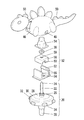
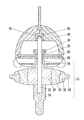
以下、図を参照して、本発明を適用した実施の形態について説明する。図1は、コマ玩具10の外観を示す図である。
Hereinafter, an embodiment to which the present invention is applied will be described with reference to the drawings. FIG. 1 is a view showing the appearance of the
コマ玩具10は、コマ本体20と、保持部52を内設する形象体46と、ラックベルト70とで構成されている。このコマ玩具10は、心棒に胴輪を軸止させた「胴輪ごま」を原形としているが、従来のコマに必要な紐を不要とし、ラックベルト70を用いてコマ玩具10を容易に回転させることを可能としている。また、コマ本体20の上方に、形象体46を配設し、遊戯者への趣向を高めている。また、このコマ玩具10は、コマ本体10が高速に回転している状態においても、形象体46は、コマ本体10と同一の速度で回転せず、コマ玩具10の回転速度に比べ、極めて遅い回転を行うと共に、形象体46の姿勢安定性を高め、形象体46の形状を視認することを可能としているものである。
The
まず図1を用いて、ラックベルト70の説明を行う。ラックベルト70は、断面を方形状にした棒状に形成され、該棒状の一側面には、ピニオンギアと歯合する歯部72が形成されている。また、棒状に形成されたラックベルト70の端部には、リング状に形成された指掛部74が形成され、ラックベルト70を使用時には、該指掛部74に指を掛けて使用するものである。
First, the
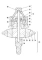
次に、図2及び図3を用いてコマ本体20の説明を行う。コマ本体20は、回転コマ軸22と、リング体32と、コマ軸カバー38などで構成されている。
Next, the
回転コマ軸22は、金属製で棒状体であり、樹脂部材26と、脱落防止具36が軸止されている。回転コマ軸22の上方先端は、頂点角度を約90度とした直円錐状に形成されたピボット24が形成される。また、回転コマ軸22の下方先端は、樹脂部材26と当接するようにコマ軸カバー38が嵌入されている。この回転コマ軸22の上方先端に形成されたピボット24で、保持部52を点接点で支持するものである。またピボット24は、コマ玩具10全体のバランスから円錐形状が好適である。尚、円錐形状の他に、正三角錐や、正四角錐となる正多角錐であっても構わない。
The
このように回転コマ軸22の上方先端に形成した直円錐形状の頂点による点接点で、保持部52を支持することによって、コマ本体10の回転は、極めて小さい回転力しか保持部52に伝達されず、保持部52は、コマ本体10の回転速度より、極めて遅い回転速度となる。また保持部52を内設した形象体46を、回転コマ軸22の回転方向とは、逆方向への回転力を加えると、回転コマ軸22の回転力が伝達されにくいため、容易に逆方向への回転を行うものである。また、保持部52を内設した形象体46が逆方向への回転をしても、正方向への回転する回転コマ軸22への抵抗は極めて小さく、回転コマ軸22への影響は極めて小さい。
By supporting the holding
次に回転コマ軸22の中央やや下の位置に軸止された樹脂部材26は、ポリアセタールなどの樹脂で厚肉円板状に形成され、樹脂部材26の上端面に該厚肉円板と同心軸とした円柱が形成され、該円柱の先端には、ピニオンギア28が形成されている。樹脂部材26は、該円柱の先端に形成されたピニオンギア28から、下端面まで貫通する孔が形成され、回転コマ軸22に軸止している。樹脂部材26の下端面は、コマ軸カバー38の上端面と当接されている。
Next, the
また、樹脂部材26の厚肉円板状に形成された外周には、金属でリング状に形成されたフライホイール30を嵌着している。リング状に形成されたフライホイール30の上端面と下端面は、中心から外周に向けて緩やかに内側に向けて傾斜した形に形成されている。このフライホイール30の外周を覆うようにリング体32を外嵌している、
Further, a
リング体32は、ABS・ポリアセタールなどの樹脂でリング状に形成され、リング体32の内周面が、フライホイール30の外周に外嵌するものである。このリング体32は、フライホイール30と同様に、リング体32の上端面と下端面の中央から外周に向けて緩やかに内側に向けて傾斜した形に形成されている。また、リング体32の外周面には、所定の間隔に厚肉で半円版状に形成された凸部である突起体34が設けられている。実施例では、突起体34の形状は、半円板状に形成された凸部としたが、この凸部の形状は、どのような形に形成されていてもよい。
The
また、このリング体32は、脱着自在に設けられている。他のコマ玩具と衝突させて遊戯させる場合に、突起体34の形状によって、他のコマ玩具との衝突状態に変化を与えることができる。このリング体32は、遊戯者の好みに応じて、他のコマ玩具より自コマ玩具10が優位になるように交換したり、他のコマ玩具との衝突によって、突起体34が欠損したり損耗したりするために交換することもある。
The
また、実施例のリング体32は、所定の間隔に凸部である突起体34が設けられているが、リング体32の中央に対して点対称の位置にそれぞれ突起体34が形成されていれば良い。
In addition, the
そして、リング体32は、図4(A)に示すように、その外周面に、半円柱状で、該半円柱の上端面の一端から対向する下端面の一端まで切断した傾斜面を有する突起体34や、図4(B)に示すように、リング体32の外周面に、直方体形状の突起体34を形成するようにしてもよい。このように突起体34を様々な形状に形成することにより、他のコマ玩具との衝突状態に変化を与えることができる。
As shown in FIG. 4A, the
さらに、図4(A)及び図4(B)に示すように、リング体32の内周面に、内周に沿って複数箇所に凸部35が形成され、該凸部35とフライホイール30とを弾性密着されるようにして固着することもできる。
Further, as shown in FIGS. 4A and 4B,
次に、図2及び図3に示す回転コマ軸22の下方先端で樹脂部材26の下面と当接するように嵌入されたコマ軸カバー38は、ポリアセタールなどの樹脂で棒形状に形成され、コマ軸カバー38の下方から中央にかけて、上方に比べて、やや細く形成されると共に、コマ軸カバー38の下端は、半球形状に形成されている。コマ軸カバー38の下端が半球形状に形成されていることにより、遊戯者が、コマ軸カバー38に半球形状部分に触れたり、コマ玩具10を掌で回転させたりする場合においても、怪我することを防止することを可能としている。また、このように、コマ軸カバー38の下端を半球形状に形成することによって、地面との摩擦を極めて小さくすることができる。
Next, the
また、コマ軸カバー38は、回転コマ軸22より脱着自在に設けられている。例えば、他のコマ玩具と衝突させて遊戯させる場合に、長さや太さの異なるコマ軸カバー38に交換することにより、他のコマ玩具との衝突状態に変化を与えられる。この他に、コマ軸カバー38は、半球形状に形成された下端が地面との摩耗によって、損耗した場合に交換される。またコマ玩具10を飾って展示する場合など、遊戯者の好みに応じて、コマ軸カバー38を交換することもある。
Further, the
実施例のコマ軸カバー38は、上述の形状のほかに、コマ軸カバー38の下端を広角な錐形状にしたり、コマ軸カバー38の棒形状を様々な長さ及び太さとして形成することもある。例えば、コマ軸カバー38の下端の半球形状の直径を大とし、溝を有する走行路などを走行させると、該溝内を高速に走行させることができる。また、コマ軸カバー38の半球形状の直径を小とすると、該溝内を低速に走行させることができる。
In addition to the above-described shape, the top-
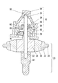
また、図5は、コマ本体20のフライホイール30とリング体32とコマ軸カバー38の別の実施例である。図5に示す回転コマ軸22に軸止された樹脂部材26に外嵌されたフライホイール30は、肉厚リング状に形成されている。これによりフライホイール30の製造工程を少なくすることを可能としている。
FIG. 5 shows another embodiment of the
また、リング体32は、底面板を有する厚肉リング状に形成され、リング体32の底面板には、回転コマ軸22と略同一径の孔(図示しない)が形成されている。このリング体32は、フライホイール30の外周及び下端面に外嵌し且つリング体32の床面板に形成された孔により、回転コマ軸22に軸止されている。
The
次に、コマ軸カバー38は、回転コマ軸22の下方先端でリング体32の下端面と当接するように嵌入されている。このようにコマ軸カバー38で、リング体32の下端面と当接させることにより、リング体32が、コマ本体20より脱落することを防止できる。
Next, the
そして、コマ軸カバー38を錐形状とし、コマ軸カバー38の上端の直径をリング体32に近くすれば、コマ玩具10を「べーごま」のように形成することもできる。
If the
次に、図2及び図3に示すように脱落防止具36は、樹脂部材26の上方に回転コマ軸22に軸止されている。脱落防止具36は、金属製又は樹脂製で円板状に形成されており、後述する上部保持枠58に上端面に形成された回転コマ軸22が貫通する孔59よりも外径が大である。従って、コマ玩具10の形象体46を挟持し、持ち上げると、脱落防止具36の下端面は、上部保持枠58の上端面と当接することによって、形象体46からコマ本体10が脱落するのを防止している。また、脱落防止具36の下端面は、緩やかな球形状に形成されている。この脱落防止具36は、図3に示すようにコマ玩具10が回転中においては、どの部材にも接触しない。
Next, as shown in FIGS. 2 and 3, the drop-
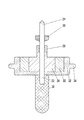
図2を用いて形象体46の説明を行う。形象体46は、キャラクター、動物、昆虫、乗り物、ロボットなど様々な物を模した形で重量を軽減するため中空に形成されている。また形象体46の両側面には、ラックベルト70を挿入するための孔48が形成されている。そして形象体46の幅は、フライホイール30の直径より短い幅で形成されており、コマ玩具10を使用時には、突起体34が形象体46の一部若しくは全部より突出している。この形象体46の略重心位置に、保持部52が配設されている。尚、形象体は、中空とする場合のみでなく、発泡スチロールなどの比重の極めて軽い樹脂で形成しつつ保持部を内設することもある。
The figure 46 will be described with reference to FIG. The
また、形象体46は、恐竜を模した形に形成され、恐竜の首及び尻尾を模した可動部50が、可動可能に配置されている。また、可動部50は、キャラクターの手や足を模して形成してもよい。さらに、遊戯者は、好みに応じて、首・尻尾、手、足となる可動部50の向きを変え、形象体46の姿勢を変えることができる。
The
また、自コマ玩具10が優位となるように可動部50の向き変えることにより、他のコマ玩具との衝突状態に変化を与えることができる。また、他のコマ玩具との衝突の衝撃により可動部50の向きが可動するように緩く固定しておくこともあり、他のコマ玩具との衝突状態に変化をもたらすこともある。
Further, by changing the direction of the
次に、図2及び図3を用いて保持部52の説明を行う。保持部52は、ピボット受け部54と、上部保持枠58と、下部保持枠62で構成される。
Next, the holding
ピボット受け部54は、ポリアセタールなどの樹脂素材を用い略円柱形状で中空に形成され、円柱の下端面を開口するようにして形成されている。また、円柱の下端は、方形状の鍔が形成されている。また、中空で円柱状に形成されたピボット受け部54の上端面の裏面に、頂点角度を約120度とした直円錐状の凹部となる円錐凹部56が形成されており、円錐凹部56の中央で、回転コマ軸22のピボット24が、点接点支持される。また、円錐凹部56の中央位置が、保持部52を含む形象体46の重心位置となるように配置され、ピボット受け部54を形象体46の重心位置の上方とし且つ回転コマ軸22のピボット24で点接点支持することにより、形象体46が、垂直且つ水平状態を保持することを可能としている。
The
上部保持枠58は、ポリアセタールなどの樹脂素材を用いて厚肉に方形状に形成し、上部保持枠58の上端面から下端面にかけて、回転コマ軸22が貫通する孔59が穿設されている。また、上端面側の孔59の直径は、回転コマ軸22の芯径のより大きく且つ脱落防止具36の直径より小さくし、回転コマ軸22を垂直とした時、回転コマ軸22が孔59の内周壁面に接触しないようにしている。また、上部保持枠58の下端面には、ラックベルト70を挿入するために、両側面まで貫通する凹部となるラックベルト挿入路60が形成されている。
The
ラックベルト70を挿入時に回転コマ軸22は、上部保持枠58の孔59の内周壁面と、ピボット受け部54の円錐凹部56の内周壁面にそれぞれ当接し、支持される。これにより、ラックベルト70の歯部72と、回転コマ軸22のピニオンギア28が歯合されるようになる。
When the
下部保持枠62は、ポリアセタールなどの樹脂を用いて厚肉で略コの字型に形成され、コの字型の開口側を上方としている。下部保持枠62の下方には、孔64が穿設されている。孔64は、保持部52若しくは回転コマ軸22が傾倒し、回転コマ軸22が、円錐凹部56の内周壁面と、孔59の内周壁面に接触しても、ピニオンギア28及び樹脂部材26が、孔64の内周壁面に接触しない大きさに穿設されている。そして、コの字型の両先端に、係合凸部66が形成されている。下部保持枠62のコの字型内に、ピボット受け部54の下端面と上部保持枠58の上端面を当接させた後、両部材を内包し、下部保持枠62の係合凸部66をピボット受け部54の鍔部と係合させ、ピボット受け部54及び上部保持枠58を支持するものである。また、回転コマ軸22が、どのような状態においても樹脂部材26の円柱や円柱上端のピニオンギア28などが、下部保持枠62の孔64内周壁面に接触しないようにしている。
The
このように、保持部52は、ピボット受け部54の下端面と、上部保持枠58の上端面を当接させ、下部保持枠62で、ピボット受け部54と上部保持枠58に外嵌し、ピボット受け部54と上部保持枠58を内包するようにして支持しているものである。
In this way, the holding
また、図7を用いて保持部52を用いない形象体46の説明を行う。形象体46の内部に、ピボット受け部80と、脱落防止板82が内設されている。また、形象体46のやや下方には、ラックベルト70を挿入するために、形象体46の両側面まで貫通し、凹部となるラックベルト挿入路60が形成されている。
Further, the figure 46 that does not use the holding
ピボット受け部80は、直方体状に形成され、形象体46の重心位置より上方の位置に、固着されている。また、ピボット受け部80の下端面に、回転コマ軸22の上方先端の円錐よりも広角な錐形状の凹部である円錐凹部56が形成されている。また、このピボット受け部80の形状は、直方体状としたが、円柱形状など、どのような形状に形成されてあっても良い。
The
次に、脱落防止板82は、板状に形成され、形象体46のやや下方で水平に内設されている。この脱落防止板82には、円錐凹部56の中心と同心位置に孔59が穿設されている。孔59の直径は、回転コマ軸22の芯径のより大きく且つ脱落防止具36の直径より小さくし、回転コマ軸22を垂直とした時、回転コマ軸22が孔59の内周壁面に接触しないようにしている。
Next, the drop-
ラックベルト70を挿入時に回転コマ軸22は、上述の実施例と同様に、脱落防止板82の孔59の内周壁面と、ピボット受け部80の円錐凹部56の内周壁面にそれぞれ当接し、支持される。これにより、ラックベルト70の歯部72と、回転コマ軸22のピニオンギア28が歯合されるようになる。
When the
このように、形象体46にピボット受け部80と、脱落防止板82を内設することにより、保持部52と同様の効果を得ることを可能としている。また、ピボット受け部80及び脱落防止板82を別の部材としたが、形象体46内のリブで、ピボット受け部80と脱落防止板82同等な形状に形成することによっても実施可能である。
Thus, by providing the
次にコマ玩具10のコマ本体20の回転させる方法について説明する。形象体46の両側面の孔50を介して上部保持枠58のラックベルト挿入路60にラックベルト70を挿入する。図6は、保持部52にラックベルト70を挿入した時の断面を示す図である。ラックベルト70を挿入すると、回転コマ軸22は、上部保持枠58の孔59の壁面と、ピボット受け部54の円錐凹部56の壁面にそれぞれ当接し、支持される。これにより、ラックベルト70の歯部72と、回転コマ軸22のピニオンギア28が歯合される。
Next, a method for rotating the
ラックベルト70の指掛部74に指を掛けて、コマ玩具10より、ラックベルト70を引き抜くことにより、ピニオンギア28を軸止した回転コマ軸22が高速に回転する。フライホイール30のジャイロ効果によって、高速回転した状態は、長時間にわたって保持されるようになる。このように、遊戯者は、形象体46の両側面の孔50を介して上部保持枠58のラックベルト挿入路60にラックベルト70を挿入し、その後ラックベルト70を引き抜くだけで、容易にコマ本体10を高速に回転させることを可能としている。
By placing a finger on the
コマ本体20が高速に回転している状態で、形象体46を挟持し、コマ玩具10を地面に置くことにより、コマ遊びを容易に行うことができる。コマ玩具の遊び方は、従来と同様であるが、他のコマ玩具と共に、緩やかな曲面となる地面に置くことによって、コマ玩具同士を衝突させて楽しめる。
While the
他のコマ玩具や障害物などにコマ玩具10が衝突することにより生じる揺れや、コマ本体20自体の回転による遠心力などの影響により、形象体46に揺れが生じるものであるが、傾いた状態でもピボット受け部54の円錐凹部56の直円錐状の凹部の中央で点接点されており、孔59の内周壁面に回転コマ軸22が接触しても、その摩擦抵抗は、極めて少なく、形象体46は、弥次郎兵衛の如く高い姿勢安定性を維持する。
The figure 46 is shaken by the influence of the shaking caused by the
また、コマ本体20が回転している状態でコマ玩具10を傾けて地面に置くと、コマ玩具10は、形象体46の垂直及び水平状態を維持し且つコマ本体20が傾いた状態を維持しつつ、円を描くように走行するようになる。また、緩やかに球面状に形成された円形の凹部に、コマ本体20が回転している状態でコマ玩具10を置くと、円形の凹部を中心に円及び楕円を描くように走行するようになる。
Further, when the
次に、コマ玩具10の遊戯方法として、中央に緩やかに球面状に形成された円形の凹部を有する遊技台(図示しない)で自コマ玩具10と他のコマ玩具を衝突させて楽しむことができる。また、中央に緩やかに球面状に形成された円形の凹部の外周にコマ玩具10用の複数の走行路を円形縁部に接続するように形成した遊戯台を用いることができる。
Next, as a play method of the
この場合の走行路としては、コマ軸カバー38の直径よりも大きな幅の溝が形成され、該溝は、左右で深さを変えて底面を傾斜させて形成している。また走行路の一端は、遊戯台の円形縁部に接続されており、他端側は、蛇行した走行路など様々な形状とした走行路が形成されている。
As a traveling path in this case, a groove having a width larger than the diameter of the
コマ本体20が回転したコマ玩具10を、走行路となる溝に置くと溝の底面の傾斜によって、溝の壁面とコマ軸カバー38は、当接するようになる。コマ玩具10は、溝壁面と当接し且つ回転するコマ軸カバー38によって、走行路となる溝内を走行するようになる。
When the
複数の走行路の各々他端側に自コマ玩具10及び他のコマ玩具を置き、走行路となる溝内を走行させると、両コマ玩具は、走行路内の走行を終え、走行路が接続された中央に緩やかに球面状に形成された円形の凹部内で回転するようになる。凹部内は、緩やかに球面状に形成されており、自コマ玩具10と他のコマ玩具は、互いに衝突を繰り返す。その結果、先に回転を止めたコマ玩具か、遊戯台の外部へと弾き飛ばされたコマ玩具が負けとなる遊びを行うことができる。
When the own
また、上述の走行路を例えばトラックの如く環状で複数形成し、自コマ玩具10と他のコマ玩具の走行スピードを競わせたりする遊戯を行い、楽しむこともできる。
In addition, a plurality of the above-described traveling paths are formed in a ring shape like a truck, for example, and a game in which the traveling speed of the own
以上説明したように構成することにより、コマ本体が回転しても、コマ本体の上方に配置した保持部を有する形象体が、コマ本体からの回転の影響を受け難くくし、コマ本体が回転中に形象体を視認しやすくするコマ玩具を提供することができる。また、図1及び図2に示した形象体46は、前後に可動部50を有し、左右は、コマ本体20のリング体32よりも狭く、前後には、リング体32よりも大きく形成している。前後左右の全周囲において、形象体46の最大幅をリング体32よりも小さくする場合や、形象体46の前後は、リング体32の外方に突出させつつ、可動部50を設けることなく形象体46をフライホイール30やリング体32よりも下方まで延設することもある。このように、好ましい実施例を挙げて本発明を説明したが、本発明はその実施例に限定されるものではなく、本発明の要旨の範囲内で種々に改変できる。
By configuring as described above, even when the frame main body rotates, the figure having the holding portion disposed above the frame main body is less affected by the rotation from the frame main body, and the frame main body is rotating. It is possible to provide a top toy that makes it easy to visually recognize a figure. 1 and 2 has a
10 コマ玩具
20 コマ本体
22 回転コマ軸
24 ピボット
26 樹脂部材
28 ピニオンギア
30 フライホイール
32 リング体
34 突起体
35 凸部
36 脱落防止具
38 コマ軸カバー
46 形象体
48 孔
50 可動部
52 保持部
54 ピボット受け部
56 円錐凹部
58 上部保持枠
59 孔
60 ラックベルト挿入路
62 下部保持枠
64 孔
66 係合凸部
70 ラックベルト
72 歯部
74 指掛部
80 ピボット受け部
82 脱落防止板
DESCRIPTION OF
Claims (7)
Priority Applications (2)
| Application Number | Priority Date | Filing Date | Title |
|---|---|---|---|
| JP2005303799A JP2007111144A (en) | 2005-10-19 | 2005-10-19 | Toy top |
| PCT/JP2006/321195 WO2007046535A1 (en) | 2005-10-19 | 2006-10-18 | Top toy |
Applications Claiming Priority (1)
| Application Number | Priority Date | Filing Date | Title |
|---|---|---|---|
| JP2005303799A JP2007111144A (en) | 2005-10-19 | 2005-10-19 | Toy top |
Publications (1)
| Publication Number | Publication Date |
|---|---|
| JP2007111144A true JP2007111144A (en) | 2007-05-10 |
Family
ID=37962619
Family Applications (1)
| Application Number | Title | Priority Date | Filing Date |
|---|---|---|---|
| JP2005303799A Pending JP2007111144A (en) | 2005-10-19 | 2005-10-19 | Toy top |
Country Status (2)
| Country | Link |
|---|---|
| JP (1) | JP2007111144A (en) |
| WO (1) | WO2007046535A1 (en) |
Cited By (1)
| Publication number | Priority date | Publication date | Assignee | Title |
|---|---|---|---|---|
| WO2015005608A1 (en) * | 2013-07-11 | 2015-01-15 | Choi Jong-Ill | Spinning top and spinning top play device using same |
Families Citing this family (5)
| Publication number | Priority date | Publication date | Assignee | Title |
|---|---|---|---|---|
| JP6145206B1 (en) * | 2016-09-05 | 2017-06-07 | 株式会社タカラトミー | Top toy set and launcher |
| JP6250203B1 (en) * | 2017-02-21 | 2017-12-20 | 株式会社タカラトミー | Top toy |
| JP1596151S (en) * | 2017-08-30 | 2018-01-29 | ||
| USD889563S1 (en) * | 2018-05-29 | 2020-07-07 | Spin Tricks Toys Inc. | Toy with spring mechanism |
| USD877260S1 (en) * | 2018-10-24 | 2020-03-03 | Tomy Company, Ltd. | Winder for launching apparatus for spinning top toy |
Family Cites Families (4)
| Publication number | Priority date | Publication date | Assignee | Title |
|---|---|---|---|---|
| JPH0727975Y2 (en) * | 1991-11-20 | 1995-06-28 | 株式会社学習研究社 | Top Toy |
| JP4088907B2 (en) * | 1998-12-28 | 2008-05-21 | 株式会社グッドハウス | Top |
| JP3588086B2 (en) * | 2002-04-17 | 2004-11-10 | 株式会社タカラ | Remote control top toy |
| JP3109118U (en) * | 2004-12-01 | 2005-05-12 | 株式会社タカラ | Top toy |
-
2005
- 2005-10-19 JP JP2005303799A patent/JP2007111144A/en active Pending
-
2006
- 2006-10-18 WO PCT/JP2006/321195 patent/WO2007046535A1/en active Application Filing
Cited By (3)
| Publication number | Priority date | Publication date | Assignee | Title |
|---|---|---|---|---|
| WO2015005608A1 (en) * | 2013-07-11 | 2015-01-15 | Choi Jong-Ill | Spinning top and spinning top play device using same |
| JP2016523177A (en) * | 2013-07-11 | 2016-08-08 | チェ ジョンイルCHOI, Jong−Ill | Top and top playing device using the same |
| US9643095B2 (en) | 2013-07-11 | 2017-05-09 | Jong-Ill CHOI | Spinning top and spinning top play device using same |
Also Published As
| Publication number | Publication date |
|---|---|
| WO2007046535A1 (en) | 2007-04-26 |
Similar Documents
| Publication | Publication Date | Title |
|---|---|---|
| JP2007111144A (en) | Toy top | |
| US20080175650A1 (en) | Combined Toy and Writing Instrument or Other Article | |
| WO2015062427A1 (en) | Bouncing toy spin-top | |
| CN104998416A (en) | Spinning toy game device | |
| TWM553111U (en) | Pet toy | |
| US4019738A (en) | Game device and game | |
| JP2005328976A (en) | Toy top | |
| JP3109118U (en) | Top toy | |
| JP5054154B2 (en) | Operation pieces, soccer play equipment, slalom play equipment, fighting sesame play equipment, and jump play equipment using operation pieces | |
| US3015907A (en) | Hoop toys | |
| JP3138102U (en) | Sword ball toy | |
| JP2009118895A (en) | Aquatic top | |
| JP2009247882A (en) | Multi-stage top | |
| JP4150773B2 (en) | Top toy with three-dimensional attachment and detachment accessories | |
| CN205084392U (en) | Rotatory toy recreation device | |
| JP3066857U (en) | Top toy | |
| JP3242379U (en) | toy | |
| JP3237307U (en) | toy | |
| JP6487582B1 (en) | Play equipment | |
| US10507397B2 (en) | Vibrating toy | |
| JP4429024B2 (en) | Popping game toy | |
| US20070072508A1 (en) | Flying saucer structure | |
| JP3230666U (en) | toy | |
| CN203540043U (en) | Toy gyro capable of rotating durably | |
| US6551167B1 (en) | Playground spinning element with noise making device |