JP2007107730A - Cooling system - Google Patents
Cooling system Download PDFInfo
- Publication number
- JP2007107730A JP2007107730A JP2005296026A JP2005296026A JP2007107730A JP 2007107730 A JP2007107730 A JP 2007107730A JP 2005296026 A JP2005296026 A JP 2005296026A JP 2005296026 A JP2005296026 A JP 2005296026A JP 2007107730 A JP2007107730 A JP 2007107730A
- Authority
- JP
- Japan
- Prior art keywords
- stop suction
- suction pressure
- compressors
- compressor
- cooling system
- Prior art date
- Legal status (The legal status is an assumption and is not a legal conclusion. Google has not performed a legal analysis and makes no representation as to the accuracy of the status listed.)
- Pending
Links
Images


Landscapes
- Devices That Are Associated With Refrigeration Equipment (AREA)
Abstract
Description
本発明は、蒸発器への冷媒取り込みを制御することによって冷却を行う複数の冷蔵冷凍機器と、並列接続の複数の圧縮機の選択的な稼動により能力可変を段階的に行うマルチ冷凍機とを備えた冷却システムに関する。 The present invention includes a plurality of refrigeration refrigerators that perform cooling by controlling refrigerant intake into an evaporator, and a multi refrigerator that performs variable capacity in stages by selectively operating a plurality of compressors connected in parallel. It is related with the provided cooling system.
スーパーマーケット等の比較的大型の店舗にはマルチ冷凍機と称される共用冷凍機を用いた冷却システムが一般に使用されている。この冷却システムは、オープン型冷蔵ショーケースや扉付き冷凍庫等から成る複数の冷蔵冷凍機器と、複数の圧縮機を有するマルチ冷凍機と、各冷蔵冷凍機器及びマルチ冷凍機の運転を管理するメインコントローラとを備えている。 In a relatively large store such as a supermarket, a cooling system using a common refrigerator called a multi refrigerator is generally used. This cooling system includes a plurality of refrigeration equipment comprising an open type refrigerated showcase, a door-mounted freezer, etc., a multi-freezer having a plurality of compressors, and a main controller for managing the operation of each refrigeration equipment and multi-freezer And.
各冷蔵冷凍機器は蒸発器と該蒸発器に冷媒を取り込むための電磁弁と実庫内温度を検出するための温度センサを有し、実庫内温度が設定庫内温度となるように電磁弁の開閉して冷媒取り込みを制御することによって冷却を行う。マルチ冷凍機は並列接続の複数の圧縮機と各圧縮機の吸入側に設けられた複数の圧縮機停止用圧力スイッチを有し、動作圧力値が異なる圧力スイッチの信号に基づき各圧縮機をオンオフ駆動することによって複数の圧縮機の選択的な稼動による段階的な能力可変を行う。 Each refrigeration equipment has an evaporator, a solenoid valve for taking refrigerant into the evaporator, and a temperature sensor for detecting the temperature in the actual cabinet, and the solenoid valve so that the actual chamber temperature becomes the set chamber temperature. Cooling is performed by controlling the refrigerant intake by opening and closing the. The multi-refrigerator has a plurality of compressors connected in parallel and a plurality of compressor stop pressure switches provided on the suction side of each compressor, and each compressor is turned on and off based on signals from pressure switches having different operating pressure values. By driving, the capacity is gradually changed by selectively operating a plurality of compressors.
最近では、各圧縮機の回転数を制御することによって能力可変を行うマルチ冷凍機も実用に供されている。このマルチ冷凍機は能力可変をリニアに行えるため、能力可変を段階的に行うタイプのマルチ冷凍機に比べて省エネルギーに貢献できる。
能力可変をリニアに行うタイプのマルチ冷凍機を用いた冷却システムは省エネルギーによるランニングコスト低減等の恩恵を得ることができるが、能力可変を段階的に行うタイプのマルチ冷凍機を用いた冷凍システムに比べてシステム設置に係る初期コストがかかる。 A cooling system using a multi-chiller of a type that performs variable capacity linearly can obtain benefits such as a reduction in running costs due to energy saving, but a refrigeration system using a multi-freezer of a type that performs variable capacity in stages. Compared to the initial cost for system installation.
つまり、能力可変を段階的に行うタイプのマルチ冷凍機でも能力可変をリニアに行うタイプのマルチ冷凍機と近似の能力可変を行えるようにすれば、システム設置に係る初期コストを抑えることができると共に省エネルギーによるランニングコスト低減等の恩恵も得ることができる。 In other words, it is possible to reduce the initial cost related to system installation by making it possible to perform a variable capacity that is similar to that of a multi-chiller that linearly varies the capacity even in a multi-chiller that performs variable capacity in stages. Benefits such as reduced running costs due to energy savings can also be obtained.
本発明は前記事情に鑑みて創作されたもので、その目的とするところは、システム設置に係る初期コストを抑えることができると共に省エネルギーによるランニングコスト低減等の恩恵も得ることができる冷却システムを提供することにある。 The present invention was created in view of the above circumstances, and the object of the present invention is to provide a cooling system that can suppress initial costs related to system installation and can also obtain benefits such as reduction of running costs due to energy saving. There is to do.
前記目的を達成するため、本発明は、蒸発器への冷媒取り込みを制御することによって冷却を行う複数の冷蔵冷凍機器と、並列接続の複数の圧縮機の選択的な稼動により能力可変を段階的に行うマルチ冷凍機とを備えた冷却システムであって、店内温度と店内湿度に基づいて店内エンタルピを求め該店内エンタルピに応じた圧縮機毎の停止吸入圧力を設定する手段と、設定された圧縮機毎の停止吸入圧力に基づいて複数の圧縮機をオンオフ駆動する手段とを備える、ことをその特徴とする。 In order to achieve the above-mentioned object, the present invention gradually changes the capacity by selectively operating a plurality of refrigeration equipment that performs cooling by controlling refrigerant intake into the evaporator and a plurality of compressors connected in parallel. A cooling system comprising a multi-refrigerator for performing an in-store enthalpy based on the in-store temperature and in-store humidity and setting a stop suction pressure for each compressor in accordance with the in-store enthalpy, and a set compression And a means for driving the plurality of compressors on and off based on the stop suction pressure for each machine.
この冷却システムによれば、店内温度と店内湿度に基づいて店内エンタルピを求め該店内エンタルピに応じた圧縮機毎の停止吸入圧力を設定しているので、各冷蔵冷凍機器から特殊な運転データを収集することなく、圧縮機毎の停止吸入圧力を適切に設定することができる。しかも、店内エンタルピに応じた圧縮機毎の停止吸入圧力に基づき各圧縮機をオンオフ駆動しているので、複数の圧縮機の選択的な稼動による段階的な能力可変を的確に行うことができる。つまり、能力可変を段階的に行うタイプのマルチ冷凍機でありながらも、能力可変をリニアに行うタイプのマルチ冷凍機と近似の能力可変を行うことができるので、システム設置に係る初期コストを抑えることができると共に省エネルギーによるランニングコスト低減等の恩恵も得ることができる。 According to this cooling system, the store enthalpy is obtained based on the store temperature and the store humidity, and the stop suction pressure for each compressor is set according to the store enthalpy, so special operation data is collected from each refrigeration unit. Without stopping, the stop suction pressure for each compressor can be set appropriately. In addition, since each compressor is driven on and off based on the stop suction pressure for each compressor corresponding to the in-store enthalpy, it is possible to accurately perform stepwise capacity variation by selectively operating a plurality of compressors. In other words, even though it is a type of multi-chiller that changes capacity in stages, it can perform variable capacity similar to that of a type of multi-chiller that changes capacity linearly, thus reducing the initial cost of system installation. In addition, it is possible to obtain benefits such as reduced running costs due to energy saving.
また、本発明は、蒸発器への冷媒取り込みを制御することによって冷却を行う複数の冷蔵冷凍機器と、並列接続の複数の圧縮機の選択的な稼動により能力可変を段階的に行うマルチ冷凍機とを備えた冷却システムであって、日時に応じた圧縮機毎の停止吸入圧力を設定する手段と、設定された圧縮機毎の停止吸入圧力に基づいて複数の圧縮機をオンオフ駆動する手段とを備える、ことをその特徴とする。 The present invention also provides a plurality of refrigeration refrigerators that perform cooling by controlling refrigerant intake into the evaporator, and a multi refrigerator that performs variable capacity in stages by selectively operating a plurality of parallel-connected compressors. A means for setting a stop suction pressure for each compressor according to the date and time, a means for driving on and off a plurality of compressors based on the set stop suction pressure for each compressor, and It is characterized by comprising.
この冷却システムによれば、日時に応じた圧縮機毎の停止吸入圧力を設定しているので、各冷蔵冷凍機器から特殊な運転データを収集することなく、圧縮機毎の停止吸入圧力を適切に設定することができる。しかも、日時に応じた圧縮機毎の停止吸入圧力に基づき各圧縮機をオンオフ駆動しているので、複数の圧縮機の選択的な稼動による段階的な能力可変を的確に行うことができる。つまり、能力可変を段階的に行うタイプのマルチ冷凍機でありながらも、能力可変をリニアに行うタイプのマルチ冷凍機と近似の能力可変を行うことができるので、システム設置に係る初期コストを抑えることができると共に省エネルギーによるランニングコスト低減等の恩恵も得ることができる。 According to this cooling system, since the stop suction pressure for each compressor is set according to the date and time, the stop suction pressure for each compressor is appropriately set without collecting special operation data from each refrigeration equipment. Can be set. In addition, since each compressor is driven on and off based on the stop suction pressure for each compressor according to the date and time, it is possible to accurately perform stepwise capacity variation by selectively operating a plurality of compressors. In other words, even though it is a type of multi-chiller that changes capacity in stages, it can perform variable capacity similar to that of a type of multi-chiller that changes capacity linearly, thus reducing the initial cost of system installation. In addition, it is possible to obtain benefits such as reduced running costs due to energy saving.
本発明によれば、システム設置に係る初期コストを抑えることができると共に省エネルギーによるランニングコスト低減等の恩恵も得ることができる冷却システムを提供できる。 ADVANTAGE OF THE INVENTION According to this invention, the cooling system which can suppress the initial cost concerning system installation and can also obtain benefits, such as a running cost reduction by energy saving, can be provided.
本発明の前記目的とそれ以外の目的と、構成特徴と、作用効果は、以下の説明と添付図面によって明らかとなる。 The above object and other objects, structural features, and operational effects of the present invention will become apparent from the following description and the accompanying drawings.
図1〜図4は本発明の一実施形態を示す。図1は冷却システムの全体構成図、図2は圧縮機毎の停止吸入圧力の設定に係る処理フローを示す図、図3は圧縮機毎の停止吸入圧力を設定する際に用いられるデータテーブルを示す図、図4は圧縮機の選択的稼動に係る処理フロー示す図である。 1 to 4 show an embodiment of the present invention. FIG. 1 is an overall configuration diagram of a cooling system, FIG. 2 is a diagram showing a processing flow relating to setting of a stop suction pressure for each compressor, and FIG. 3 is a data table used when setting a stop suction pressure for each compressor. FIG. 4 is a diagram showing a processing flow relating to the selective operation of the compressor.
まず、図1を参照して、冷却システムの全体構成について説明する。図1中の1〜4は冷蔵冷凍機器、5はマルチ冷凍機、6はメインコントローラ、RP1は冷媒往き管、RP2は冷媒戻り管、SL1,SL2は信号線である。 First, the entire configuration of the cooling system will be described with reference to FIG. In FIG. 1, 1 to 4 are refrigerated refrigerators, 5 is a multi refrigerator, 6 is a main controller, RP1 is a refrigerant forward pipe, RP2 is a refrigerant return pipe, and SL1 and SL2 are signal lines.
各冷蔵冷凍機器1〜4はオープン型冷蔵ショーケースや扉付き冷凍庫等から成り、店内の所定位置に設置されている。各冷蔵冷凍機器1〜4は、蒸発器1a〜4aと、蒸発器1a〜4aの入口側に設けられた膨張弁1b〜4bと、膨張弁1b〜4bの入口側に設けられた電磁弁1c〜4cと、冷却空気を循環するための庫内ファン1d〜4dと、実庫内温度(吹き出し温度)TA1〜TA4を検出するための庫内温度センサ1e〜4eと、コントローラ1f〜4fと、設定庫内温度TS1〜TS4を定めるための庫内温度設定器1g〜4gとを少なくとも備える。因みに、蒸発器(1a〜4a)への冷媒取り込みを制御する電磁弁(1c〜4c)と膨張弁(1b〜4b)の構成は、両者の機能を併せ持つ電子式膨張弁で代用することもできる。各冷蔵冷凍機器1〜4の蒸発器1a〜4aは冷媒往き管RP1及び冷媒戻り管RP2を介してマルチ冷凍機5の冷媒用出口及び冷媒用入口に並列に接続されている。
Each of the refrigerated refrigerators 1 to 4 includes an open-type refrigerated showcase, a freezer with a door, and the like, and is installed at a predetermined position in the store. Each refrigeration equipment 1 to 4 includes an
各コントローラ1f〜4fはマイクロコンピュータ構成の制御部と駆動部と通信部と検知部とを有し、各通信部は信号線SL1を介してメインコントローラ6に接続され、各検知部には庫内温度センサ1e〜4eが接続されている。各駆動部は制御部からの信号に基づいて電磁弁1c〜4cの開閉駆動と庫内ファン1d〜1dのオンオフ駆動等を行う。各制御部のメモリには、実庫内温度(TA1〜TA4)が設定庫内温度(TS1〜TS4)となるように電磁弁(1c〜4c)を開閉して冷媒取り込みを制御することによって冷却を行うための冷却プログラムと、設定庫内温度(TS1〜TS4)と実庫内温度(TA1〜TA4)等をメインコントローラ6に伝送するための通信プログラム等が格納されている。
Each
マルチ冷凍機5は、並列接続の複数(図中は3台)の圧縮機5a〜5cと、圧縮機5a〜5cの吐出側に設けられた凝縮器5dと、圧縮機5a〜5cの吸入側に設けられた実吸入圧力(PA)検出用の圧力センサ5eと、コントローラ5fとを少なくとも備える。因みに、各圧縮機5a〜5cは同じ能力のものであってもよいし、異なる能力のものであってもよい。マルチ冷凍機5の冷媒用出口(凝縮器5bの出口側)には冷媒往き管RP1の基端が接続され、冷媒用入口(圧縮機5a〜5cの吸入側)には冷媒戻り管RP2の終端が接続されている。
The
コントローラ5fはマイクロコンピュータ構成の制御部と駆動部と通信部と検知部とを有し、通信部は信号線SL2を介してメインコントローラ6に接続され、検知部には圧力センサ5eが接続されている。駆動部は制御部からの信号に基づいて各圧縮機5a〜5cのオンオフ駆動等を行う。制御部のメモリには、複数の圧縮機5a〜5cを選択的に稼動させるための後述の圧縮機選択稼動プログラムと、実吸入圧力PA等をメインコントローラ6に伝送するための通信プログラム等が記憶されている。
The
メインコントローラ6は、マイクロコンピュータ構成の制御部6aと、入力キーやディスプレイを含む設定部6bと、検知部6cと、店内温度TIを検出するための店内温度センサ6dと、店内湿度UIを検出するための店内湿度センサ6eと、通信部6fと、通信部6fに接続されたコネクタ6gとを少なくとも備える。
The
店内温度センサ6dと店内湿度センサ6eは各冷蔵冷凍機器1〜4及び店内空調機からの熱的影響を受け難い店内位置に設置されており、検知部6cに接続されている。また、コネクタ6gには信号線SL1,SL2の端が接続されている。さらに、制御部6aのメモリには、圧縮機5a〜5c毎の停止吸入圧力PSa〜PScを設定するための後述の停止吸入圧力設定プログラムと、後述の各種データテーブルと、設定後の停止吸入圧力PSa〜PScをマルチ冷凍機5に伝送するための通信プログラム等が格納されている。
The in-
次に、図2及び図3を参照して、メインコントローラ6で実行される圧縮機毎の停止吸入圧力の設定に係る処理フローを説明する。
Next, with reference to FIG. 2 and FIG. 3, a processing flow relating to setting of the stop suction pressure for each compressor executed by the
システム起動後は、店内温度センサ6dと店内湿度センサ6eで検出された今現在の店内温度TIと店内湿度UIに基づいて店内エンタルピEを求める(図2のステップS11)。ここでは、予め用意した店内温度TIと店内湿度UIをパラメータとするデータテーブル(図示省略)を利用し、該当する店内温度TIと店内湿度UIとから店内エンタルピEを選定する。勿論、この店内エンタルピEは、データテーブルを利用せずに、店内温度TIと店内湿度UIとを変数とした計算式によって求めることも可能である。
After the system is started, the in-store enthalpy E is obtained based on the current in-store temperature TI and in-store humidity UI detected by the in-
店内エンタルピEを求めた後は、該店内エンタルピEに応じた圧縮機5a〜5c毎の停止吸入圧力PSa〜PScを設定する(図2のステップS12)。ここでは、予め用意した店内エンタルピEをパラメータとする図3のデータテーブルを利用し、該当する店内エンタルピEから圧縮機5a〜5c毎の停止吸入圧力PSa〜PScを選定する。例えば、店内エンタルピEがE5に該当するときには、圧縮機5aの停止吸入圧力PSaとして0.36MPa、圧縮機5bの停止吸入圧力PSbとして0.44MPa、圧縮機5cの停止吸入圧力PScとして0.51MPaがそれぞれ選定される。勿論、この圧縮機5a〜5c毎の停止吸入圧力PSa〜PScは、データテーブルを利用せずに、店内エンタルピEを変数とした計算式によって求めることも可能である。
After obtaining the in-store enthalpy E, stop suction pressures PSa to PSc for the
店内エンタルピEに応じた圧縮機5a〜5c毎の停止吸入圧力PSa〜PScを設定した後は、設定した圧縮機5a〜5c毎の停止吸入圧力PSa〜PScをマルチ冷凍機5のコントローラ5fに伝送する(図2のステップS13)。
After setting the stop suction pressures PSa to PSc for each of the
次に、図4を参照して、マルチ冷凍機5のコントローラ5fで実行される圧縮機の選択的稼動に係る処理フローについて説明する。
Next, with reference to FIG. 4, a processing flow related to the selective operation of the compressor executed by the
マルチ冷凍機5のコントローラ5fはメインコントローラ6からの圧縮機5a〜5c毎の停止吸入圧力PSa〜PScの伝送を待ち、伝送があったときにはこの圧縮機5a〜5c毎の停止吸入圧力PSa〜PScを制御部のメモリに記憶する(図4のステップS21,S22)。
The
そして、圧縮機5a〜5c毎の停止吸入圧力PSa〜PScに基づき各圧縮機5a〜5cをオンオフ駆動することによって複数の圧縮機5a〜5cの選択的な稼動による段階的な能力可変を行う(図4のステップS23)。
Then, the
例えば、店内エンタルピEが図3のE5に該当していて圧縮機5a〜5c毎の停止吸入圧力PSa〜PScとして0.36MPa,0.44MPa,0.51MPaが伝送された場合は、実吸入圧力PAが0.51MPaよりも大きいときは全ての圧縮機5a〜5cを稼動し、実吸入圧力PAが0.51MPa≧PA>0.44MPaの範囲内にあるときは圧縮機5a,5bを稼動し、実吸入圧力PAが0.44MPa≧PA>0.36MPaの範囲内にあるときは圧縮機5aを稼動し、実吸入圧力PAが0.36MPa以下のときは全ての圧縮機5a〜5cを停止するように複数の圧縮機5a〜5cを選択的に稼動して能力可変を段階的に行う。
For example, when the in-store enthalpy E corresponds to E5 in FIG. 3 and 0.36 MPa, 0.44 MPa, and 0.51 MPa are transmitted as the stop suction pressures PSa to PSc for the
設定された圧縮機5a〜5c毎の停止吸入圧力PSa〜PScに基づいて複数の圧縮機5a〜5cがオンオフ駆動されているときに、新たな停止吸入圧力PSa〜PScがメインコントローラ6から伝送されたときには、前記と同様に、伝送された新たな停止吸入圧力PSa〜PScを制御部のメモリに記憶し、該停止吸入圧力PSa〜PScに基づいて各圧縮機5a〜5cをオンオフ駆動することによって複数の圧縮機5a〜5cの選択的な稼動による段階的な能力可変を行う(図4のステップS24)。
When the plurality of
前述の冷却システムによれば、店内温度TIと店内湿度UIに基づいて店内エンタルピEを求め該店内エンタルピEに応じた圧縮機5a〜5c毎の停止吸入圧力PSa〜PScを設定しているので、各冷蔵冷凍機器1〜4から特殊な運転データを収集することなく、圧縮機5a〜5c毎の停止吸入圧力PSa〜PScを適切に設定することができる。しかも、店内エンタルピEに応じた圧縮機5a〜5c毎の停止吸入圧力PSa〜PScに基づき各圧縮機5a〜5cをオンオフ駆動しているので、複数の圧縮機5a〜5cの選択的な稼動による段階的な能力可変を的確に行うことができる。
According to the above-described cooling system, since the store enthalpy E is obtained based on the store temperature TI and the store humidity UI, the stop suction pressures PSa to PSc for the
つまり、能力可変を段階的に行うタイプのマルチ冷凍機5でありながらも、能力可変をリニアに行うタイプのマルチ冷凍機と近似の能力可変を行うことができるので、システム設置に係る初期コストを抑えることができると共に省エネルギーによるランニングコスト低減等の恩恵も得ることができる。
In other words, although it is a type of
また、既存店舗において能力可変を段階的に行うタイプのマルチ冷凍機を用いた冷却システムが未だ多く設置され使用されている現状にあっては、該冷却システムに前記冷却システムと同様の制御を行えるような改良を加えるだけで同様の作用効果を得ることができる。 Moreover, in the existing situation where many cooling systems using a multi-chiller of the type in which the capacity is changed in stages are still installed and used, the same control as the cooling system can be performed on the cooling system. Similar effects can be obtained simply by making such improvements.
つまり、能力可変を段階的に行うタイプのマルチ冷凍機を用いた既設の冷却システムを新しい冷却システムに交換することなく、制御系の部分的な改良によって能力可変をリニアに行うタイプのマルチ冷凍機と近似の能力可変を行って省エネルギーを図ることができるので、実用上のメリットが極めて大きい。 In other words, the multi-cooler of the type that linearly changes the capacity by partially improving the control system without replacing the existing cooling system using the multi-cooler of the type that changes the capacity stepwise with a new cooling system. Since it is possible to save energy by changing the approximate capacity, there is a great practical advantage.
図5〜図10は前記冷却システムにあって圧縮機5a〜5c毎の停止吸入圧力PSa〜PScをより適切に設定するための処理フローをそれぞれ示す。
5 to 10 show process flows for more appropriately setting the stop suction pressures PSa to PSc for the
図5に示した処理フローは能力過剰時における停止吸入圧力PSa〜PScの変更に関するものである。ここでは、設定された圧縮機5a〜5c毎の停止吸入圧力PSa〜PScに基づいて各圧縮機5a〜5cをオンオフ駆動しているときの各圧縮機5a〜5cの所定時間当たりのオンオフ回数をカウントし、カウントされたオンオフ回数が予め定めた値以上のときは能力過剰とみなして前記停止吸入圧力PSa〜PScを高値の停止吸入圧力PSa〜PScに変更している(ステップS31〜S34参照)。前記停止吸入圧力PSa〜PScを高値の停止吸入圧力PSa〜PScに変更する方法としては、図3のデータテーブルで選定された今現在の停止吸入圧力PSa〜PScを同データテーブルの1段下或いは2段下の停止吸入圧力PSa〜PScに置換する方法と、図3のデータテーブルで選定された今現在の停止吸入圧力PSa〜PScにそれぞれ所定の値を加算する方法の何れかが採用できる。
The processing flow shown in FIG. 5 relates to the change of the stop suction pressures PSa to PSc when the capacity is excessive. Here, the number of on / off times of each
図6の処理フローは能力過剰時における停止吸入圧力PSa〜PScの変更に関するものである。ここでは、設定された圧縮機5a〜5c毎の停止吸入圧力PSa〜PScに基づいて各圧縮機5a〜5cをオンオフ駆動しているときの実吸入圧力PAの所定時間当たりの平均値をApa求め、求められた平均値Apaが予め定めた値以下のときは能力過剰とみなして前記停止吸入圧力PSa〜PScを高値の停止吸入圧力PSa〜PScに変更している(ステップS41〜S44参照)。前記停止吸入圧力PSa〜PScを高値の停止吸入圧力PSa〜PScに変更する方法としては、図3のデータテーブルで選定された今現在の停止吸入圧力PSa〜PScを同データテーブルの1段下或いは2段下の停止吸入圧力PSa〜PScに置換する方法と、図3のデータテーブルで選定された今現在の停止吸入圧力PSa〜PScにそれぞれ所定の値を加算する方法の何れかが採用できる。
The processing flow of FIG. 6 relates to the change of the stop suction pressures PSa to PSc when the capacity is excessive. Here, based on the set stop suction pressures PSa to PSc for the
図7の処理フローは能力不足時における停止吸入圧力PSa〜PScの変更に関するものである。ここでは、設定された圧縮機5a〜5c毎の停止吸入圧力PSa〜PScに基づいて各圧縮機5a〜5cをオンオフ駆動しているときの各冷蔵冷凍機器1〜4の実庫内温度TA1〜TA4の推移を認識し、認識された実庫内温度TA1〜TA4の推移が設定庫内温度TS1〜TS4よりも高い傾向があるときは能力不足とみなして前記停止吸入圧力PSa〜PScを低値の停止吸入圧力PSa〜PScに変更している(ステップS51〜S54参照)。前記停止吸入圧力PSa〜PScを低値の停止吸入圧力PSa〜PScに変更する方法としては、図3のデータテーブルで選定された今現在の停止吸入圧力PSa〜PScを同データテーブルの1段上或いは2段上の停止吸入圧力PSa〜PScに置換する方法と、図3のデータテーブルで選定された今現在の停止吸入圧力PSa〜PScからそれぞれ所定の値を減算する方法の何れかが採用できる。
The processing flow of FIG. 7 relates to the change of the stop suction pressures PSa to PSc when the capacity is insufficient. Here, the actual internal temperature TA1 of each refrigeration refrigerator 1 to 4 when the
図8の処理フローは冷蔵冷凍機器1〜4の少なくとも1台が除霜運転に入ったときにおける停止吸入圧力PSa〜PScの変更に関するものである。ここでは、設定された圧縮機5a〜5c毎の停止吸入圧力PSa〜PScに基づいて各圧縮機5a〜5cをオンオフ駆動しているときに除霜に入った冷蔵冷凍機器(1〜4)の有無を判断し、除霜に入った冷蔵冷凍機器(1〜4)が有るときにその数と庫内設定温度を把握し、除霜に入った冷蔵冷凍機器(1〜4)の数と庫内設定温度に基づいて能力過剰分を相殺するように前記停止吸入圧力PSa〜PScを高値の停止吸入圧力PSa〜PScに変更している(ステップS61〜S64参照)。前記停止吸入圧力PSa〜PScを高値の停止吸入圧力PSa〜PScに変更する方法としては、図3のデータテーブルで選定された今現在の停止吸入圧力PSa〜PScを同データテーブルの1段下或いは2段下の停止吸入圧力PSa〜PScに置換する方法と、図3のデータテーブルで選定された今現在の停止吸入圧力PSa〜PScにそれぞれ所定の値を加算する方法の何れかが採用できる。
The processing flow of FIG. 8 relates to the change of the stop suction pressures PSa to PSc when at least one of the refrigeration refrigerators 1 to 4 enters the defrosting operation. Here, based on the set stop suction pressures PSa to PSc for the
図9の処理フローは冷蔵冷凍機器1〜4の少なくとも1台が除霜運転から通常運転に復帰したときにおける停止吸入圧力PSa〜PScの変更に関するものである。ここでは、設定された圧縮機5a〜5c毎の停止吸入圧力PSa〜PScに基づいて各圧縮機5a〜5cをオンオフ駆動しているときに除霜から復帰した冷蔵冷凍機器(1〜4)の有無を判断し、除霜から復帰した冷蔵冷凍機器(1〜4)が有るときにその数と庫内設定温度を把握し、除霜から復帰した冷蔵冷凍機器(1〜4)の数と庫内設定温度に基づいて迅速な冷却が行えるように前記停止吸入圧力PSa〜PScを低値の停止吸入圧力PSa〜PScに変更している(ステップS71〜S74参照)。変更後の低値の停止吸入圧力PSa〜PScに基づいて各圧縮機5a〜5cをオンオフ駆動する時間は短時間で構わないため、同時間に15分程度の制限を設けて、制限時間経過後に変更前の停止吸入圧力PSa〜PScに再変更してもよい。前記停止吸入圧力PSa〜PScを低値の停止吸入圧力PSa〜PScに変更する方法としては、図3のデータテーブルで選定された今現在の停止吸入圧力PSa〜PScを同データテーブルの1段上或いは2段上の停止吸入圧力PSa〜PScに置換する方法と、図3のデータテーブルで選定された今現在の停止吸入圧力PSa〜PScからそれぞれ所定の値を減算する方法の何れかが採用できる。
The processing flow of FIG. 9 relates to the change of the stop suction pressures PSa to PSc when at least one of the refrigeration units 1 to 4 returns from the defrosting operation to the normal operation. Here, based on the set stop suction pressures PSa to PSc for the
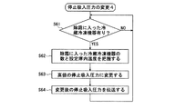
図10の処理フローは冷蔵冷凍機器1〜4の少なくとも1台にナイトカバーが装着されたときにおける停止吸入圧力PSa〜PScの変更に関するものである。ここでは、設定された圧縮機5a〜5c毎の停止吸入圧力PSa〜PScに基づいて各圧縮機5a〜5cをオンオフ駆動しているときにナイトカバーが装着された冷蔵冷凍機器(1〜4)の有無を判断し、ナイトカバーが装着された冷蔵冷凍機器(1〜4)が有るときその数と庫内設定温度を把握し、ナイトカバーが装着された冷蔵冷凍機器(1〜4)の数と庫内設定温度に基づいて能力過剰分を相殺するように前記停止吸入圧力PSa〜PScを高値の停止吸入圧力PSa〜PScに変更している(ステップS81〜S84参照)。前記停止吸入圧力PSa〜PScを高値の停止吸入圧力PSa〜PScに変更する方法としては、図3のデータテーブルで選定された今現在の停止吸入圧力PSa〜PScを同データテーブルの1段下或いは2段下の停止吸入圧力PSa〜PScに置換する方法と、図3のデータテーブルで選定された今現在の停止吸入圧力PSa〜PScにそれぞれ所定の値を加算する方法の何れかが採用できる。
The processing flow of FIG. 10 relates to the change of the stop suction pressures PSa to PSc when the night cover is attached to at least one of the refrigeration refrigerators 1 to 4. Here, the refrigerator-freezer (1-4) with which the night cover was mounted | worn when each
図11は本発明の他の実施形態を示す冷却システムの全体構成図である。同図に示した冷却システムが図1に示した冷却システムと異なるところは、メインコントローラ6から検知部6cと店内温度センサ6dと店内湿度センサ6eを排除し、検知部6cの代わりに日時データを制御部6aに送出するタイマ部6hを設けた点にあり、メインコントローラ6の制御部6aのメモリには、店内エンタルピをパラメータとした停止吸入圧力選定用のデータテーブルの代わりに、日時をパラメータとした停止吸入圧力選定用のデータテーブル(図示省略)が記憶されている。
FIG. 11 is an overall configuration diagram of a cooling system showing another embodiment of the present invention. The cooling system shown in the figure is different from the cooling system shown in FIG. 1 except that the
メインコントローラ6は、システム起動後、タイマ部6hから送出された日時データに基づき該日時に応じた圧縮機5a〜5c毎の停止吸入圧力PSa〜PScを選定してマルチ冷凍機5のコントローラ5fに伝送する。マルチ冷凍機5のコントローラ5fは伝送された圧縮機5a〜5c毎の停止吸入圧力PSa〜PScに基づき前記と同様に各圧縮機5a〜5cをオンオフ駆動することによって複数の圧縮機5a〜5cの選択的な稼動による段階的な能力可変を行う。
After starting the system, the
この冷却システムによれば、日時に応じた圧縮機5a〜5c毎の停止吸入圧力PSa〜PScを設定しているので、各冷蔵冷凍機器1〜4から特殊な運転データを収集することなく、圧縮機5a〜5c毎の停止吸入圧力PSa〜PScを適切に設定することができる。しかも、日時に応じた圧縮機5a〜5c毎の停止吸入圧力PSa〜PScに基づき各圧縮機5a〜5cをオンオフ駆動しているので、複数の圧縮機5a〜5cの選択的な稼動による段階的な能力可変を的確に行うことができる。
According to this cooling system, since the stop suction pressures PSa to PSc for each of the
つまり、能力可変を段階的に行うタイプのマルチ冷凍機5でありながらも、能力可変をリニアに行うタイプのマルチ冷凍機と近似の能力可変を行うことができるので、システム設置に係る初期コストを抑えることができると共に省エネルギーによるランニングコスト低減等の恩恵も得ることができる。
In other words, although it is a type of
また、既存店舗において能力可変を段階的に行うタイプのマルチ冷凍機を用いた冷却システムが未だ多く設置され使用されている現状にあっては、該冷却システムに前記冷却システムと同様の制御を行えるような改良を加えるだけで同様の作用効果を得ることができる。 Moreover, in the existing situation where many cooling systems using a multi-chiller of the type in which the capacity is changed in stages are still installed and used, the same control as the cooling system can be performed on the cooling system. Similar effects can be obtained simply by making such improvements.
つまり、能力可変を段階的に行うタイプのマルチ冷凍機を用いた既設の冷却システムを新しい冷却システムに交換することなく、制御系の部分的な改良によって能力可変をリニアに行うタイプのマルチ冷凍機と近似の能力可変を行って省エネルギーを図ることができるので、実用上のメリットが極めて大きい。 In other words, the multi-cooler of the type that linearly changes the capacity by partially improving the control system without replacing the existing cooling system using the multi-cooler of the type that changes the capacity stepwise with a new cooling system. Since it is possible to save energy by changing the approximate capacity, there is a great practical advantage.
因みに、図5〜図10を引用して説明した停止吸入圧力の変更に係る処理フローは図11に示した冷却システムにも適用することができる。 Incidentally, the processing flow relating to the change of the stop suction pressure described with reference to FIGS. 5 to 10 can also be applied to the cooling system shown in FIG. 11.
尚、前述の実施形態では、マルチ冷凍機5として3台の圧縮機5a〜5cを並列接続したものを示したが、4台以上或いは2台の圧縮機を並列接続したマルチ冷凍機を代わりに用いた場合でも本発明を適用して前記同様の作用効果を得ることができる。
In the above-described embodiment, the three
また、前述の実施形態では、4台の冷蔵冷凍機器1〜4を備えた冷却システムを例示しが、冷蔵冷凍機器の台数が5以上の冷却システムであっても本発明を適用して前記同様の作用効果を得ることができる。 In the above-described embodiment, a cooling system including four refrigeration refrigerators 1 to 4 is illustrated, but the present invention is applied to a cooling system having five or more refrigeration refrigerators in the same manner as described above. The effect of this can be obtained.
1〜4…冷蔵冷凍機器、1a〜4a…蒸発器、1c〜4c…電磁弁、1f〜4f…コントローラ、5…マルチ冷凍機、5a〜5c…圧縮機、5e…圧力センサ、5f…コントローラ、6…メインコントローラ、6a…制御部、6d…店内温度センサ、6e…店内湿度センサ、6h…タイマ部。 DESCRIPTION OF SYMBOLS 1-4 ... Refrigerated refrigeration equipment, 1a-4a ... Evaporator, 1c-4c ... Solenoid valve, 1f-4f ... Controller, 5 ... Multi refrigerator, 5a-5c ... Compressor, 5e ... Pressure sensor, 5f ... Controller, 6 ... main controller, 6a ... control unit, 6d ... store temperature sensor, 6e ... store humidity sensor, 6h ... timer unit.
Claims (8)
店内温度と店内湿度に基づいて店内エンタルピを求め該店内エンタルピに応じた圧縮機毎の停止吸入圧力を設定する手段と、
設定された圧縮機毎の停止吸入圧力に基づいて複数の圧縮機をオンオフ駆動する手段とを備える、
ことを特徴とする冷却システム。 Cooling system comprising a plurality of refrigeration equipment that cools by controlling refrigerant intake into the evaporator, and a multi-chiller that changes the capacity in stages by selectively operating a plurality of compressors connected in parallel Because
Means for obtaining an in-store enthalpy based on the in-store temperature and in-store humidity and setting a stop suction pressure for each compressor according to the in-store enthalpy;
Means for driving the plurality of compressors on and off based on the set stop suction pressure for each compressor.
A cooling system characterized by that.
日時に応じた圧縮機毎の停止吸入圧力を設定する手段と、
設定された圧縮機毎の停止吸入圧力に基づいて複数の圧縮機をオンオフ駆動する手段とを備える、
ことを特徴とする冷却システム。 Cooling system comprising a plurality of refrigeration equipment that cools by controlling refrigerant intake into the evaporator, and a multi-chiller that changes the capacity in stages by selectively operating a plurality of compressors connected in parallel Because
Means for setting the stop suction pressure for each compressor according to the day and time;
Means for driving the plurality of compressors on and off based on the set stop suction pressure for each compressor.
A cooling system characterized by that.
カウントされたオンオフ回数が予め定めた値以上のときに前記停止吸入圧力を高値の停止吸入圧力に変更する手段をさらに備える、
ことを特徴とする請求項1または2に記載の冷却システム。 Means for counting the number of ON / OFF times per predetermined time of each compressor when a plurality of compressors are ON / OFF driven based on the set stop suction pressure for each compressor;
Means for changing the stop suction pressure to a high stop suction pressure when the counted number of on / off operations is equal to or greater than a predetermined value;
The cooling system according to claim 1 or 2 characterized by things.
求められた平均値が予め定めた値以下のときに前記停止吸入圧力を高値の停止吸入圧力に変更する手段をさらに備える、
ことを特徴とする請求項1または2に記載の冷却システム。 Means for obtaining an average value per predetermined time of the actual suction pressure when the plurality of compressors are driven on and off based on the set stop suction pressure for each compressor;
Means for changing the stop suction pressure to a high stop suction pressure when the calculated average value is equal to or less than a predetermined value;
The cooling system according to claim 1 or 2 characterized by things.
認識された実庫内温度の推移が設定庫内温度よりも高い傾向があるときに前記停止吸入圧力を低値の停止吸入圧力に変更する手段をさらに備える、
ことを特徴とする請求項1または2に記載の冷却システム。 Means for recognizing the transition of the internal temperature of each refrigeration unit when driving a plurality of compressors on and off based on the set stop suction pressure for each compressor;
And further comprising means for changing the stop suction pressure to a low stop suction pressure when the recognized transition of the temperature in the actual warehouse tends to be higher than the set interior temperature.
The cooling system according to claim 1 or 2 characterized by things.
除霜に入った冷蔵冷凍機器が有るときにその数と庫内設定温度を把握する手段と、
除霜に入った冷蔵冷凍機器の数と庫内設定温度に基づいて前記停止吸入圧力を高値の停止吸入圧力に変更する手段をさらに備える、
ことを特徴とする請求項1または2に記載の冷却システム。 Means for determining the presence or absence of a refrigeration unit that has entered defrosting when driving a plurality of compressors on and off based on the set stop suction pressure for each compressor;
Means for grasping the number and set temperature inside the refrigerator when there are refrigerated refrigerators that have entered defrosting;
Further comprising means for changing the stop suction pressure to a high stop suction pressure based on the number of refrigerated refrigeration equipment that has entered defrost and the set temperature in the refrigerator,
The cooling system according to claim 1 or 2 characterized by things.
除霜から復帰した冷蔵冷凍機器が有るときにその数と庫内設定温度を把握する手段と、
除霜から復帰した冷蔵冷凍機器の数と庫内設定温度に基づいて前記停止吸入圧力を低値の停止吸入圧力に変更する手段をさらに備える、
ことを特徴とする請求項1または2に記載の冷却システム。 Means for determining the presence or absence of refrigeration equipment that has returned from defrosting when a plurality of compressors are driven on and off based on the set stop suction pressure for each compressor;
Means for grasping the number and the set temperature in the refrigerator when there is a refrigerated refrigeration apparatus restored from defrosting;
Further comprising means for changing the stop suction pressure to a low stop suction pressure based on the number of refrigerated refrigeration equipment restored from defrost and the set temperature in the refrigerator,
The cooling system according to claim 1 or 2 characterized by things.
ナイトカバーが装着された冷蔵冷凍機器が有るときその数と庫内設定温度を把握する手段と、
ナイトカバーが装着された冷蔵冷凍機器の数と庫内設定温度に基づいて前記停止吸入圧力を高値の停止吸入圧力に変更する手段をさらに備える、
ことを特徴とする請求項1または2に記載の冷却システム。 Means for determining the presence or absence of a refrigeration unit equipped with a night cover when driving a plurality of compressors on and off based on the set stop suction pressure for each compressor;
Means for grasping the number and the set temperature inside the refrigerator when there are refrigerated refrigerators equipped with night covers;
Further comprising means for changing the stop suction pressure to a high stop suction pressure based on the number of refrigerated refrigeration equipment fitted with a night cover and the set temperature in the refrigerator,
The cooling system according to claim 1 or 2 characterized by things.
Priority Applications (1)
| Application Number | Priority Date | Filing Date | Title |
|---|---|---|---|
| JP2005296026A JP2007107730A (en) | 2005-10-11 | 2005-10-11 | Cooling system |
Applications Claiming Priority (1)
| Application Number | Priority Date | Filing Date | Title |
|---|---|---|---|
| JP2005296026A JP2007107730A (en) | 2005-10-11 | 2005-10-11 | Cooling system |
Publications (1)
| Publication Number | Publication Date |
|---|---|
| JP2007107730A true JP2007107730A (en) | 2007-04-26 |
Family
ID=38033734
Family Applications (1)
| Application Number | Title | Priority Date | Filing Date |
|---|---|---|---|
| JP2005296026A Pending JP2007107730A (en) | 2005-10-11 | 2005-10-11 | Cooling system |
Country Status (1)
| Country | Link |
|---|---|
| JP (1) | JP2007107730A (en) |
Cited By (8)
| Publication number | Priority date | Publication date | Assignee | Title |
|---|---|---|---|---|
| JP2010078198A (en) * | 2008-09-25 | 2010-04-08 | Sanyo Electric Co Ltd | Cooling system |
| JP2010078230A (en) * | 2008-09-26 | 2010-04-08 | Sanyo Electric Co Ltd | Cooling system |
| KR101032106B1 (en) | 2008-12-16 | 2011-05-02 | (주)에스코프로 | Method of operating chiller system for improving energy efficiency and subsidiary equipment for the method |
| JP2013015281A (en) * | 2011-07-05 | 2013-01-24 | Daikin Industries Ltd | Condensing unit set and refrigeration device equipped with the same |
| JP2013032915A (en) * | 2011-07-29 | 2013-02-14 | Espec Corp | Environmental test device |
| JPWO2021240615A1 (en) * | 2020-05-25 | 2021-12-02 | ||
| WO2022195854A1 (en) * | 2021-03-19 | 2022-09-22 | 三菱電機株式会社 | Freezer device |
| JP7493675B2 (en) | 2021-03-19 | 2024-05-31 | 三菱電機株式会社 | Refrigeration equipment |
Citations (4)
| Publication number | Priority date | Publication date | Assignee | Title |
|---|---|---|---|---|
| JPH1062019A (en) * | 1996-08-15 | 1998-03-06 | Sanyo Electric Co Ltd | Controller for compressor and refrigerator provided therewith |
| JPH10141784A (en) * | 1996-11-12 | 1998-05-29 | Hitachi Ltd | Refrigerator |
| JP2003083660A (en) * | 2001-09-11 | 2003-03-19 | Sanden Corp | Showcase cooler |
| JP2003130522A (en) * | 2001-10-18 | 2003-05-08 | Sanden Corp | Operation system of inverter refrigerator |
-
2005
- 2005-10-11 JP JP2005296026A patent/JP2007107730A/en active Pending
Patent Citations (4)
| Publication number | Priority date | Publication date | Assignee | Title |
|---|---|---|---|---|
| JPH1062019A (en) * | 1996-08-15 | 1998-03-06 | Sanyo Electric Co Ltd | Controller for compressor and refrigerator provided therewith |
| JPH10141784A (en) * | 1996-11-12 | 1998-05-29 | Hitachi Ltd | Refrigerator |
| JP2003083660A (en) * | 2001-09-11 | 2003-03-19 | Sanden Corp | Showcase cooler |
| JP2003130522A (en) * | 2001-10-18 | 2003-05-08 | Sanden Corp | Operation system of inverter refrigerator |
Cited By (12)
| Publication number | Priority date | Publication date | Assignee | Title |
|---|---|---|---|---|
| JP2010078198A (en) * | 2008-09-25 | 2010-04-08 | Sanyo Electric Co Ltd | Cooling system |
| US20110167853A1 (en) * | 2008-09-25 | 2011-07-14 | Sanyo Electric Co., Ltd. | Cooling system |
| US9157671B2 (en) | 2008-09-25 | 2015-10-13 | Panasonic Intellectual Property Management Co., Ltd. | Cooling system |
| JP2010078230A (en) * | 2008-09-26 | 2010-04-08 | Sanyo Electric Co Ltd | Cooling system |
| KR101032106B1 (en) | 2008-12-16 | 2011-05-02 | (주)에스코프로 | Method of operating chiller system for improving energy efficiency and subsidiary equipment for the method |
| JP2013015281A (en) * | 2011-07-05 | 2013-01-24 | Daikin Industries Ltd | Condensing unit set and refrigeration device equipped with the same |
| JP2013032915A (en) * | 2011-07-29 | 2013-02-14 | Espec Corp | Environmental test device |
| JPWO2021240615A1 (en) * | 2020-05-25 | 2021-12-02 | ||
| WO2021240615A1 (en) * | 2020-05-25 | 2021-12-02 | 三菱電機株式会社 | Refrigeration cycle device |
| JP7309063B2 (en) | 2020-05-25 | 2023-07-14 | 三菱電機株式会社 | refrigeration cycle equipment |
| WO2022195854A1 (en) * | 2021-03-19 | 2022-09-22 | 三菱電機株式会社 | Freezer device |
| JP7493675B2 (en) | 2021-03-19 | 2024-05-31 | 三菱電機株式会社 | Refrigeration equipment |
Similar Documents
| Publication | Publication Date | Title |
|---|---|---|
| KR101705528B1 (en) | Refrigerator and controlling method of the same | |
| EP3040656B1 (en) | Refrigerator and method for controlling the same | |
| EP2116796B1 (en) | Refrigerating storage cabinet | |
| WO2018042611A1 (en) | Refrigeration air conditioning system | |
| CN108885054B (en) | Refrigerator and control method thereof | |
| JP2007107730A (en) | Cooling system | |
| US20060236707A1 (en) | Refrigerator controlling method | |
| KR101517248B1 (en) | Control method for refrigerator | |
| US11371768B2 (en) | Refrigerator and method for controlling the same | |
| JP2010078272A (en) | Air-conditioning and refrigerating system | |
| KR102198955B1 (en) | Refrigerator and method for controlling the same | |
| KR20190050080A (en) | Refrigerator and method for controlling the same | |
| JP2008138914A (en) | Refrigerating device and method of returning refrigerating machine oil | |
| US20070137226A1 (en) | Refrigerator and method for controlling the refrigerator | |
| JP2008209022A (en) | Multi-air conditioner | |
| KR20070066836A (en) | Method of controlling refrigerator | |
| JP6048549B1 (en) | Refrigeration equipment | |
| KR102617277B1 (en) | Refrigerator and method for controlling the same | |
| KR100757109B1 (en) | Refrigerator and controlling method thereof | |
| KR100743753B1 (en) | Refrigerator and controlling method thereof | |
| KR20200062698A (en) | Refrigerator and method for controlling the same | |
| JP2003329354A (en) | Controller for refrigerator-freezer | |
| KR20120011654A (en) | Refrigerator and controlling method of the same | |
| JPH10281615A (en) | Cooling device for show case | |
| JP4845560B2 (en) | Cooling system |
Legal Events
| Date | Code | Title | Description |
|---|---|---|---|
| A621 | Written request for application examination |
Free format text: JAPANESE INTERMEDIATE CODE: A621 Effective date: 20080926 |
|
| A977 | Report on retrieval |
Free format text: JAPANESE INTERMEDIATE CODE: A971007 Effective date: 20100901 |
|
| A131 | Notification of reasons for refusal |
Free format text: JAPANESE INTERMEDIATE CODE: A131 Effective date: 20100903 |
|
| A02 | Decision of refusal |
Free format text: JAPANESE INTERMEDIATE CODE: A02 Effective date: 20110105 |