JP2007106934A - Hot melt adhesive sheet, interior for vehicle and method for interior for vehicle - Google Patents
Hot melt adhesive sheet, interior for vehicle and method for interior for vehicle Download PDFInfo
- Publication number
- JP2007106934A JP2007106934A JP2005300583A JP2005300583A JP2007106934A JP 2007106934 A JP2007106934 A JP 2007106934A JP 2005300583 A JP2005300583 A JP 2005300583A JP 2005300583 A JP2005300583 A JP 2005300583A JP 2007106934 A JP2007106934 A JP 2007106934A
- Authority
- JP
- Japan
- Prior art keywords
- melt adhesive
- hot melt
- adhesive sheet
- reinforcing fiber
- main body
- Prior art date
- Legal status (The legal status is an assumption and is not a legal conclusion. Google has not performed a legal analysis and makes no representation as to the accuracy of the status listed.)
- Granted
Links
Images
Landscapes
- Vehicle Interior And Exterior Ornaments, Soundproofing, And Insulation (AREA)
- Adhesive Tapes (AREA)
- Adhesives Or Adhesive Processes (AREA)
Abstract
Description
この発明は、ホットメルト接着シート、このホットメルト接着シートが用いられた車両用内装品及びこの車両用内装品の製造方法に関する。 The present invention relates to a hot melt adhesive sheet, a vehicle interior product using the hot melt adhesive sheet, and a method of manufacturing the vehicle interior product.
従来、車両用の天井は、下記特許文献1に記載されているように、所定の剛性を有する基材と、この基材の下両及び上面にそれぞれ接着されたガラス繊維等からなる第1、第2強化繊維層と、この第1、第2強化繊維層にそれぞれ接着された表面材及び裏面材とを備えている。基材と第1、第2強化繊維層とは、液状イソシアネート等の液状の接着剤によって接着されている。これは、液状の接着剤が安価であり、その分だけ天井の製造費を低減することができるからである。第1、第2強化繊維層と表面材及び裏面材とは、ホットメルト接着シートによってそれぞれ接着されている。ホットメルト接着シートは、各繊維層と表面材及び裏面材とを接着するのみならず、基材と各繊維層とを接着する液状の接着剤が天井の外面、特に表面材の表面に染み出すのを防止している。 Conventionally, as described in Patent Document 1 below, a vehicular ceiling includes a base material having a predetermined rigidity and glass fibers or the like that are respectively bonded to the lower and upper surfaces of the base material. A second reinforcing fiber layer, and a front material and a back material respectively bonded to the first and second reinforcing fiber layers are provided. The base material and the first and second reinforcing fiber layers are bonded with a liquid adhesive such as liquid isocyanate. This is because the liquid adhesive is inexpensive and the manufacturing cost of the ceiling can be reduced accordingly. The first and second reinforcing fiber layers are bonded to the front surface material and the back surface material by a hot melt adhesive sheet, respectively. The hot melt adhesive sheet not only bonds each fiber layer to the surface material and the back material, but also a liquid adhesive that bonds the base material to each fiber layer oozes out to the outer surface of the ceiling, especially the surface of the surface material. Is preventing.
上記従来の車両用天井においては、吸音性能が低いという問題があった。すなわち、第1、第2強化繊維層は、主として天井の強度向上のために用いられているのであるが、強化繊維間に隙間があるので吸音効果も有している。ところが、表面材と第1強化繊維層との間にホットメルト接着シートを設けると、ホットメルト接着シートが車内の騒音を反射してしまう。このため、第1、第2強化繊維層まで達する騒音の量が少なくなってしまう。この結果、第1、第2繊維強化層による吸音効果が小さくなり、天井の吸音性能が低くなっていたのである。 The conventional vehicle ceiling has a problem of low sound absorption performance. That is, the first and second reinforcing fiber layers are mainly used for improving the strength of the ceiling, but also have a sound absorbing effect because there is a gap between the reinforcing fibers. However, when a hot melt adhesive sheet is provided between the surface material and the first reinforcing fiber layer, the hot melt adhesive sheet reflects noise in the vehicle. For this reason, the amount of noise reaching the first and second reinforcing fiber layers is reduced. As a result, the sound absorption effect by the first and second fiber reinforced layers is reduced, and the sound absorption performance of the ceiling is lowered.
この発明は、上記問題を解決するためになされたもので、この発明に係るホットメルト接着シートは、ホットメルト接着剤からなるシート状の本体と、上記本体の内部に島状に埋設されたホットメルト接着剤からなる混在物とを備え、上記混在物の融点が上記本体の融点より低く設定されていることを特徴としている。
この場合、上記本体及び上記混在物が、融点を除いて互いに同一であるホットメルト接着剤によって構成されていることが望ましい。
この発明に係る車両用内装品は、所定の剛性を有する基材と、この基材の両面にそれぞれ接着された第1及び第2強化繊維層と、上記第1、第2強化繊維層にそれぞれホットメルト接着シートを介して接着された表面材及び裏面材とを備えた車両用内装材において、上記第1強化繊維層と上記表面材とを接着するための上記ホットメルト接着シートとして、請求項1又は2に記載のホットメルト接着シートが用いられていることを特徴としている。
この発明に係る車両用内装品の製造方法は、所定の剛性を有する基材と、この基材の両面にそれぞれ接着された第1及び第2強化繊維層と、上記第1、第2強化繊維層にそれぞれ接着された表面材及び裏面材とを備えた車両用内装材の製造方法において、上記第1強化繊維層と上記表面材とを接着するための上記ホットメルト接着シートとして請求項1又は2に記載のホットメルト接着シートが用いられ、上記第1強化繊維層と上記表面材との接着に際しては、上記混在物が溶融し、かつ上記本体が軟化するように、上記ホットメルト接着シートが加熱されることを特徴としている。
The present invention has been made to solve the above problems, and a hot melt adhesive sheet according to the present invention includes a sheet-like main body made of a hot melt adhesive, and a hot body embedded in an island shape inside the main body. And a mixture composed of a melt adhesive, and the melting point of the mixture is set lower than the melting point of the main body.
In this case, it is desirable that the main body and the mixture are composed of hot melt adhesives that are the same except for the melting point.
The vehicle interior product according to the present invention includes a base material having a predetermined rigidity, first and second reinforcing fiber layers bonded to both surfaces of the base material, and the first and second reinforcing fiber layers, respectively. In a vehicle interior material provided with a front surface material and a back surface material bonded via a hot melt adhesive sheet, the hot melt adhesive sheet for bonding the first reinforcing fiber layer and the surface material. The hot melt adhesive sheet according to 1 or 2 is used.
A method for manufacturing an interior product for a vehicle according to the present invention includes a base material having a predetermined rigidity, first and second reinforcing fiber layers bonded to both surfaces of the base material, and the first and second reinforcing fibers. In the manufacturing method of the interior material for vehicles provided with the surface material and back surface material which were each adhere | attached on the layer, As said hot-melt-adhesive sheet for adhere | attaching said 1st reinforcement fiber layer and said surface material, 2 is used, and when the first reinforcing fiber layer and the surface material are bonded, the hot melt adhesive sheet is used so that the mixture melts and the main body softens. It is characterized by being heated.
上記特徴構成を有するこの発明に係るホットメルト接着シートによって例えば車両用天井の強化繊維層と表面材とを接着する場合には、強化繊維層、ホットメルト接着シート及び表面材を積層した後、ホットメルト接着シートを加熱する。この場合、接着シートは、混在物が溶融し、かつ本体が軟化するように加熱される。溶融した混在物は、本体から外部に流れ出す。この結果、本体の内部に空孔が生じ、本体が連続気泡タイプの多孔質構造になる。したがって、接着後のホットメルト接着シートは、室内の騒音を基材側へ通過させる。ホットメルト接着シートを通過した室内の騒音は、強化繊維層によって吸収される。よって、この発明に係るホットメルト接着シートを用いて強化繊維層と表面材とを接着した車両用天井によれば、高い吸音性能が得られる。 For example, when the reinforcing fiber layer of the vehicle ceiling and the surface material are bonded by the hot melt adhesive sheet according to the present invention having the above-described characteristic configuration, the hot fiber adhesive layer, the hot melt adhesive sheet, and the surface material are laminated, The melt adhesive sheet is heated. In this case, the adhesive sheet is heated so that the mixture is melted and the main body is softened. The molten mixture flows out from the main body. As a result, pores are generated inside the main body, and the main body has an open-cell type porous structure. Therefore, the hot-melt adhesive sheet after bonding allows room noise to pass to the substrate side. The room noise that has passed through the hot melt adhesive sheet is absorbed by the reinforcing fiber layer. Therefore, according to the vehicle ceiling in which the reinforcing fiber layer and the surface material are bonded using the hot melt adhesive sheet according to the present invention, high sound absorption performance can be obtained.
以下、この発明を実施するための最良の形態を、図面を参照して説明する。
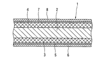
図1は、この発明に係る車両用天井(車両用内装品)1を示す。この天井1は、基材2と、この基材2の下面及び上面にそれぞれ接着固定された下強化繊維層(第1強化繊維層)3及び上強化繊維層(第2強化繊維層)4と、下強化繊維層3の下面に第1ホットメルト接着シート(ホットメルト接着シート)5を介して接着固定された表面材6と、上強化繊維層(第2強化繊維層)4の上面に第2ホットメルト接着シート7を介して接着固定された裏面材8とによって構成されている。
The best mode for carrying out the present invention will be described below with reference to the drawings.
FIG. 1 shows a vehicle ceiling (vehicle interior product) 1 according to the present invention. The ceiling 1 includes a base material 2, a lower reinforcing fiber layer (first reinforcing fiber layer) 3 and an upper reinforcing fiber layer (second reinforcing fiber layer) 4 that are bonded and fixed to the lower surface and the upper surface of the base material 2, respectively. The surface material 6 bonded and fixed to the lower surface of the lower reinforcing fiber layer 3 via the first hot melt adhesive sheet (hot melt adhesive sheet) 5 and the upper surface of the upper reinforcing fiber layer (second reinforcing fiber layer) 4 2 It is comprised with the back surface material 8 adhere | attached and fixed through the hot-melt-adhesive sheet 7. FIG.
基材2は、例えばポリエチレンやポリプロピレン等の樹脂からなる発泡材によって構成されており、天井1全体を一定の形状に維持するだけの所定の剛性(強度)を有している。基材2は、樹脂からなる中実の素材によって構成してもよい。 The base material 2 is made of a foam material made of a resin such as polyethylene or polypropylene, and has a predetermined rigidity (strength) sufficient to maintain the entire ceiling 1 in a certain shape. The substrate 2 may be made of a solid material made of resin.
下強化繊維層3は、基材2を補強して天井1全体の剛性をさらに向上させるとともに、天井1全体を所定の形状に維持するためのものであり、ガラス繊維を層状に堆積することによって構成されている。下強化繊維層3は、ガラス繊維マットやガラス繊維クロスを用いて構成すること可能である。また、ガラス繊維に代えて炭素繊維その他の無機繊維を用いてもよい。下強化繊維層3は、基材2の下面に接触する各強化繊維が基材2に接着されるのみならず、強化繊維どうしが互いに接着されている。下強化繊維層3を基材2に接着するとともに、強化繊維どうしを接着する接着剤としては、液状イソシアネート等の液状の接着剤(図示せず)が用いられている。 The lower reinforcing fiber layer 3 reinforces the base material 2 to further improve the rigidity of the entire ceiling 1, and maintains the entire ceiling 1 in a predetermined shape. By depositing glass fibers in layers, It is configured. The lower reinforcing fiber layer 3 can be configured using a glass fiber mat or glass fiber cloth. Further, carbon fibers and other inorganic fibers may be used instead of glass fibers. In the lower reinforcing fiber layer 3, not only the reinforcing fibers contacting the lower surface of the substrate 2 are bonded to the substrate 2, but also the reinforcing fibers are bonded to each other. A liquid adhesive (not shown) such as liquid isocyanate is used as an adhesive for adhering the lower reinforcing fiber layer 3 to the substrate 2 and adhering the reinforcing fibers.
上強化繊維層4は、基材2の上面に接着固定されている点が下強化繊維層3と異なるだけであり、下強化繊維層3と実質的に同一の構成を有している。 The upper reinforcing fiber layer 4 is different from the lower reinforcing fiber layer 3 only in that the upper reinforcing fiber layer 4 is bonded and fixed to the upper surface of the substrate 2, and has substantially the same configuration as the lower reinforcing fiber layer 3.
表面材6は、天井1が設けられる車両の車内に臨む表面(下面)を構成するものであり、TPO(サーモプラスチックオレフィン)やPVC(ポリ塩化ビニル)等からなるプラスチックシートであって、多数の小さな貫通孔を有するもの、トリコット等ファブリック、不織布、又はそれらの上面にクッション性を有するフォーム層(図示せず)が固着されたもの等が適宜用いられる。表面材6がフォーム層を有する場合には、フォーム層が下強化繊維層3に接着固定される。 The surface material 6 constitutes a surface (lower surface) facing the inside of the vehicle on which the ceiling 1 is provided, and is a plastic sheet made of TPO (thermoplastic olefin), PVC (polyvinyl chloride), and the like. A material having a small through hole, a fabric such as tricot, a nonwoven fabric, or a material in which a foam layer (not shown) having a cushioning property is fixed to the upper surface thereof is appropriately used. When the surface material 6 has a foam layer, the foam layer is bonded and fixed to the lower reinforcing fiber layer 3.
裏面材8は、天井1の上面を構成するものであり、不織布やプラスチックシート等の適宜のシートが用いられる。 The back material 8 constitutes the upper surface of the ceiling 1, and an appropriate sheet such as a nonwoven fabric or a plastic sheet is used.
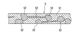
第1ホットメルト接着シート5は、下強化繊維層3と表面材6とを接着するものであり、接着に供される前と後では内部構造が変化する。まず、接着に供される前の第1ホットメルト接着シート5について説明すると、シート5は、図3に示すように、シート状をなす本体51と、この本体51内に埋設された混在物52とを有している。本体5は、常温では固化し、所定の温度に加熱されると溶融するポリエチレンやポリプロピレン等のホットメルト接着剤によって構成されており、20μm〜300μm程度の厚さを有している。
The first hot melt adhesive sheet 5 bonds the lower reinforcing fiber layer 3 and the surface material 6, and the internal structure changes before and after being used for bonding. First, the first hot melt adhesive sheet 5 before being subjected to bonding will be described. As shown in FIG. 3, the sheet 5 includes a sheet-like
一方、混在物52は、本体51より所定の温度だけ融点が低いホットメルト接着剤によって構成されている。混在物52を構成するホットメルト接着剤としては、本体51を構成するホットメルト接着剤より融点が低い点を除き、本体51を構成するホットメルト接着剤と同一のものを用いるのが望ましい。材質が同一で融点が異なる二つのホットメルト接着剤は、重合度を変えることによって得られる。つまり、本体51を構成するホットメルト接着剤の重合度を高くし、混在物52を構成するホットメルト接着剤の重合度を低くすることにより、混在物52の融点を本体51の融点より低くすることができる。混在物52は、塊状、層状等の各種の形状をもって本体51の内部にランダムに、しかも全体としてはほぼ一定の密度で埋設されている。大部分の混在物52は、本体51の少なくとも上下いずれかの面に、直接に又は互いに連なった他の混在物52を介して露出している。
On the other hand, the
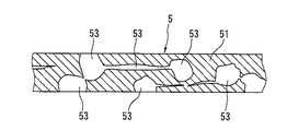
接着に供された後の第1ホットメルト接着シート5は、図2に示すように、本体51の内部に多数の空孔53を有している。空孔53は、混在物52が溶融して本体51から外部に流出することによって形成されたものである。したがって、空孔53は、混在物52とほぼ同一の形状を有している。しかも、各空孔53は、本体51の少なくとも上下いずれか一方の面から直接に、又は他の空孔53を介して外部に開放されている。このような空孔53が形成された結果、接着に供された後の第1ホットメルト接着剤5は、連続気泡を有する多孔質構造体と同様な内部構造になっている。
As shown in FIG. 2, the first hot-melt adhesive sheet 5 after being subjected to bonding has a large number of
第1ホットメルト接着シート5は、次のようにして製造することができる。まず、本体51を構成する樹脂を溶融するとともに、混在物52を構成する樹脂を溶融する。そして、両溶融樹脂を混合する。混合割合は、本体51による基材2と下強化繊維層3との接着強度、空孔53による吸音効果の大きさ、基材2と下強化繊維層3とを接着する液状の接着剤に対する本体51の透過阻止性を考慮して決定される。その後、混合した樹脂をシート状に成形して固化させることにより、第1ホットメルト接着シート5が得られる。
The first hot melt adhesive sheet 5 can be manufactured as follows. First, the resin constituting the
第2ホットメルト接着シート7は、第1ホットメルト接着シート5と同一に構成されている。そこで、第2ホットメルト接着剤7についての説明は省略する。なお、第2ホットメルト接着シート7については、全体が本体だけで構成されたホットメルト接着シートを用いてもよい。 The second hot melt adhesive sheet 7 is configured the same as the first hot melt adhesive sheet 5. Therefore, description of the second hot melt adhesive 7 is omitted. In addition, about the 2nd hot-melt-adhesive sheet 7, you may use the hot-melt-adhesive sheet in which the whole was comprised only by the main body.
上記構成の車両用天井1において、基材2と下強化繊維層3を接着する液状の接着剤は、第1ホットメルト接着シート5の各空孔53を通って表面材6側へ向かおうとする。ところが、シート5の各空孔53が小さいので、液状の接着剤がシート5を通過することはほとんどない。したがって、液状の接着剤が表面材6から下方へ染み出して天井1の美観が損なわれることを防止することができる。また、接着に供された後の第1ホットメルト接着シート5の内部構造が連続気泡タイプの多孔質構造になっているので、車内の騒音はシート5を通過する。そして、下強化繊維層3及び上強化繊維層4において吸収される。したがって、天井1の吸音性能を向上させることができる。特に、この実施の形態では、基材2も多孔質構造を有しているので、基材2においても車内の騒音が吸収される。したがって、天井1の吸音性能をより一層向上させることができる。
In the vehicle ceiling 1 configured as described above, the liquid adhesive that bonds the base material 2 and the lower reinforcing fiber layer 3 passes through the
次に、上記車両用天井1の製造方法を説明する。天井1の製造に際しては、基材2の上下両面に液状の接着剤を予め塗布しておく。そして、基材2の下面に下強化繊維層3、第1ホットメルト接着シート5及び表面材6を順次積層するとともに、基材2の上面に上強化繊維層4、第2ホットメルト接着シート7及び裏面材8を順次積層する。次に、積層したものを所定の形状を有する一対の金型(図示せず)により、所定の押圧力をもってプレスする。これにより、積層されたものが天井1と同一の形状に成形される。しかも、基材2に塗布された液状の接着剤が基材と強化繊維層3,4とを接着するのみならず、強化繊維層3,4を構成する各強化繊維どうしが接着される。この結果、積層されたもの全体が成形された形状に維持される。つまり、積層されたものが天井1として成形されるのである。 Next, a method for manufacturing the vehicle ceiling 1 will be described. In manufacturing the ceiling 1, a liquid adhesive is applied in advance to the upper and lower surfaces of the base 2. Then, the lower reinforcing fiber layer 3, the first hot melt adhesive sheet 5 and the surface material 6 are sequentially laminated on the lower surface of the substrate 2, and the upper reinforcing fiber layer 4 and the second hot melt adhesive sheet 7 are stacked on the upper surface of the substrate 2. And the back material 8 is laminated | stacked sequentially. Next, the laminated product is pressed with a predetermined pressing force by a pair of molds (not shown) having a predetermined shape. Thereby, the stacked ones are formed in the same shape as the ceiling 1. Moreover, the liquid adhesive applied to the substrate 2 not only bonds the substrate and the reinforcing fiber layers 3 and 4 but also bonds the reinforcing fibers constituting the reinforcing fiber layers 3 and 4 together. As a result, the entire laminate is maintained in a molded shape. That is, the laminated one is formed as the ceiling 1.
一対の金型は、その内部に設けられたヒータ等によって予め所定の温度に加熱しておく。そして、一対の金型により第1、第2ホットメルト接着シート5,7をそれぞれ表面材6及び裏面材8を介して加熱する。この場合、第1、第2ホットメルト接着シート5,7は、介在物52が溶融し、かつ本体51の少なくとも中央部が軟化しつつも一定の形状を維持するように加熱される。本体51の上下の表面部は、溶融させてもよい。溶融した介在物52は、本体51から外部に流出し、強化繊維層3,4の各強化繊維、表面材6及び裏面材8に付着する。そして、強化繊維層3,4、表面材6及び裏面材8を本体51に接着させる。また、強化繊維層3,4と表面材6及び裏面材8とが、第1、第2ホットメルト接着シート3,4の各本体51によってそれぞれ接着される。
The pair of molds is heated to a predetermined temperature in advance by a heater or the like provided therein. And the 1st, 2nd hot-melt-adhesive sheets 5 and 7 are heated through the surface material 6 and the back surface material 8, respectively with a pair of metal mold | dies. In this case, the first and second hot-melt adhesive sheets 5 and 7 are heated so that the
1 車両用天井
2 基材
3 下強化繊維層(第1強化繊維層)
4 上強化繊維層(第2強化繊維層)
5 第1ホットメルト接着シート
6 表面材
7 第2ホットメルト接着シート
8 裏面材
51 本体
52 混在物
53 空孔
DESCRIPTION OF SYMBOLS 1 Vehicle ceiling 2 Base material 3 Lower reinforcement fiber layer (1st reinforcement fiber layer)
4 Upper reinforcing fiber layer (second reinforcing fiber layer)
5 First Hot Melt Adhesive Sheet 6 Surface Material 7 Second Hot Melt Adhesive Sheet 8
Claims (4)
上記第1強化繊維層と上記表面材とを接着するための上記ホットメルト接着シートとして、請求項1又は2に記載のホットメルト接着シートが用いられていることを特徴とする車両用内装品。 A base material having a predetermined rigidity, first and second reinforcing fiber layers bonded to both surfaces of the base material, and bonded to the first and second reinforcing fiber layers via hot-melt adhesive sheets, respectively. In a vehicle interior product provided with a surface material and a back material,
An interior product for a vehicle, wherein the hot melt adhesive sheet according to claim 1 or 2 is used as the hot melt adhesive sheet for bonding the first reinforcing fiber layer and the surface material.
上記第1強化繊維層と上記表面材とを接着するための上記ホットメルト接着シートとして請求項1又は2に記載のホットメルト接着シートが用いられ、
上記第1強化繊維層と上記表面材との接着に際しては、上記混在物が溶融し、かつ上記本体が軟化するように、上記ホットメルト接着シートが加熱されることを特徴とする車両用内装品の製造方法。 A base material having a predetermined rigidity; first and second reinforcing fiber layers bonded to both surfaces of the base material; and a front material and a back material bonded to the first and second reinforcing fiber layers, respectively. In the method of manufacturing a vehicle interior product provided,
The hot melt adhesive sheet according to claim 1 or 2 is used as the hot melt adhesive sheet for adhering the first reinforcing fiber layer and the surface material,
When the first reinforcing fiber layer and the surface material are bonded, the hot melt adhesive sheet is heated so that the mixture is melted and the main body is softened. Manufacturing method.
Priority Applications (1)
| Application Number | Priority Date | Filing Date | Title |
|---|---|---|---|
| JP2005300583A JP4963169B2 (en) | 2005-10-14 | 2005-10-14 | Hot-melt adhesive sheet, interior product for vehicle and method for producing interior product for vehicle |
Applications Claiming Priority (1)
| Application Number | Priority Date | Filing Date | Title |
|---|---|---|---|
| JP2005300583A JP4963169B2 (en) | 2005-10-14 | 2005-10-14 | Hot-melt adhesive sheet, interior product for vehicle and method for producing interior product for vehicle |
Publications (2)
| Publication Number | Publication Date |
|---|---|
| JP2007106934A true JP2007106934A (en) | 2007-04-26 |
| JP4963169B2 JP4963169B2 (en) | 2012-06-27 |
Family
ID=38033048
Family Applications (1)
| Application Number | Title | Priority Date | Filing Date |
|---|---|---|---|
| JP2005300583A Active JP4963169B2 (en) | 2005-10-14 | 2005-10-14 | Hot-melt adhesive sheet, interior product for vehicle and method for producing interior product for vehicle |
Country Status (1)
| Country | Link |
|---|---|
| JP (1) | JP4963169B2 (en) |
Cited By (1)
| Publication number | Priority date | Publication date | Assignee | Title |
|---|---|---|---|---|
| WO2015111488A1 (en) * | 2014-01-22 | 2015-07-30 | 株式会社カネカ | Polyolefin resin composition for hot melt adhesive, hot melt adhesive film, and laminate |
Citations (3)
| Publication number | Priority date | Publication date | Assignee | Title |
|---|---|---|---|---|
| JPH091721A (en) * | 1995-06-15 | 1997-01-07 | Inoac Corp | Interior part material for automobile and manufacture |
| JPH11315257A (en) * | 1998-05-06 | 1999-11-16 | Mitsubishi Plastics Ind Ltd | Laminate film |
| JP2002046545A (en) * | 2000-08-01 | 2002-02-12 | Inoac Corp | Vehicular molded ceiling material and its manufacturing method |
-
2005
- 2005-10-14 JP JP2005300583A patent/JP4963169B2/en active Active
Patent Citations (3)
| Publication number | Priority date | Publication date | Assignee | Title |
|---|---|---|---|---|
| JPH091721A (en) * | 1995-06-15 | 1997-01-07 | Inoac Corp | Interior part material for automobile and manufacture |
| JPH11315257A (en) * | 1998-05-06 | 1999-11-16 | Mitsubishi Plastics Ind Ltd | Laminate film |
| JP2002046545A (en) * | 2000-08-01 | 2002-02-12 | Inoac Corp | Vehicular molded ceiling material and its manufacturing method |
Cited By (2)
| Publication number | Priority date | Publication date | Assignee | Title |
|---|---|---|---|---|
| WO2015111488A1 (en) * | 2014-01-22 | 2015-07-30 | 株式会社カネカ | Polyolefin resin composition for hot melt adhesive, hot melt adhesive film, and laminate |
| JPWO2015111488A1 (en) * | 2014-01-22 | 2017-03-23 | 株式会社カネカ | Polyolefin resin composition for hot melt adhesive, hot melt adhesive film and laminate |
Also Published As
| Publication number | Publication date |
|---|---|
| JP4963169B2 (en) | 2012-06-27 |
Similar Documents
| Publication | Publication Date | Title |
|---|---|---|
| KR100225617B1 (en) | Stampable sheet made by papermaking technique and method for manufacturing lightweight molded stampable sheet | |
| US7943232B2 (en) | Layered panel structure including self-bonded layers of thermoformable and non-thermoformable materials | |
| KR20060045363A (en) | Laminated member for automobile interior ceiling material | |
| JP7175690B2 (en) | vehicle under cover | |
| JP2003522059A (en) | Rear package shelf panel material with sound absorbing effect | |
| WO1996028297A1 (en) | Sound absorbing component | |
| KR20020058070A (en) | Rooflining of a vehicle and a method for producing same | |
| JP2002144976A (en) | Molded ceiling for car and its manufacturing method | |
| JP4963169B2 (en) | Hot-melt adhesive sheet, interior product for vehicle and method for producing interior product for vehicle | |
| JPH079632A (en) | Molded composite and production thereof | |
| JPH08276446A (en) | Manufacture of molding composite material | |
| JP2004122545A (en) | Thermoformable core material and interior finish material for car using the core material | |
| JP2004210222A (en) | Interior trim material for automobile | |
| SK8992002A3 (en) | Structural component and a method for producing same | |
| JP2005088873A (en) | Foam sheet for interior material of automobile | |
| JP4842048B2 (en) | Composite sheet and seat pad reinforcement | |
| JP6762152B2 (en) | Ventilated laminate for automobile interior materials, its manufacturing method, automobile interior materials | |
| JPH08238705A (en) | Impact absorbing part | |
| JP2007083859A (en) | Interior material for vehicle, roof trim for vehicle and manufacturing method of interior material for vehicle | |
| JP2000318540A (en) | Interior ceiling material for automobile | |
| JP3853077B2 (en) | Dispersion method stampable sheet expansion molded body and dispersion method stampable sheet | |
| JP2006076088A (en) | In-mold molding method | |
| JP3773044B2 (en) | Porous material | |
| JPH017636Y2 (en) | ||
| JP3088642B2 (en) | Multilayer hot melt film and laminate |
Legal Events
| Date | Code | Title | Description |
|---|---|---|---|
| A621 | Written request for application examination |
Free format text: JAPANESE INTERMEDIATE CODE: A621 Effective date: 20080903 |
|
| A977 | Report on retrieval |
Free format text: JAPANESE INTERMEDIATE CODE: A971007 Effective date: 20111128 |
|
| A131 | Notification of reasons for refusal |
Free format text: JAPANESE INTERMEDIATE CODE: A131 Effective date: 20111206 |
|
| A521 | Written amendment |
Free format text: JAPANESE INTERMEDIATE CODE: A523 Effective date: 20120105 |
|
| TRDD | Decision of grant or rejection written | ||
| A01 | Written decision to grant a patent or to grant a registration (utility model) |
Free format text: JAPANESE INTERMEDIATE CODE: A01 Effective date: 20120321 |
|
| A01 | Written decision to grant a patent or to grant a registration (utility model) |
Free format text: JAPANESE INTERMEDIATE CODE: A01 |
|
| A61 | First payment of annual fees (during grant procedure) |
Free format text: JAPANESE INTERMEDIATE CODE: A61 Effective date: 20120322 |
|
| R150 | Certificate of patent or registration of utility model |
Ref document number: 4963169 Country of ref document: JP Free format text: JAPANESE INTERMEDIATE CODE: R150 Free format text: JAPANESE INTERMEDIATE CODE: R150 |
|
| FPAY | Renewal fee payment (event date is renewal date of database) |
Free format text: PAYMENT UNTIL: 20150406 Year of fee payment: 3 |
|
| R250 | Receipt of annual fees |
Free format text: JAPANESE INTERMEDIATE CODE: R250 |
|
| R250 | Receipt of annual fees |
Free format text: JAPANESE INTERMEDIATE CODE: R250 |
|
| R250 | Receipt of annual fees |
Free format text: JAPANESE INTERMEDIATE CODE: R250 |
|
| R250 | Receipt of annual fees |
Free format text: JAPANESE INTERMEDIATE CODE: R250 |
|
| R250 | Receipt of annual fees |
Free format text: JAPANESE INTERMEDIATE CODE: R250 |
|
| R250 | Receipt of annual fees |
Free format text: JAPANESE INTERMEDIATE CODE: R250 |