JP2007087655A - Fuel cell - Google Patents
Fuel cell Download PDFInfo
- Publication number
- JP2007087655A JP2007087655A JP2005272543A JP2005272543A JP2007087655A JP 2007087655 A JP2007087655 A JP 2007087655A JP 2005272543 A JP2005272543 A JP 2005272543A JP 2005272543 A JP2005272543 A JP 2005272543A JP 2007087655 A JP2007087655 A JP 2007087655A
- Authority
- JP
- Japan
- Prior art keywords
- liquid fuel
- fuel
- catalyst layer
- liquid
- anode
- Prior art date
- Legal status (The legal status is an assumption and is not a legal conclusion. Google has not performed a legal analysis and makes no representation as to the accuracy of the status listed.)
- Abandoned
Links
Images


Classifications
-
- H—ELECTRICITY
- H01—ELECTRIC ELEMENTS
- H01M—PROCESSES OR MEANS, e.g. BATTERIES, FOR THE DIRECT CONVERSION OF CHEMICAL ENERGY INTO ELECTRICAL ENERGY
- H01M8/00—Fuel cells; Manufacture thereof
- H01M8/10—Fuel cells with solid electrolytes
- H01M8/1004—Fuel cells with solid electrolytes characterised by membrane-electrode assemblies [MEA]
-
- H—ELECTRICITY
- H01—ELECTRIC ELEMENTS
- H01M—PROCESSES OR MEANS, e.g. BATTERIES, FOR THE DIRECT CONVERSION OF CHEMICAL ENERGY INTO ELECTRICAL ENERGY
- H01M8/00—Fuel cells; Manufacture thereof
- H01M8/04—Auxiliary arrangements, e.g. for control of pressure or for circulation of fluids
- H01M8/04082—Arrangements for control of reactant parameters, e.g. pressure or concentration
- H01M8/04186—Arrangements for control of reactant parameters, e.g. pressure or concentration of liquid-charged or electrolyte-charged reactants
-
- H—ELECTRICITY
- H01—ELECTRIC ELEMENTS
- H01M—PROCESSES OR MEANS, e.g. BATTERIES, FOR THE DIRECT CONVERSION OF CHEMICAL ENERGY INTO ELECTRICAL ENERGY
- H01M8/00—Fuel cells; Manufacture thereof
- H01M8/10—Fuel cells with solid electrolytes
- H01M8/1009—Fuel cells with solid electrolytes with one of the reactants being liquid, solid or liquid-charged
-
- Y—GENERAL TAGGING OF NEW TECHNOLOGICAL DEVELOPMENTS; GENERAL TAGGING OF CROSS-SECTIONAL TECHNOLOGIES SPANNING OVER SEVERAL SECTIONS OF THE IPC; TECHNICAL SUBJECTS COVERED BY FORMER USPC CROSS-REFERENCE ART COLLECTIONS [XRACs] AND DIGESTS
- Y02—TECHNOLOGIES OR APPLICATIONS FOR MITIGATION OR ADAPTATION AGAINST CLIMATE CHANGE
- Y02E—REDUCTION OF GREENHOUSE GAS [GHG] EMISSIONS, RELATED TO ENERGY GENERATION, TRANSMISSION OR DISTRIBUTION
- Y02E60/00—Enabling technologies; Technologies with a potential or indirect contribution to GHG emissions mitigation
- Y02E60/30—Hydrogen technology
- Y02E60/50—Fuel cells
Abstract
Description
本発明は、携帯機器の動作に有効な平面配置の燃料電池に関する。 The present invention relates to a planarly arranged fuel cell effective for the operation of a portable device.
近年、パーソナルコンピュータ、携帯電話等の各種電子機器は、半導体技術の発達と共に小型化され、燃料電池をこれらの小型機器用の電源に用いることが試みられている。 In recent years, various electronic devices such as personal computers and mobile phones have been miniaturized with the development of semiconductor technology, and attempts have been made to use fuel cells as power sources for these small devices.
燃料電池は、燃料と酸化剤を供給するだけで発電することができ、燃料のみを補充・交換すれば連続して発電できるという利点を有している。このため、小型化が出来れば携帯電子機器の作動に極めて有利なシステムといえる。特に直接メタノール燃料電池(DMFC)は、エネルギー密度の高いメタノールを燃料に用い、メタノールから電極触媒上で直接電流を取り出せるため、小型化が可能であり、また燃料の取り扱いも水素ガス燃料に比べて容易なことから小型機器用電源として有望であることから、ノートパソコン、携帯電話、携帯オーディオ、携帯ゲーム機などのコードレス携帯機器に最適な電源としてその実用化が期待されている。 Fuel cells have the advantage that they can generate electricity simply by supplying fuel and oxidant, and can continuously generate electricity if only the fuel is replenished / replaced. For this reason, if the size can be reduced, it can be said that the system is extremely advantageous for the operation of the portable electronic device. Direct methanol fuel cells (DMFCs), in particular, use methanol with high energy density as the fuel, and can extract current directly from the methanol on the electrode catalyst, enabling downsizing and handling of fuel compared to hydrogen gas fuel. Since it is easy, it is promising as a power source for small devices, and its practical application is expected as an optimal power source for cordless portable devices such as notebook computers, mobile phones, portable audio devices, and portable game machines.
DMFCの燃料の供給方法としては、液体燃料を気化してからブロア等で燃料電池内に送り込む気体供給型DMFCと、液体燃料をそのままポンプ等で燃料電池内に送り込む液体供給型DMFC、液体燃料をセル内で気化させる内部気化型DMFC等が知られている。 DMFC fuel supply methods include gas supply type DMFC that vaporizes liquid fuel and then feeds it into the fuel cell with a blower, etc., liquid supply type DMFC that feeds liquid fuel directly into the fuel cell with a pump and the like, and liquid fuel An internal vaporization type DMFC that vaporizes in a cell is known.
例えば特許文献1〜5は、プロトン導電性を有する固体電解質膜と、イオン交換樹脂で被覆された触媒担持カーボン微粒子を有する触媒層電極と、触媒層電極に反応燃料を供給するとともに電荷を集電するガス拡散層とからなり、燃料と水から電荷とプロトンを生成するアノードと、イオン交換樹脂で被覆された触媒担持カーボン微粒子を有する触媒層電極と、触媒層電極に酸素を供給するとともに電荷を伝導するガス拡散層からなりプロトンと酸素から水を生成するカソードとから形成されるMEA(Membrane Electrode Assembly)を単位セルとして有し、単位セル周辺に液体燃料タンクを備え、単数または複数の単位セルを保護カバーで覆ってなる燃料電池をそれぞれ開示している。
しかし、DMFCは、単位セル当たりの動作電圧が0.3〜0.5V程度と低いため、複数の単位セルを直列に並べて機器に組み込む必要があり、特にノートパソコン、携帯電話、携帯オーディオ、携帯ゲーム機などの小型携帯機器に組み込む際には、複数の単位セルを同一平面に直列に配置することが必要になる。また、DMFCでは実質的にアノード側に燃料を供給することで電流を取り出すことが可能であるため、単位セルに供給する燃料は電流負荷が掛かった場合には可能な限り均等にしなければならない。 However, since DMFC has a low operating voltage of about 0.3 to 0.5 V per unit cell, it is necessary to arrange a plurality of unit cells in series in a device, especially notebook computers, mobile phones, portable audio devices, mobile phones. When incorporating into a small portable device such as a game machine, it is necessary to arrange a plurality of unit cells in series on the same plane. In addition, since the current can be taken out by supplying the fuel to the anode side substantially in the DMFC, the fuel supplied to the unit cell must be made as uniform as possible when a current load is applied.
しかし、ポンプ等の補機を持たない所謂パッシブ型のDMFCにおいては、燃料の供給は毛細管現象と重力を利用する自然供給方式であり、機器の使用状態によっては燃料の供給バランスが崩れて、燃料の存在量や濃度が不均一になり、セル間に電圧のばらつきを生じて、転極などを引き起こすおそれがある。 However, in so-called passive type DMFCs that do not have auxiliary equipment such as pumps, the fuel supply is a natural supply system that uses capillary action and gravity, and depending on the use state of the equipment, the fuel supply balance may be disrupted, and the fuel supply As a result, the abundance and concentration of the liquid crystal become non-uniform, resulting in variations in voltage between cells, which may cause inversion.
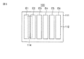
例えば、液体燃料を収納する液体燃料収納室と、前記液体燃料の気化成分をアノードに供給すための気液分離膜を有する気体供給型燃料電池においては、燃料電池100の単位セルの図5に示す位置に対応する位置に形成された燃料供給口114から液体燃料を気液分離膜に供給すると、図中の左側と中央側のアノード触媒層電極112(E1〜E6)の隣り合う位置から順番に気化された液体燃料と接触して発電するが、セル全体に燃料が十分に行き渡るまでの間において、図中の右側のアノード触媒層電極E3〜E6は未だ発電を開始していないか又は発電量が小さいので、燃料供給口114の位置から触媒層電極E1〜E6までの相対距離の相違によって発電動作にばらつきを生じる。
For example, in a gas supply type fuel cell having a liquid fuel storage chamber for storing liquid fuel and a gas-liquid separation membrane for supplying a vaporized component of the liquid fuel to the anode, FIG. When liquid fuel is supplied to the gas-liquid separation membrane from the
また、燃料電池100を一旦停止した後に運転を再開する場合に、各アノード触媒層電極E1〜E6に残っている燃料の残量がばらばらであるので、各セルの発電動作の立ち上がりにずれを生じ、所望の発電性能を得ることができない。
In addition, when the operation is resumed after the
本発明は上記課題を解決するためになされたものであり、セル間の発電動作にばらつきを生じることなく、良好な発電性能を有する燃料電池を提供することを目的とする。 The present invention has been made to solve the above-described problems, and an object of the present invention is to provide a fuel cell having good power generation performance without causing variations in power generation operation between cells.
本発明に係る燃料電池は、電解質膜と、該電解質膜を間に挟んで対向配置されたアノードとカソードを単位セルとして備え、複数の単位セルを直列に接続し、前記複数の単位セルのアノード側に配置された液体燃料を収容する液体燃料収容室と、前記アノードと前記液体燃料収容室の間に配置され前記液体燃料の気化成分をアノードに供給するための気液分離膜を有する燃料電池であって、前記アノード及びカソードの各触媒層電極として実質的に同一の平面上に並列に配置され、所定のアスペクト比を有する形状の複数の触媒層電極と、前記気液分離膜の前記液体燃料収容室側に積層された液体燃料含浸層と、前記液体燃料含浸層の液体燃料収容室側に積層され、前記アノード触媒層電極の実質的に同じ部位に対応した位置に形成された前記液体燃料含浸層へ液体燃料を供給する単数又は複数の燃料供給口が形成された液体燃料供給フレームと、を有することを特徴とする。 A fuel cell according to the present invention includes an electrolyte membrane, an anode and a cathode that are arranged to face each other with the electrolyte membrane interposed therebetween as a unit cell, and a plurality of unit cells are connected in series, and the anode of the plurality of unit cells A fuel cell having a liquid fuel storage chamber for storing liquid fuel disposed on the side, and a gas-liquid separation membrane disposed between the anode and the liquid fuel storage chamber for supplying a vaporized component of the liquid fuel to the anode A plurality of catalyst layer electrodes arranged in parallel on the same plane as the catalyst layer electrodes of the anode and the cathode and having a predetermined aspect ratio, and the liquid of the gas-liquid separation membrane A liquid fuel impregnated layer stacked on the fuel storage chamber side, and a liquid fuel impregnated layer stacked on the liquid fuel storage chamber side of the liquid fuel impregnated layer, before being formed at a position corresponding to substantially the same part of the anode catalyst layer electrode A liquid fuel supply frame for supplying a liquid fuel (s) of the fuel supply port is formed to the liquid fuel-impregnated layer, and having a.
この場合に、触媒層電極の長手方向の一端部が他端部よりも相対的に高いところに位置し、前記液体燃料供給フレームの前記触媒層電極の長手方向の一端部に近接して対応する位置に前記燃料供給口が配置され、発電時に前記燃料供給口と前記触媒層電極との相対的な位置関係を実質的に変えない据え置き型であることが好ましい。パッシブ型の燃料電池では、燃料供給の駆動力として毛細管現象ばかりでなく重力も利用されるので、発電時における燃料電池搭載機器の姿勢が発電性能に重大な影響を及ぼすおそれがある。そこで、触媒層電極を含むMEAを長手方向に傾けて配置し、触媒層電極の長手方向の一端部が他端部よりも高いところに位置させ、液体燃料供給フレームの燃料供給口を電極長手方向一端部に近接させる位置に形成し、液体燃料を気液分離膜に積層された液体燃料含浸層に供給することにより、高い位置の燃料供給口から燃料を供給することで気液分離膜から気化した液体燃料は、複数の触媒層電極を含むMEAにわたって燃料を円滑に均一に分散させることができる。 In this case, one end portion of the catalyst layer electrode in the longitudinal direction is positioned higher than the other end portion, and corresponds to the one end portion of the liquid fuel supply frame in the longitudinal direction of the catalyst layer electrode. Preferably, the fuel supply port is disposed at a position, and is a stationary type that does not substantially change the relative positional relationship between the fuel supply port and the catalyst layer electrode during power generation. In passive type fuel cells, not only capillarity but also gravity is used as the driving force for fuel supply, so the posture of the fuel cell-equipped device during power generation may have a significant effect on power generation performance. Therefore, the MEA including the catalyst layer electrode is disposed to be inclined in the longitudinal direction, and one end portion in the longitudinal direction of the catalyst layer electrode is positioned higher than the other end portion, and the fuel supply port of the liquid fuel supply frame is disposed in the electrode longitudinal direction. Vaporized from the gas-liquid separation membrane by supplying fuel from the fuel supply port at a higher position by supplying liquid fuel to the liquid fuel-impregnated layer stacked on the gas-liquid separation membrane. The liquid fuel can smoothly and uniformly disperse the fuel over the MEA including the plurality of catalyst layer electrodes.
また、複数の触媒層電極は、所定の間隔をおいて隣り合って配列され、実質的に同一線上に揃って並ぶ長手方向端部を有するものとすることができる。このようにすると燃料供給口に対する触媒層電極の相対的な位置関係が一定になり、燃料の拡散が均等化される。ちなみに、触媒層電極内にはカーボン等の微粒子の二次粒子間または三次粒子間に形成される微小な細孔からなる空隙部が多数存在している。これらの空隙部は触媒層電極内における反応ガスの拡散経路として機能するものであり、良好な発電性能を得るためには、燃料は可能な限り触媒層電極の全体に均等に拡散していくことが望ましい。また、各セル間に生じる発電量のばらつきを抑えるためには、触媒層電極の各々に対応した位置に液体燃料供給フレームの燃料供給口が形成され、液体燃料含浸層へ各触媒層電極に対応した位置へ燃料が均等に供給されることが望まれる。 In addition, the plurality of catalyst layer electrodes may be arranged adjacent to each other at a predetermined interval, and may have longitudinal ends that are substantially aligned on the same line. In this way, the relative positional relationship of the catalyst layer electrode with respect to the fuel supply port becomes constant, and fuel diffusion is equalized. Incidentally, in the catalyst layer electrode, there are a large number of voids composed of fine pores formed between secondary particles or tertiary particles of fine particles such as carbon. These voids function as a reaction gas diffusion path in the catalyst layer electrode, and in order to obtain good power generation performance, the fuel should diffuse evenly throughout the catalyst layer electrode as much as possible. Is desirable. In addition, in order to suppress variations in the amount of power generated between cells, a fuel supply port of the liquid fuel supply frame is formed at a position corresponding to each of the catalyst layer electrodes, and each catalyst layer electrode corresponds to the liquid fuel impregnated layer. It is desirable that fuel be supplied evenly to the specified position.
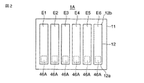
具体的には、複数の触媒層電極に1対1に対応する複数の燃料供給口を各触媒層電極の一方の端部近傍に対応する位置に配置(図2の46A参照)、あるいは複数の触媒層電極に対応する1個の燃料供給口を各触媒層電極の一方の端部近傍に対応する位置に配置(図3の46C参照)することができる。各燃料供給口が各触媒層に対応する位置に配置することにより、各触媒層電極に対して燃料が均等に供給される。 Specifically, a plurality of fuel supply ports corresponding to the plurality of catalyst layer electrodes are arranged at positions corresponding to the vicinity of one end of each catalyst layer electrode (see 46A in FIG. 2), or One fuel supply port corresponding to the catalyst layer electrode can be arranged at a position corresponding to the vicinity of one end of each catalyst layer electrode (see 46C in FIG. 3). By disposing each fuel supply port at a position corresponding to each catalyst layer, fuel is evenly supplied to each catalyst layer electrode.
また、燃料供給口が触媒層電極の長手方向の一端部または中央部に近接して対応する位置に配置させることができる(図3の46B参照)。燃料供給口を触媒層電極長手方向中央部に近接して対応する位置に配置すると、触媒層電極の長手方向端部に燃料が十分到達するまでの時間が短縮される。 Further, the fuel supply port can be disposed at a corresponding position in the vicinity of one end or the center in the longitudinal direction of the catalyst layer electrode (see 46B in FIG. 3). If the fuel supply port is disposed at a corresponding position close to the central portion in the longitudinal direction of the catalyst layer electrode, the time until the fuel reaches the longitudinal end portion of the catalyst layer electrode is shortened.
また、複数の触媒層電極に1対1に対応する実質的に同径の複数の燃料供給口を有することができる(図4の46D参照)。各燃料供給口を同径とすることにより、各触媒層電極に対して燃料が均等に供給される。 Further, the plurality of catalyst layer electrodes can have a plurality of fuel supply ports having substantially the same diameter corresponding to one-to-one (see 46D in FIG. 4). By making each fuel supply port have the same diameter, fuel is uniformly supplied to each catalyst layer electrode.
なお、図2〜4においては、触媒層電極と液体燃料供給口との位置関係が理解しやすいように便宜上、触媒層電極と液体燃料供給口との構成のみで、一見すると触媒層電極に接するよう液体燃料供給口が形成されているように記載しているが、実際には図1に示すようにその間には少なくとも気液分離膜および液体燃料含浸層を有している。 2 to 4, for the sake of convenience, only the configuration of the catalyst layer electrode and the liquid fuel supply port is in contact with the catalyst layer electrode at first glance so that the positional relationship between the catalyst layer electrode and the liquid fuel supply port can be easily understood. Although the liquid fuel supply port is described as being formed, actually, at least a gas-liquid separation membrane and a liquid fuel impregnation layer are provided between them as shown in FIG.
なお、触媒層電極の二次元平面視野内でのアスペクト比は、例えば1〜16倍の範囲とすることが好ましく、3〜8倍の範囲とすることが最も好ましい。アスペクト比が1倍を下回る場合は、電極の形状が横長となるため、燃料供給口から次の燃料供給口までの相互間隔が大きくなりすぎて、設計上の観点から言って好ましいものではなく、電池本体が大型化しやすくなるからである、
一方、触媒層電極のアスペクト比が16倍を超えると、燃料供給口を電極の長手中央に配置したとしても、電極の長手方向の両端まで十分な量の燃料が短時間で迅速に行き渡り難くなり、単位セル間での発電量のばらつきが解消されず、全体として発電効率が低下するからである。特に良好な発電効率を得るためには、触媒層電極のアスペクト比を3倍以上8倍以下の範囲とする。
The aspect ratio of the catalyst layer electrode in the two-dimensional plane view is preferably in the range of 1 to 16 times, and most preferably in the range of 3 to 8 times. When the aspect ratio is less than 1 time, the shape of the electrode is horizontally long, so the mutual distance from the fuel supply port to the next fuel supply port becomes too large, which is not preferable from the viewpoint of design. This is because the battery body is likely to be upsized.
On the other hand, when the aspect ratio of the catalyst layer electrode exceeds 16 times, even if the fuel supply port is arranged at the longitudinal center of the electrode, a sufficient amount of fuel is difficult to quickly and quickly reach both ends in the longitudinal direction of the electrode. This is because the variation in the amount of power generation between unit cells is not eliminated, and the power generation efficiency as a whole decreases. In order to obtain particularly good power generation efficiency, the aspect ratio of the catalyst layer electrode is set in the range of 3 to 8 times.
燃料供給口を規定する周壁材料として、例えばポリエーテルエーテルケトン(PEEK:ヴィクトレックス ピーエルシー社の商標)、ポリフェニレンサルファイド(PPS)、ポリテトラフルオロエチレン(PTFE)などの液体燃料で膨潤等を生じにくい硬質の樹脂を用いることが望ましいが、耐食性に優れたコーティングを施せばステンレス鋼やニッケル金属などの耐食性に優れた金属材料を用いることもできる。 For example, polyether ether ketone (PEEK: trademark of Victorex PLC), polyphenylene sulfide (PPS), polytetrafluoroethylene (PTFE), and the like as a peripheral wall material that defines the fuel supply port hardly cause swelling. It is desirable to use a hard resin, but if a coating having excellent corrosion resistance is applied, a metal material having excellent corrosion resistance such as stainless steel and nickel metal can be used.
燃料には、メタノール水溶液や純メタノール、エタノール水溶液や純エタノール、ジメチルエーテル、ギ酸、水素化ホウ素ナトリウム水溶液、水素化ホウ素カリウム水溶液、水素化リチウム水溶液などを用いることができる。また、燃料は濃度100%から数%までの範囲で種々の濃度のものを用いることができる。いずれにしても、燃料電池に応じた液体燃料が収容される。 As the fuel, methanol aqueous solution, pure methanol, ethanol aqueous solution, pure ethanol, dimethyl ether, formic acid, sodium borohydride aqueous solution, potassium borohydride aqueous solution, lithium hydride aqueous solution and the like can be used. Further, fuels having various concentrations in a range from 100% to several percent can be used. In any case, liquid fuel corresponding to the fuel cell is accommodated.
本発明によれば、良好な電池性能が安定して得られるようになり、ノートパソコン、携帯電話、携帯オーディオ、携帯ゲーム機などのコードレス携帯機器などの電源としてバラツキの少ない出力特性を得ることができる。 According to the present invention, good battery performance can be stably obtained, and output characteristics with less variation can be obtained as a power source for cordless portable devices such as notebook computers, mobile phones, portable audio devices, and portable game machines. it can.
以下、添付の図面を参照して本発明を実施するための最良の形態を説明する。 The best mode for carrying out the present invention will be described below with reference to the accompanying drawings.
(第1の実施の形態)
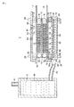
先ず、燃料電池の全体概要について図1を参照して説明する。燃料電池1は、全体が燃料タンク10、保護カバー20等で覆われ、内部に複数の単位セルを有するものである。燃料電池1は、燃料タンク10、保護カバー20側からシール部材18,を介して内部の単位セルをボルト28とナット29で締め付けて一体化した1つのユニットとして構成されている。燃料電池1の内部には、押え部材としてのシール部材18,及びスペーサ19,35によって種々のスペースや間隙が形成されている。それらのスペースや間隙のうち、例えばアノード側のスペースは液体燃料収容室32および気化室36として用いられ、カソード側のスペースは空気透過層26であり、外気の空気の通過を阻害せず、外部からの微笑の埃や異物の混入、さらには接触などを防止するためのものである。この空気透過層26としては、好ましくは気孔率が例えば20〜60%の多孔性フィルムなどが用いられる。
(First embodiment)
First, an overall outline of the fuel cell will be described with reference to FIG. The
アノードガス拡散層15から負極リード13に電子を取り出して、発電エネルギーの効率良い利用を可能とするために、負極リード13の反対面側にスペーサ35を取り付け、気化室36を規定している。この気化室36は液体燃料収容室32に隣接して設けられ、両者32,36間は気液分離膜34により仕切られている。気液分離膜34は、多数の細孔を有するポリテトラフルオロエチレン(PTFE)シートからなり、液体燃料(メタノール液又はその水溶液)を遮断し、燃料ガス(メタノールガス)を透過させるものである。
In order to take out electrons from the anode
そして、気液分離膜34の液体燃料収容室32側に積層された液体燃料含浸層45と、液体燃料含浸層45の液体燃料収容室側32に積層され、アノード触媒層電極15の実質的に同じ部位に対応した位置に形成された液体燃料含浸層45へ液体燃料を供給する燃料供給口46が形成された液体燃料供給フレーム44を有している。
Then, the liquid
なお、アノード側には図示しない排気流路が設けられ、該排気流路を通って副生物であるCO2ガスが反応系外に排出されるようになっている。また、負極リード13は多くの開口と間隙を有し、燃料成分ガスや副生ガス(CO2)の拡散を阻害しない形状とすることが望ましい。
An exhaust channel (not shown) is provided on the anode side, and CO 2 gas as a by-product is discharged out of the reaction system through the exhaust channel. Further, it is desirable that the
液体燃料収容室32は、保護カバー10および液体燃料供給フレーム44によって周囲を規定される所定容量のスペースからなり、このスペースの適所(例えば燃料タンク10の側面)において液受入口31aが開口している。液受入口31aには例えばバイオネット式のカプラー31が取り付けられ、燃料を補給するときを除いて、カプラー31により燃料供給口31aが閉鎖されている。この燃料電池本体側のカプラー31は外部カートリッジ側のカプラー43が液密に係合され得るような形状に形成されている。例えばカートリッジ側のカプラー43の溝を燃料電池本体側のカプラー31の突起に係合させて案内しながら、カプラー43をカプラー31のなかに押し込むと、カプラーの内蔵バルブが開いてカートリッジ側の流路が燃料電池本体側の流路に連通し、カートリッジ40の内圧によって液体燃料2が輸送チューブ42を通って液受入口31aから液体燃料収容室32内に流入するようになっている。
The liquid
気化室36は、スペーサ35と気液分離膜34によって周囲を規定されている。ボルトナット28,29の締め付けに耐えて変形しないように、スペーサ35の周縁部は断面コ字状に形成され、気化室36として所定幅のスペースが確保されている。
The periphery of the vaporizing
スペーサ35の上面において複数の気化燃料供給口14が開口している。これらの気化燃料供給口14は、負極リード13を貫通し、アノードガス拡散層15の側にそれぞれ連通している。液体燃料収容室32内の液体燃料2の一部がガス化すると、その燃料ガス成分は気液分離膜34を通って気化室34に入り、さらに気化室34から気化燃料供給口14を通ってアノードガス拡散層15の側に導入され、発電反応に寄与する。
A plurality of vaporized
燃料電池の単位セルは、電解質膜11、アノードおよびカソードを備えている。アノードとカソードは電解質膜11を間に挟んで対向配置されている。アノードはアノード触媒層電極12およびアノードガス拡散層15を有する。アノード触媒層電極12は、ガス拡散層15を介して供給される燃料を酸化して燃料から電子とプロトンとを取り出すものであり、触媒層電極12とガス拡散層15とが積み重ねられた積層構造をなしている。アノード触媒層電極12は、例えば、触媒を含む炭素粉末により構成されている。触媒には、例えば、白金(Pt)の微粒子、鉄(Fe)、ニッケル(Ni)、コバルト(Co)、ルテニウム(Ru)あるいはモリブデン(Mo)などの遷移金属あるいはその酸化物あるいはそれらの合金などの微粒子が用いられる。但し、触媒をルテニウムと白金との合金により構成するようにすれば、一酸化炭素(CO)の吸着による触媒の不活性化を防止することができるので好ましい。
The unit cell of the fuel cell includes an
また、アノード触媒層電極12は、後述する固体電解質膜11に用いられる樹脂の微粒子を含むほうがより望ましい。発生させたプロトンの移動を容易とするためである。アノードガス拡散層15は、例えば多孔質の炭素材料よりなる薄膜で構成され、具体的にはカーボンペーパーまたは炭素繊維などで構成されている。なお、アノードガス拡散層15の端部に導通する負極リード13が外方に延び出している。
The anode
図2に示すように、本実施の形態では、液体燃料供給フレーム44の燃料供給口46Aの各々は、アノードガス拡散層15の長手方向端部(短辺)の近傍に1対1に対応する位置にそれぞれ開口し、その形状は短辺の60%以上の幅を有するものであれば、その形状は適宜選択される。アノードガス拡散層15とアノード触媒層電極12とはサイズがほぼ同じであり、両者は全面にわたり密着するように重ねて熱プレス成形されるので、結局、燃料供給口46の各々はアノード触媒層電極12の長手方向端部(短辺)の近傍に1対1に対応する位置にそれぞれ開口することになる。なお、各アノード触媒層電極12はアスペクト比が3〜8(本実施例ではアスペクト比6)の細長い矩形状である。また、隣り合うアノード触媒層電極12の相互間隔は約1mmである。また、燃料供給口14の径は2〜5mm程度である。燃料供給口14の形状は丸穴のみに限定されるものではなく、長円、楕円、矩形、三角形、五角形以上の多角形など種々の形状とすることができる。
As shown in FIG. 2, in the present embodiment, each of the
カソードはカソード触媒層電極12およびカソードガス拡散層16を有する。カソード触媒層電極12は、酸素を還元して、電子とアノード触媒層電極12において発生したプロトンとを反応させて水を生成するものであり、例えば上述のアノード触媒層電極12及びガス拡散層15と同様に構成されている。すなわち、カソードは、固体電解質膜11の側から順に触媒を含む炭素粉末よりなるカソード触媒層電極12と多孔質の炭素材料よりなるカソードガス拡散層16(ガス透過層)とが積み重ねられた積層構造をなしている。カソード触媒層電極12に用いられる触媒はアノード触媒層電極12のそれと同様であり、アノード触媒層電極12が固体電解質膜11に用いられる樹脂の微粒子を含む場合があることもアノード触媒層電極12と同様である。なお、カソードガス拡散層16の端部に導通する正極リード17が外方に延び出している。また、カソード側の保護カバー20には複数の細かな通気孔24が形成され、空気透過層26にそれぞれ連通している。
The cathode has a cathode
電解質膜11は、アノード触媒層電極12において発生したプロトンをカソード触媒層電極12に輸送するためのものであり、電子伝導性を持たず、プロトンを輸送することが可能な材料により構成されている。例えば、ポリパーフルオロスルホン酸系の樹脂膜、具体的には、デュポン社製のナフィオン膜、旭硝子社製のフレミオン膜、あるいは旭化成工業社製のアシプレックス膜などにより構成されている。なお、ポリパーフルオロスルホン酸系の樹脂膜以外にも、トリフルオロスチレン誘導体の共重合膜、リン酸を含浸させたポリベンズイミダゾール膜、芳香族ポリエーテルケトンスルホン酸膜、あるいは脂肪族炭化水素系樹脂獏などプロトンを輸送可能な電解質膜11を構成するようにしてもよい。
The
アノードガス拡散層15の電解質膜11と反対側には、例えば、内部に形成された液体燃料貯蔵空間を有する液体燃料収容室32が設けられている。高濃度な液体燃料を使用することで、燃料電池体積効率が向上するとともに、燃料電池と一緒に携帯される燃料カートリッジ40の大きさと重量が小さく抑えられるという利点がある。
On the opposite side of the anode
保護カバー10及びスペーサ35は、例えばポリエーテルエーテルケトン(PEEK:ヴィクトレックス ピーエルシー社の商標)、ポリフェニレンサルファイド(PPS)、ポリテトラフルオロエチレン(PTFE)、などの液体燃料で膨潤等を生じいくい硬質のプラスチックでつくることが望ましいが、耐食性に優れたコーティングを施せばステンレス鋼やニッケル金属などの耐食性に優れた金属材料でつくることもできる。燃料タンク10及びスペーサ35を金属材料とする場合は、同一電池容器内に配置されているそれぞれの負極同士が短絡しないように図示しない絶縁部材を負極相互間に挿入する必要がある。
The
液体燃料収容室32の内部には、気液分離膜34の液体燃料収容室32側に積層された液体燃料含浸層45を有している。液体燃料含浸層45として、例えば多孔質ポリエステル繊維、多孔質オレフィン系樹脂等多硬質繊維や、連続気泡多孔質体樹脂が好ましい。この液体燃料含浸層45は、気液分離膜34と燃料供給口46Aが形成された液体燃料供給フレームとの間に配置され、燃料タンク10内の液体燃料2が減少した場合や燃料電池本体が傾斜して載置され燃料供給が偏った場合においても、気液分離膜に均質に燃料供給され、その結果、アノード触媒層15に均質に気化された液体燃料を供給することが可能となる。ポリエステル繊維以外にも、アクリル酸系の樹脂などの各種吸水性ポリマーにより構成してもよく、スポンジまたは繊維の集合体など液体の浸透性を利用して液体を保持することができる材料により構成する。本液体燃料含浸部は,本体の姿勢に関わらず適量の燃料を供給するのに有効である。なお、液体燃料としては、例えばメタノール水溶液、純メタノール、エタノール水溶液、純エタノール、プロパノール水溶液、ギ酸水溶液、ギ酸ナトリウム水溶液、酢酸水溶液、エチレングリコール水溶液、ジメチルエーテルなどの水素を含む有機系の水溶液が用いられる。中でもメタノール水溶液は、炭素数が1で反応の際に発生するのが炭酸ガスであると共に、低温での発電反応が可能であり、産業廃棄物から比較的容易に製造することができるので好ましい。いずれにしても、燃料電池に応じた液体燃料が収容される。
Inside the liquid
カソード側の保護カバー20には、例えば間隙を介してカソードガス拡散層16に外気を自然拡散により供給するための多数の通気孔24が開口している。これらの通気孔24は、外気が通過する開口を形成するが、外気の通過を阻害せずに、外部からカソードガス拡散層16への微小あるいは針状の異物の浸入・接触を防止しうるような形状が工夫されている。
In the
本実施の形態では、燃料供給口46Aの各々をアノード触媒層電極12の長手方向端部(短辺)の近傍に1対1に対応する位置にそれぞれ開口させているので、各アノード触媒層電極12に供給される燃料の量が均等化され、起動時および再起動時において単位セル間に発電量のばらつきが発生しなくなる。
In the present embodiment, each of the
具体的には、図1に示した燃料電池評価セルを用い、アスペクト比1:5.8の6枚の触媒層電極12(E1〜E6)を1枚の電解質膜11上に並列に配置し、図2に示すような液体燃料供給口46Aが各アノード触媒層電極12の長手方向端部(短編)の1:1に対応する位置にそれぞれ開口した液体燃料供給フレーム44を配置した。液体燃料収容室32に純度99.9重量%のメタノールを10ml供給した。その後、各セルの起動時の電圧と発電時の2.1V定電圧測定を行った。
Specifically, using the fuel cell evaluation cell shown in FIG. 1, six catalyst layer electrodes 12 (E1 to E6) having an aspect ratio of 1: 5.8 are arranged in parallel on one
また、比較として、上記第1の実施の形態と同様の単位セルを用い、液体燃料供給口を図5に示す液体燃料供給口114のように左端および左端から2番目のアノード触媒層電極112(E1〜E6)の間に配置した。その後、各セルの起動時の電圧と発電時の2.1V定電圧測定を行った。 それらの結果を左端の単位セルの電圧を100とした場合の電圧比率(%)として各アノード触媒層電極E1〜E6に対応するセルの電圧を図6に示す。図中の特性線A1は実施例1の起動時のセル電圧特性、特性線B1は実施例1の定電圧測定時(定常発電時)のセル電圧特性、特性線Cは比較例の起動時のセル電圧特性、特性線Dは比較例の定電圧測定時(定常発電時)のセル電圧特性をそれぞれ示す。図6から明らかなように、本実施の形態のおける燃料電池では、各セルの電圧のばらつきも起動時および発電時における電圧ばらつきも±2%以内に抑えることが可能となり、単位セル間の発電量のばらつきは小さい。これに対して、比較例の燃料電池では、液体燃料供給口から離れるに従い単位セルの電圧が低下しており、起動時および発電時のいずれにおいても均一な燃料供給が行われておらず、各単位セル間の発電量のばらつきが大きくなっている。
For comparison, the same unit cell as in the first embodiment is used, and the liquid fuel supply port is the second anode catalyst layer electrode 112 (from the left end and the second end from the left end, like the liquid
(第2の実施の形態)
図3を用いて第2の実施の形態について説明する。なお、本実施の形態が上記第1の実施の形態と重複する部分の説明は省略する。
(Second Embodiment)
A second embodiment will be described with reference to FIG. Note that description of portions in which the present embodiment overlaps with the first embodiment is omitted.
本実施形態では燃料電池1Aの燃料供給口として単一のスリットで形成された燃料供給口46Bあるいは46Cを採用している。燃料供給口46Bあるいは46Cはアノード触媒層電極12の長手にほぼ直交する向きに開口するものである。すなわち、燃料供給口46Bあるいは46Cからアノード触媒層電極12までの距離が実質的に等距離となるところに燃料供給口46Bあるいは46Cは位置している。燃料供給口46Bあるいは46Cの幅は触媒層電極の長辺に対して0.5〜10%の範囲の幅であることが好ましく、さらには1〜5%の範囲の幅にすることが好ましい。
In the present embodiment, a
燃料供給口46Bあるいは46Cは、アノード触媒層電極12の長手方向一方側端部(一方側の短辺)12aの近傍に開口(46C)させてもよいし、あるいはアノード触媒層電極12の長手方向中央部に開口(46B)させてもよい。後者の例では、燃料供給口46Bから供給される燃料は、アノード触媒層電極12の長手方向中央部から長手方向両端部12a,12bに向けて流れるので、その拡散時間が前者の例に比べて半分程度になり、アノード触媒層電極12の全体にわたり燃料を迅速に拡散させることができる。
The
具体的には、図1に示した燃料電池評価セルを用い、アスペクト比1:5.8の6枚の触媒層電極12(E1〜E6)を1枚の電解質膜11上に並列に配置し、図3に示すような液体燃料供給口46Cが各アノード触媒層電極12の長手方向端部(短編)に対応する位置にスリット状に開口した液体燃料供給フレーム44を配置した。液体燃料収容室32に純度99.9重量%のメタノールを10ml供給した。その後、各セルの起動時の電圧と2.1V低電圧測定を行った。
Specifically, using the fuel cell evaluation cell shown in FIG. 1, six catalyst layer electrodes 12 (E1 to E6) having an aspect ratio of 1: 5.8 are arranged in parallel on one
その結果および第1の実施形態で用いた燃料電池の測定結果と共に、左端の単位セルの電圧を100とした場合の電圧比率(%)として各セルの電圧を図7に示す。図中の特性線A2は実施例2の起動時のセル電圧特性、特性線B2は実施例2の定電圧測定時(定常発電時)のセル電圧特性、、特性線Cは比較例の起動時のセル電圧特性、特性線Dは比較例の定電圧測定時(定常発電時)のセル電圧特性をそれぞれ示す。図7から明らかなように、本実施の形態のおける燃料電池では、各セルの電圧のばらつきも起動時および発電時における電圧ばらつきも±2%以内に抑えることが可能となり、単位セル間の発電量のばらつきは小さい。これに対して、比較例の燃料電池では、液体燃料供給口から離れるに従い単位セルの電圧が低下しており、起動時および発電時のいずれにおいても均一な燃料供給が行われておらず、各単位セル間の発電量のばらつきが大きくなっている。 (第3の実施の形態)
図4を用いて第3の実施の形態について説明する。なお、本実施の形態が上記第1及び第2の実施の形態と重複する部分の説明は省略する。
FIG. 7 shows the voltage of each cell as a voltage ratio (%) with the result and the measurement result of the fuel cell used in the first embodiment, where the voltage of the leftmost unit cell is 100. The characteristic line A2 in the figure is the cell voltage characteristic at the start of the second embodiment, the characteristic line B2 is the cell voltage characteristic at the constant voltage measurement (steady power generation) in the second embodiment, and the characteristic line C is the start of the comparative example. The cell voltage characteristics and characteristic line D show the cell voltage characteristics at the time of constant voltage measurement (during steady power generation) in the comparative example. As is clear from FIG. 7, in the fuel cell according to the present embodiment, it is possible to suppress the voltage variation of each cell and the voltage variation at start-up and power generation to within ± 2%. The amount of variation is small. On the other hand, in the fuel cell of the comparative example, the voltage of the unit cell decreases as the distance from the liquid fuel supply port increases, and uniform fuel supply is not performed at the time of start-up and power generation. The variation in power generation amount between unit cells is large. (Third embodiment)
A third embodiment will be described with reference to FIG. In addition, description of the part which this Embodiment overlaps with the said 1st and 2nd Embodiment is abbreviate | omitted.
本実施形態では燃料電池1Bが組み込まれる機器を実質的に姿勢を変えない据え置き型(例えばノートパソコン)としている。すなわち、据え置き型機器においては発電時に燃料供給口46Dと触媒層電極12との相対的な位置関係を実質的に変えない。アノード触媒層電極12の長手方向の一端部12aが他端部12bよりも相対的に高いところに配置し、かつ燃料供給口46Dを複数のアノード触媒層電極E1〜E6(12)の長手方向一方側端部(一方側の短辺)12aの近傍に開口させている。
In the present embodiment, a device in which the
パッシブ型の燃料電池では、燃料供給の駆動力として毛細管現象ばかりでなく重力も利用されるので、発電時における燃料電池搭載機器の姿勢が発電性能に重大な影響を及ぼすおそれがある。そこで、触媒層電極E1〜E6を含むMEAを長手方向に傾けて配置し、触媒層電極の長手方向の一端部12aを他端部12bよりも高いところに位置させ、燃料供給口46Dを電極長手方向一端部12aに近接させることにより、高い位置の燃料供給口46Dから燃料を供給し、触媒層電極E1〜E6を含むMEAの全体にわたって燃料を円滑に分散させることができる。これにより起動時または再起動時における単位セル間の発電量のばらつきが抑えられる。
In passive type fuel cells, not only capillarity but also gravity is used as the driving force for fuel supply, so the posture of the fuel cell-equipped device during power generation may have a significant effect on power generation performance. Therefore, the MEA including the catalyst layer electrodes E1 to E6 is arranged to be inclined in the longitudinal direction, the one
以上、種々の実施の形態を挙げて説明したが、本発明は上記各実施の形態のみに限定されるものではなく、種々変形および組み合わせることが可能である。 Although various embodiments have been described above, the present invention is not limited to the above embodiments, and various modifications and combinations can be made.
1,1A,1B,1C,100…燃料電池、
2…液体燃料(メタノール液)、
10…燃料タンク、
20…保護カバー(筐体外装板)、
11,111…固体電解質膜、
12,112,E1〜E6…触媒層電極、
12a,12b…電極端部、
13…負極リード(アノード集電体)、
14…気化燃料供給口、
15…アノードガス拡散層(アノードPTFE)、16…カソードガス拡散層、
17…正極リード(カソード集電体)、17a…水供給口、
18…Oリング(シール部材)、
19…押え部材(シール部材)、
24…通気孔、
26…空気透過層、
28…ボルト、29…ナット、
31…カプラー、
31a…液受入口、
32…液体燃料収容室、
34…気液分離膜、
35…スペーサ、
36…気化室、
40…燃料カートリッジ(外部タンク)、
41…導入口、
42…輸送チューブ、
43…カプラー、
44…液体燃料供給フレーム、
45…液体燃料含浸層
46,46A,46B,46C,114…燃料供給口。
1, 1A, 1B, 1C, 100 ... fuel cell,
2 ... Liquid fuel (methanol liquid),
10 ... Fuel tank,
20 ... Protective cover (housing exterior plate),
11, 111 ... solid electrolyte membrane,
12, 112, E1-E6 ... catalyst layer electrode,
12a, 12b ... electrode ends,
13 ... Negative electrode lead (anode current collector),
14 ... Vaporized fuel supply port,
15 ... anode gas diffusion layer (anode PTFE), 16 ... cathode gas diffusion layer,
17 ... Positive electrode lead (cathode current collector), 17a ... Water supply port,
18 ... O-ring (seal member),
19: Presser member (seal member),
24 ... vents,
26 ... an air permeable layer,
28 ... bolts, 29 ... nuts,
31 ... Coupler,
31a: Liquid inlet,
32 ... Liquid fuel storage chamber,
34 ... Gas-liquid separation membrane,
35 ... spacer,
36 ... Vaporization room,
40 ... Fuel cartridge (external tank),
41 ... Inlet,
42 ... transport tube,
43 ... Coupler,
44 ... Liquid fuel supply frame,
45 ... Liquid fuel impregnated
Claims (6)
前記アノード及びカソードの各触媒層電極として実質的に同一の平面上に並列に配置され、所定のアスペクト比を有する形状の複数の触媒層電極と、
前記気液分離膜の液体燃料収容室側に積層された液体燃料含浸層と、
前記液体燃料含浸層の液体燃料収容室側に積層され、前記アノード触媒層電極の実質的に同じ部位に対応した位置に形成された前記液体燃料含浸層へ液体燃料を供給する単数又は複数の燃料供給口が形成された液体燃料供給フレームと、
を有することを特徴とする燃料電池。 An electrolyte membrane, and an anode and a cathode arranged opposite to each other with the electrolyte membrane interposed therebetween as a unit cell, a plurality of unit cells connected in series, and a liquid fuel arranged on the anode side of the plurality of unit cells A fuel cell having a liquid fuel storage chamber, and a gas-liquid separation membrane disposed between the anode and the liquid fuel storage chamber for supplying a vaporized component of the liquid fuel to the anode,
A plurality of catalyst layer electrodes arranged in parallel on substantially the same plane as each of the anode and cathode catalyst layer electrodes, and having a predetermined aspect ratio;
A liquid fuel impregnated layer laminated on the liquid fuel storage chamber side of the gas-liquid separation membrane;
One or more fuels that are stacked on the liquid fuel storage chamber side of the liquid fuel impregnated layer and supply the liquid fuel to the liquid fuel impregnated layer formed at a position corresponding to substantially the same part of the anode catalyst layer electrode A liquid fuel supply frame formed with a supply port;
A fuel cell comprising:
Priority Applications (5)
| Application Number | Priority Date | Filing Date | Title |
|---|---|---|---|
| JP2005272543A JP2007087655A (en) | 2005-09-20 | 2005-09-20 | Fuel cell |
| US12/067,189 US20090047560A1 (en) | 2005-09-20 | 2006-09-14 | Fuel cell |
| PCT/JP2006/318256 WO2007034731A1 (en) | 2005-09-20 | 2006-09-14 | Fuel cell |
| CNA2006800340172A CN101263626A (en) | 2005-09-20 | 2006-09-14 | Fuel cell |
| TW095134635A TW200729597A (en) | 2005-09-20 | 2006-09-19 | Fuel cell |
Applications Claiming Priority (1)
| Application Number | Priority Date | Filing Date | Title |
|---|---|---|---|
| JP2005272543A JP2007087655A (en) | 2005-09-20 | 2005-09-20 | Fuel cell |
Publications (2)
| Publication Number | Publication Date |
|---|---|
| JP2007087655A true JP2007087655A (en) | 2007-04-05 |
| JP2007087655A5 JP2007087655A5 (en) | 2008-10-16 |
Family
ID=37888776
Family Applications (1)
| Application Number | Title | Priority Date | Filing Date |
|---|---|---|---|
| JP2005272543A Abandoned JP2007087655A (en) | 2005-09-20 | 2005-09-20 | Fuel cell |
Country Status (5)
| Country | Link |
|---|---|
| US (1) | US20090047560A1 (en) |
| JP (1) | JP2007087655A (en) |
| CN (1) | CN101263626A (en) |
| TW (1) | TW200729597A (en) |
| WO (1) | WO2007034731A1 (en) |
Cited By (4)
| Publication number | Priority date | Publication date | Assignee | Title |
|---|---|---|---|---|
| JP2008243491A (en) * | 2007-03-26 | 2008-10-09 | Toshiba Corp | Fuel cell |
| WO2008143020A1 (en) * | 2007-05-14 | 2008-11-27 | Nec Corporation | Solid state polymer type fuel cell |
| JP2011054447A (en) * | 2009-09-02 | 2011-03-17 | Seiko Instruments Inc | Fuel cell |
| JP2011146224A (en) * | 2010-01-14 | 2011-07-28 | Sharp Corp | Fuel cell |
Families Citing this family (3)
| Publication number | Priority date | Publication date | Assignee | Title |
|---|---|---|---|---|
| JP2008210679A (en) * | 2007-02-27 | 2008-09-11 | Toshiba Corp | Fuel cell |
| JP7018010B2 (en) * | 2018-11-16 | 2022-02-09 | 本田技研工業株式会社 | Fuel cell system |
| CN109950594B (en) * | 2019-04-22 | 2020-06-09 | 哈尔滨工业大学 | Methanol fuel transportation and fuel cell power generation system driven by waste heat |
Family Cites Families (6)
| Publication number | Priority date | Publication date | Assignee | Title |
|---|---|---|---|---|
| US6447941B1 (en) * | 1998-09-30 | 2002-09-10 | Kabushiki Kaisha Toshiba | Fuel cell |
| JP4296625B2 (en) * | 1999-03-15 | 2009-07-15 | ソニー株式会社 | Power generation device |
| JP3765999B2 (en) * | 2000-06-30 | 2006-04-12 | 株式会社東芝 | Fuel cell |
| CN1572036B (en) * | 2002-02-14 | 2010-04-28 | 日立麦克赛尔株式会社 | Liquid fuel cell |
| JP2003317791A (en) * | 2002-04-24 | 2003-11-07 | Hitachi Maxell Ltd | Liquid fuel cell |
| US8349521B2 (en) * | 2004-07-21 | 2013-01-08 | Kabushiki Kaisha Toshiba | Membrane electrode assembly |
-
2005
- 2005-09-20 JP JP2005272543A patent/JP2007087655A/en not_active Abandoned
-
2006
- 2006-09-14 WO PCT/JP2006/318256 patent/WO2007034731A1/en active Application Filing
- 2006-09-14 US US12/067,189 patent/US20090047560A1/en not_active Abandoned
- 2006-09-14 CN CNA2006800340172A patent/CN101263626A/en active Pending
- 2006-09-19 TW TW095134635A patent/TW200729597A/en unknown
Cited By (5)
| Publication number | Priority date | Publication date | Assignee | Title |
|---|---|---|---|---|
| JP2008243491A (en) * | 2007-03-26 | 2008-10-09 | Toshiba Corp | Fuel cell |
| WO2008143020A1 (en) * | 2007-05-14 | 2008-11-27 | Nec Corporation | Solid state polymer type fuel cell |
| US8252482B2 (en) | 2007-05-14 | 2012-08-28 | Nec Corporation | Solid polymer fuel cell |
| JP2011054447A (en) * | 2009-09-02 | 2011-03-17 | Seiko Instruments Inc | Fuel cell |
| JP2011146224A (en) * | 2010-01-14 | 2011-07-28 | Sharp Corp | Fuel cell |
Also Published As
| Publication number | Publication date |
|---|---|
| TW200729597A (en) | 2007-08-01 |
| WO2007034731A1 (en) | 2007-03-29 |
| CN101263626A (en) | 2008-09-10 |
| US20090047560A1 (en) | 2009-02-19 |
Similar Documents
| Publication | Publication Date | Title |
|---|---|---|
| JP4296625B2 (en) | Power generation device | |
| JP4568053B2 (en) | Fuel cell | |
| JP2007087655A (en) | Fuel cell | |
| US20100099005A1 (en) | Vapor fed direct hydrocarbon alkaline fuel cells | |
| JPWO2008023634A1 (en) | Fuel cell | |
| JPWO2007139059A1 (en) | Fuel cell | |
| JP5127267B2 (en) | Fuel cell and fuel cell system | |
| JP5028860B2 (en) | Fuel cell | |
| US20100098985A1 (en) | Fuel cell and electronic device including the same | |
| JPWO2008068887A1 (en) | Fuel cell | |
| JPWO2008068886A1 (en) | Fuel cell | |
| JPWO2008102424A1 (en) | Fuel cell | |
| JP2008041401A (en) | Fuel cell | |
| JP2009021113A (en) | Fuel cell | |
| JP4403465B2 (en) | Power generation method | |
| JP2011096468A (en) | Fuel cell | |
| JP5272364B2 (en) | Fuel cell cartridge | |
| JPWO2008023633A1 (en) | Fuel cell | |
| JP2008218030A (en) | Fuel cell | |
| JP2008276988A (en) | Fuel cell | |
| JP2007335247A (en) | Electronic equipment provided with fuel cell | |
| JP2007335367A (en) | Fuel cell | |
| JPWO2008062551A1 (en) | Polymer electrolyte fuel cell | |
| JP2006269130A (en) | Fuel cell for portable equipment, and cartridge | |
| WO2011052650A1 (en) | Fuel cell |
Legal Events
| Date | Code | Title | Description |
|---|---|---|---|
| A521 | Request for written amendment filed |
Free format text: JAPANESE INTERMEDIATE CODE: A523 Effective date: 20080901 |
|
| A621 | Written request for application examination |
Free format text: JAPANESE INTERMEDIATE CODE: A621 Effective date: 20080901 |
|
| A762 | Written abandonment of application |
Free format text: JAPANESE INTERMEDIATE CODE: A762 Effective date: 20090615 |