JP2007081663A - Client server system - Google Patents
Client server system Download PDFInfo
- Publication number
- JP2007081663A JP2007081663A JP2005265400A JP2005265400A JP2007081663A JP 2007081663 A JP2007081663 A JP 2007081663A JP 2005265400 A JP2005265400 A JP 2005265400A JP 2005265400 A JP2005265400 A JP 2005265400A JP 2007081663 A JP2007081663 A JP 2007081663A
- Authority
- JP
- Japan
- Prior art keywords
- video data
- unit
- playback
- reproduction
- output
- Prior art date
- Legal status (The legal status is an assumption and is not a legal conclusion. Google has not performed a legal analysis and makes no representation as to the accuracy of the status listed.)
- Pending
Links
Images

Classifications
-
- H—ELECTRICITY
- H04—ELECTRIC COMMUNICATION TECHNIQUE
- H04N—PICTORIAL COMMUNICATION, e.g. TELEVISION
- H04N5/00—Details of television systems
- H04N5/76—Television signal recording
- H04N5/78—Television signal recording using magnetic recording
- H04N5/782—Television signal recording using magnetic recording on tape
- H04N5/783—Adaptations for reproducing at a rate different from the recording rate
-
- H—ELECTRICITY
- H04—ELECTRIC COMMUNICATION TECHNIQUE
- H04N—PICTORIAL COMMUNICATION, e.g. TELEVISION
- H04N21/00—Selective content distribution, e.g. interactive television or video on demand [VOD]
- H04N21/40—Client devices specifically adapted for the reception of or interaction with content, e.g. set-top-box [STB]; Operations thereof
- H04N21/41—Structure of client; Structure of client peripherals
- H04N21/4104—Peripherals receiving signals from specially adapted client devices
- H04N21/4126—The peripheral being portable, e.g. PDAs or mobile phones
- H04N21/41265—The peripheral being portable, e.g. PDAs or mobile phones having a remote control device for bidirectional communication between the remote control device and client device
-
- H—ELECTRICITY
- H04—ELECTRIC COMMUNICATION TECHNIQUE
- H04N—PICTORIAL COMMUNICATION, e.g. TELEVISION
- H04N21/00—Selective content distribution, e.g. interactive television or video on demand [VOD]
- H04N21/40—Client devices specifically adapted for the reception of or interaction with content, e.g. set-top-box [STB]; Operations thereof
- H04N21/41—Structure of client; Structure of client peripherals
- H04N21/426—Internal components of the client ; Characteristics thereof
- H04N21/42646—Internal components of the client ; Characteristics thereof for reading from or writing on a non-volatile solid state storage medium, e.g. DVD, CD-ROM
-
- H—ELECTRICITY
- H04—ELECTRIC COMMUNICATION TECHNIQUE
- H04N—PICTORIAL COMMUNICATION, e.g. TELEVISION
- H04N21/00—Selective content distribution, e.g. interactive television or video on demand [VOD]
- H04N21/40—Client devices specifically adapted for the reception of or interaction with content, e.g. set-top-box [STB]; Operations thereof
- H04N21/41—Structure of client; Structure of client peripherals
- H04N21/426—Internal components of the client ; Characteristics thereof
- H04N21/42661—Internal components of the client ; Characteristics thereof for reading from or writing on a magnetic storage medium, e.g. hard disk drive
-
- H—ELECTRICITY
- H04—ELECTRIC COMMUNICATION TECHNIQUE
- H04N—PICTORIAL COMMUNICATION, e.g. TELEVISION
- H04N21/00—Selective content distribution, e.g. interactive television or video on demand [VOD]
- H04N21/40—Client devices specifically adapted for the reception of or interaction with content, e.g. set-top-box [STB]; Operations thereof
- H04N21/43—Processing of content or additional data, e.g. demultiplexing additional data from a digital video stream; Elementary client operations, e.g. monitoring of home network or synchronising decoder's clock; Client middleware
- H04N21/436—Interfacing a local distribution network, e.g. communicating with another STB or one or more peripheral devices inside the home
- H04N21/4363—Adapting the video stream to a specific local network, e.g. a Bluetooth® network
- H04N21/43637—Adapting the video stream to a specific local network, e.g. a Bluetooth® network involving a wireless protocol, e.g. Bluetooth®, RF or wireless LAN [IEEE 802.11]
-
- H—ELECTRICITY
- H04—ELECTRIC COMMUNICATION TECHNIQUE
- H04N—PICTORIAL COMMUNICATION, e.g. TELEVISION
- H04N21/00—Selective content distribution, e.g. interactive television or video on demand [VOD]
- H04N21/60—Network structure or processes for video distribution between server and client or between remote clients; Control signalling between clients, server and network components; Transmission of management data between server and client, e.g. sending from server to client commands for recording incoming content stream; Communication details between server and client
- H04N21/65—Transmission of management data between client and server
- H04N21/658—Transmission by the client directed to the server
- H04N21/6587—Control parameters, e.g. trick play commands, viewpoint selection
-
- H—ELECTRICITY
- H04—ELECTRIC COMMUNICATION TECHNIQUE
- H04N—PICTORIAL COMMUNICATION, e.g. TELEVISION
- H04N5/00—Details of television systems
- H04N5/76—Television signal recording
- H04N5/765—Interface circuits between an apparatus for recording and another apparatus
- H04N5/775—Interface circuits between an apparatus for recording and another apparatus between a recording apparatus and a television receiver
-
- H—ELECTRICITY
- H04—ELECTRIC COMMUNICATION TECHNIQUE
- H04N—PICTORIAL COMMUNICATION, e.g. TELEVISION
- H04N5/00—Details of television systems
- H04N5/76—Television signal recording
- H04N5/78—Television signal recording using magnetic recording
- H04N5/781—Television signal recording using magnetic recording on disks or drums
-
- H—ELECTRICITY
- H04—ELECTRIC COMMUNICATION TECHNIQUE
- H04N—PICTORIAL COMMUNICATION, e.g. TELEVISION
- H04N5/00—Details of television systems
- H04N5/76—Television signal recording
- H04N5/84—Television signal recording using optical recording
- H04N5/85—Television signal recording using optical recording on discs or drums
Landscapes
- Engineering & Computer Science (AREA)
- Multimedia (AREA)
- Signal Processing (AREA)
- Computer Networks & Wireless Communication (AREA)
- Television Signal Processing For Recording (AREA)
- Two-Way Televisions, Distribution Of Moving Picture Or The Like (AREA)
- Signal Processing For Digital Recording And Reproducing (AREA)
Abstract
Description
本発明は、クライアント・サーバシステムに関する。 The present invention relates to a client / server system.
従来、サーバ装置が備えるAV機器(DVD(Digital Versatile Disc)/HDD(Hard Disk Drive)再生部等)により再生された映像データを、無線通信により、サーバ装
置からクライアント端末装置に伝送し、そして、クライアント端末装置が備える出力装置に出力することができるクライアント・サーバシステムが知られている。このようなクライアント・サーバシステムにおいては、無線通信により映像データを伝送するため、伝送遅延が生じるという問題がある。また、映像データは、伝送断絶や処理の都合上、クライアント端末装置に備えられたバッファに記憶されてから出力装置に出力される場合もあり、映像データが再生されてから出力されるまでに、更なるタイムラグが生じるという問題がある。
Conventionally, video data reproduced by an AV device (DVD (Digital Versatile Disc) / HDD (Hard Disk Drive) reproduction unit, etc.) provided in the server device is transmitted from the server device to the client terminal device by wireless communication, and 2. Description of the Related Art A client / server system that can output to an output device included in a client terminal device is known. In such a client / server system, there is a problem that transmission delay occurs because video data is transmitted by wireless communication. Also, the video data may be output to the output device after being stored in the buffer provided in the client terminal device for transmission interruption and processing, until the video data is reproduced and output, There is a problem that a further time lag occurs.
例えば、図7に示すように、AV機器で再生された映像データa,b,c,…は、クライアント端末装置に無線伝送されて、バッファに記憶され、その後、出力装置に出力される。 For example, as shown in FIG. 7, video data a, b, c,... Reproduced by an AV device are wirelessly transmitted to a client terminal device, stored in a buffer, and then output to an output device.
具体的には、例えば、時点[t13]においては、AV機器は映像データkを早送り再生モードで再生し、バッファは時点[t12]でAV機器により再生された映像データhを記憶し、出力装置は時点[t11]でAV機器により再生されて時点[t12]でバッファに記憶された映像データeを出力している。 Specifically, for example, at the time [t13], the AV device reproduces the video data k in the fast-forward playback mode, and the buffer stores the video data h reproduced by the AV device at the time [t12]. The video data e reproduced by the AV device at the time [t11] and stored in the buffer at the time [t12] is output.
AV機器による早送り再生モードでの再生動作中の時点[t13]において、ユーザにより操作されたサーバ装置用のリモートコントローラ(以下、「リモコン」という。)から、AV機器による再生モードとして通常再生モードを選択する旨の信号が送信されたとする。すなわち、ユーザは、映像データeの後に続く映像データ(映像データf以降の映像データ)に基づく映像を、通常再生モードで視聴したかったとする。リモコンから送信された信号を受信したサーバ装置は、AV機器を制御して、再生モードを、早送り再生モードから通常再生モードに切り替えさせる。すなわち、AV機器は、時点[t13]の直後から、再生モードを通常再生モードに切り替えるため、映像データl以降の映像データを通常再生モードで再生することとなり、ユーザ所望の映像データ(映像データf以降の映像データ)を、ユーザ所望の再生モード(通常再生モード)で再生することができないという問題がある。 At a time point [t13] during the playback operation in the fast-forward playback mode by the AV device, a normal playback mode is set as a playback mode by the AV device from a remote controller for the server device operated by the user (hereinafter referred to as “remote control”). Assume that a signal indicating selection is transmitted. That is, it is assumed that the user wants to view the video based on the video data following the video data e (video data after the video data f) in the normal playback mode. The server device that has received the signal transmitted from the remote control controls the AV device to switch the playback mode from the fast-forward playback mode to the normal playback mode. That is, since the AV device switches the playback mode to the normal playback mode immediately after the time [t13], the video data after the video data l is played back in the normal playback mode, and the user-desired video data (video data f There is a problem that subsequent video data) cannot be reproduced in a user-desired reproduction mode (normal reproduction mode).
そこで、例えば、映像データに時刻情報を付加する方法が提案された(例えば、特許文献1参照)。 Thus, for example, a method for adding time information to video data has been proposed (see, for example, Patent Document 1).
具体的には、例えば、サーバ装置(動画像伝送装置)においてAV機器(映像再生手段)により再生された映像データに時刻情報(カウンタ値など)を付加して、クライアント端末装置(映像受信手段)に伝送する。そして、ユーザにより、クライアント端末装置用のリモコンが操作されて、映像データの再生モードを切り替えるよう指示されると、クライアント端末装置は、当該指示の時点で出力装置(映像表示手段)により出力されていた映像データから時刻情報を取得してサーバ装置に伝送する。そして、サーバ装置は、当該時刻情報に基づいて映像データの戻し量を算出し、AV機器に、当該戻し量に対応する地点から映像データを再生させる。 Specifically, for example, time information (counter value or the like) is added to video data reproduced by an AV device (video reproduction means) in a server apparatus (moving image transmission apparatus), and a client terminal apparatus (video reception means). Transmit to. When the user operates the remote control for the client terminal device to instruct to switch the video data playback mode, the client terminal device is output by the output device (video display means) at the time of the instruction. Time information is acquired from the received video data and transmitted to the server device. Then, the server device calculates the return amount of the video data based on the time information, and causes the AV device to reproduce the video data from the point corresponding to the return amount.
さらに、例えば、出力装置に表示されたスライダーを操作して映像データの再生開始位置を指定する場合において、映像データにスライダーのつまみの移動量を対応付ける方法が提案された(例えば、特許文献2参照)。 Furthermore, for example, when the playback start position of the video data is designated by operating the slider displayed on the output device, a method for associating the moving amount of the slider knob with the video data has been proposed (see, for example, Patent Document 2). ).
具体的には、例えば、サーバ装置(映像送信機)に、映像データよりもデータが小さい当該映像データの静止画像データと、スライダーのつまみの移動量と、を対応付けて記憶しておく。そして、ユーザが、出力装置(画像音声出力部)に表示されたスライダーのつまみを移動させて、映像データの再生開始位置を指定すると、クライアント端末装置(映像受信機)は、当該つまみの移動量をサーバ装置に伝送する。そして、サーバ装置は、記憶しておいた静止画像データの中から、当該伝送されたつまみの移動量に対応する静止画像データを取得してクライアント端末装置に伝送すると共に、当該静止画像データに対応する位置から映像データの再生を開始する。 Specifically, for example, the still image data of the video data whose data is smaller than the video data and the movement amount of the slider knob are stored in association with each other in the server device (video transmitter). When the user moves the slider knob displayed on the output device (image / audio output unit) and designates the playback start position of the video data, the client terminal device (video receiver) moves the knob. Is transmitted to the server device. Then, the server device acquires still image data corresponding to the transmitted amount of movement of the knob from the stored still image data, transmits the still image data to the client terminal device, and supports the still image data. Playback of the video data starts from the position where it is to be performed.
また、例えば、一時停止が指示された場合において、出力装置に静止画像を出力させる方法も提案されている(例えば、特許文献3参照)。 Further, for example, a method for causing the output device to output a still image when a pause is instructed has been proposed (see, for example, Patent Document 3).
具体的には、例えば、ユーザにより、クライアント端末装置(受信ユニット)用のリモコンが操作されて、出力装置(液晶モニタ)により出力される映像データに基づく映像を一時停止(ポーズ)するよう指示されると、クライアント端末装置は、当該指示をサーバ装置(送信ユニット)に伝送すると共に、出力装置に当該指示の時点で出力されていた映像データに基づく静止画像を出力させる。 Specifically, for example, the user operates the remote control for the client terminal device (reception unit) to instruct to pause (pause) the video based on the video data output from the output device (liquid crystal monitor). Then, the client terminal device transmits the instruction to the server device (transmission unit) and causes the output device to output a still image based on the video data output at the time of the instruction.
また、無線通信による伝送遅延でなく、AV機器(圧縮映像再生装置)による、早送りや巻戻しをした後における圧縮映像データ再生の際の遅延を解決する方法も提案されている(例えば、特許文献4参照)。
しかしながら、例えば、特許文献1の方法のように、映像データに時刻情報を付加するには、映像データにMPEG符号化処理を施す必要がある。すなわち、特許文献1の方法は、映像データがMPEG符号化されて伝送される場合にのみ有効である。
However, for example, in order to add time information to video data as in the method of
また、特許文献2の方法は、スライダーによって、映像データの再生開始位置を指定する場合にのみ有効である。 Further, the method of Patent Document 2 is effective only when the playback start position of video data is specified by a slider.
さらに、例えば、特許文献3の方法は、一時停止指示をする場合にのみ有効である。 Furthermore, for example, the method of Patent Document 3 is effective only when a temporary stop instruction is given.
また、例えば、特許文献4の方法は、無線通信により映像データを伝送しない場合にのみ有効である。 For example, the method of Patent Document 4 is effective only when video data is not transmitted by wireless communication.
したがって、特許文献1〜4に開示されたどの方法も限られた場合にしか有効でなく、その使用が制限される。
Therefore, any method disclosed in
本発明の課題は、クライアント・サーバシステムにおける映像データの伝送の際に生じる遅延によるユーザ視聴の不具合防止をより汎用的に達成することができるクライアント・サーバシステムを提供することにある。 An object of the present invention is to provide a client / server system that can more generally achieve prevention of user viewing problems due to a delay that occurs during transmission of video data in the client / server system.
上記課題を解決するために、請求項1に記載の発明は、蓄積された映像データを、通常再生モード、早送り再生モード及び早戻り再生モードを含む所定の再生モードで再生する再生手段と、前記再生手段により再生された映像データを送信する送信手段と、を有するサーバ装置と、前記サーバ装置に無線ネットワークを介して接続され、前記送信手段により送信された映像データを受信する受信手段と、前記受信手段により受信された映像データを逐次記憶する記憶手段と、前記記憶手段に記憶された映像データを表示部に出力させる出力制御手段と、を有するクライアント端末装置と、を備えたクライアント・サーバシ
ステムにおいて、前記再生手段による再生モードを選択する選択手段と、前記再生手段により再生された映像データが、前記出力制御手段により前記表示部に出力されるまでのタイムラグを設定する設定手段と、前記再生手段による第1の再生モードでの再生動作中に、前記選択手段により第2の再生モードが選択された際に、映像データの再生位置を、前記設定手段により設定されたタイムラグ分に相当する前記第1の再生モードにおける再生位置まで移動させる処理を行う制御手段と、を備え、前記設定手段は、前記表示部に設定画面を表示させる設定画面表示制御手段と、前記設定画面に表示された入力欄に前記タイムラグを入力するための入力手段と、を備えることを特徴とする。
In order to solve the above-mentioned problem, the invention described in
請求項2に記載の発明は、蓄積された映像データを、通常再生モード、早送り再生モード及び早戻り再生モードを含む所定の再生モードで再生する再生手段と、前記再生手段により再生された映像データを送信する送信手段と、を有するサーバ装置と、前記サーバ装置に無線ネットワークを介して接続され、前記送信手段により送信された映像データを受信する受信手段と、前記受信手段により受信された映像データを逐次記憶する記憶手段と、前記記憶手段に記憶された映像データを表示部に出力させる出力制御手段と、を有するクライアント端末装置と、を備えたクライアント・サーバシステムにおいて、前記再生手段による再生モードを選択する選択手段と、前記再生手段により再生された映像データが、前記出力制御手段により前記表示部に出力されるまでのタイムラグを設定する設定手段と、前記再生手段による第1の再生モードでの再生動作中に、前記選択手段により第2の再生モードが選択された際に、映像データの再生位置を、前記設定手段により設定されたタイムラグ分に相当する前記第1の再生モードにおける再生位置まで移動させる処理を行う制御手段と、を備え、前記設定手段は、前記タイムラグを計測する計測手段を備え、前記計測手段は、前記クライアント端末装置側に備えられ、前記出力制御手段により出力される映像データを外部出力する外部出力部と、前記サーバ装置側に備えられ、前記外部出力部により出力される映像データを入力する外部入力部と、前記外部出力部と前記外部入力部とを接続する通信手段と、を備え、前記再生手段により再生された映像データが前記通信手段を介して前記外部入力部に入力されるまでの時間を、前記タイムラグとして計測することを特徴とする。 The invention according to claim 2 is a reproduction means for reproducing the stored video data in a predetermined reproduction mode including a normal reproduction mode, a fast forward reproduction mode and a fast return reproduction mode, and the video data reproduced by the reproduction means. A transmission device that transmits the video data transmitted from the transmission device, and the video data received by the reception device. In a client / server system comprising: a storage unit that sequentially stores a storage unit; and an output control unit that outputs video data stored in the storage unit to a display unit. Selection means for selecting the video data reproduced by the reproduction means, the output control means Setting means for setting a time lag until output to the display unit, and video data when the second reproduction mode is selected by the selection means during the reproduction operation in the first reproduction mode by the reproduction means. Control means for performing a process of moving the playback position to the playback position in the first playback mode corresponding to the time lag set by the setting means, wherein the setting means measures the time lag. And the measuring means is provided on the client terminal device side, externally outputs video data output by the output control means, and is provided on the server device side, and is provided by the external output unit. An external input unit that inputs video data to be output; and a communication unit that connects the external output unit and the external input unit. The Time to produced video data is inputted to the external input unit through said communication means, characterized by measuring as the time lag.
請求項3に記載の発明は、蓄積された映像データを、通常再生モード、早送り再生モード及び早戻り再生モードを含む所定の再生モードで再生する再生手段と、前記再生手段により再生された映像データを送信する送信手段と、を有するサーバ装置と、前記サーバ装置に無線ネットワークを介して接続され、前記送信手段により送信された映像データを受信する受信手段と、前記受信手段により受信された映像データを逐次記憶する記憶手段と、前記記憶手段に記憶された映像データを表示部に出力させる出力制御手段と、を有するクライアント端末装置と、を備えたクライアント・サーバシステムにおいて、前記再生手段による再生モードを選択する選択手段と、前記再生手段により再生された映像データが、前記出力制御手段により前記表示部に出力されるまでのタイムラグを設定する設定手段と、前記再生手段による第1の再生モードでの再生動作中に、前記選択手段により第2の再生モードが選択された際に、映像データの再生位置を、前記設定手段により設定されたタイムラグ分に相当する前記第1の再生モードにおける再生位置まで移動させる処理を行う制御手段と、を備えることを特徴とする。 According to a third aspect of the present invention, there is provided reproduction means for reproducing the stored video data in a predetermined reproduction mode including a normal reproduction mode, a fast forward reproduction mode, and a fast return reproduction mode, and the video data reproduced by the reproduction means. A transmission device that transmits the video data transmitted from the transmission device, and the video data received by the reception device. In a client / server system comprising: a storage unit that sequentially stores a storage unit; and an output control unit that outputs video data stored in the storage unit to a display unit. Selection means for selecting the video data reproduced by the reproduction means, the output control means Setting means for setting a time lag until output to the display unit, and video data when the second reproduction mode is selected by the selection means during the reproduction operation in the first reproduction mode by the reproduction means. Control means for performing a process of moving the reproduction position to the reproduction position in the first reproduction mode corresponding to the time lag set by the setting means.
請求項4に記載の発明は、請求項3に記載のクライアント・サーバシステムにおいて、前記設定手段は、前記タイムラグを計測する計測手段を備えていることを特徴とする。 According to a fourth aspect of the present invention, in the client / server system according to the third aspect, the setting means includes a measuring means for measuring the time lag.
請求項1に記載の発明によれば、設定手段によって、再生手段により再生された映像データが、出力制御手段により表示部に出力されるまでのタイムラグを設定することができ、制御手段によって、再生手段による第1の再生モードでの再生動作中に、選択手段によ
り第2の再生モードが選択された際に、映像データの再生位置を、設定手段により設定されたタイムラグ分に相当する第1の再生モードにおける再生位置まで移動させる処理を行うことができる。すなわち、再生位置をユーザ所望の再生位置まで移動させて、そして、当該ユーザ所望の再生位置から、ユーザ所望の再生モードで映像データを再生することができるため、クライアント・サーバシステムにおける映像データの伝送の際に生じる遅延によるユーザ視聴の不具合防止をより汎用的に達成することができる。
According to the first aspect of the present invention, the setting means can set a time lag until the video data reproduced by the reproduction means is output to the display unit by the output control means. When the second reproduction mode is selected by the selection means during the reproduction operation in the first reproduction mode by the means, the reproduction position of the video data is set to the first time corresponding to the time lag set by the setting means. It is possible to perform processing for moving to the playback position in the playback mode. That is, since the playback position is moved to the user-desired playback position and the video data can be played back in the playback mode desired by the user from the playback position desired by the user, transmission of the video data in the client / server system is possible. In this way, it is possible to achieve a general purpose prevention of user viewing problems due to a delay that occurs during the process.
さらに、設定手段が備える設定画面表示制御手段によって、表示部に設定画面を表示させることができ、設定手段が備える入力手段によって、設定画面に表示された入力欄にタイムラグを入力することができる。したがって、例えば、クライアント・サーバシステムの個体差によって、クライアント・サーバシステム毎にタイムラグが異なったとしても、ユーザは、自身が所有するクライアント・サーバシステムに合ったタイムラグを調整しながら設定することができるため、より効果的に、クライアント・サーバシステムにおける映像データの伝送の際に生じる遅延によるユーザ視聴の不具合防止を達成することができる。 Furthermore, the setting screen display control means provided in the setting means can display the setting screen on the display unit, and the input device provided in the setting means can input a time lag in the input field displayed on the setting screen. Therefore, for example, even if the time lag differs for each client / server system due to individual differences of the client / server system, the user can set the time lag suitable for the client / server system owned by the user. Therefore, it is possible to more effectively prevent a user viewing problem due to a delay that occurs during transmission of video data in the client / server system.
請求項2に記載の発明によれば、設定手段によって、再生手段により再生された映像データが、出力制御手段により表示部に出力されるまでのタイムラグを設定することができ、制御手段によって、再生手段による第1の再生モードでの再生動作中に、選択手段により第2の再生モードが選択された際に、映像データの再生位置を、設定手段により設定されたタイムラグ分に相当する第1の再生モードにおける再生位置まで移動させる処理を行うことができる。すなわち、再生位置をユーザ所望の再生位置まで移動させて、そして、当該ユーザ所望の再生位置から、ユーザ所望の再生モードで映像データを再生することができるため、クライアント・サーバシステムにおける映像データの伝送の際に生じる遅延によるユーザ視聴の不具合防止をより汎用的に達成することができる。 According to the second aspect of the present invention, the setting means can set a time lag until the video data reproduced by the reproduction means is output to the display unit by the output control means. When the second reproduction mode is selected by the selection means during the reproduction operation in the first reproduction mode by the means, the reproduction position of the video data is set to the first time corresponding to the time lag set by the setting means. It is possible to perform processing for moving to the playback position in the playback mode. That is, since the playback position is moved to the user-desired playback position and the video data can be played back in the playback mode desired by the user from the playback position desired by the user, transmission of the video data in the client / server system is possible. In this way, it is possible to achieve a general purpose prevention of user viewing problems due to a delay that occurs during the process.
さらに、設定手段が備える計測手段によって、再生手段により再生された映像データが通信手段を介して外部入力部に入力されるまでの時間を、タイムラグとして計測することができる。すなわち、ユーザが視聴の際に実感するタイムラグを、直接計測して、設定することができるため、より効果的に、クライアント・サーバシステムにおける映像データの伝送の際に生じる遅延によるユーザ視聴の不具合防止を達成することができる。 Furthermore, the time until the video data reproduced by the reproducing unit is input to the external input unit via the communication unit can be measured as a time lag by the measuring unit included in the setting unit. In other words, the user can directly measure and set the time lag that the user feels during viewing, and therefore more effectively prevent user viewing problems due to delays that occur during transmission of video data in the client / server system. Can be achieved.
請求項3に記載の発明によれば、設定手段によって、再生手段により再生された映像データが、出力制御手段により表示部に出力されるまでのタイムラグを設定することができ、制御手段によって、再生手段による第1の再生モードでの再生動作中に、選択手段により第2の再生モードが選択された際に、映像データの再生位置を、設定手段により設定されたタイムラグ分に相当する第1の再生モードにおける再生位置まで移動させる処理を行うことができる。すなわち、再生位置をユーザ所望の再生位置まで移動させて、そして、当該ユーザ所望の再生位置から、ユーザ所望の再生モードで映像データを再生することができるため、クライアント・サーバシステムにおける映像データの伝送の際に生じる遅延によるユーザ視聴の不具合防止をより汎用的に達成することができる。 According to the third aspect of the present invention, the setting means can set a time lag until the video data reproduced by the reproducing means is output to the display unit by the output control means. When the second reproduction mode is selected by the selection means during the reproduction operation in the first reproduction mode by the means, the reproduction position of the video data is set to the first time corresponding to the time lag set by the setting means. It is possible to perform processing for moving to the playback position in the playback mode. That is, since the playback position is moved to the user-desired playback position and the video data can be played back in the playback mode desired by the user from the playback position desired by the user, transmission of the video data in the client / server system is possible. In this way, it is possible to achieve a general purpose prevention of user viewing problems due to a delay that occurs during the process.
請求項4に記載の発明によれば、請求項3に記載の発明と同様の効果が得られることは無論のこと、設定手段が備える計測手段によって、タイムラグを計測することができる。したがって、例えば、クライアント・サーバシステムの個体差によって、クライアント・サーバシステム毎にタイムラグが異なったとしても、クライアント・サーバシステム毎に、クライアント・サーバシステムが持つタイムラグを計測して設定することができるため、より効果的に、クライアント・サーバシステムにおける映像データの伝送の際に生じる遅延によるユーザ視聴の不具合防止を達成することができる。 According to the fourth aspect of the invention, it is possible to obtain the same effect as the third aspect of the invention, and the time lag can be measured by the measuring means provided in the setting means. Therefore, for example, even if the time lag differs for each client / server system due to individual differences between client / server systems, the time lag of the client / server system can be measured and set for each client / server system. Thus, it is possible to more effectively prevent user viewing problems caused by delays that occur during transmission of video data in the client / server system.
以下、図を参照して、本発明を実施するための最良の形態を詳細に説明する。なお、発
明の範囲は、図示例に限定されない。
[第1の実施の形態]
まず、第1の実施の形態におけるクライアント・サーバシステム1000について説明する。
<クライアント・サーバシステムの構成>
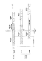
まず、クライアント・サーバシステム1000の構成について、図1を参照して説明する。
Hereinafter, the best mode for carrying out the present invention will be described in detail with reference to the drawings. The scope of the invention is not limited to the illustrated example.
[First embodiment]
First, the client /
<Configuration of client / server system>
First, the configuration of the client /
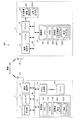
クライアント・サーバシステム1000は、サーバ装置1と、クライアント端末装置2と、を備えて構成される。サーバ装置1とクライアント端末装置2とは、無線ネットワークNを介して接続されており、互いに通信することができるようになっている。
The client /
無線ネットワークNは、例えば、IEEE(Institute of Electrical and Electronic Engineers)802.11規格などに準じた無線LAN(Local Area Network)などのネットワークである。
(サーバ装置の構成)
サーバ装置1は、例えば、図1に示すように、DVD/HDD再生部11と、エンコーダ12と、無線通信部13と、リモコン受信部14と、制御部15と、などを備えて構成される。各部は、バスB1によって接続されている。また、サーバ装置1は、サーバ装置1用のリモートコントローラ141(以下、「リモコン141」という。)も備えている。
The wireless network N is, for example, a network such as a wireless local area network (LAN) conforming to the IEEE (Institute of Electrical and Electronic Engineers) 802.11 standard.
(Configuration of server device)
For example, as shown in FIG. 1, the
DVD/HDD再生部11は、再生手段として、例えば、制御部15からの指示に従って、DVDやHDDに蓄積された映像データを、所定の再生モードで再生する。
The DVD /
ここで、所定の再生モードは、通常再生モード、早送り再生モード、早戻り再生モード、ポーズ再生モードなどを含む。 Here, the predetermined playback modes include a normal playback mode, a fast forward playback mode, a fast return playback mode, a pause playback mode, and the like.
エンコーダ12は、例えば、制御部15からの指示に従って、DVD/HDD再生部11により再生された映像データを、エンコードする。
For example, the
無線通信部13は、アンテナ131等を有しており、無線ネットワークNを介して、クライアント端末装置2の無線通信部21(後述)との間で通信を行う。
The
具体的には、無線通信部13は、例えば、送信手段として、制御部15からの指示に従って、DVD/HDD再生部11により再生されてエンコーダ12によりエンコードされた映像データを、クライアント端末装置2の無線通信部21(後述)に送信する。
Specifically, the
リモコン受信部14は、例えば、リモコン141から送信された各種信号を受信する。
The remote
リモコン141は、例えば、選択手段として、ユーザがDVD/HDD再生部11による再生モードを選択する際に使用される。
The
また、リモコン141は、例えば、設定手段及び入力手段として、ユーザが設定画面S(例えば、図2)に表示された入力欄S1に予測タイムラグを入力する際に使用される。
In addition, the
制御部15は、例えば、図1に示すように、CPU(Central Processing Unit)15
1と、RAM(Random Access Memory)152と、記憶部153と、などを備えている。
For example, as shown in FIG. 1, the
1, a RAM (Random Access Memory) 152, a
CPU151は、記憶部153に記憶されたサーバ装置1用の各種処理プログラムに従って各種の制御動作を行う。
The
RAM152は、CPU151によって実行される処理プログラムなどを展開するためのプログラム格納領域や、入力データや上記処理プログラムが実行される際に生じる処理結果などを格納するデータ格納領域などを備える。
The
記憶部153は、サーバ装置1で実行可能なシステムプログラム、当該システムプログラムで実行可能な各種処理プログラム、これら各種処理プログラムを実行する際に使用されるデータ、CPU151によって演算処理された処理結果のデータなどを記憶する。なお、プログラムは、コンピュータが読み取り可能なプログラムコードの形で記憶部153に記憶されている。
The
具体的には、記憶部153には、例えば、図1に示すように、設定プログラム1531と、制御プログラム1532と、などが記憶されている。
Specifically, the
設定プログラム1531は、CPU151に、ユーザによって予測された、DVD/HDD再生部11により再生された映像データがクライアント端末装置2の出力装置231が有する画像表示部2311等(後述)に出力されるまでのタイムラグ(予測タイムラグ)を設定する機能を実現させる。
The
具体的には、CPU151は、例えば、ユーザによるリモコン141の操作によって入力された予測タイムラグを、記憶部153に記憶させると共に、無線通信部13を介してクライアント端末装置2に送信する。
Specifically, for example, the
CPU151は、かかる設定プログラム1531を実行することによって、設定手段として機能する。
The
制御プログラム1532は、CPU151に、DVD/HDD再生部11による第1の再生モードでの再生動作中に、ユーザによるリモコン141の操作により第2の再生モードが選択された際に、映像データの再生位置を、設定プログラム1531を実行したCPU151により記憶部153に記憶されて設定されたタイムラグ(予測タイムラグ)分に相当する第1の再生モードにおける再生位置まで移動させる処理を行う機能を実現させる。
The
ここで、第1の再生モードは、例えば、通常再生モード、早送り再生モード、早戻し再生モードなどである。また、第2の再生モードは、第1の再生モードと異なる再生モードであって、例えば、通常再生モード、ポーズ再生モードなどである。 Here, the first reproduction mode is, for example, a normal reproduction mode, a fast forward reproduction mode, a fast reverse reproduction mode, or the like. The second playback mode is a playback mode different from the first playback mode, and is, for example, a normal playback mode, a pause playback mode, or the like.
CPU151は、かかる制御プログラム1532を実行することによって、制御手段として機能する。
(クライアント端末装置の構成)
クライアント端末装置2は、例えば、図1に示すように、無線通信部21と、バッファ22と、出力装置231を接続したデコーダ23と、制御部24と、などを備えて構成される。各部は、バスB2によって接続されている。
The
(Configuration of client terminal device)
As shown in FIG. 1, for example, the client terminal device 2 includes a
無線通信部21は、アンテナ211等を有しており、無線ネットワークNを介して、サーバ装置1の無線通信部13との間で通信を行う。
The
具体的には、無線通信部21は、例えば、受信手段として、サーバ装置1の無線通信部13により送信された映像データを受信する。
Specifically, the
バッファ22は、例えば、記憶手段として、制御部24からの指示に従って、無線通信部21により受信された映像データを逐次記憶する。
For example, the
デコーダ23は、例えば、制御部24からの指示に従って、バッファ22に記憶された映像データをデコードして、出力装置231に出力する。
For example, the
出力装置231は、例えば、画像表示部2311と、音声出力部2312と、などを備
えている。
The
画像表示部2311は、液晶表示機器などであり、例えば、表示部として、デコーダ23によりデコードされた映像データに基づく画像を表示する。
The
音声出力部2312は、スピーカ機器などであり、例えば、デコーダ23によりデコードされた映像データに基づく音声を出力する。
The
制御部24は、例えば、図1に示すように、CPU241と、RAM242と、記憶部243と、などを備えている。
For example, as illustrated in FIG. 1, the
CPU241は、記憶部243に記憶されたクライアント端末装置2用の各種処理プログラムに従って各種の制御動作を行う。
The
RAM242は、CPU241によって実行される処理プログラムなどを展開するためのプログラム格納領域や、入力データや上記処理プログラムが実行される際に生じる処理結果などを格納するデータ格納領域などを備える。
The
記憶部243は、クライアント端末装置2で実行可能なシステムプログラム、当該システムプログラムで実行可能な各種処理プログラム、これら各種処理プログラムを実行する際に使用されるデータ、CPU241によって演算処理された処理結果のデータなどを記憶する。なお、プログラムは、コンピュータが読み取り可能なプログラムコードの形で記憶部243に記憶されている。
The
具体的には、記憶部243には、例えば、図1に示すように、出力制御プログラム2431と、設定プログラム2432と、などが記憶されている。
Specifically, the
出力制御プログラム2431は、CPU241に、バッファ22に記憶された映像データを、デコーダ23によりデコードして、出力装置231が有する画像表示部2311等に出力させる機能を実現させる。
The
CPU241は、かかる出力制御プログラム2431を実行することによって、出力制御手段として機能する。
The
設定プログラム2432は、CPU241に、ユーザによって予測された、DVD/HDD再生部11により再生された映像データが出力制御プログラム2431を実行したCPU241により出力装置231が有する画像表示部2311等に出力されるまでのタイムラグ(予測タイムラグ)を設定する機能を実現させる。
The
具体的には、CPU241は、例えば、画像表示部2311に予測タイムラグを設定するための設定画面S(図2)を表示させる。
Specifically, for example, the
CPU241は、かかる設定プログラム2432を実行することによって、設定手段及び設定画面表示制御手段として機能する。
<予測タイムラグ設定処理>
次に、クライアント・サーバシステム1000による予測タイムラグの設定に関する処理について説明する。
The
<Predicted time lag setting process>
Next, processing relating to setting of a predicted time lag by the client /
まず、例えば、ユーザによるリモコン141の操作によって、予測タイムラグを設定するための設定画面S(図2)を、クライアント端末装置2の出力装置231が有する画像表示部2311に表示するよう指示されると、サーバ装置1のCPU151は、設定プログラム1531を実行して、設定画面表示指示を、無線通信部13を介してクライアント端末装置2に送信する。
First, for example, when the user operates the
次いで、当該送信された設定画面表示指示を、クライアント端末装置2の無線通信部2
1が受信すると、クライアント端末装置2のCPU241は、設定プログラム2432を実行して、画像表示部2311に、予測タイムラグを設定するための設定画面S(図2)を表示させる。
Next, the transmitted setting screen display instruction is sent to the wireless communication unit 2 of the client terminal device 2.
When 1 is received, the
そして、当該表示された設定画面S(図2)を見たユーザが、例えば、リモコン141を操作して、予測タイムラグを入力すると、サーバ装置1のCPU151は、設定プログラム1531を実行して、当該入力された予測タイムラグを、記憶部153に記憶させると共に、無線通信部13を介してクライアント端末装置2に送信する。
Then, when the user who sees the displayed setting screen S (FIG. 2), for example, operates the
次いで、当該送信された予測タイムラグを、クライアント端末装置2の無線通信部21が受信すると、クライアント端末装置2のCPU241は、設定プログラム2432を実行して、当該受信した予測タイムラグを、出力装置231に出力して、画像表示部2311に表示された設定画面S(図2)に表示された入力欄S1に入力表示させる。
<再生位置移動処理>
次に、クライアント・サーバシステム1000による映像データの再生位置の移動に関する処理について、図3を参照して説明する。
Next, when the
<Playback position move processing>
Next, processing relating to movement of the reproduction position of video data by the client /
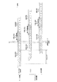
DVD/HDD再生部11により再生された映像データa,b,c,…は、サーバ装置1からクライアント端末装置2に無線送信され、バッファ22に記憶され、出力装置231から出力している。
Video data a, b, c,... Reproduced by the DVD /
図3においては、DVD/HDD再生部11による第1の再生モード(早送り再生モード)での再生動作中に、ユーザによるリモコン141の操作により第2の再生モード(通常再生モード)が選択された場合について説明する。
In FIG. 3, during the playback operation in the first playback mode (fast forward playback mode) by the DVD /
具体的には、DVD/HDD再生部11が早送り再生モードで映像データkを再生し、出力装置231が早送り再生モードで再生された映像データeを出力していた時点[t1]において、ユーザによるリモコン141の操作により通常再生モードが選択された場合、すなわち、ユーザが、映像データeの後に続く映像データ(映像データf以降の映像データ)に基づく映像を、通常再生モードで視聴したい場合について説明する。
Specifically, at the time [t1] when the DVD /
なお、前提として、設定された予測タイムラグ、すなわち、記憶部153に記憶された予測タイムラグが、実際のタイムラグTと合致していることとする。
As a premise, it is assumed that the set predicted time lag, that is, the predicted time lag stored in the
ここで、図3においては、映像データ(例えば、映像データa)が、DVD/HDD再生部11により再生されて、出力装置231に出力されるまでのタイムラグT(=予測タイムラグ)に相当する期間に、DVD/HDD再生部11は、6個の映像データ(映像データb〜g)を、早送り再生モードで再生している。
Here, in FIG. 3, a period corresponding to a time lag T (= predicted time lag) until video data (for example, video data a) is reproduced by the DVD /
DVD/HDD再生部11による早送り再生モードでの再生動作中の時点[t1]において、ユーザによるリモコン141の操作によって、通常再生モードが選択されると、サーバ装置1のCPU151は、制御プログラム1532を実行して、DVD/HDD再生部11を制御して、映像データの再生位置を、映像データkから映像データ6個分(映像データk,j,i,h,g,f)戻った位置まで移動させ、すなわち、映像データkから映像データfまでを早戻し再生モードで再生させ、そして、映像データf以降の映像データを通常再生モードで再生させる。
When the normal playback mode is selected by the user operating the
なお、再生モードの種類によって再生速度が異なるため、タイムラグTに相当する期間に再生される映像データの個数も、再生モードの種類によって異なってくることとなる。したがって、第1の再生モードの種類によって、再生位置の移動距離も変わってくる。 Since the playback speed differs depending on the type of playback mode, the number of video data played back during the period corresponding to the time lag T also differs depending on the type of playback mode. Therefore, the moving distance of the playback position varies depending on the type of the first playback mode.
以上説明した本発明のクライアント・サーバシステム1000によれば、蓄積された映像データを、通常再生モード、早送り再生モード、早戻り再生モード及びポーズ再生モードを含む所定の再生モードで再生するDVD/HDD再生部11と、DVD/HDD再生部11により再生された映像データを送信する無線通信部13と、を有するサーバ装置1と、サーバ装置1に無線ネットワークNを介して接続され、無線通信部13により送信された映像データを受信する無線通信部21と、無線通信部21により受信された映像データを逐次記憶するバッファ22と、バッファ22に記憶された映像データを出力装置231が有する画像表示部2311等に出力させる出力制御プログラム2431を実行したCPU241と、を有するクライアント端末装置2と、を備えている。そして、ユーザはサーバ装置1用のリモコン141を操作して、DVD/HDD再生部11による再生モードを選択することができ、サーバ装置1の設定プログラム1531を実行したCPU151及びクライアント端末装置2の設定プログラム2432を実行したCPU241によって、ユーザによって予測された、DVD/HDD再生部11により再生された映像データが出力制御プログラム2431を実行したCPU241により出力装置231が有する画像表示部2311等に出力されるまでのタイムラグ(予測タイムラグ)を設定することができ、サーバ装置1の制御プログラム1532を実行したCPU151によって、DVD/HDD再生部11を制御して、DVD/HDD再生部11による第1の再生モードでの再生動作中に、ユーザによるリモコン141の操作により第2の再生モードが選択された際に、映像データの再生位置を、設定プログラム1531を実行したCPU151及び設定プログラム2432を実行したCPU241により設定された予測タイムラグ分に相当する第1の再生モードにおける再生位置まで移動させる処理を行うことができる。すなわち、再生位置をユーザ所望の再生位置まで移動させて、そして、当該ユーザ所望の再生位置から、ユーザ所望の再生モードで映像データを再生することができるため、クライアント・サーバシステム1000における映像データの伝送の際に生じる遅延によるユーザ視聴の不具合防止をより汎用的に達成することができる。
According to the client /
さらに、設定プログラム2432を実行したCPU241によって、画像表示部2311に予測タイムラグを設定するための設定画面Sを表示させることができ、ユーザによるリモコン141の操作によって、設定画面Sに表示された入力欄S1に予測タイムラグを入力することができる。したがって、例えば、クライアント・サーバシステム1000の個体差によって、クライアント・サーバシステム1000毎にタイムラグTが異なったとしても、ユーザは、自身が所有するクライアント・サーバシステム1000のタイムラグTに合った予測タイムラグを調整しながら設定することができるため、より効果的に、クライアント・サーバシステム1000における映像データの伝送の際に生じる遅延によるユーザ視聴の不具合防止を達成することができる。
[第2の実施の形態]
次に、第2の実施の形態におけるクライアント・サーバシステム3000について説明する。
<クライアント・サーバシステムの構成>
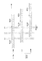
まず、クライアント・サーバシステム3000の構成について、図4を参照して説明する。
Further, the
[Second Embodiment]
Next, a client /
<Configuration of client / server system>
First, the configuration of the client /
なお、第2の実施の形態のクライアント・サーバシステム3000は、設定するタイムラグが第1の実施の形態のクライアント・サーバシステム1000(図1)と異なる。具体的には、サーバ装置1の構成の一部、サーバ装置1におけるリモコン141及びリモコン受信部14の構成の一部、サーバ装置1における制御部15の構成の一部、クライアント端末装置2の構成の一部、クライアント端末装置2における制御部24の構成の一部が異なる。したがって、異なる箇所についてのみ説明し、その他の共通する部分は同一符号を付して詳細な説明は省略する。
The client /
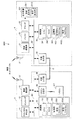
クライアント・サーバシステム3000は、サーバ装置3と、クライアント端末装置4と、を備えて構成される。サーバ装置3とクライアント端末装置4とは、無線ネットワークNを介して接続されており、互いに通信することができるようになっている。
(サーバ装置の構成)
サーバ装置3は、例えば、図4に示すように、DVD/HDD再生部11と、エンコーダ12と、無線通信部13と、リモコン受信部34と、制御部35と、外部入力部36と、などを備えて構成される。各部は、バスB3によって接続されている。また、サーバ装置3は、サーバ装置3用のリモートコントローラ341(以下、「リモコン341」という。)も備えている。
The client /
(Configuration of server device)
For example, as shown in FIG. 4, the server device 3 includes a DVD /
リモコン受信部34は、例えば、リモコン341から送信された各種信号を受信する。
The remote
リモコン341は、例えば、選択手段として、ユーザがDVD/HDD再生部11による再生モードを選択する際に使用される。
The
制御部35は、例えば、図4に示すように、CPU151と、RAM152と、記憶部353と、などを備えている。
For example, as illustrated in FIG. 4, the
記憶部353は、サーバ装置3で実行可能なシステムプログラム、当該システムプログラムで実行可能な各種処理プログラム、これら各種処理プログラムを実行する際に使用されるデータ、CPU151によって演算処理された処理結果のデータなどを記憶する。なお、プログラムは、コンピュータが読み取り可能なプログラムコードの形で記憶部353に記憶されている。
The
具体的には、記憶部353には、例えば、図4に示すように、設定プログラム3531と、制御プログラム3532と、などが記憶されている。
Specifically, the
設定プログラム3531は、CPU151に、DVD/HDD再生部11により再生された映像データがクライアント端末装置4の出力装置231が有する画像表示部2311等に出力されるまでのタイムラグを計測し、当該計測したタイムラグ(計測タイムラグ)を設定する機能を実現させる。
The
具体的には、例えば、CPU151は、DVD/HDD再生部11により再生された一の映像データがケーブルC(後述)を介して外部入力部36に入力されるまでの時間を、計測タイムラグとして計測し、当該計測した計測タイムラグを、記憶部353に記憶させる。
Specifically, for example, the
CPU151は、かかる設定プログラム3531を実行することによって、設定手段及び計測手段として機能する。
The
制御プログラム3532は、CPU151に、DVD/HDD再生部11による第1の再生モードでの再生動作中に、ユーザによるリモコン341の操作により第2の再生モードが選択された際に、映像データの再生位置を、設定プログラム3531を実行したCPU151により記憶部353に記憶されて設定されたタイムラグ(計測タイムラグ)分に相当する第1の再生モードにおける再生位置まで移動させる処理を行う機能を実現させる。
The
ここで、第1の再生モードは、例えば、通常再生モード、早送り再生モード、早戻し再生モードなどである。また、第2の再生モードは、第1の再生モードと異なる再生モードであって、例えば、通常再生モード、ポーズ再生モードなどである。 Here, the first reproduction mode is, for example, a normal reproduction mode, a fast forward reproduction mode, a fast reverse reproduction mode, or the like. The second playback mode is a playback mode different from the first playback mode, and is, for example, a normal playback mode, a pause playback mode, or the like.
CPU151は、かかる制御プログラム3532を実行することによって、制御手段として機能する。
The
外部入力部36は、クライアント端末装置4の外部出力部45(後述)と、設定手段、
計測手段及び通信手段としてのケーブルCによって接続されている。
The
They are connected by a cable C as a measuring means and a communication means.
具体的には、外部入力部36は、例えば、設定手段及び計測手段として、クライアント端末装置4の外部出力部45により出力される映像データを、ケーブルCを介して、入力する。
(クライアント端末装置の構成)
クライアント端末装置4は、例えば、図4に示すように、無線通信部21と、バッファ22と、出力装置231を接続したデコーダ23と、制御部44と、外部出力部45と、などを備えて構成される。
Specifically, the
(Configuration of client terminal device)
As shown in FIG. 4, for example, the client terminal device 4 includes a
制御部44は、例えば、図4に示すように、CPU241と、RAM242と、記憶部443と、などを備えている。
For example, as illustrated in FIG. 4, the
記憶部443は、クライアント端末装置4で実行可能なシステムプログラム、当該システムプログラムで実行可能な各種処理プログラム、これら各種処理プログラムを実行する際に使用されるデータ、CPU241によって演算処理された処理結果のデータなどを記憶する。なお、プログラムは、コンピュータが読み取り可能なプログラムコードの形で記憶部443に記憶されている。
The
具体的には、記憶部443には、例えば、図4に示すように、出力制御プログラム4431と、設定プログラム4432と、などが記憶されている。
Specifically, the
出力制御プログラム4431は、CPU241に、バッファ22に記憶された映像データを、デコーダ23によりデコードして、出力装置231が有する画像表示部2311等に出力させると共に、外部出力部45に出力する機能を実現させる。
The
CPU241は、かかる出力制御プログラム4431を実行することによって、出力制御手段として機能する。
The
設定プログラム4432は、CPU241に、DVD/HDD再生部11により再生された映像データが出力制御プログラム4431を実行したCPU241により出力装置231が有する画像表示部2311等に出力されるまでのタイムラグを計測し、当該計測したタイムラグ(計測タイムラグ)を設定する機能を実現させる。
The
具体的には、CPU241は、出力制御プログラム4431を実行したCPU241により外部出力部45に出力された映像データを、外部出力部45から外部出力して、ケーブルCを介して、サーバ装置3の外部入力部36に入力する。
Specifically, the
CPU241は、かかる設定プログラム4432を実行することによって、設定手段、計測手段及び通信手段として機能する。
The
外部出力部45は、サーバ装置3の外部入力部36と、ケーブルCによって接続されている。
The
具体的には、外部出力部45は、例えば、設定手段及び計測手段として、出力制御プログラム4431を実行したCPU241により出力される映像データを外部出力する。
<計測タイムラグ設定処理>
次に、クライアント・サーバシステム3000による計測タイムラグの設定に関する処理について説明する。
Specifically, the
<Measurement time lag setting process>
Next, processing relating to setting of the measurement time lag by the client /
まず、例えば、クライアント端末装置4の外部出力部45とサーバ装置3の外部入力部36とが、ケーブルCにより接続されている間、クライアント端末装置4のCPU241は、設定プログラム4432を実行して、出力制御プログラム4431を実行したCPU241により出力された映像データを、外部出力部45から外部出力して、ケーブルCを
介して、サーバ装置3の外部入力部36に入力する。
First, for example, while the
そして、例えば、ユーザによるリモコン341の操作によって、計測タイムラグを計測するよう指示されると、サーバ装置3のCPU151は、設定プログラム3531を実行して、DVD/HDD再生部11により再生された一の映像データが、外部入力部36に入力されるまでの時間を計測タイムラグとして計測し、当該計測した計測タイムラグを、記憶部353に記憶させる。
<再生位置移動処理>
クライアント・サーバシステム3000による映像データの再生位置の移動に関する処理については、再生位置の移動距離が、クライアント・サーバシステム1000によれば予測タイムラグによって決まるのに対し、クライアント・サーバシステム3000によれば計測タイムラグによって決まる点以外は、クライアント・サーバシステム1000による映像データの再生位置の移動に関する処理と同一であるため、詳細な説明は省略する。
For example, when the user instructs to measure the measurement time lag by operating the
<Playback position move processing>
Regarding the processing related to the movement of the reproduction position of the video data by the client /
以上説明した本発明のクライアント・サーバシステム3000によれば、クライアント端末装置4側に備えられた外部出力部45によって、クライアント端末装置4の出力制御プログラム4431を実行したCPU241により出力される映像データを外部出力することができ、サーバ装置3側に備えられた外部入力部36によって、ケーブルCを介して、外部出力部45により出力される映像データを入力することができ、そして、サーバ装置3の設定プログラム3531を実行したCPU151及びクライアント端末装置4の設定プログラム4432を実行したCPU241によって、DVD/HDD再生部11により再生された映像データがケーブルCを介して外部入力部36に入力されるまでの時間を、計測タイムラグとして計測して設定することができ、制御プログラム3532を実行したCPU151によって、DVD/HDD再生部11を制御して、DVD/HDD再生部11による第1の再生モードでの再生動作中に、ユーザによるリモコン341の操作により第2の再生モードが選択された際に、映像データの再生位置を、サーバ装置3の設定プログラム3531を実行したCPU151及びクライアント端末装置4の設定プログラム4432を実行したCPU241により設定された計測タイムラグ分に相当する第1の再生モードにおける再生位置まで移動させる処理を行うことができる。したがって、例えば、クライアント・サーバシステム3000の個体差によって、クライアント・サーバシステム3000毎にタイムラグTが異なったとしても、クライアント・サーバシステム3000毎に、クライアント・サーバシステム3000が持つタイムラグTを計測タイムラグとして計測して設定することができると共に、ユーザが視聴の際に実感するタイムラグTを計測タイムラグとして、直接計測して、設定することができるため、より効果的に、クライアント・サーバシステム3000における映像データの伝送の際に生じる遅延によるユーザ視聴の不具合防止を達成することができる。
[第3の実施の形態]
次に、第3の実施の形態におけるクライアント・サーバシステム5000について説明する。
<クライアント・サーバシステムの構成>
まず、クライアント・サーバシステム5000の構成について、図5を参照して説明する。
According to the
[Third embodiment]
Next, a client /
<Configuration of client / server system>
First, the configuration of the client /
なお、第3の実施の形態のクライアント・サーバシステム5000は、再生位置移動処理が第1の実施の形態のクライアント・サーバシステム1000(図1)と異なる。具体的には、サーバ装置1におけるリモコン141及びリモコン受信部14の構成の一部、サーバ装置1における制御部15の構成の一部、クライアント端末装置2の構成の一部、クライアント端末装置2における制御部24の構成の一部が異なる。したがって、異なる箇
所についてのみ説明し、その他の共通する部分は同一符号を付して詳細な説明は省略する。
The client /
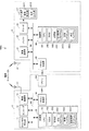
クライアント・サーバシステム5000は、サーバ装置5と、クライアント端末装置6と、を備えて構成される。サーバ装置5とクライアント端末装置6とは、無線ネットワークNを介して接続されており、互いに通信することができるようになっている。
(サーバ装置の構成)
サーバ装置5は、例えば、図5に示すように、DVD/HDD再生部11と、エンコーダ12と、無線通信部13と、リモコン受信部54と、制御部55と、などを備えて構成される。各部は、バスB5によって接続されている。また、サーバ装置5は、サーバ装置5用のリモートコントローラ541(以下、「リモコン541」という。)も備えている。
The client /
(Configuration of server device)
For example, as shown in FIG. 5, the
リモコン受信部54は、例えば、リモコン541から送信された各種信号を受信する。
For example, the remote
リモコン541は、例えば、ユーザがDVD/HDD再生部11による再生モードを選択する際に使用される。
The
また、リモコン541は、例えば、ユーザが設定画面S(図2)に表示された入力欄S1に予測タイムラグを入力する際に使用される。
The
なお、リモコン541は、クライアント端末装置6のリモコン受信部65に対しても、各種信号を送信することができるようになっている。
The
制御部55は、例えば、図5に示すように、CPU151と、RAM152と、記憶部553と、などを備えている。
For example, as illustrated in FIG. 5, the
記憶部553は、サーバ装置5で実行可能なシステムプログラム、当該システムプログラムで実行可能な各種処理プログラム、これら各種処理プログラムを実行する際に使用されるデータ、CPU151によって演算処理された処理結果のデータなどを記憶する。なお、プログラムは、コンピュータが読み取り可能なプログラムコードの形で記憶部553に記憶されている。
The
具体的には、記憶部553には、例えば、図5に示すように、設定プログラム1531と、制御プログラム1532と、送信制御プログラム5533と、などが記憶されている。
Specifically, the
送信制御プログラム5533は、CPU151に、制御プログラム1532を実行したCPU151による映像データの再生位置を移動させる処理中にDVD/HDD再生部11により再生された映像データを、クライアント端末装置6に送信させない処理を行う機能を実現させる。
The
また、送信制御プログラム5533は、CPU151に、DVD/HDD再生部11により第2の再生モードで再生された映像データを、クライアント端末装置6が備えるバッファ22による映像データ記憶許容量に達するまで、通常の送信速度よりも速い速度で送信させる処理を行う機能を実現させる。
Further, the
ここで、通常の送信速度とは、CPU151が送信制御プログラム5533を実行しない際の再生速度、すなわち、例えば、第1の再生モードで再生された映像データがサーバ装置5からクライアント端末装置6に送信される際の送信速度である。
(クライアント端末装置の構成)
クライアント端末装置6は、例えば、図5に示すように、無線通信部21と、バッファ22と、出力装置231を接続したデコーダ23と、制御部64と、リモコン受信部65と、などを備えて構成される。各部は、バスB6によって接続されている。
Here, the normal transmission speed is a reproduction speed when the
(Configuration of client terminal device)
As shown in FIG. 5, for example, the client terminal device 6 includes a
ここで、クライアント端末装置6は、サーバ装置5用のリモコン541によって操作可能となっている。
Here, the client terminal device 6 can be operated by the
制御部64は、例えば、図5に示すように、CPU241と、RAM242と、記憶部643と、などを備えている。
For example, as shown in FIG. 5, the
記憶部643は、クライアント端末装置6で実行可能なシステムプログラム、当該システムプログラムで実行可能な各種処理プログラム、これら各種処理プログラムを実行する際に使用されるデータ、CPU241によって演算処理された処理結果のデータなどを記憶する。なお、プログラムは、コンピュータが読み取り可能なプログラムコードの形で記憶部643に記憶されている。
The
具体的には、記憶部643には、例えば、図5に示すように、出力制御プログラム6431と、設定プログラム2432と、消去プログラム6433と、などが記憶されている。
Specifically, the
出力制御プログラム6431は、CPU241に、バッファ22に記憶された映像データを、デコーダ23によりデコードして、出力装置231が有する画像表示部2311等に出力させる機能を実現させる。
The
また、出力制御プログラム6431は、CPU241に、ユーザによるリモコン541の操作により第2の再生モードが選択されてから、DVD/HDD再生部11により第2の再生モードで再生された映像データを出力装置231が有する画像表示部2311等に出力させるまでの間、ユーザによるリモコン541の操作により第2の再生モードが選択された時点で画像表示部2311に表示されていた映像データに基づく画像(静止画像)を、画像表示部2311に表示させる機能を実現させる。
The
消去プログラム6433は、CPU241に、ユーザによるリモコン541の操作により第2の再生モードが選択された時点でバッファ22に記憶されている第1の再生モードで再生された映像データと、ユーザによるリモコン541の操作により第2の再生モードが選択された後にバッファ22に記憶される第1の再生モードで再生された映像データと、をバッファ22から消去する機能を実現する。
The erasing
リモコン受信部65は、例えば、サーバ装置5用のリモコン541から送信された各種信号を受信する。
<予測タイムラグ設定処理>
クライアント・サーバシステム5000による予測タイムラグの設定に関する処理については、クライアント・サーバシステム1000による予測タイムラグの設定に関する処理と同一であるため、詳細な説明は省略する。
<再生位置移動処理>
クライアント・サーバシステム5000による映像データの再生位置の移動に関する処理について、図6を参照して説明する。
The
<Predicted time lag setting process>
Since the processing related to the setting of the predicted time lag by the client /
<Playback position move processing>
Processing relating to movement of the reproduction position of video data by the client /
DVD/HDD再生部11により再生された映像データa,b,c,…は、サーバ装置5からクライアント端末装置6に無線送信され、バッファ22に記憶され、出力装置231から出力している。
Video data a, b, c,... Reproduced by the DVD /
図6においては、図3と同様、DVD/HDD再生部11による第1の再生モード(早送り再生モード)での再生動作中に、ユーザによるリモコン541の操作により第2の再生モード(通常再生モード)が選択された場合について説明する。
In FIG. 6, as in FIG. 3, during the playback operation in the first playback mode (fast forward playback mode) by the DVD /
具体的には、DVD/HDD再生部11が早送り再生モードで映像データkを再生し、出力装置231が早送り再生モードで再生された映像データeを出力していた時点[t1]において、ユーザによるリモコン541の操作により通常再生モードが選択された場合、すなわち、ユーザが、映像データeの後に続く映像データ(映像データf以降の映像データ)に基づく映像を、通常再生モードで視聴したい場合について説明する。
Specifically, at the time [t1] when the DVD /
なお、図3と同様、前提として、設定された予測タイムラグ、すなわち、記憶部553に記憶された予測タイムラグが、実際のタイムラグTと合致していることとする。
As in FIG. 3, it is assumed that the set prediction time lag, that is, the prediction time lag stored in the
ここで、図6においては、図3と同様、映像データ(例えば、映像データa)が、DVD/HDD再生部11により再生されて、出力装置231に出力されるまでのタイムラグT(=予測タイムラグ)に相当する期間に、DVD/HDD再生部11は、6個の映像データ(映像データb〜g)を、早送り再生モードで再生している。
Here, in FIG. 6, as in FIG. 3, a time lag T (= predicted time lag) until video data (for example, video data a) is reproduced by the DVD /
DVD/HDD再生部11による早送り再生モードでの再生動作中の時点[t1]において、ユーザによるリモコン541の操作によって、通常再生モードが選択されると、サーバ装置5のCPU151は、制御プログラム1532を実行して、DVD/HDD再生部11を制御して、映像データの再生位置を、映像データkから映像データ6個分(映像データk,j,i,h,g,f)戻った位置まで移動させ、すなわち、映像データkから映像データfまでを早戻し再生モードで再生させ、そして、映像データf以降の映像データを通常再生モードで再生させる。
When the normal playback mode is selected by the user operating the
また、CPU151は、時点[t1]において、送信制御プログラム5533を実行して、無線通信部13を制御して、制御プログラム1532を実行したCPU151による映像データの再生位置を移動させる処理中にDVD/HDD再生部11により早戻し再生モードで再生された映像データ(映像データk,j,i,h,g,f)を、クライアント端末装置6の無線通信部21に送信させないようにする。そして、DVD/HDD再生部11により通常再生モードで映像データが再生されると、CPU151は、当該通常再生モードで再生された映像データ(映像データf,g,h,…)を、通常の送信速度よりも速い速度で、すなわち、早送り再生モードで再生された映像データ(映像データa〜k)を送信するよりも速い速度で送信させる。
At the time [t1], the
一方、クライアント端末装置のCPU241は、時点[t1]において、消去プログラム6433を実行して、時点[t1]の時点でバッファ22に記憶されている早送り再生モードで再生された映像データ(映像データf,g,h)と、時点[t1]の後にバッファ22に記憶される早送り再生モードで再生された映像データ(映像データi,j,k)と、をバッファ22から消去する。
On the other hand, the
また、出力制御プログラム6431を実行したCPU241は、時点[t1]において、時点[t1]から、バッファ22に記憶された通常再生モードで再生された映像データ(映像データf以降の映像データ)を出力装置231が有する画像表示部2311等に出力させるまでの間、時点[t1]の時点で画像表示部2311に表示されていた映像データ(映像データe)に基づく静止画像を、画像表示部2311に表示させる。
Further, the
なお、図3の場合と同様、再生モードの種類によって再生速度が異なるため、タイムラグTに相当する期間に再生される映像データの個数も、再生モードの種類によって異なってくることとなる。したがって、第1の再生モードの種類によって、再生位置の移動距離も変わってくる。 As in the case of FIG. 3, since the playback speed varies depending on the type of playback mode, the number of video data played back during the period corresponding to the time lag T also varies depending on the type of playback mode. Therefore, the moving distance of the playback position varies depending on the type of the first playback mode.
以上説明した本発明のクライアント・サーバシステム5000によれば、リモコン受信部65によって、サーバ装置5用のリモコン541から送信された各種信号を受信することができる。そして、サーバ装置1の送信制御プログラム5533を実行したCPU151によって、無線通信部13を制御して、制御プログラム1532を実行したCPU15
1による映像データの再生位置を移動させる処理中にDVD/HDD再生部11により再生された映像データを、クライアント端末装置6に送信させない処理を行うことができ、クライアント端末装置2の消去プログラム6433を実行したCPU241によって、ユーザによるリモコン541の操作により第2の再生モードが選択された時点でバッファ22に記憶されている第1の再生モードで再生された映像データと、ユーザによるリモコン541の操作により第2の再生モードが選択された後にバッファ22に記憶される第1の再生モードで再生された映像データと、をバッファ22から消去することができ、クライアント端末装置2の出力制御プログラム6431を実行したCPU241によって、バッファ22に記憶された映像データを、デコーダ23によりデコードして、出力装置231が有する画像表示部2311等に出力させることができると共に、ユーザによるリモコン541の操作により第2の再生モードが選択されてから、DVD/HDD再生部11により第2の再生モードで再生された映像データを出力装置231が有する画像表示部2311等に出力させるまでの間、ユーザによるリモコン541の操作により第2の再生モードが選択された時点で画像表示部2311に表示されていた映像データに基づく画像(静止画像)を、画像表示部2311に表示させることができる。したがって、ユーザは、第2の再生モードを選択した後は、第1の再生モードで再生された映像や再生位置の移動の際に再生される映像データに基づく映像を視聴することなく、ユーザ所望の再生位置からユーザ所望の再生モードで再生された映像データに基づく映像を視聴することができる。
According to the client /
The video data reproduced by the DVD /
さらに、送信制御プログラム5533を実行したCPU151によって、無線通信部13を制御して、DVD/HDD再生部11により第2の再生モードで再生された映像データを、クライアント端末装置6が備えるバッファ22による映像データ記憶許容量に達するまで、通常の送信速度よりも速い速度で送信させる処理を行うことができる。したがって、ユーザ所望の再生モードで再生されたユーザ所望の映像データを、いち早く出力することができるため、より効果的に、クライアント・サーバシステム5000における映像データの伝送の際に生じる遅延によるユーザ視聴の不具合防止を達成することができる。
Further, the
なお、本発明は、上記した実施の形態のものに限るものではなく、その要旨を逸脱しない範囲で適宜変更可能である。 The present invention is not limited to the above-described embodiment, and can be appropriately changed without departing from the gist thereof.
第1〜3の実施の形態におけるサーバ装置1,3,5が有する再生手段は、DVD/HDD再生部11の限りではなく、蓄積された映像データを、通常再生モード、早送り再生モード、早戻し再生モード及びポーズ再生モードを含む所定の再生モードで再生することができる、好適なAV機器(例えば、VCR(Video Cassette Recorder)再生器等)で
あれば任意である。
The reproduction means included in the
また、第1〜3の実施の形態におけるサーバ装置1,3,5に、DVD/HDD再生部11を備えるようにしたが、DVD/HDD再生部11とサーバ装置1,3,5とを別体にして、DVD/HDD再生部11をサーバ装置1,3,5に接続するようにしてもよい。
Further, the
同様に、第1〜3の実施の形態におけるクライアント端末装置2,4,6に、画像表示部2311等を有する出力装置231を備えるようにしたが、出力装置231とクライアント端末装置2,4,6とを別体にして、出力装置231をクライアント端末装置2,4,6に接続するようにしてもよい。
Similarly, the client terminal devices 2, 4, 6 in the first to third embodiments are provided with the
第2の実施の形態において、計測タイムラグを計測する際、有線で、DVD/HDD再生部11により再生された映像データを、クライアント端末装置4からサーバ装置3に戻すようにしたが、例えば、無線で映像データを戻すようにしてもよい。この場合、例えば、クライアント端末装置4が備える無線通信部21と、サーバ装置3が備える無線通信部13と、を用いるようにするとよい。
In the second embodiment, when measuring the measurement time lag, the video data reproduced by the DVD /
また、計測タイムラグの計測方法は、第2の実施の形態の限りではなく、好適な方法であれば任意である。 Further, the measurement method of the measurement time lag is not limited to the second embodiment, and any method can be used as long as it is a suitable method.
第3の実施の形態においては、第1の実施の形態と同様、予測タイムラグを記憶部553に記憶して設定するようにしたが、第2の実施の形態と同様、計測タイムラグを記憶部553に記憶して設定するようにしてもよい。
In the third embodiment, the predicted time lag is stored and set in the
第1の実施の形態の再生位置移動処理(図3)及び第3の実施の形態の再生位置移動処理(図6)において、第1の再生モードを早送り再生モードとし、第2の再生モードを通常再生モードとしたが、第1の再生モードは、早送り再生モード、早戻し再生モード、通常再生モードのうち何れかであれば制限はなく、また、第2の再生モードは、第1の再生モードと異なる再生モードであり、且つ、通常再生モード、ポーズ再生モードのうちの何れかであれば制限はない。 In the reproduction position movement process (FIG. 3) of the first embodiment and the reproduction position movement process (FIG. 6) of the third embodiment, the first reproduction mode is set to the fast-forward reproduction mode, and the second reproduction mode is set. Although the normal playback mode is set, there is no limitation as long as the first playback mode is any one of the fast-forward playback mode, the fast-rewind playback mode, and the normal playback mode, and the second playback mode is the first playback mode. There is no limitation as long as the playback mode is different from the mode and any one of the normal playback mode and pause playback mode.
1,3,5 サーバ装置
11 DVD/HDD再生部(再生手段)
13 無線通信部(送信手段)
141 リモコン(選択手段、設定手段、入力手段)
151 CPU(設定手段、制御手段、計測手段)
1531 設定プログラム(設定手段)
1532 制御プログラム(制御手段)
36 外部入力部(設定手段、計測手段)
341 リモコン(選択手段)
3531 設定プログラム(設定手段、計測手段)
3532 制御プログラム(制御手段)
2,4,6 クライアント端末装置
21 無線通信部(受信手段)
22 バッファ(記憶手段)
241 CPU(出力制御手段、設定手段、設定画面表示制御手段、計測手段、通信手段)
2311 画像表示部(表示部)
2431 出力制御プログラム(出力制御手段)
2432 設定プログラム(設定手段、設定画面表示制御手段)
45 外部出力部(設定手段、計測手段)
4431 出力制御プログラム(出力制御手段)
4432 設定プログラム(設定手段、計測手段、通信手段)
1000,3000,5000 クライアント・サーバシステム
C ケーブル(設定手段、計測手段、通信手段)
N 無線ネットワーク
S 設定画面
S1 入力欄
1, 3, 5
13 Wireless communication unit (transmission means)
141 Remote control (selection means, setting means, input means)
151 CPU (setting means, control means, measuring means)
1531 Setting program (setting means)
1532 Control program (control means)
36 External input unit (setting means, measuring means)
341 Remote control (selection means)
3531 Setting program (setting means, measuring means)
3532 Control program (control means)
2, 4, 6
22 Buffer (storage means)
241 CPU (output control means, setting means, setting screen display control means, measurement means, communication means)
2311 Image display unit (display unit)
2431 Output control program (output control means)
2432 Setting program (setting means, setting screen display control means)
45 External output unit (setting means, measuring means)
4431 Output control program (output control means)
4432 Setting program (setting means, measuring means, communication means)
1000, 3000, 5000 Client / server system C cable (setting means, measuring means, communication means)
N Wireless network S Setting screen S1 Input field
Claims (4)
前記再生手段による再生モードを選択する選択手段と、
前記再生手段により再生された映像データが、前記出力制御手段により前記表示部に出力されるまでのタイムラグを設定する設定手段と、
前記再生手段による第1の再生モードでの再生動作中に、前記選択手段により第2の再生モードが選択された際に、映像データの再生位置を、前記設定手段により設定されたタイムラグ分に相当する前記第1の再生モードにおける再生位置まで移動させる処理を行う制御手段と、
を備え、
前記設定手段は、
前記表示部に設定画面を表示させる設定画面表示制御手段と、
前記設定画面に表示された入力欄に前記タイムラグを入力するための入力手段と、
を備えることを特徴とするクライアント・サーバシステム。 Reproducing means for reproducing the accumulated video data in a predetermined reproduction mode including a normal reproduction mode, a fast forward reproduction mode and a fast return reproduction mode, and a transmission means for transmitting the video data reproduced by the reproduction means. A server device, a receiving unit connected to the server device via a wireless network and receiving the video data transmitted by the transmitting unit, a storage unit sequentially storing the video data received by the receiving unit, In a client / server system comprising: a client terminal device having output control means for causing the display unit to output video data stored in the storage means;
Selection means for selecting a playback mode by the playback means;
Setting means for setting a time lag until the video data reproduced by the reproduction means is output to the display unit by the output control means;
When the second playback mode is selected by the selection unit during the playback operation in the first playback mode by the playback unit, the playback position of the video data corresponds to the time lag set by the setting unit. Control means for performing processing for moving to the playback position in the first playback mode;
With
The setting means includes
Setting screen display control means for displaying a setting screen on the display unit;
An input means for inputting the time lag in the input field displayed on the setting screen;
A client-server system comprising:
前記再生手段による再生モードを選択する選択手段と、
前記再生手段により再生された映像データが、前記出力制御手段により前記表示部に出力されるまでのタイムラグを設定する設定手段と、
前記再生手段による第1の再生モードでの再生動作中に、前記選択手段により第2の再生モードが選択された際に、映像データの再生位置を、前記設定手段により設定されたタイムラグ分に相当する前記第1の再生モードにおける再生位置まで移動させる処理を行う制御手段と、
を備え、
前記設定手段は、前記タイムラグを計測する計測手段を備え、
前記計測手段は、
前記クライアント端末装置側に備えられ、前記出力制御手段により出力される映像データを外部出力する外部出力部と、
前記サーバ装置側に備えられ、前記外部出力部により出力される映像データを入力する外部入力部と、
前記外部出力部と前記外部入力部とを接続する通信手段と、
を備え、
前記再生手段により再生された映像データが前記通信手段を介して前記外部入力部に入力されるまでの時間を、前記タイムラグとして計測することを特徴とするクライアント・サーバシステム。 Reproducing means for reproducing the accumulated video data in a predetermined reproduction mode including a normal reproduction mode, a fast forward reproduction mode and a fast return reproduction mode, and a transmission means for transmitting the video data reproduced by the reproduction means. A server device, a receiving unit connected to the server device via a wireless network and receiving the video data transmitted by the transmitting unit, a storage unit sequentially storing the video data received by the receiving unit, In a client / server system comprising: a client terminal device having output control means for causing the display unit to output video data stored in the storage means;
Selection means for selecting a playback mode by the playback means;
Setting means for setting a time lag until the video data reproduced by the reproduction means is output to the display unit by the output control means;
When the second playback mode is selected by the selection unit during the playback operation in the first playback mode by the playback unit, the playback position of the video data corresponds to the time lag set by the setting unit. Control means for performing processing for moving to the playback position in the first playback mode;
With
The setting means includes a measuring means for measuring the time lag,
The measuring means includes
An external output unit provided on the client terminal device side and externally outputting video data output by the output control means;
An external input unit that is provided on the server device side and that inputs video data output by the external output unit;
Communication means for connecting the external output unit and the external input unit;
With
A client / server system characterized in that a time until video data reproduced by the reproduction means is input to the external input unit via the communication means is measured as the time lag.
含む所定の再生モードで再生する再生手段と、前記再生手段により再生された映像データを送信する送信手段と、を有するサーバ装置と、前記サーバ装置に無線ネットワークを介して接続され、前記送信手段により送信された映像データを受信する受信手段と、前記受信手段により受信された映像データを逐次記憶する記憶手段と、前記記憶手段に記憶された映像データを表示部に出力させる出力制御手段と、を有するクライアント端末装置と、を備えたクライアント・サーバシステムにおいて、
前記再生手段による再生モードを選択する選択手段と、
前記再生手段により再生された映像データが、前記出力制御手段により前記表示部に出力されるまでのタイムラグを設定する設定手段と、
前記再生手段による第1の再生モードでの再生動作中に、前記選択手段により第2の再生モードが選択された際に、映像データの再生位置を、前記設定手段により設定されたタイムラグ分に相当する前記第1の再生モードにおける再生位置まで移動させる処理を行う制御手段と、
を備えることを特徴とするクライアント・サーバシステム。 Reproducing means for reproducing the accumulated video data in a predetermined reproduction mode including a normal reproduction mode, a fast forward reproduction mode and a fast return reproduction mode, and a transmission means for transmitting the video data reproduced by the reproduction means. A server device, a receiving unit connected to the server device via a wireless network and receiving the video data transmitted by the transmitting unit, a storage unit sequentially storing the video data received by the receiving unit, In a client / server system comprising: a client terminal device having output control means for causing the display unit to output video data stored in the storage means;
Selection means for selecting a playback mode by the playback means;
Setting means for setting a time lag until the video data reproduced by the reproduction means is output to the display unit by the output control means;
When the second playback mode is selected by the selection unit during the playback operation in the first playback mode by the playback unit, the playback position of the video data corresponds to the time lag set by the setting unit. Control means for performing processing for moving to the playback position in the first playback mode;
A client-server system comprising:
前記設定手段は、
前記タイムラグを計測する計測手段を備えていることを特徴とするクライアント・サーバシステム。 In the client server system according to claim 3,
The setting means includes
A client / server system comprising measuring means for measuring the time lag.
Priority Applications (2)
| Application Number | Priority Date | Filing Date | Title |
|---|---|---|---|
| JP2005265400A JP2007081663A (en) | 2005-09-13 | 2005-09-13 | Client server system |
| US11/519,004 US7657647B2 (en) | 2005-09-13 | 2006-09-12 | Client server system |
Applications Claiming Priority (1)
| Application Number | Priority Date | Filing Date | Title |
|---|---|---|---|
| JP2005265400A JP2007081663A (en) | 2005-09-13 | 2005-09-13 | Client server system |
Publications (1)
| Publication Number | Publication Date |
|---|---|
| JP2007081663A true JP2007081663A (en) | 2007-03-29 |
Family
ID=37941518
Family Applications (1)
| Application Number | Title | Priority Date | Filing Date |
|---|---|---|---|
| JP2005265400A Pending JP2007081663A (en) | 2005-09-13 | 2005-09-13 | Client server system |
Country Status (2)
| Country | Link |
|---|---|
| US (1) | US7657647B2 (en) |
| JP (1) | JP2007081663A (en) |
Cited By (1)
| Publication number | Priority date | Publication date | Assignee | Title |
|---|---|---|---|---|
| JP2014072651A (en) * | 2012-09-28 | 2014-04-21 | Kddi Corp | Image content distributing apparatus |
Families Citing this family (5)
| Publication number | Priority date | Publication date | Assignee | Title |
|---|---|---|---|---|
| WO2008058020A2 (en) * | 2006-11-02 | 2008-05-15 | Diaserve, Inc. | Biological polymeric compositions and methods related thereto |
| US20100031302A1 (en) * | 2008-07-30 | 2010-02-04 | Kabushiki Kaisha Toshiba | Stream distribution system, stream receiving device, and stream reproduction method |
| TWI450101B (en) * | 2010-09-21 | 2014-08-21 | Insyde Software Corp | Remote data transmitting method and virtual media system using the method |
| TWI505101B (en) * | 2013-12-17 | 2015-10-21 | Inventec Corp | Data transmitting apparatus and method |
| US11206393B2 (en) | 2017-09-22 | 2021-12-21 | Microsoft Technology Licensing, Llc | Display latency measurement system using available hardware |
Family Cites Families (6)
| Publication number | Priority date | Publication date | Assignee | Title |
|---|---|---|---|---|
| JP3617089B2 (en) * | 1993-12-27 | 2005-02-02 | 株式会社日立製作所 | Video storage / delivery device and video storage / delivery system |
| JPH08107540A (en) | 1994-10-06 | 1996-04-23 | Matsushita Electric Ind Co Ltd | Compressed video playback device |
| JPH11127420A (en) | 1997-10-24 | 1999-05-11 | Matsushita Electric Ind Co Ltd | Video supply system |
| JP2002291065A (en) | 2001-03-26 | 2002-10-04 | Sharp Corp | Wireless transmission and reception system |
| JP3801507B2 (en) | 2002-01-15 | 2006-07-26 | シャープ株式会社 | Video transmission device |
| JP2005204273A (en) * | 2003-12-15 | 2005-07-28 | D & M Holdings Inc | Av system, av device, and image signal outputting method |
-
2005
- 2005-09-13 JP JP2005265400A patent/JP2007081663A/en active Pending
-
2006
- 2006-09-12 US US11/519,004 patent/US7657647B2/en active Active
Cited By (1)
| Publication number | Priority date | Publication date | Assignee | Title |
|---|---|---|---|---|
| JP2014072651A (en) * | 2012-09-28 | 2014-04-21 | Kddi Corp | Image content distributing apparatus |
Also Published As
| Publication number | Publication date |
|---|---|
| US7657647B2 (en) | 2010-02-02 |
| US20070122107A1 (en) | 2007-05-31 |
Similar Documents
| Publication | Publication Date | Title |
|---|---|---|
| KR100747575B1 (en) | Broadcast signal reproduction method and device | |
| WO2007148777A1 (en) | Reproduction device, method, and program | |
| JP5879169B2 (en) | Subtitle synchronized playback apparatus and program thereof | |
| JP2018098664A (en) | Recording apparatus, control method therefor, computer program, and recording medium | |
| JP4730590B2 (en) | Control device and method, information processing device and method, and program | |
| JP2007081663A (en) | Client server system | |
| KR100763385B1 (en) | Broadcast signal output method and device | |
| JP7314102B2 (en) | CONTROL SIGNAL GENERATING CIRCUIT, RECEIVER, SYSTEM, GENERATING METHOD, AND PROGRAM | |
| US20060218603A1 (en) | AV transmission system | |
| US7646961B2 (en) | Data recording and reproduction apparatus | |
| US20080187294A1 (en) | Playback apparatus, playback method, and program | |
| JP3801507B2 (en) | Video transmission device | |
| US20050286362A1 (en) | Disc reproduction apparatus capable of digest reproduction | |
| JP5487771B2 (en) | Recording / reproducing apparatus, recording / reproducing control method, and editing system | |
| US20070160341A1 (en) | Video signal playback unit and video signal playback method | |
| JP4678495B2 (en) | Information processing apparatus and method, and program | |
| US8498522B2 (en) | Multimedia data recording/playing device and driving method thereof | |
| KR100826184B1 (en) | Imaging device with momentary movement function of recordings and its control method | |
| KR20080065977A (en) | Search tool | |
| JP6345324B2 (en) | Television receiver | |
| JP6195723B2 (en) | Television receiver | |
| US20080010363A1 (en) | Communication apparatus and communication method | |
| KR100899237B1 (en) | Recording Control Device and Method of Image Display Equipment | |
| JP2006041758A (en) | Video reproducing apparatus | |
| KR20070056744A (en) | Video data recording / playback method and apparatus therefor |