JP2007055352A - Vehicular display device and assembling method thereof - Google Patents
Vehicular display device and assembling method thereof Download PDFInfo
- Publication number
- JP2007055352A JP2007055352A JP2005241035A JP2005241035A JP2007055352A JP 2007055352 A JP2007055352 A JP 2007055352A JP 2005241035 A JP2005241035 A JP 2005241035A JP 2005241035 A JP2005241035 A JP 2005241035A JP 2007055352 A JP2007055352 A JP 2007055352A
- Authority
- JP
- Japan
- Prior art keywords
- drive
- belt
- display device
- driving
- state
- Prior art date
- Legal status (The legal status is an assumption and is not a legal conclusion. Google has not performed a legal analysis and makes no representation as to the accuracy of the status listed.)
- Pending
Links
- 238000000034 method Methods 0.000 title claims abstract description 25
- 238000001514 detection method Methods 0.000 description 6
- 230000004308 accommodation Effects 0.000 description 2
- 230000006866 deterioration Effects 0.000 description 2
- 230000000694 effects Effects 0.000 description 2
- 230000007704 transition Effects 0.000 description 2
- 102100027340 Slit homolog 2 protein Human genes 0.000 description 1
- 101710133576 Slit homolog 2 protein Proteins 0.000 description 1
- 238000007792 addition Methods 0.000 description 1
- 238000009434 installation Methods 0.000 description 1
- 238000011900 installation process Methods 0.000 description 1
- 230000000149 penetrating effect Effects 0.000 description 1
Images


Abstract
Description
本発明は、車両に取り付けられ、表示により情報を乗員に伝達する技術に関する。 The present invention relates to a technique that is attached to a vehicle and transmits information to a passenger by display.
従来の技術においては、倒れた状態で表示面を下向きになるよう収納したモニタの奥側の一部を軸として回転させて起動させている(例えば、特許文献1参照。)。
しかしながら、従来では、起立したモニタの下端より上方で、且つモニタから離れた位置まで支持アームを伸ばし、その支持アームの端部を中心にモニタを回転させることで、倒れた収納状態と起立状態にするため、下方に空間を多く必要とする構成であった。また、この構成では、駆動機構や駆動のためのアクチュエータも下方に設けるのが効率的であり、さらに下方に空間を多く必要としていた。 However, conventionally, the support arm is extended to a position above the lower end of the standing monitor and away from the monitor, and the monitor is rotated around the end of the support arm, so that the fallen storage state and the standing state are achieved. Therefore, the configuration requires a lot of space below. Further, in this configuration, it is efficient to provide a driving mechanism and an actuator for driving below, and more space is required below.
本発明は、上記問題に着目してなされたもので、その目的とするところは、下方に空間を多く必要としない薄型な構成で、薄型な構成であってもコストを抑制しつつ組み付けを容易にすることができる車両用表示装置及び組付方法を提供することにある。 The present invention has been made paying attention to the above-mentioned problems, and the object of the present invention is a thin configuration that does not require a lot of space below, and it is easy to assemble while suppressing the cost even with a thin configuration. Another object of the present invention is to provide a vehicle display device and an assembling method.
上記目的を達成するため、本発明では、表示パネルが見やすく起立した起立状態と、前記表示パネルが倒れた収納状態を、ベルトの駆動による前後のスライド手段とリンク機構により移行自在にする可動手段を備える車両用表示装置において、ベルト駆動系の駆動位置を検出する駆動位置検出手段と、起立状態と収納状態を前記駆動位置により判断してベルト駆動の制御を行なう制御部と、を備え、前記ベルトを組み付ける前に前記駆動位置検出手段を組み付けた状態で、収納状態よりも起立状態側の駆動位置に駆動させ、ベルトを組み付けた後に収納状態でさらに前記パネルを収納側に負荷を加えた駆動位置まで駆動させ、収納状態の駆動位置を設定する初期位置設定手段を設けた、ことを特徴とする。 In order to achieve the above object, according to the present invention, there is provided movable means for allowing the display panel to stand up in an easy-to-read manner and the storage state in which the display panel is tilted to be shifted by a front and rear slide means and a link mechanism. The vehicle display device includes: a drive position detecting unit that detects a drive position of the belt drive system; and a control unit that controls the belt drive by determining the standing state and the storage state based on the drive position. Drive position where the drive position detecting means is assembled before assembly, and the panel is driven to the drive position in the standing state with respect to the storage state, and the load is further applied to the storage side in the storage state after the belt is assembled. And initial position setting means for setting the drive position in the retracted state is provided.
よって、薄型な構成にしつつ、コストを抑制でき、組み付けを容易にすることができる。 Therefore, the cost can be suppressed and the assembly can be facilitated while the configuration is thin.
以下、本発明の車両用表示装置及び組付方法を実現する実施の形態を、請求項1に係る発明に対応する実施例1に基づいて説明する。
Hereinafter, an embodiment for realizing the vehicle display device and the assembling method of the present invention will be described based on Example 1 corresponding to the invention according to
まず、構成を説明する。
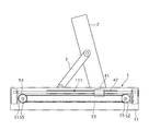
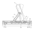
図1は実施例1の車両用表示装置の起動状態の一部を透視した側面図である。図2は車両用表示装置の動作を示す説明図である。
車両用表示装置は、表示器本体1、モニタ2、ヒンジ部3、スライド機構部4、駆動機構部5を主要な構成としている。
First, the configuration will be described.
FIG. 1 is a side view of a part of the starting state of the vehicle display device according to the first embodiment. FIG. 2 is an explanatory view showing the operation of the vehicle display device.
The vehicular display device mainly includes a
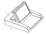
実施例1の車両用表示装置は、モニタ2の収納状態では、表示器本体1の上面と、モニタ2の背面が、およそ1面を成すものである。つまり、車両用表示装置のモニタ2の収納状態では、車両のインストルメントパネルの1面と一体化が可能となる。また、一体化しない場合であっても、ドライバの視界を妨げないよう高さの低い収納状態となる(図3,図4参照)。
表示器本体1の底面に相当する大きさの1面と、両側の側面で、上方が開口するコ字状の本体ブラケット11を設ける。
In the vehicular display device according to the first embodiment, when the
A U-shaped
次に、スライド機構部4について説明する。
スライド機構部4は、スリット111、スライダ41、シャフト42を主要な構成とする。
まず、本体ブラケット11で両端を支持して、前後方向に長くなるよう表示器本体1の両側にシャフト42を設ける。さらに、本体ブラケット11の側面には、前後に長いスリット111を設ける。スライダ41は、前後に貫通する穴を有し、この穴にシャフト42を貫通させるようにする。これにより、スライダ41は前後にスライド自在となる。
Next, the slide mechanism unit 4 will be described.
The slide mechanism unit 4 includes a
First, both ends are supported by the
ここで、モニタ2の取り付け構造を説明しておく。
モニタ2は下端をスリット111に移動自在に係合させて、スリット111に沿って、スリット111の長さのみ下端が移動できるようにする。さらに、モニタ2の下端は、スライダ41に回転自在に取り付けて、スライダ41の動きで、モニタ2の下端を動作させるようにする。
表示器本体1の両側に、モニタ2の起立・収納の回転方向に回転自在にヒンジ部3の一端を取り付け、反対側の端は、モニタ2の側部中央付近に回転自在に取り付ける。
さらに、起立させた状態のモニタ2の側部下端部をスライダ41に回転自在に取り付ける。
Here, the mounting structure of the
The
One end of the
Further, the lower end portion of the side portion of the
次に、駆動機構部5について説明する。
駆動機構部5は、プーリ51,52、駆動ベルト53、駆動モータ54、制御基板、回転軸55、減速機構56、回転センサ57、制御部58を主要な構成とする(図5参照)。
まず本体ブラケット11の両側の側面を前後の位置で貫通するように回転軸55を設ける。後方の回転軸55の両端には、プーリ51を取り付け、前方の回転軸55の両端には、プーリ52を取り付ける。
プーリ51,52の外周には、駆動ベルト53の歯面と係合する歯面を設けるようにする。
駆動ベルト53は、内周にラックのような歯面を設け、前後のプーリ51,52に掛け渡すようにして、左右にそれぞれ設ける。
また、本体ブラケット11の平面上には、図示しない制御基板と、後方の回転軸55を駆動する駆動モータ54を設ける。
駆動モータ54は、制御基板の制御部58により駆動制御される。また、駆動モータ54の出力軸は減速機構56を介して回転軸55に接続される。
さらに、駆動ベルト53の上側の往路の一部をスライダ41に取り付け、駆動ベルト53によりスライダ41を移動させるようにする。
回転センサ57は、回転軸55に円盤を取り付け、円盤の回転を読み取るようにして、回転位置を検出する。回転センサ57は不感帯を有し、360度に達しない範囲を読む取るものである。回転センサ57は検出信号を制御部58へ出力する。
制御部58は、回転センサ57の検出信号から、モニタ2の駆動位置を判断し、駆動モータ54を駆動制御する。
また、モニタ2が起立状態への移行を容易に行うために、起立側に力を付勢するバネ6を設けている。
Next, the drive mechanism unit 5 will be described.
The drive mechanism unit 5 mainly includes
First, the
A tooth surface that engages with the tooth surface of the
The
A control board (not shown) and a
The
Further, a part of the forward path on the upper side of the
The
The
Further, in order to facilitate the transition of the
次に作用を説明する。
[モニタの起動作用及び収納作用]
車両用表示装置が収納状態において、起動状態へ移行するには、駆動モータ54を駆動させる。すると、駆動力が回転軸55で伝達され、左右後方のプーリ51が駆動し、左右の駆動ベルト53が回転する。
Next, the operation will be described.
[Monitor startup and storage]
In order to shift to the start-up state when the vehicle display device is in the housed state, the
駆動ベルト53が回転すると、スライダ41がシャフト42、スリット111に沿って前方へ移動する。すると、モニタ2の下端とスライダ41は回転自在に取り付けられているので、モニタ2の下端がスリット111に沿って前方へ移動することになる。ここで、ヒンジ部3は、表示器本体1に後端を回転自在に取付けられており、前端をモニタ2の側面に回転自在に取り付けられているので、モニタ2の下端に前方へ移動する力が加わると、ヒンジ部3の動きは、後端を中心に、回転する動きのみが許容されているため、モニタ2との接続部を上方に押し上げる動きをすることになる。つまり、この動きにより、モニタ2が起立する動きを行うことになる(図4,図9参照)。
When the
また、モニタ2が起立した状態から、駆動ベルト53を回転させ、スライダ41を後方へ移動させると、モニタ2の下端がスリット111に沿って後方へ移動することで、モニタ2は、ヒンジ部3への取り付け部に対して回転することになり、表示面を下にして閉じるように収納状態となる(図3,図9参照)。
Further, when the
[車両用表示装置の組み付け工程について]
従来では、モニタ部を起立させるために、モニタを回転させる、またラックとピニオンのスライド機構によりモニタを起立させるなどしていた。
上記説明のように、モニタを回転させる構成では、充分な薄型なものとはならない。また、ラックとピニオンのスライド機構では、モニタを支持しながら移動する大きなスライド板が必要となり、薄型であってもスペースを大きく必要とするものになってしまっていた。
これに対し、本実施例1の車両用表示装置は、左右のベルト駆動とヒンジ部3により非常に薄型で省スペースを実現している。
[Assembly process of vehicle display device]
Conventionally, in order to erect the monitor unit, the monitor is rotated, or the monitor is erected by a rack and pinion slide mechanism.
As described above, the configuration in which the monitor is rotated is not sufficiently thin. In addition, the rack and pinion slide mechanism requires a large slide plate that moves while supporting the monitor, and requires a large space even if it is thin.
On the other hand, the vehicle display device of the first embodiment is very thin and saves space by the left and right belt drives and the
一方、どの構成にあっても、見やすいモニタ角度の調整機能と、調整後の起立位置、収納位置への復帰を行うためには、位置検出を行う必要がある。
従来では、歯車や機構により位置が決まるため、位置センサ(回転位置でも位置でもよい)とモニタ角度の初期位置を合わせる組み付けは容易である。
On the other hand, in any configuration, it is necessary to perform position detection in order to perform an easy-to-see monitor angle adjustment function and return to the adjusted standing position and storage position.
Conventionally, since the position is determined by a gear and a mechanism, it is easy to assemble the position sensor (which may be a rotational position or a position) and the initial position of the monitor angle.
これに対し、実施例1の車両用表示装置では、ベルト駆動であるがゆえに、駆動ベルト53の伸縮性から、位置センサとモニタ角度の初期位置を合わせる組み付けが従来より困難となっていた。
取り付け時の駆動ベルトのテンションと組み付け後の駆動ベルト53のテンションが異なれば、その分は位置ずれになるからである。
On the other hand, in the vehicle display device according to the first embodiment, since it is driven by a belt, it is difficult to assemble the position sensor and the initial position of the monitor angle because of the stretchability of the
This is because if the tension of the drive belt at the time of attachment and the tension of the
さらに、実施例1の車両用表示装置では、回転センサ57がコストを抑制するために、複数回転を検出できるようなものでなく、不感帯を有し、1回転未満を計測するものであるため、回転センサ57の組み付け後の駆動ベルト53の取り付けは、不感帯をさけた状態での取り付けが要求される、つまり精度のよい組み付けが必要とされるため、さらに従来より困難になっていた。さらに、1回転未満の検出範囲をなるべく大きく使用して検出精度を確保したいため、その分、さらに従来より困難になっていた。
Furthermore, in the vehicle display device according to the first embodiment, the
しかしながら、駆動ベルト53を取り付けた後に回転センサ57を組み付けることは構造上困難で、コスト増になりかねないものであった。
回転センサ57は、駆動モータ54と同様に、回転軸55に係合して取付けられ、電気的に制御基板に接続される。そのため、駆動モータ54や減速機構56などと同じか近い工程で取り付けされるのが効率的でコストを抑制する組み付け工程となる。そのため、回転センサ57を組み付けた後に駆動ベルト53を組み付ける必要があった。
However, it is structurally difficult to assemble the
Similar to the
さらに、本実施例1の車両用表示装置では、モニタ2の起立状態への移行を容易に行うために、モニタ2を起立状態側に付勢するバネ6を設けているため、駆動ベルト53の取り付け時には、モニタ2を収納状態へ押し付けながら駆動ベルト53を取り付ける必要があり、さらに駆動ベルト53の取り付け工程が困難になっていた。
しかしながら、バネ6は、ヒンジ部3の組み付け工程において、取り付けるようにしないと、組み付けの効率が低下してしまうものである。
本実施例1の車両用表示装置はこれらの課題を解決している。
Further, in the vehicle display device according to the first embodiment, since the
However, if the
The vehicle display device according to the first embodiment solves these problems.
[組み付け工程]
図6は実施例1の車両用表示装置の駆動ベルト組み付け工程の流れを示すフローチャートで、以下各ステップとして説明する。
[Assembly process]
FIG. 6 is a flowchart showing the flow of the drive belt assembling process of the vehicle display device according to the first embodiment, which will be described as each step below.
ステップS11では、設定キーを押しながら車両用表示装置の電源をONにする。 In step S11, the vehicle display device is turned on while pressing the setting key.
ステップS12では、車両用表示装置の電源をOFFにする。 In step S12, the vehicle display device is turned off.
ステップS13では、駆動ベルト53をプーリ51,52に掛け渡すように装着する。
In step S <b> 13, the
ステップS14では、車両用表示装置の電源をONにする。 In step S14, the vehicle display device is turned on.
ステップS15では、回転センサ57の初期値設定を行う。
In step S15, the initial value of the
[ベルト組み付け制御処理]
図7は実施例1の車両用表示装置の駆動ベルト組み付けの際の制御処理の流れを示すフローチャートで、以下各ステップについて説明する。
なお、本処理は車両用表示装置の電源投入時に行うものとする。
[Belt assembly control process]
FIG. 7 is a flowchart showing a flow of control processing when the drive belt is assembled in the display device for a vehicle according to the first embodiment. Each step will be described below.
This process is performed when the vehicle display device is powered on.
ステップS21では、設定キーが押されているかどうかを判断し、押されているならばステップS22へ進み、押されていないならばステップS23へ進む。 In step S21, it is determined whether or not the setting key is pressed. If it is pressed, the process proceeds to step S22, and if not, the process proceeds to step S23.
ステップS22では、組み付け位置へセンサ位置を移動するよう駆動モータ54を回転させ、処理を終了する。
In step S22, the
ステップS23では、収納状態への方向、つまり閉じ方向へ駆動モータ54を回転させる。
In step S23, the
ステップS24では、駆動モータ54の回転が停止しているかどうかを判断し、停止しているならばステップS25へ進み、停止していないならばステップS23へ戻る。
In step S24, it is determined whether or not the rotation of the
ステップS25では、回転センサ57の初期位置設定を行う。
In step S25, the initial position of the
ステップS26では、通常処理を行い、処理を終了する。 In step S26, normal processing is performed and the processing ends.
[駆動ベルトの取り付け工程を容易にする作用]
実施例1の車両表示装置では、図8に示すように回転センサ57は、AD値0からAD値255までの間を検出し、不感帯を有する。
初期組み付け時には、設定キーを押しながら、電源をONにすることで、ステップS22の処理により、ベルト装着位置としてAD値20の位置に回転センサ57の検出位置となるように駆動モータ54を駆動する。
この状態で、電源OFFにし、駆動ベルト53を装着する。この駆動ベルト53の装着は、位置を気にすることなく、モニタ2を抑えることなく、ただプーリ51,52に掛け渡して装着すればよい。そのため、駆動ベルト53の装着工程は非常に容易なものとなる。
[Operation to facilitate the drive belt installation process]
In the vehicle display device of the first embodiment, as shown in FIG. 8, the
At the time of initial assembly, the
In this state, the power is turned off and the
駆動ベルト53を装着したならば、収納状態側に移行するよう駆動モータ54を回転させ、駆動モータ54の回転が止まるまで収納状態側へ負荷をかける。この位置を初期位置とする。図8を参照して説明すると、AD値20で組み付け後、AD値10程度で駆動モータ54が止まるまで閉じ側(収納状態側)に駆動させ、その位置を初期位置とする。これにより、AD値で300程度が検出に使用でき、充分な使用領域が確保される。
さらに、毎回、起動ごとに初期位置設定をすれば、駆動ベルト53の経時劣化等の緩みに対しても有効であり、がたつきが少なくできる。
If the
Furthermore, if the initial position is set every time it is started, it is effective against loosening of the
効果を説明する。 Explain the effect.
実施例1の車両用表示装置及び組付方法にあっては、下記に列挙する効果を得ることができる。 In the vehicle display device and the assembling method of the first embodiment, the effects listed below can be obtained.
(1)モニタ2が見やすく起立した起立状態と、モニタ2が倒れた収納状態を、駆動ベルト53の駆動による前後のスライド機構部4とヒンジ部3により移行自在にする手段を備える車両用表示装置において、ベルト駆動系の駆動位置を検出する回転センサ57と、起立状態と収納状態を駆動位置により判断してベルト駆動の制御を行なう制御部58とを備え、駆動ベルト53を組み付ける前に回転センサ57を組み付けた状態で、収納状態よりも起立状態側の駆動位置に駆動させ、駆動ベルト53を組み付けた後に収納状態でさらにモニタ2を収納側に負荷を加えた駆動位置まで駆動させ、収納状態の駆動位置を設定するため、薄型な構成にしつつ、コストを抑制でき、組み付けを容易にすることができる。
(1) A vehicle display device comprising means for allowing the
(2)回転センサ57は、検出不能な不感帯を有し、360度に満たない回転位置を検出する回転位置センサであるため、さらにコストを抑制することができる。
(2) Since the
(3)制御部58は、通常の起動時にモニタ2を収納側に負荷を加えた駆動位置まで駆動させ、収納状態の駆動位置を起動毎に設定するため、駆動ベルト53の経時劣化があっても閉じ状態(収納状態)でのがたつきを生じないようにすることができる。
(3) Since the
(4)モニタ2が見やすく起立した起立状態と、モニタ2が倒れた収納状態を、駆動ベルト53の駆動による前後のスライド機構部4とヒンジ部3により移行自在にする手段と、ベルト駆動系の駆動位置を検出する回転センサ57と、起立状態と収納状態を駆動位置により判断してベルト駆動の制御を行なう制御部58とを備える車両用表示装置において、駆動ベルト53を組み付ける前に回転センサ57を組み付け、収納状態よりも起立状態側の駆動位置に駆動させ、駆動ベルト53を組み付け、駆動ベルト53を組み付けた後に収納状態でさらにモニタ2を収納側に負荷を加えた駆動位置まで駆動させ、収納状態の駆動位置を設定するため、薄型な構成にしつつ、コストを抑制でき、組み付けを容易にすることができる。
(4) Means for allowing the
以上、本発明の車両用表示装置及び組付方法を実施例1に基づき説明してきたが、具体的な構成については、これらの実施例に限られるものではなく、特許請求の範囲の各請求項に係る発明の要旨を逸脱しない限り、設計の変更や追加等は許容される。 As mentioned above, although the vehicle display device and the assembling method of the present invention have been described based on the first embodiment, the specific configuration is not limited to these embodiments, and each claim of the claims Design changes and additions are permitted without departing from the spirit of the invention.
例えば、初期位置の設定の制御手段は、装置外部に設けるものであっても、装置内部に設けるものであってもよい。 For example, the initial position setting control means may be provided outside the apparatus or inside the apparatus.
本願の車両用表示装置及び組付方法は、他の車両装置、他の移動体への利用が容易であり、また、モータでベルトを駆動するものへの利用は容易である。 The vehicle display device and the assembling method of the present application can be easily used for other vehicle devices and other moving bodies, and can be easily used for driving a belt with a motor.
1 表示器本体
11 本体ブラケット
111 スリット
2 モニタ
3 ヒンジ部
4 スライド機構部
41 スライダ
42 シャフト
5 駆動機構部
51 プーリ
52 プーリ
53 駆動ベルト
54 駆動モータ
55 回転軸
56 減速機構
57 回転センサ
58 制御部
6 バネ
DESCRIPTION OF
Claims (4)
前記表示パネルが倒れた収納状態を、
ベルトの駆動による前後のスライド手段とリンク機構により移行自在にする可動手段を備える車両用表示装置において、
ベルト駆動系の駆動位置を検出する駆動位置検出手段と、
起立状態と収納状態を前記駆動位置により判断してベルト駆動の制御を行なう制御部と、
を備え、
前記ベルトを組み付ける前に前記駆動位置検出手段を組み付けた状態で、収納状態よりも起立状態側の駆動位置に駆動させ、ベルトを組み付けた後に収納状態でさらに前記パネルを収納側に負荷を加えた駆動位置まで駆動させ、収納状態の駆動位置を設定する初期位置設定手段を設けた、
ことを特徴とする車両用表示装置。 Standing state where the display panel stands up easily and
The storage state in which the display panel is collapsed,
In a vehicular display device comprising front and rear slide means by driving a belt and movable means that can be moved by a link mechanism,
Drive position detecting means for detecting the drive position of the belt drive system;
A control unit for controlling the belt drive by determining the standing state and the storage state based on the driving position;
With
Before assembling the belt, with the driving position detecting means assembled, the driving position is driven to the driving position on the standing side of the housed state, and after the belt is assembled, the panel is further loaded on the housing side in the housed state. Provided with initial position setting means for driving to the drive position and setting the drive position in the storage state,
A display device for a vehicle.
前記駆動位置検出手段は、
検出不能な不感帯を有し、360度に満たない回転位置を検出する回転位置センサである、
ことを特徴とする車両用表示装置。 The vehicle display device according to claim 1,
The drive position detecting means includes
A rotational position sensor that has a dead zone that cannot be detected and detects a rotational position of less than 360 degrees.
A display device for a vehicle.
前記初期位置設定手段は、
通常の起動時に前記パネルを収納側に負荷を加えた駆動位置まで駆動させ、収納状態の駆動位置を起動毎に設定する、
ことを特徴とする車両用表示装置。 The vehicle display device according to claim 1 or 2,
The initial position setting means includes
Drive the panel to the drive position where a load is applied to the storage side during normal startup, and set the drive position in the storage state for each startup.
A display device for a vehicle.
前記表示パネルが倒れた収納状態を、
ベルトの駆動による前後のスライド手段とリンク機構により移行自在にする可動手段と、
ベルト駆動系の駆動位置を検出する駆動位置検出手段と、
起立状態と収納状態を前記駆動位置により判断してベルト駆動の制御を行なう制御部と、
を備える車両用表示装置において、
前記ベルトを組み付ける前に前記駆動位置検出手段を組み付け、収納状態よりも起立状態側の駆動位置に駆動させ、ベルトを組み付け、ベルトを組み付けた後に収納状態でさらに前記パネルを収納側に負荷を加えた駆動位置まで駆動させ、収納状態の駆動位置を設定する、
ことを特徴とする車両用表示装置の組付方法。 Standing state where the display panel stands up easily and
The storage state in which the display panel is collapsed,
Movable means to be movable by a front and rear slide means and a link mechanism by driving a belt;
Drive position detecting means for detecting the drive position of the belt drive system;
A control unit for controlling the belt drive by determining the standing state and the storage state based on the driving position;
In a vehicle display device comprising:
Before assembling the belt, the driving position detecting means is assembled, driven to the driving position on the standing side of the housed state, the belt is assembled, and after the belt is assembled, the panel is further loaded on the housing side in the housed state. Drive to the selected drive position and set the drive position in the stowed state.
A method for assembling a display device for a vehicle.
Priority Applications (1)
| Application Number | Priority Date | Filing Date | Title |
|---|---|---|---|
| JP2005241035A JP2007055352A (en) | 2005-08-23 | 2005-08-23 | Vehicular display device and assembling method thereof |
Applications Claiming Priority (1)
| Application Number | Priority Date | Filing Date | Title |
|---|---|---|---|
| JP2005241035A JP2007055352A (en) | 2005-08-23 | 2005-08-23 | Vehicular display device and assembling method thereof |
Publications (1)
| Publication Number | Publication Date |
|---|---|
| JP2007055352A true JP2007055352A (en) | 2007-03-08 |
Family
ID=37919217
Family Applications (1)
| Application Number | Title | Priority Date | Filing Date |
|---|---|---|---|
| JP2005241035A Pending JP2007055352A (en) | 2005-08-23 | 2005-08-23 | Vehicular display device and assembling method thereof |
Country Status (1)
| Country | Link |
|---|---|
| JP (1) | JP2007055352A (en) |
Cited By (2)
| Publication number | Priority date | Publication date | Assignee | Title |
|---|---|---|---|---|
| WO2013073623A1 (en) | 2011-11-15 | 2013-05-23 | 富士電機株式会社 | Semiconductor device and method for manufacturing semiconductor device |
| WO2013108911A1 (en) | 2012-01-19 | 2013-07-25 | 富士電機株式会社 | Semiconductor device and method for producing same |
-
2005
- 2005-08-23 JP JP2005241035A patent/JP2007055352A/en active Pending
Cited By (5)
| Publication number | Priority date | Publication date | Assignee | Title |
|---|---|---|---|---|
| WO2013073623A1 (en) | 2011-11-15 | 2013-05-23 | 富士電機株式会社 | Semiconductor device and method for manufacturing semiconductor device |
| US9443774B2 (en) | 2011-11-15 | 2016-09-13 | Fuji Electric Co., Ltd. | Semiconductor device and method of manufacturing semiconductor device |
| US10049880B2 (en) | 2011-11-15 | 2018-08-14 | Fuji Electric Co., Ltd. | Semiconductor device and method of manufacturing semiconductor device |
| US10720330B2 (en) | 2011-11-15 | 2020-07-21 | Fuji Electric Co., Ltd. | Semiconductor device and method of manufacturing semiconductor device |
| WO2013108911A1 (en) | 2012-01-19 | 2013-07-25 | 富士電機株式会社 | Semiconductor device and method for producing same |
Similar Documents
| Publication | Publication Date | Title |
|---|---|---|
| JP5375289B2 (en) | Display device for vehicle seat | |
| US8052162B2 (en) | Vehicle step apparatus and extending and retracting device therefor | |
| US8042821B2 (en) | Extending and retracting device and vehicle step apparatus with the same | |
| KR20060103555A (en) | Monitor driving device of car audio/video system | |
| WO2007034594A1 (en) | Display opening/closing angle detection mechanism | |
| US10543787B2 (en) | Full display mirror with rack-and-pinion actuator | |
| JP2007055352A (en) | Vehicular display device and assembling method thereof | |
| US10506166B2 (en) | Full display mirror actuator with linkage arm | |
| KR100976923B1 (en) | Automatically foldable Side Mirror Assembly | |
| JP4704807B2 (en) | Wing door opening and closing device | |
| GB2361902A (en) | A mirror rotation mechanism | |
| JP5110352B2 (en) | Electric steering column device | |
| JP4201535B2 (en) | Display device | |
| WO2015151194A1 (en) | Display board drive device | |
| JP2006336297A (en) | Wing door opening/closing device | |
| JP6135839B2 (en) | In-vehicle monitor support device | |
| JP4143474B2 (en) | Automotive electronics | |
| KR100387846B1 (en) | a rear under mirror of an automobile | |
| JP2006347510A (en) | Vehicular display | |
| JP2009202628A (en) | Actuator | |
| KR19980052458U (en) | Car Speaker Pop-up Device | |
| JP2006327407A (en) | Vehicular indicator | |
| JP2005271784A (en) | In-vehicle electronic instrument | |
| KR20120138142A (en) | Motor driven power steering system for vehicles | |
| JP2542751Y2 (en) | Roof spoiler device |