JP2007054792A - Distilled water supply system - Google Patents
Distilled water supply system Download PDFInfo
- Publication number
- JP2007054792A JP2007054792A JP2005246234A JP2005246234A JP2007054792A JP 2007054792 A JP2007054792 A JP 2007054792A JP 2005246234 A JP2005246234 A JP 2005246234A JP 2005246234 A JP2005246234 A JP 2005246234A JP 2007054792 A JP2007054792 A JP 2007054792A
- Authority
- JP
- Japan
- Prior art keywords
- distilled water
- pressure
- return
- return path
- heat exchanger
- Prior art date
- Legal status (The legal status is an assumption and is not a legal conclusion. Google has not performed a legal analysis and makes no representation as to the accuracy of the status listed.)
- Pending
Links
Images
Landscapes
- Examining Or Testing Airtightness (AREA)
- Heat Treatment Of Water, Waste Water Or Sewage (AREA)
Abstract
【課題】 熱交換器の内部リーク等が生じても蒸留水タンクを汚染することのない蒸留水供給システムを提供する。
【解決手段】 第1〜第3の蒸留水タンク7A,7B,7Cの底部に取り付けられた蒸留水供給路8A,8B,8Cから、蒸留水ポンプ9を経由してユースポイント(UP)に蒸留水が供給され、残余の蒸留水は返送路11に返送される。この返送路11の途中には蒸留水加熱器12が設けられていて、その後、分岐管路14A,14B,14Cとブロー排管15に分岐し、分岐管路14A,14B,14Cがそれぞれ第1〜第3の蒸留水タンク7A,7B,7Cに連通している。そして、蒸留水加熱器12には、圧力指示警報装置(PICA)が付設され、制御装置18は、このデータに基づき、返送路11を分岐管路14A,14B,14C側とブロー排管15側とに制御する。
【選択図】 図1PROBLEM TO BE SOLVED: To provide a distilled water supply system that does not contaminate a distilled water tank even if an internal leak or the like of a heat exchanger occurs.
Distillation water is supplied from a distilled water supply path 8A, 8B, 8C attached to the bottom of first to third distilled water tanks 7A, 7B, 7C to a use point (UP) via a distilled water pump 9. Water is supplied, and the remaining distilled water is returned to the return path 11. A distilled water heater 12 is provided in the middle of the return path 11, and then branches to the branch pipes 14A, 14B, 14C and the blow exhaust pipe 15, and the branch pipes 14A, 14B, 14C are respectively first. -It connects with the 3rd distilled water tank 7A, 7B, 7C. The distilled water heater 12 is provided with a pressure indication alarm device (PICA). Based on this data, the control device 18 divides the return path 11 into the branch pipe lines 14A, 14B, 14C side and the blow exhaust pipe 15 side. And control.
[Selection] Figure 1
Description
本発明は、除菌された蒸留水を必要とする分野、例えば、医薬品、食品、飲料水製造分野等に好適な蒸留水供給システムに関する。 The present invention relates to a distilled water supply system suitable for fields requiring sterilized distilled water, for example, pharmaceuticals, foods, and drinking water manufacturing fields.
従来、医薬品分野では、注射液、輸液、薬液等に含まれる有用成分の酸化、変質、分解等を防止するために蒸留水を使用している。また、食品分野では、食品中の栄養素、香味成分の酸化、変質、分解等を防止するために蒸留水を用いている。 Conventionally, in the pharmaceutical field, distilled water is used in order to prevent oxidation, alteration, decomposition, and the like of useful components contained in injection solutions, infusion solutions, drug solutions, and the like. In the food field, distilled water is used in order to prevent oxidation, alteration, decomposition, etc. of nutrients and flavor components in food.
これら各種の分野に利用される蒸留水供給システムでは、不純物の少ない純水を蒸留して、この蒸留水を一旦蒸留水タンクに貯留し、医薬品分野、食品分野、飲料水製造分野等のユースポイントに供給する。そして、必要量が消費された残りの蒸留水(返送蒸留水)は、返送ルートを通って蒸留水タンクに返送されるが、返送ルートの途中には熱交換器が設けられており、返送蒸留水は、その熱交換器により加熱滅菌される。 In the distilled water supply system used in these various fields, pure water with few impurities is distilled, and this distilled water is temporarily stored in a distilled water tank to be used in the pharmaceutical field, food field, drinking water manufacturing field, etc. To supply. Then, the remaining distilled water (returned distilled water) that has consumed the required amount is returned to the distilled water tank through the return route, but a heat exchanger is provided in the return route, The water is heat sterilized by the heat exchanger.
このような蒸留水供給システムにおいて、熱交換器ではクリン側である返送蒸留水側の圧力をダーティ側である蒸気側の圧力よりも高くなるように管理して、現場に設置された圧力計により両者の圧力を目視により点検しているのが現状であり、万一熱交換器に内部リークが発生した場合であっても、返送蒸留水側の圧力を高く設定することにより、蒸気により汚染された返送蒸留水が蒸留水タンクに戻って、蒸留水全体が汚染するのを防止している。しかしながら、この蒸留水供給システムでは、熱交換器内部でのリークの発見を人員による目視での監視に頼っているので、リークをすぐに発見することができず、長時間発見が遅れると、時間とともにリークが拡大して両者の差圧が小さくなっていき、クリン側が汚染されるおそれがある。 In such a distilled water supply system, in the heat exchanger, the pressure on the return distilled water side, which is the clean side, is controlled to be higher than the pressure on the steam side, which is the dirty side, and the pressure gauge installed at the site is used. At present, both pressures are visually inspected, and even if an internal leak occurs in the heat exchanger, it is contaminated with steam by setting the pressure on the return distilled water side high. The returned distilled water is returned to the distilled water tank to prevent the entire distilled water from being contaminated. However, this distilled water supply system relies on personnel to visually detect leaks inside the heat exchanger, so leaks cannot be found immediately, and if the discovery is delayed for a long time, At the same time, the leak expands and the differential pressure between the two decreases, which may contaminate the clean side.
このような熱交換器の内部リークに起因する課題を解決するために、熱交換器の内部リークを監視する装置が種々提案されている(特許文献1,2参照)。
これらの装置は、熱交換器において差圧によりリーク等を発見する一般的なものであるが、蒸留水供給システムにおいては、蒸留水タンクの汚染を確実に防止する必要があり、返送蒸留水の返送路に汚染された水が残存するのは好ましくなく、これらの問題を十分に解決し得るものではない。また、熱交換器にリークが生じていなくても、返送蒸留水に汚染が発見された際に、蒸留水タンクへの蒸留水の返送を停止できるのが望ましい。 These devices are commonly used to detect leaks and the like due to differential pressure in heat exchangers. However, in the distilled water supply system, it is necessary to reliably prevent contamination of the distilled water tank. It is not preferable that contaminated water remains in the return path, and these problems cannot be solved sufficiently. Further, it is desirable that the return of distilled water to the distilled water tank can be stopped when the return distilled water is found to be contaminated even if there is no leak in the heat exchanger.
本発明は上記課題に鑑みてなされたものであり、熱交換器に内部リーク等が生じても蒸留水タンクを汚染することのない蒸留水供給システムを提供することを目的とする。 The present invention has been made in view of the above problems, and an object thereof is to provide a distilled water supply system that does not contaminate a distilled water tank even if an internal leak or the like occurs in a heat exchanger.
上記課題を解決するために、本発明の蒸留水供給システムは、蒸留器で精製された蒸留水を貯留する蒸留水タンクと、前記蒸留水タンクの蒸留水をユースポイントに供給する供給手段と、前記ユースポイントで利用した残余の蒸留水を蒸留水タンクに返送する返送路と、前記返送路の途中に設けられ、返送蒸留水を蒸気で加熱する熱交換器とを備える蒸留水供給システムであって、前記熱交換器の返送蒸留水側及び蒸気側の差圧を検知する圧力計測手段と、前記返送路に前記蒸留水タンクと切り替え可能に設けられたブロー手段と、前記圧力計測手段のデータに基づき前記ブロー手段を制御する制御装置とを有し、前記返送蒸留水側の圧力を蒸気側の圧力よりも高く設定して運転することにより、前記制御手段は、前記圧力計測手段のデータで前記熱交換器の蒸気側の圧力が返送蒸留水の圧力以上となったら前記返送路を蒸留水タンク側からブロー手段側に切り替えることを特徴とする(請求項1)。 In order to solve the above problems, a distilled water supply system of the present invention includes a distilled water tank that stores distilled water purified by a distiller, and a supply unit that supplies distilled water from the distilled water tank to a use point. A distilled water supply system comprising a return path for returning the remaining distilled water used at the use point to a distilled water tank, and a heat exchanger provided in the middle of the return path for heating the returned distilled water with steam. Pressure measuring means for detecting a differential pressure between the return distilled water side and the steam side of the heat exchanger, a blow means provided in the return path to be switchable with the distilled water tank, and data of the pressure measuring means Control device for controlling the blowing means based on the above, and the control means is operated by setting the pressure on the return distilled water side higher than the pressure on the steam side. And it switches the blowing means side the return path When the pressure is equal to or higher than the pressure of the return distilled water vapor side of the heat exchanger from the distilled water tank (claim 1).
このような構成を採用することにより、まず、通常時には返送蒸留水側の圧力を蒸気側の圧力よりも高く設定して運転しているので、万一熱交換器にリークが発生したとしても、クリン側である返送蒸留水側からダーティ側である蒸気側に漏洩するのみであり、返送蒸留水が汚染されることがない。そして、リークが激しくなり返送蒸留水側の圧力が低下し、蒸気側の圧力が上回ると返送蒸留水側に蒸気が混入するため、この時点で返送路を蒸留水タンク側からブロー手段側に切り替えることにより、汚染された返送蒸留水がブローされて系外に排出されるので、蒸留水タンクに汚染された返送蒸留水が返送されることがないようになっている。 By adopting such a configuration, firstly, since the pressure on the return distilled water side is set to be higher than the pressure on the steam side during normal operation, even if a leak occurs in the heat exchanger, It only leaks from the return distilled water side, which is the clean side, to the steam side, which is the dirty side, and the return distilled water is not contaminated. And when the leak becomes intense and the pressure on the return distilled water side decreases and the pressure on the steam side exceeds, the steam is mixed into the return distilled water side. At this time, the return path is switched from the distilled water tank side to the blow means side. As a result, the contaminated return distilled water is blown and discharged out of the system, so that the contaminated return distilled water is not returned to the distilled water tank.
上記発明(請求項1)において、前記制御手段に警報装置が接続されており、前記制御手段は、前記圧力計測手段のデータで前記熱交換器の蒸気側の圧力が返送蒸留水の圧力以上となったら前記警報装置を作動して警報を発するように制御することが好ましい(請求項2)。これにより、熱交換器のリークに確実かつ迅速に対応することが可能となる。 In the above invention (invention 1), an alarm device is connected to the control means, and the control means is configured such that the pressure on the steam side of the heat exchanger is equal to or higher than the pressure of the return distilled water in the data of the pressure measurement means. It is preferable to control the alarm device so as to issue an alarm when it becomes (Claim 2). Thereby, it becomes possible to deal with the leak of the heat exchanger reliably and quickly.
上記発明(請求項1,2)において、前記返送路の熱交換器より下流側に、前記制御手段に接続された蒸留水導電率計測手段が設けられており、前記制御手段は、前記蒸留水導電率計測手段のデータにおいて前記返送蒸留水の導電率が所定の値を上回ったら前記返送路を蒸留水タンク側からブロー手段側に切り替えることが好ましい(請求項3)。 In the above inventions (inventions 1 and 2), distilled water conductivity measuring means connected to the control means is provided on the downstream side of the heat exchanger of the return path, and the control means includes the distilled water. It is preferable to switch the return path from the distilled water tank side to the blow means side when the conductivity of the return distilled water exceeds a predetermined value in the data of the conductivity measuring means.
このような構成を採用することにより、熱交換器のリーク以外の原因による返送蒸留水の汚染を該返送蒸留水の導電率によって監視することができ、蒸留水タンクに汚染された返送蒸留水が返送されるのをより確実に防止することができるようになっている。 By adopting such a configuration, contamination of the return distilled water due to causes other than the leak of the heat exchanger can be monitored by the conductivity of the return distilled water, and the return distilled water contaminated in the distilled water tank can be monitored. It is possible to more reliably prevent the return.
上記発明(請求項3)において、前記制御手段に警報装置が接続されており、前記制御手段は、前記蒸留水導電率計測手段のデータにおいて前記蒸留水導電率が所定の値を上回ったら前記警報装置を作動して警報を発するように制御することが好ましい(請求項4)。これにより、返送蒸留水の汚染に確実かつ迅速に対応することが可能となる。 In the above invention (invention 3), an alarm device is connected to the control means, and the control means receives the alarm when the distilled water conductivity exceeds a predetermined value in the data of the distilled water conductivity measuring means. It is preferable to control the apparatus so as to generate an alarm (claim 4). Thereby, it becomes possible to respond to contamination of returned distilled water reliably and quickly.
本発明の蒸留水供給システムは、返送蒸留水側の圧力を蒸気側の圧力よりも高く設定して運転し、圧力計測手段のデータで熱交換器の蒸気側の圧力が返送蒸留水の圧力を上回ったら返送路をブロー手段側に切り替えて返送蒸留水を系外に排出するものであるので、蒸留水タンクに汚染された蒸留水が返送されるのを確実に防止することができる。これにより蒸留水タンクの水は清浄に維持されるので、医薬品製造ライン等のユースポイントが停止するケースを減少させることができ、しかも停止したとしてもその時間を最小限に抑制することができる。 The distilled water supply system of the present invention is operated by setting the pressure on the return distilled water side higher than the pressure on the steam side, and the pressure on the steam side of the heat exchanger determines the pressure of the return distilled water based on the data of the pressure measuring means. If it exceeds the upper limit, the return path is switched to the blow means side, and the return distilled water is discharged out of the system, so that it is possible to reliably prevent the return of contaminated distilled water to the distilled water tank. As a result, since the water in the distilled water tank is kept clean, it is possible to reduce the number of cases where a use point such as a pharmaceutical production line stops, and even if it stops, the time can be minimized.
特に蒸留水導電率計測手段を併設することにより、熱交換器のリーク以外の原因による返送蒸留水の汚染を該返送蒸留水の導電率によって監視することで、蒸留水タンクに汚染された返送蒸留水が返送されるのをより確実に防止することができるようになっている。 In particular, by installing a distilled water conductivity measuring means, the return distilled water contaminated in the distilled water tank is monitored by the conductivity of the returned distilled water due to the cause other than the leak of the heat exchanger. It is possible to more reliably prevent water from being returned.
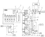
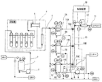
以下、本発明について図面に基づいて詳細に説明する。図1及び図2は、本発明の一実施形態による蒸留水供給システムを示すフロー図である。
図1及び図2において、1は蒸留器原水タンクであり、液量計(LSA)により所定の範囲で純水が供給される。蒸留器原水タンク1は、途中に蒸留器給水ポンプ2が設けられた第1の給水管3を経由して蒸留器4に連通している。蒸留器4は、5段の蒸留槽4A〜4Eと集水管5とを備え、集水管5は、第2の給水管6に連続しており、分岐して第1〜第3の蒸留水タンク7A,7B,7Cに連通している。
Hereinafter, the present invention will be described in detail with reference to the drawings. 1 and 2 are flow diagrams illustrating a distilled water supply system according to an embodiment of the present invention.
1 and 2, reference numeral 1 denotes a distiller raw water tank, which is supplied with pure water within a predetermined range by a liquid meter (LSA). The distiller raw water tank 1 communicates with the distiller 4 via a first
第1〜第3の蒸留水タンク7A,7B,7Cには、それぞれ液量指示警報装置(LIA)と圧力指示警報装置(PIA)と蒸留水温度計測警報装置(TRA)とが付設され、さらに底部には蒸留水供給路8A,8B,8Cが取り付けられていて、これら蒸留水供給路8A,8B,8Cは合流して蒸留水供給路8となり、供給手段たる蒸留水ポンプ9を経由して、医薬品製造ラインなどのユースポイント(UP)に続いている。なお、蒸留水ポンプ9は、可変電圧可変周波数インバータ(VVVF)により制御されている。
Each of the first to third distilled
一方、11はユースポイント(UP)からの返送路であり、この返送路11の途中には蒸気による熱交換器である蒸留水加熱器12が設けられていて、該蒸留水加熱器12を経由した後、主管路13が分岐管路14A,14B,14Cとブロー手段たるブロー排管15とに分岐し、分岐管路14A,14B,14Cがそれぞれ第1〜第3の蒸留水タンク7A,7B,7Cに連通している。なお、これら分岐管路14A,14B,14Cとブロー排管15とには、それぞれ自動制御弁16A,16B,16Cとブロー排管開閉弁17とが設けられている。
On the other hand,
このような蒸留水供給システムにおいて、返送路11には蒸留水加熱器12の上流側(前側)に温度計測警報装置(TRA)が、下流側(後側)に温度指示制御警報装置(TICA)がそれぞれ設けられている。また、蒸留水加熱器12には、返送路11内を流れる返送蒸留水の圧力を検知する圧力センサ(図示せず)と蒸気圧を検知する圧力センサ(図示せず)とが設けられていて、これらセンサは圧力を管理する圧力計測手段たる圧力指示警報装置(PICA)に接続している。さらに、返送路11の蒸留水加熱器12の下流側である主管路13には、蒸留水導電率計測手段たる蒸留水導電率計測警報装置(CRA)が取付けられている。
In such a distilled water supply system, the
そして、これら温度指示制御警報装置(TICA)、圧力指示警報装置(PICA)、蒸留水導電率計測警報装置(CRA)、可変電圧可変周波数インバータ(VVVF)並びに自動制御弁16A,16B,16C及びブロー排管開閉弁17は、制御装置18により制御可能となっている。なお、図1及び図2中○印はバルブ、弁などの開閉機構を、破線は排出経路を示している。
These temperature indication control alarm device (TICA), pressure indication alarm device (PICA), distilled water conductivity measurement alarm device (CRA), variable voltage variable frequency inverter (VVVF) and
前記構成につきその作用について説明する。まず、蒸留水の供給プロセスにおいては、図1に示すように、図示しない純水製造装置で製造された純水を蒸留水原水タンク1に供給し、純水が蒸留水原水タンク1に所定量貯留されたら、蒸留器給水ポンプ2を稼動して第1の給水管3を介して蒸留器4に純水を送り、蒸留器4により蒸留水が生成される。この蒸留水は、集水管5及び第2の給水管6を通って第1〜第3の蒸留水タンク7A,7B,7Cに貯留される。このとき蒸留水の温度が80℃以上であることを蒸留水温度計測警報装置(TRA)により確認するとともに、第1〜第3の蒸留水タンク7A,7B,7Cに所定量の蒸留水が貯留されていることを液量指示警報装置(LIA)及び圧力指示警報装置(PIA)にて確認する。
The effect | action is demonstrated about the said structure. First, in the process of supplying distilled water, as shown in FIG. 1, pure water produced by a pure water production apparatus (not shown) is supplied to the distilled water raw water tank 1, and the pure water is supplied to the distilled water raw water tank 1 by a predetermined amount. Once stored, the distiller
その後、蒸留水ポンプ9を稼動することにより、蒸留水供給路8A,8B,8C及び8からユースポイント(UP)に蒸留水が供給される。このとき蒸留水ポンプ9の送水量は、ユースポイント(UP)における蒸留水消費量や返送量等に応じて可変電圧可変周波数インバータ(VVVF)により制御されている。そして、ユースポイント(UP)においては、注射液、輸液、薬液等の製造ラインとして必要量の蒸留水が使用される。
Thereafter, by operating the distilled
次に、返送プロセスにおいて、ユースポイント(UP)で消費されなかった蒸留水は、返送路11から返送されるが、この返送蒸留水は、その温度が第1〜第3の蒸留水タンク7A,7B,7Cを出たときよりも当然低下しているので、これをそのまま蒸留水タンク7A,7B,7Cに返送したのでは該タンク内の蒸留水の温度の低下をきたすばかりか滅菌性においても不都合である。そこで、返送路11の途中に設けられた、蒸気との熱交換による蒸留水加熱器12により、80℃以上、例えば83℃以上に加熱された上で主管路13を経て分岐管路14A,14B,14Cより第1〜第3の蒸留水タンク7A,7B,7Cに返送される。この返送蒸留水の蒸気加熱後の温度は、蒸留水加熱器12の下流側で温度指示制御警報装置(TICA)により計測されることで確認される。なお、返送蒸留水の蒸気加熱前の温度も、蒸留水加熱器12の上流側で温度計測警報装置(TRA)により計測される。
Next, in the return process, distilled water that has not been consumed at the use point (UP) is returned from the
このとき、蒸留水加熱器12には、返送路11内を流れる返送蒸留水の圧力を検知する圧力センサ(図示せず)と蒸気圧を検知する圧力センサ(図示せず)とが設けられていて、これらセンサは圧力を管理する圧力指示警報装置(PICA)に接続されており、通常、万一蒸留水加熱器12の配管に破損等が生じたとしても、返送蒸留水が汚染されないように返送蒸留水の圧力を加熱用蒸気圧よりも高く設定していることから、圧力指示警報装置(PICA)の指示値(返送蒸留水の圧力−加熱用蒸気圧)が0よりも大きいことを確認した上で、制御装置18は返送を行うように制御する。すなわち、自動制御弁16A,16B,16Cは開成しており、ブロー排管開閉弁17は閉鎖するように制御装置18により制御されている(図1)。
At this time, the distilled
一方、蒸留水加熱器12の配管の破損が拡大すると、返送蒸留水の圧力が減少するので圧力指示警報装置(PICA)の計測データにおける差圧(返送蒸留水の圧力−加熱用蒸気圧)が減少し、最悪の場合には0以下となる。この時点で加熱用蒸気が返送蒸留水側に混入し返送蒸留水の汚染が起こる。このような汚染された返送蒸留水をそのまま第1〜第3の蒸留水タンク7A,7B,7Cに返送してしまうと、蒸留水タンク7A,7B,7C内の蒸留水全体が汚染されてしまい、蒸留水の供給自体を停止しなければならなくなる。そこで、本実施形態においては、圧力指示警報装置(PICA)の指示値(返送蒸留水の圧力−加熱用蒸気圧)が0以下となったことを確認したら、制御装置18は返送路11を第1〜第3の蒸留水タンク7A,7B,7C側からブロー手段側に切り替えるとともに圧力指示警報装置(PICA)が警報を発して異常を知らせるように制御する。すなわち、制御装置18は、自動制御弁16A,16B,16Cを閉鎖して、ブロー排管開閉弁17を開成するように制御し、返送蒸留水をブローする(図2)。このような制御を行うことにより、第1〜第3の蒸留水タンク7A,7B,7Cに直結している分岐管路14A,14B,14Cに汚染された水が混入することを防止することができるとともに、既に汚染されている返送路11及び主管路13内の返送蒸留水を系外に排出することができるので、蒸留水タンク7A,7B,7Cに貯留してある蒸留水を汚染することがなく、しかも警報により蒸留水加熱器12のリークに対し確実かつ迅速に対応することが可能となる。
On the other hand, when the damage to the piping of the distilled
しかも、本実施態様においては、蒸留水加熱器12の直後の主管路13に蒸留水導電率計測警報装置(CRA)を設け、返送蒸留水の導電率を計測しており、これにより返送蒸留水の導電率が所定の値以上、例えば、1μS/cm以上になったら、蒸留水としての再利用に不適当であると判断して、制御装置18は、自動制御弁16A,16B,16Cを閉鎖して、ブロー排管開閉弁17を開成するように制御し、返送蒸留水をブローするとともに、蒸留水導電率計測警報装置(CRA)が警報を発することにより異常を知らせる。このような制御を行うことにより、蒸留水加熱器12のリーク以外の原因による返送蒸留水の汚染を該返送蒸留水の導電率によって監視することで、第1〜第3の蒸留水タンク7A,7B,7Cに汚染された返送蒸留水が返送されるのをより確実に防止することができるようになっている。
In addition, in this embodiment, a distilled water conductivity measurement alarm device (CRA) is provided in the
以上、本発明の一実施形態について、添付図面を参照して詳細に説明したが、本発明は前記実施形態に限定されるものではなく、本発明の思想の範囲内で種々の変形実施が可能である。すなわち、熱交換器の蒸気側の圧力と返送蒸留水の圧力との差圧を監視し、0以下となったら返送蒸留水をブローにより排出する構成であれば、その他の制御については種々の変更が可能であることについてはいうまでもない。 As mentioned above, although one Embodiment of this invention was described in detail with reference to the accompanying drawing, this invention is not limited to the said embodiment, A various deformation | transformation implementation is possible within the range of the thought of this invention. It is. That is, if the differential pressure between the pressure on the steam side of the heat exchanger and the pressure of the return distilled water is monitored and the return distilled water is discharged by blow when it becomes 0 or less, various changes are made for other controls. Needless to say that is possible.
4…蒸留器
7A,7B,7C…第1〜第3の蒸留水タンク
11…返送路
12…蒸留水加熱器(熱交換器)
13…主管路(返送路)
14A,14B,14C…分岐管路(返送路)
15…ブロー排管(ブロー手段)
18…制御装置
UP…ユースポイント
PICA…圧力指示警報装置(圧力計測手段、警報装置)
CRA…蒸留水導電率計測警報装置(蒸留水導電率測定手段、警報装置)
4 ...
13 ... Main pipeline (return route)
14A, 14B, 14C ... Branch pipe (return path)
15 ... Blow exhaust pipe (blow means)
18 ... Control device UP ... Use point PICA ... Pressure indication alarm device (pressure measuring means, alarm device)
CRA: Distilled water conductivity measurement alarm device (distilled water conductivity measurement means, alarm device)
Claims (4)
前記熱交換器の返送蒸留水側及び蒸気側の差圧を検知する圧力計測手段と、
前記返送路に前記蒸留水タンクと切り替え可能に設けられたブロー手段と、
前記圧力計測手段のデータに基づき前記ブロー手段を制御する制御装置とを有し、
前記返送蒸留水側の圧力を蒸気側の圧力よりも高く設定して運転することにより、前記制御手段は、前記圧力計測手段のデータで前記熱交換器の蒸気側の圧力が返送蒸留水の圧力以上となったら前記返送路を蒸留水タンク側からブロー手段側に切り替えることを特徴とする蒸留水供給システム。 A distilled water tank for storing distilled water purified by a distiller, supply means for supplying distilled water from the distilled water tank to a use point, and returning the remaining distilled water used at the use point to the distilled water tank A distilled water supply system comprising a return path and a heat exchanger that is provided in the middle of the return path and heats the return distilled water with steam,
Pressure measuring means for detecting a differential pressure between the return distilled water side and the steam side of the heat exchanger;
Blow means provided in the return path to be switchable with the distilled water tank;
A control device for controlling the blowing means based on the data of the pressure measuring means,
By operating by setting the pressure on the return distilled water side higher than the pressure on the steam side, the control means uses the data of the pressure measuring means so that the pressure on the steam side of the heat exchanger is the pressure of the return distilled water. If it becomes above, the said return path will be switched from the distilled water tank side to the blow means side, The distilled water supply system characterized by the above-mentioned.
前記制御手段は、前記圧力計測手段のデータで前記熱交換器の蒸気側の圧力が返送蒸留水の圧力以上となったら前記警報装置を作動して警報を発するように制御することを特徴とする請求項1に記載の蒸留水供給システム。 An alarm device is connected to the control means;
The control means performs control so that an alarm is generated by operating the alarm device when the pressure on the steam side of the heat exchanger becomes equal to or higher than the pressure of return distilled water in the data of the pressure measuring means. The distilled water supply system according to claim 1.
前記制御手段は、前記蒸留水導電率計測手段のデータにおいて前記返送蒸留水の導電率が所定の値を上回ったら前記返送路を蒸留水タンク側からブロー手段側に切り替えることを特徴とする請求項1又は2に記載の蒸留水供給システム。 Distilled water conductivity measuring means connected to the control means is provided downstream from the heat exchanger of the return path,
The control means switches the return path from the distilled water tank side to the blow means side when the conductivity of the return distilled water exceeds a predetermined value in the data of the distilled water conductivity measuring means. The distilled water supply system according to 1 or 2.
前記制御手段は、前記蒸留水導電率計測手段のデータにおいて前記蒸留水導電率が所定の値を上回ったら前記警報装置を作動して警報を発するように制御することを特徴とする請求項3に記載の蒸留水供給システム。
An alarm device is connected to the control means;
4. The control unit according to claim 3, wherein when the distilled water conductivity exceeds a predetermined value in the data of the distilled water conductivity measuring unit, the control unit controls the alarm device to operate to issue an alarm. The distilled water supply system described.
Priority Applications (1)
| Application Number | Priority Date | Filing Date | Title |
|---|---|---|---|
| JP2005246234A JP2007054792A (en) | 2005-08-26 | 2005-08-26 | Distilled water supply system |
Applications Claiming Priority (1)
| Application Number | Priority Date | Filing Date | Title |
|---|---|---|---|
| JP2005246234A JP2007054792A (en) | 2005-08-26 | 2005-08-26 | Distilled water supply system |
Publications (1)
| Publication Number | Publication Date |
|---|---|
| JP2007054792A true JP2007054792A (en) | 2007-03-08 |
Family
ID=37918726
Family Applications (1)
| Application Number | Title | Priority Date | Filing Date |
|---|---|---|---|
| JP2005246234A Pending JP2007054792A (en) | 2005-08-26 | 2005-08-26 | Distilled water supply system |
Country Status (1)
| Country | Link |
|---|---|
| JP (1) | JP2007054792A (en) |
-
2005
- 2005-08-26 JP JP2005246234A patent/JP2007054792A/en active Pending
Similar Documents
| Publication | Publication Date | Title |
|---|---|---|
| EP2414722B1 (en) | Programmable steam trap apparatus | |
| AU2014268694B2 (en) | Thermal control system | |
| US20090288562A1 (en) | Beverage maker flow detection logic | |
| JP6489423B2 (en) | Process test device and steam sterilizer equipped with the same | |
| CN213551217U (en) | Pipeline machine with preheating water tank | |
| CN105973653B (en) | Pure steam on-line sampling circulation device and method | |
| JP2007054792A (en) | Distilled water supply system | |
| JP5786417B2 (en) | Cleaning device | |
| JP6563525B2 (en) | Device for providing sterile water for injection | |
| KR200450742Y1 (en) | Carburetor monitoring device | |
| CN110077746B (en) | Liquid storage tank pressure maintaining device and method | |
| SE465654B (en) | DEVICE FOR THE PREPARATION OF STERILE AIR | |
| CN113154666A (en) | Integrated mold temperature control system | |
| TWI901764B (en) | Management device for vacuum evaporation water generator | |
| JP2007255838A (en) | Boiler equipment | |
| JP6555477B2 (en) | Air leak detector and steam sterilizer equipped with the same | |
| JP2010137874A (en) | Beverage dispenser | |
| JP6738559B2 (en) | Air leak detector and steam sterilizer equipped with it | |
| JP6642958B2 (en) | Heat exchange system and method for cleaning heat exchanger | |
| JP2009120251A (en) | How to prevent chemical solution or cleaning water from entering the nozzle cover | |
| KR100683886B1 (en) | Hot and cold water heater control method | |
| CN204987467U (en) | A new type of heating kettle | |
| CN109601812B (en) | A vacuum cooling system | |
| CN209989128U (en) | A water detection device for medicinal pure water | |
| JP3928886B2 (en) | Method and apparatus for detecting liquid leakage panel in open rack type LNG vaporizer |