JP2007041530A - Endless belt and image forming apparatus using the same - Google Patents
Endless belt and image forming apparatus using the same Download PDFInfo
- Publication number
- JP2007041530A JP2007041530A JP2006126629A JP2006126629A JP2007041530A JP 2007041530 A JP2007041530 A JP 2007041530A JP 2006126629 A JP2006126629 A JP 2006126629A JP 2006126629 A JP2006126629 A JP 2006126629A JP 2007041530 A JP2007041530 A JP 2007041530A
- Authority
- JP
- Japan
- Prior art keywords
- belt
- prevention guide
- meandering prevention
- meandering
- endless belt
- Prior art date
- Legal status (The legal status is an assumption and is not a legal conclusion. Google has not performed a legal analysis and makes no representation as to the accuracy of the status listed.)
- Pending
Links
Images


Abstract
Description
本発明は、複写機やプリンタ等の電子写真方式を用いた画像形成装置に用いられるエンドレスベルトおよびそれを用いた画像形成装置に関する。更に詳しくは、蛇行防止用のガイドを有し、長期間安定走行可能な蛇行防止ガイド付エンドレスベルトおよびそれを用いた画像形成装置に関する。 The present invention relates to an endless belt used in an image forming apparatus using an electrophotographic system such as a copying machine or a printer, and an image forming apparatus using the same. More specifically, the present invention relates to an endless belt with a meandering prevention guide having a meandering prevention guide and capable of stable running for a long period of time, and an image forming apparatus using the same.
電子写真方式を用いた画像形成装置としては、例えば、中間転写ベルトを使用した中間転写方式のカラー画像形成装置がある。これは、電子写真プロセス等によりトナー像が形成される像担持体(例えば感光体ドラム)の転写部で接触して回転するような中間転写ベルトを複数のベルト支持ロール間に張架して配設したものであり、その像担持体上に形成される複数のトナー像を一旦中間転写ベルトの同じ位置に重ねあわせるように一次転写した後、その中間転写ベルト上に転写されたトナー像を用紙に一括して転写するものである。そして、用紙上に転写された多重のトナー像は、その後定着装置により定着されてカラー画像となる。 As an image forming apparatus using an electrophotographic system, for example, there is an intermediate transfer type color image forming apparatus using an intermediate transfer belt. This is because an intermediate transfer belt that rotates in contact with a transfer portion of an image carrier (for example, a photosensitive drum) on which a toner image is formed by an electrophotographic process is stretched between a plurality of belt support rolls. The plurality of toner images formed on the image carrier are primarily transferred so as to overlap each other at the same position on the intermediate transfer belt, and then the toner image transferred onto the intermediate transfer belt is transferred to a sheet of paper. Are collectively transferred. The multiple toner images transferred onto the paper are then fixed by a fixing device to form a color image.
この他、エンドレスベルトを備えた画像形成装置としては、用紙を担持して複数の画像形成ユニットの転写部を通過させるように搬送する用紙搬送ベルトを使用した、いわゆるタンデムタイプのカラー画像形成装置もある。これは、各色成分のトナー像を個々に形成するため画像形成ユニットを複数並べて配置し、その各画像形成ユニットの転写部で接触して回転するように用紙搬送ベルトを複数のベルト支持ロール間に張架して配設したものであり、その用紙搬送ベルトに吸着して担持した用紙を各画像形成ユニットの転写部を通過させるように搬送することにより、各画像形成ユニットで形成される各トナー像を同じ用紙に順次重ねあわせるように転写し、最後に定着させてカラー画像とするものである。 In addition, as an image forming apparatus provided with an endless belt, there is also a so-called tandem type color image forming apparatus that uses a sheet conveying belt that carries a sheet and conveys it through a transfer portion of a plurality of image forming units. is there. This is because a plurality of image forming units are arranged side by side in order to individually form toner images of each color component, and the sheet conveying belt is placed between a plurality of belt support rolls so as to rotate in contact with the transfer portion of each image forming unit. Each toner formed in each image forming unit by being stretched and transporting the paper adsorbed and supported by the paper transport belt so as to pass through the transfer portion of each image forming unit The image is transferred onto the same sheet in order to be superimposed, and finally fixed to form a color image.
ところで、このような中間転写ベルトや用紙搬送ベルト等のエンドレスベルトを使用したカラー画像形成装置では、そのエンドレスベルトを張架支持する複数のベルト支持ロールの回転軸の平行度やロール外径がばらつくことや、そのエンドレスベルト自体の周長変化により張力が不均一となること等が原因となって、エンドレスベルトが直進走行せず、ベルト支持ロールの軸方向に変位した状態で走行する、いわゆる片寄り走行や蛇行が発生することがある。このため、そのエンドレスベルトに直接又はエンドレスベルトに担持された用紙に順次転写される各トナー像の位置がずれてしまうことがあり、この場合には、最終的には用紙上に形成されるカラー画像に色ずれや色相変化等がおこる画像欠陥が発生するという不具合がある。 By the way, in such a color image forming apparatus using an endless belt such as an intermediate transfer belt or a paper transport belt, the parallelism of the rotation shafts of the plurality of belt support rolls that support the endless belt and the outer diameter of the roll vary. In other words, the endless belt does not travel straight but travels in a state displaced in the axial direction of the belt support roll because the tension becomes uneven due to the change in the circumference of the endless belt itself. Sideways running and meandering may occur. For this reason, the position of each toner image that is sequentially transferred to the endless belt or sequentially to the paper carried on the endless belt may be displaced. In this case, the color formed on the paper in the end There is a problem that an image defect in which a color shift or a hue change occurs in an image occurs.
一方、従来のガイド付きシームレスベルトは、図示しないが、エンドレスに形成されたシームレスベルトの内周面の開口両端部側に、弾性帯体からなる蛇行規制ガイドが周方向に向けてそれぞれ接着され、各蛇行規制ガイドの両端面が突き合わせて接着されている。各蛇行規制ガイドの端面は、周方向、長手方向に対して垂直にカットされている。 On the other hand, the conventional seamless belt with a guide is not shown, but the meandering regulation guide made of an elastic band is adhered to the both ends of the inner peripheral surface of the seamless belt formed endlessly in the circumferential direction. Both end surfaces of each meandering regulation guide are abutted and bonded. The end face of each meandering regulation guide is cut perpendicular to the circumferential direction and the longitudinal direction.
従来のガイド付きシームレスベルトは、以上のように構成されているので、ロール部分で繰り返し屈曲されると、蛇行規制ガイドの両端面、すなわち継目に応力が集中し、蛇行規制ガイドの剥がれが発生するおそれがある。画像形成装置の小サイズ化に伴い、小径のロールを用いる傾向にあり、更に、蛇行規制ガイドの両端面の継目に応力が集中する傾向にある。このような問題を解消する手段としては、蛇行規制ガイドに補強材を設ける方法(例えば特許文献1参照)、蛇行規制ガイドの継目に接着剤を設ける方法(例えば、特許文献1及び2参照)、継目のない蛇行規制ガイドを使用する方法があげられる。
しかしながら、蛇行規制ガイドの継目に補強材を設ける方法では、更に部品を増やすこととなり、蛇行規制ガイドの継目に接着剤を設ける方法では、接着の工程増加を招くし、継目のない蛇行規制ガイドを使用する方法では、シームレスベルトと蛇行規制ガイドの寸法を高精度に合わせる必要があるが、材料の硬化収縮や熱収縮等が生じるので、位置合わせが非常に困難である。
Since the conventional seamless belt with guide is configured as described above, when the roll portion is repeatedly bent, stress concentrates on both end surfaces of the meandering restriction guide, that is, the seam, and the meandering restriction guide peels off. There is a fear. Along with the downsizing of the image forming apparatus, there is a tendency to use a roll having a small diameter, and further, stress tends to be concentrated at the joints of both end faces of the meandering regulation guide. As means for solving such a problem, a method of providing a reinforcing material in the meandering regulation guide (see, for example, Patent Document 1), a method of providing an adhesive in the joint of the meandering regulation guide (see, for example,
However, in the method of providing the reinforcing material at the joint of the meandering regulation guide, the number of parts is further increased, and in the method of providing the adhesive at the joint of the meandering regulation guide, the bonding process is increased, and a seamless meandering regulation guide is provided. In the method to be used, it is necessary to match the dimensions of the seamless belt and the meandering regulation guide with high accuracy. However, since the material undergoes shrinkage due to curing or heat shrinkage, alignment is very difficult.
エンドレスに形成されたシームレスベルトの弾性帯体からなる蛇行規制ガイドの相対向する両端面を周方向に対し所定の角度でそれぞれ斜めに形成することで、製造工程や部品点数の増加を招くことなく、蛇行規制ガイドの継目からの破断を簡易な方法で抑制できる(例えば特許文献3参照)。しかしながら、所定の角度でそれぞれ斜めに形成した場合には、蛇行規制ガイドの斜めに形成した再先端においては、ガイド幅が細くなり、そこに応力が集中した場合には、耐久性に大きな影響がある。
本発明は、前記事情に鑑みてなされたものであり、以下の内容を課題とする。即ち、片寄り走行や蛇行を、ベルトの寿命低下を招くことなく長期にわたって簡単、確実に防止することができる、蛇行防止ガイドを備えたエンドレスベルトを提供することを課題とする。更に、前記エンドレスベルトの片寄り走行や蛇行を、ベルトの寿命低下を招くことなく長期にわたって簡単、確実に防止する蛇行防止ガイドを備えたエンドレスベルトを用い、信頼性が向上し、小型化が可能な画像形成装置を提供することを課題とする。 This invention is made | formed in view of the said situation, and makes the following content a subject. That is, it is an object of the present invention to provide an endless belt provided with a meandering prevention guide that can easily and reliably prevent a deviated running or meandering over a long period of time without causing a reduction in the life of the belt. Furthermore, using an endless belt with a meandering prevention guide that easily and reliably prevents the endless belt from running or meandering for a long time without deteriorating the life of the belt, reliability is improved and downsizing is possible. It is an object to provide a simple image forming apparatus.
上記課題は、以下の手段により解決される。
即ち、本発明は、
<1> エンドレスに形成された樹脂製のベルト本体の幅方向の少なくとも片側の側縁に沿って、帯状の蛇行防止ガイドを該ベルト本体に接着させたエンドレスベルトであって、前記蛇行防止ガイドには、該蛇行防止ガイドの長手方向の一端に厚み方向から見た凸部と、該蛇行防止ガイドの長手方向の他端に該凸部に対応する凹部とが設けてあり、該凸部と凹部とが接合部を介して向き合っており、前記凸部の先端の面の該蛇行防止ガイドの幅方向の長さが、該蛇行防止ガイドの幅の20〜50%であることを特徴とするエンドレスベルトである。
The above problem is solved by the following means.
That is, the present invention
<1> An endless belt in which a belt-like meandering prevention guide is bonded to the belt body along at least one side edge in the width direction of the resin belt body formed on the endless, Is provided with a convex portion viewed from the thickness direction at one end in the longitudinal direction of the meandering prevention guide, and a concave portion corresponding to the convex portion at the other end in the longitudinal direction of the meandering prevention guide. Are opposed to each other through a joint portion, and the length in the width direction of the meandering prevention guide of the front end surface of the convex portion is 20 to 50% of the width of the meandering prevention guide. It is a belt.
前記蛇行防止ガイドの前記ベルト本体の周方向両端部に、該両端部を接着部を介して接合した際に、それぞれが噛み合う凸部及び凹部を設けることにより、接着部に作用するストレスを分散させることができ、前記ベルト本体からの蛇行防止ガイドの剥離を防止できる。更に、前記凸部の先端の面の幅が、該蛇行防止ガイドの幅の20〜50%であることにより、凸部の先端に集中するストレスを分散させることができる。 Distributing stress acting on the adhesive portion by providing a convex portion and a concave portion that mesh with each other when the both end portions are joined to each other in the circumferential direction of the belt body of the meandering prevention guide via the adhesive portion. The meandering prevention guide can be prevented from peeling off from the belt body. Furthermore, when the width of the surface of the tip of the convex portion is 20 to 50% of the width of the meandering prevention guide, stress concentrated on the tip of the convex portion can be dispersed.
<2> 前記凸部が、蛇行防止ガイドの長手方向の一端の前記ベルト本体の幅方向端部に設けられていることを特徴とする<1>に記載のエンドレスベルトである。
<3> 前記凸部の先端が、他端の前記凹部の凹部以外の部分と重なる部分の長さが、前記蛇行防止ガイドの幅の40〜80%であることを特徴とする<1>又は<2>に記載のエンドレスベルトである。
<2> The endless belt according to <1>, wherein the convex portion is provided at an end in the width direction of the belt main body at one end in the longitudinal direction of the meandering prevention guide.
<3> The length of the portion where the tip of the convex portion overlaps with the portion other than the concave portion of the concave portion at the other end is 40 to 80% of the width of the meandering prevention guide <1> or It is an endless belt as described in <2>.
<4> 前記凸部が、該凸部の先端の面に向かって幅が減少していることを特徴とする<1>〜<3>の何れか1つに記載のエンドレスベルトである。
<5> 前記凸部の先端の面の、前記ベルト本体の幅方向端部側が、円弧状の曲線であることを特徴とする<1>〜<4>の何れか1つに記載のエンドレスベルトである。
<4> The endless belt according to any one of <1> to <3>, wherein a width of the convex portion decreases toward a front end surface of the convex portion.
<5> The endless belt according to any one of <1> to <4>, wherein a width direction end portion side of the belt main body of the front end surface of the convex portion is an arcuate curve. It is.
<6> 前記ベルト本体と前記蛇行防止ガイドとが、弾性接着剤で接着されてなることを特徴とする<1>〜<5>の何れか1つに記載のエンドレスベルトである。
<7> 前記ベルト本体と前記蛇行防止ガイドとが、感熱型シート形状の接着剤で形成されてなることを特徴とする<1>〜<6>の何れか1つに記載のエンドレスベルトである。
<6> The endless belt according to any one of <1> to <5>, wherein the belt body and the meandering prevention guide are bonded with an elastic adhesive.
<7> The endless belt according to any one of <1> to <6>, wherein the belt body and the meandering prevention guide are formed of a heat-sensitive sheet-shaped adhesive. .
<8> <1>〜<7>の何れか1つに記載のエンドレスベルトが、複数の支持ロールにより回転可能に支持されて備えられていることを特徴とする画像形成装置である。
<9> 前記複数の支持ロールの少なくとも1つが、外径が14〜20mmである支持ロールであることを特徴とする<8>に記載の画像形成装置である。
<10> 前記エンドレスベルトが、略鉛直方向に配置された複数のユニットに接するように備えられていることを特徴とする<8>又は<9>に記載の画像形成装置である。
<8> An image forming apparatus, wherein the endless belt according to any one of <1> to <7> is rotatably supported by a plurality of support rolls.
<9> The image forming apparatus according to <8>, wherein at least one of the plurality of support rolls is a support roll having an outer diameter of 14 to 20 mm.
<10> The image forming apparatus according to <8> or <9>, wherein the endless belt is provided in contact with a plurality of units arranged in a substantially vertical direction.
本発明は、片寄り走行や蛇行を、ベルトの寿命低下を招くことなく長期にわたって簡単、確実に防止することができる、蛇行防止ガイドを備えたエンドレスベルトを提供することができる。更に、前記エンドレスベルトの片寄り走行や蛇行を、ベルトの寿命低下を招くことなく長期にわたって簡単、確実に防止する蛇行防止ガイドを備えたエンドレスベルトを用い、信頼性が向上し、小型化が可能な画像形成装置を提供することができる。 The present invention can provide an endless belt provided with a meandering prevention guide that can easily and reliably prevent shifting and meandering for a long time without deteriorating the life of the belt. Furthermore, using an endless belt with a meandering prevention guide that easily and reliably prevents the endless belt from running or meandering for a long time without deteriorating the life of the belt, reliability is improved and downsizing is possible. Image forming apparatus can be provided.
<エンドレスベルト>
本発明のエンドレスベルトは、エンドレスに形成された樹脂製のベルト本体の幅方向の少なくとも片側の側縁に沿って、帯状の蛇行防止ガイドを該ベルト本体に接着させたエンドレスベルトであって、前記蛇行防止ガイドには、該蛇行防止ガイドの長手方向の一端に厚み方向から見た凸部と、該蛇行防止ガイドの長手方向の他端に該凸部に対応する凹部とが設けてあり、該凸部と凹部とが接合部を介して向き合うように接合され、前記凸部の先端の面の該蛇行防止ガイドの幅方向の長さが、該蛇行防止ガイドの幅の20〜50%であることを特徴とする。
<Endless belt>
The endless belt of the present invention is an endless belt in which a belt-like meandering prevention guide is bonded to the belt body along at least one side edge in the width direction of the resin-made belt body formed endlessly. The meander prevention guide is provided with a convex portion viewed from the thickness direction at one end in the longitudinal direction of the meander prevention guide, and a concave portion corresponding to the convex portion at the other end in the longitudinal direction of the meander prevention guide, The convex part and the concave part are joined so as to face each other through the joint part, and the length in the width direction of the meandering prevention guide of the surface of the tip of the convex part is 20 to 50% of the width of the meandering prevention guide. It is characterized by that.
以下、図面を参照して本発明のエンドレスベルトを詳細に説明する。
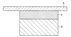
図1に示すように、本発明のエンドレスベルト1は、エンドレスに形成された樹脂製のベルト本体2の幅方向の少なくとも片側の側縁に沿って、帯状の蛇行防止ガイド3をベルト本体2に接着させたエンドレスベルトである。蛇行防止ガイド3の詳細については後述する。本発明のエンドレスベルト1は、蛇行防止ガイド3がベルト本体2の内周面に設けられていることが好ましい。
また、図2に示すように、本発明のエンドレスベルト1は、蛇行防止ガイド3が感熱型シート形状の接着剤(感熱性接着剤シート)4を介して、ベルト本体2に接着固定されていることが好ましい。また、蛇行防止ガイド3が弾性接着剤からなる層を介して、ベルト本体2に接着固定されていることも好ましい。
Hereinafter, the endless belt of the present invention will be described in detail with reference to the drawings.
As shown in FIG. 1, an
As shown in FIG. 2, in the
本発明のエンドレスベルト1は、後述する画像形成装置に、複数の支持ロールにより回転可能に支持されて備ることができ、ベルト本体2の外周面が、トナー像が転写される用紙を担持する用紙担持面、又はトナー像が形成されるトナー像担持面等である、樹脂製のエンドレスベルトであって、電子写真式複写機、レーザープリンター等における感光装置、中間転写装置、転写分離装置、搬送装置、帯電装置、現像装置等に好適に使用される。ここで、本発明のエンドレスベルトを構成するベルト本体は、エンドレスベルトの用途、機能等に応じて、材質、形状、大きさ等が適宜設定される。
The
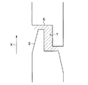
後述する画像形成装置において、本発明のエンドレスベルトであるエンドレスベルト1は、図3に示すような蛇行防止ガイド3を沿わせる(規制する)ための、溝20が設けてある支持ロール21により張架されることが好ましい。この際、本発明のエンドレスベルト1における蛇行防止ガイド3を、溝20に沿わせて規制することにより、エンドレスベルト1の片寄り走行や蛇行を防止することができる。尚、図3の(A)は、溝20が設けてある支持ロール21を示すための斜視図であり、図3の(B)は、図3の(A)の溝20が設けてある支持ロール21を、支持ロール21の面で切断したときの要部拡大断面図である。
また、エンドレスベルト1は、図3(C)に示すように、ベルト支持ロール21の側縁部に当接するように張架されることも好ましい。この場合、蛇行防止ガイド3がベルト支持ロールの側端部により規制されることにより、エンドレスベルト1の片寄り走行や蛇行を防止することができる。
In an image forming apparatus to be described later, an
Further, the
−ベルト本体−
ベルト本体2の材質としては、ポリイミド系樹脂、ポリアミドイミド系樹脂、ポリエステル系樹脂、ポリウレタン系樹脂、ポリアミド系樹脂、フッ素系樹脂等が挙げられる。なお、ベルト本体はつなぎ目があってもなくてもよい。ベルト本体の厚さは、通常、0.02〜0.2mm程度が好ましい。
ベルト本体2の一例を挙げると、電子写真方式を用いた画像形成装置等における中間転写ベルト及び転写搬送ベルトの場合、導電剤を含有するポリイミド系樹脂からなる半導電性ベルト等が使用される。ベルト本体2の材料は、例えば、ポリアミドイミド樹脂として、東洋紡バイロマックスHR16NN(固形分18質量%)を好適に用いることができる。
-Belt body-
Examples of the material of the
As an example of the belt
また、エンドレスベルトを中間転写ベルト、転写搬送ベルトとして用いる場合、1×10⁹Ω/□〜1×1014Ω/□の範囲に表面抵抗率を制御するために、必要に応じて導電性フィラーとして、カーボンブラック、グラファイト、アルミニウム、銅合金などの金属または合金、酸化スズ、酸化亜鉛、チタン酸カリム、酸化スズ−酸化インジウムまたは酸化スズ−酸化アンチモン複合酸化物などの金属酸化物、または、ポリアニリンなどの導電性ポリマーなどが単独又は2種以上の併用により用いられる。中でも、導電性フィラーとしては、コストの点でカーボンブラックが好適である。また、必要に応じて分散剤、滑剤などの加工助剤を添加することができる。
ここで、表面抵抗率は、(株)ダイヤインスツルメント製ハイレスタUPMCP−450型URプローブを用いて、22℃、55%RHの環境下で測定し、JIS K 6911に従い測定した。ベルトの24点(幅方向3箇所×周方向8箇所)を測定し、その平均値をベルトの表面抵抗率とした。
Further, when the endless belt is used as an intermediate transfer belt or a transfer / conveying belt, a conductive filler is used as necessary in order to control the surface resistivity in the range of 1 × 10 9 Ω / □ to 1 × 10 14 Ω / □. Metal oxides such as carbon black, graphite, aluminum, copper alloys, metal oxides such as tin oxide, zinc oxide, kalim titanate, tin oxide-indium oxide or tin oxide-antimony oxide composite oxide, or polyaniline Conductive polymers such as are used alone or in combination of two or more. Among these, carbon black is preferable as the conductive filler in terms of cost. Moreover, processing aids, such as a dispersing agent and a lubricant, can be added as needed.
Here, the surface resistivity was measured in an environment of 22 ° C. and 55% RH using a Hiresta UPMCP-450 type UR probe manufactured by Dia Instruments Co., Ltd., and measured according to JIS K 6911. 24 points (3 places in the width direction × 8 places in the circumferential direction) of the belt were measured, and the average value was taken as the surface resistivity of the belt.
−蛇行防止ガイド−
蛇行防止ガイド3は、エンドレスに形成された樹脂製のベルト本体2の、幅方向の少なくとも片側の側縁に沿って、ベルト本体2に接着されており、蛇行防止ガイド3の長手方向の一端に厚み方向から見た凸部と、蛇行防止ガイド3の長手方向の他端に凸部に対応する凹部とが設けてあり、凸部と凹部とが接合部を介して向き合っており、凸部の先端の面の該蛇行防止ガイドの幅方向の長さが、該蛇行防止ガイドの幅の20〜50%であることを特徴とする。蛇行防止ガイドの形状は、重心に関して点対称であってもよく、点対称ではなくても構わない。凸部は、蛇行防止ガイドの端部に1ヵ所設けるのみならず、複数ヵ所設けても構わない。
尚、接合部は、凸部を設けた蛇行防止ガイド3の一端と、凹部を設けた蛇行防止ガイド3の他端が向き合っている箇所をいう。
-Meandering prevention guide-
The
In addition, a junction part says the location where the other end of the
本発明に係る凸部及びそれに対応する凹部を有することにより、エンドレスベルトが各種の画像形成装置のロール部分で繰り返し屈曲されても、一箇所に応力の集中するのを抑制することができる。更に、本発明に係る凸部の先端面の幅の比率が20〜50%であると、蛇行防止ガイドの端部に応力が集中した場合でも、端部から剥がれる問題が少ない。その結果、本発明のエンドレスベルトは、凸部と凹部とが接合部を介して向き合うように、蛇行防止ガイド3を接着することにより、片寄り走行や蛇行を、ベルトの寿命低下を招くことなく長期にわたって簡単、確実に防止することができる。
尚、凸部の先端面の一部が円弧状の曲線となっている場合、本発明に係る凸部の先端面の幅の比率は、最大幅を有する部分の長さを先端面の幅として計算した比率とする。また、一方の端部に複数の凸部が設けられている場合は、複数の凸部の先端の面の幅の合計を、本発明に係る凸部の先端面の幅として計算した比率とする。
By having the convex portion according to the present invention and the concave portion corresponding to the convex portion, even if the endless belt is repeatedly bent at the roll portion of various image forming apparatuses, it is possible to suppress the concentration of stress in one place. Furthermore, when the ratio of the width of the front end surface of the convex portion according to the present invention is 20 to 50%, even when stress concentrates on the end portion of the meandering prevention guide, there is little problem of peeling from the end portion. As a result, the endless belt according to the present invention adheres to the
In addition, when a part of the front end surface of the convex portion has an arcuate curve, the ratio of the width of the front end surface of the convex portion according to the present invention is the length of the portion having the maximum width as the width of the front end surface The calculated ratio. Further, when a plurality of convex portions are provided at one end portion, the sum of the widths of the front end surfaces of the plurality of convex portions is a ratio calculated as the width of the front end surface of the convex portion according to the present invention. .
本発明に係る凸部の先端面の幅の比率は、既述のように20〜50%であることを必須とし、35〜50%であることが好ましく、40〜49%であることがより好ましい。 The ratio of the width of the tip surface of the convex portion according to the present invention must be 20 to 50% as described above, preferably 35 to 50%, more preferably 40 to 49%. preferable.
本発明のエンドレスベルトは、接合部7において、凸部5と凹部6とが接着剤で接合されていてもよい。該接着剤として、後述する弾性接着剤が挙げられる。また、該接着剤を用いる部分は接合部7の全面でもよいが、接合部7のベルト本体2の幅方向端部(好ましくは、蛇行防止ガイド3の幅に対する、接合部7のベルト本体2の幅方向端部からの長さが20〜80%)のみに接着剤を用いて接合されていることが好ましい。
In the endless belt of the present invention, in the
蛇行防止ガイド3のベルト本体2の長手方向の一端に設けられた凸部は、蛇行防止ガイド3の幅に対する先端の面の幅の比率(以下、「本発明に係る凸部の先端面の幅の比率」ということがある。)が、20〜50%であれば、特に限定されないが、図4に示すように、蛇行防止ガイド3の一方の端部に設けられた凸部が、蛇行防止ガイド3の長手方向の一端のベルト本体2の幅方向端部に設けられていることが好ましい。
The convex portion provided at one end in the longitudinal direction of the
また、凸部5の先端の形状としては、図4に示すように、凸部5の先端の面の、ベルト本体2の幅方向端部側が、円弧状の曲線になっていることが好ましい。凸部5の先端面の、ベルト本体2の幅方向端部を、円弧状の曲線とすることで、蛇行防止ガイド3のベルト本体2の周方向両端部を接合する際のずれを吸収することができる。
Moreover, as the shape of the front-end | tip of the
一方、凸部5の形状としては、図5に示すように、凸部5が、凸部5の先端の面に向かって幅が減少していることが好ましく、凸部5のベルト本体2の幅方向中央部側の側面が、ベルト本体2の幅方向端部側に傾斜することにより、凸部5が、凸部5の先端の面に向かって幅が減少していることがより好ましい。更に、蛇行防止ガイド3の凸部5を有する端部近傍の、ベルト本体2の幅方向端部側が、ベルト本体2の幅方向中央部側に傾斜していることが好ましい。傾斜の度合いは特に規定するものではないが、製作に支障をきたさない範囲で傾斜の範囲は長くとる事によって接合する際のずれを吸収しやすく、引っ掛かりを抑制し易い。凸部の長さと同等から2倍程度が現実的である。
On the other hand, as shown in FIG. 5, the shape of the
上述のように、凸部5が、凸部5の先端の面に向かって幅が減少する、或いは蛇行防止ガイド3の凸部5を有する端部近傍のベルト本体2の幅方向端部側が、ベルト本体2の幅方向中央部側に傾斜していることにより、接合部での引っかかり防止による蛇行制御不能防止効果、及び引っかかりによる応力集中回避効果も得られる。また、この効果をより顕著にするためには、エンドレスベルト1を図5における矢印X方向に移動させることが好ましい。
As described above, the width of the
更に、本発明のエンドレスベルトは、エンドレスベルトが各種の画像形成装置のロール部分で繰り返し屈曲されても、一箇所に応力の集中するのを抑制することができるという効果をより顕著にする、蛇行防止ガイド3のベルト本体2の周方向両端部の好ましい態様について、図4を用いて更に説明する。図4において、蛇行防止ガイド3の幅方向から見たA、B、C、Dを以下のように定義した。Aは一方の端部における凸部(凸部5)以外の部分端部、Bは他の端部における凹部(凹部6)以外の部分端部、Cは一方の端部における凸部端部(凸部5)、Dは他の端部における凹部端部(凹部6)である。
Furthermore, the endless belt of the present invention makes the effect of suppressing the concentration of stress in one place even when the endless belt is repeatedly bent at the roll portion of various image forming apparatuses, to meander. The preferable aspect of the circumferential direction both ends of the belt
本発明のエンドレスベルトにおいては、BC間の長さ(蛇行防止ガイド3の幅方向から見た際、一方の端部における凸部5が他の端部における凹部(凹部6)以外の部分と重なる部分の長さ)が、蛇行防止ガイド3の幅の40〜80%(例えば、蛇行防止ガイド3の幅が5mmである場合、BC間の長さが2〜4mm)であることが好ましく、40〜70%であることがより好ましく、40〜60%であることが更に好ましい。BC間の長さが、蛇行防止ガイド3の幅の40%未満であると、ロール部分で繰り返し屈曲されても、一箇所に応力の集中するのを抑制することができなくなる場合があり、80%を超えると、幅方向の接着面積が小さいことにより、前記ベルト本体2と蛇行防止ガイド3との接着部分とに作用するスラスト力(せん断力)によって、蛇行防止ガイドが剥離するなどの問題が発生する場合がある。
また、BD間の長さはAB間の長さより長いことが好ましく、BD間の長さとAB間の長さとの差は、蛇行防止ガイド3の幅の40〜80%(例えば、蛇行防止ガイド3の幅が5mmである場合、BD間の長さとAB間の長さとの差が2〜4mm)であることが好ましい。
In the endless belt of the present invention, the length between BCs (when viewed from the width direction of the
The length between the BDs is preferably longer than the length between the ABs, and the difference between the length between the BDs and the length between the ABs is 40 to 80% of the width of the meander prevention guide 3 (for example, the
AD間の長さは蛇行防止ガイド3の幅の120〜240%(例えば、蛇行防止ガイド3の幅が5mmである場合、AD間の長さが6〜12mm)であることが好ましく、140〜220%(同7〜11mm)であることがより好ましい。
AB間の長さは蛇行防止ガイド3の幅の0〜80%(例えば、蛇行防止ガイド3の幅が5mmである場合、AB間の長さが0〜4mm)であることが好ましく、10〜60%(同0.5〜3mm)であることがより好ましい。
BD間の長さは蛇行防止ガイド3の幅の80〜200%(例えば、蛇行防止ガイド3の幅が5mmである場合、AB間の長さが4〜10mm)であることが好ましく、130〜150%(同6.5〜7.5mm)であることがより好ましい。
The length between AD is preferably 120 to 240% of the width of the meander prevention guide 3 (for example, when the width of the
The length between AB is preferably 0 to 80% of the width of the meander prevention guide 3 (for example, when the width of the
The length between the BDs is preferably 80 to 200% of the width of the meandering prevention guide 3 (for example, when the width of the
また、図5に示すように、凸部5が、凸部5の先端の面に向かって幅が減少している場合、凸部5の先端の面の幅が、蛇行防止ガイド3の幅に対して、7〜30%減少していることが好ましく、10〜20%減少していることがより好ましい。更に、蛇行防止ガイド3の凸部5を有する端部近傍の、ベルト本体2の幅方向端部側が、ベルト本体2の幅方向中央部側に傾斜していることにより、凸部5を有する端部近傍の幅が、蛇行防止ガイド3の幅に対して、7〜30%減少していることが好ましく、10〜20%減少していることがより好ましい。
As shown in FIG. 5, when the width of the
ベルト本体2がベルト支持ロールの軸方向へ移動しようとする寄り力が発生すると、その寄り力に抗して発生する同じ強度の反力(応力)が蛇行防止ガイド3に直接かかることとなる。この応力を蛇行防止ガイド3内である程度分散吸収することができるという観点から、蛇行防止ガイド3は、デュロメータ硬さA60/S〜A90/Sの弾性部材であることが好ましく、特に好ましくは、デュロメータ硬さA60/S〜A80/である。ここで、デュロメータ硬さとは、JIS K6253 に準拠し、蛇行防止ガイドを6mmの厚みとして、タイプAデュロメータを用いてその標準硬さを測定する。蛇行防止ガイドが6mmの厚みに満たない場合は、蛇行防止ガイドを6mmの厚みになるよう積層して測定する。
When a shifting force is generated in which the
前記弾性部材の材質としては、ポリウレタン、ネオプレンゴム、ポリウレタンゴム、シリコーンゴム、ポリエステルエラストマー、クロロプレンゴム、ニトリルゴム等の適度な硬度を有する弾性体等が使用できる。これらの中でも、電気絶縁性、耐湿、耐溶剤、耐オゾンおよび耐熱性、耐磨耗性を考慮すると、特にポリウレタンゴムやシリコーンゴムが好ましく用いられる。 As the material of the elastic member, an elastic body having an appropriate hardness such as polyurethane, neoprene rubber, polyurethane rubber, silicone rubber, polyester elastomer, chloroprene rubber, nitrile rubber or the like can be used. Among these, polyurethane rubber and silicone rubber are particularly preferably used in consideration of electrical insulation, moisture resistance, solvent resistance, ozone resistance, heat resistance, and wear resistance.
本発明において、蛇行防止ガイド3の形状は、エンドレスベルトの使用条件等により適宜定めることができるが、蛇行防止ガイド3が、凸部5を有する端部近傍を除き、ほぼ一定の幅を有し、その幅は蛇行防止効果、耐久性等の点から、1〜10mmが好ましく、特に4〜7mmが好ましい。厚みは、特に制限されないが、蛇行防止効果や耐久性等の観点から、1〜5mmが好ましく、特に3〜5mmが好ましい。
In the present invention, the shape of the
<弾性接着剤>
本発明に用いられる弾性接着剤は、硬化反応後のデュロメータ硬さがA30/S〜A50/Sの範囲である接着剤をいい、セメダイン(株)製のアクリル変性シリコンポリマーを主成分とするスーパ−XNo8008、コニシ(株)製の特殊変成シリコンポリマーを主成分とするサイフレックス100などをあげることができ、ベルト基材との接着強度よりセメダイン(株)製のアクリル変性シリコンポリマーを主成分とするスーパ−XNo8008が好ましくは用いられる。
<Elastic adhesive>
The elastic adhesive used in the present invention refers to an adhesive having a durometer hardness in the range of A30 / S to A50 / S after the curing reaction, and is mainly composed of an acrylic-modified silicone polymer manufactured by Cemedine Co., Ltd. -XNo8008, Cyflex 100 mainly composed of specially modified silicone polymer manufactured by Konishi Co., Ltd. can be mentioned, and acrylic modified silicone polymer manufactured by Cemedine Co., Ltd. Super-X No. 8008 is preferably used.
<感熱性接着剤シート>
図2に示すように、本発明に用いられる感熱性接着剤シート4としては、使用されるベルト本体2及び蛇行防止ガイド3との接着性に優れたもので、後述する、スラスト剥離強度、T剥離強度、を得ることができる接着剤であれば、特に限定されない。例えば、アクリル系、シリコン系、天然または合成のゴム系、ウレタン系、塩化ビニル・酢酸ビニル共重合体等の合成樹脂系などの樹脂系材料を主材料とする接着剤を用いることができる。
具体的には、東洋紡(株)製ポリエステル系接着シートGM−913、GM−920、ソニーケミカル(株)製ポリエステル系接着シートD3600などをあげることができる。ベルト基材との接着強度よりソニーケミカル(株)製ポリエステル系接着シートD3600、東洋紡(株)製ポリエステル系接着シートGM−920が好ましくは用いられる。
<Heat-sensitive adhesive sheet>
As shown in FIG. 2, the heat-sensitive adhesive sheet 4 used in the present invention is excellent in adhesiveness with the
Specific examples thereof include polyester adhesive sheets GM-913 and GM-920 manufactured by Toyobo Co., Ltd., and polyester adhesive sheets D3600 manufactured by Sony Chemical Corporation. The polyester adhesive sheet D3600 manufactured by Sony Chemical Co., Ltd. and the polyester adhesive sheet GM-920 manufactured by Toyobo Co., Ltd. are preferably used based on the adhesive strength with the belt base material.
前記弾性接着剤からなる層、または感熱性接着剤シート4の厚みは、0.01〜0.3mmが好ましく、より好ましくは、0.02〜0.05mmである。前記、弾性接着剤からなる層、または感熱性接着剤層4の厚みが0.01mm未満の場合には、均一な接着強度が得られない場合があり、0.3mmを超える場合には、接着時に加える圧力によって、蛇行防止ガイド3の位置ずれを起こす場合がある。
The thickness of the layer made of the elastic adhesive or the heat-sensitive adhesive sheet 4 is preferably 0.01 to 0.3 mm, and more preferably 0.02 to 0.05 mm. When the thickness of the elastic adhesive layer or the heat-sensitive adhesive layer 4 is less than 0.01 mm, uniform adhesive strength may not be obtained. Sometimes the pressure applied to the
前記弾性接着剤からなる層、または感熱性接着剤シート4を用いたベルト本体2への蛇行防止ガイド3の貼設は、ベルト本体2がフラットな状態でベルト本体2と蛇行防止ガイド3を貼設して、その後ベルト本体2の端部間を接着してもよいし、ベルト本体2を環状に形成した後に蛇行防止ガイド3を接着してもよい。
本発明のエンドレスベルト1は、前記弾性接着剤からなる層、または感熱性接着剤シート4を介して樹脂製のベルト本体2に、蛇行防止ガイド3が貼設されているものであることが好ましい。
The
The
図1では、ベルト本体2の内側面に蛇行防止ガイド3が貼設されているが、蛇行防止ガイド3の貼設面は、エンドレスベルト1の適用される用途に応じて、ベルト本体2の外側面に貼設してもよい。また、蛇行防止ガイド3はエンドレスベルト1の補強効果の点から全周に設けることが好ましい。
In FIG. 1, the meandering
蛇行防止ガイド3は、所望の凸部が設けてある両端部を有する形状のビグ型を製作し、ビグ型の上に蛇行防止ガイドの材料を、所望の厚さとなるように置いて、プレス加工して得ることができる。
The
蛇行防止ガイド3をベルト本体2へ貼設する方法は、特に制限されないが、一般的には、感熱性接着剤シート4による接着の場合には、感熱性接着剤シート4を、蛇行防止ガイド3に加熱加圧して、貼り付けたのち、離型紙を剥離してから、ベルト本体2に加熱加圧して貼り付ける。
また、弾性接着剤からなる層による接着の場合には、弾性接着剤を蛇行防止ガイド3に塗布してから、ベルト本体2に相互に圧接して接着することにより一体化してエンドレスベルト1を作製する。
The method for sticking the
Further, in the case of adhesion by a layer made of an elastic adhesive, the elastic adhesive is applied to the
なお、貼り合わせは、気泡を入れずに貼り合わせることが重要で、通常ハンドローラ、ゴムローラ、プレス等での貼り合わせ、減圧下での貼り合わせ、加圧下での貼り合わせ等の方法を用いることができる。また、蛇行防止ガイド3表面又はベルト本体2表面は、コロナ処理、プライマー処理又はエージング等を行って接着力を向上させていてもよい。
In addition, it is important to bond without bubbles, and usually use a method such as bonding with a hand roller, rubber roller, press, etc., bonding under reduced pressure, bonding under pressure, etc. Can do. Further, the surface of the
−スラスト剥離強度−
本発明のエンドレスベルト1において、接着されたベルト本体2と蛇行防止ガイド3のスラスト剥離強度は、5N/mm以上であることが好ましく、特に好ましくは10N/mm以上20N/mm以下である。スラスト剥離強度が5N/mm以上あることによって、エンドレスベルト1の長時間駆動によって、蛇行防止ガイド3が位置ずれする、剥離が生じるなどの問題が少なくなる。また、スラスト剥離強度が20N/mm以下であると、エンドレスベルト走行時に、ベルト本体/接着剤層/蛇行防止ガイドの界面に作用するせん断力によってエンドレスベルト1が破損するなどの問題が少なくなるので好ましい。
前記スラスト剥離強度の測定方法を以下に述べる。尚、該スラスト剥離強度の測定及び後記T型剥離強度の測定は22℃−55%RHの条件下で行うものとする。
-Thrust peel strength-
In the
A method for measuring the thrust peel strength will be described below. The measurement of the thrust peel strength and the measurement of the T-type peel strength described later are performed under the condition of 22 ° C.-55% RH.
図6は、スラスト剥離試験の説明図であり、図6(A)は試験片40を示す平面図、図6(B)は試験片40を図6(A)の矢印Dの方向から見た側面図、図6(C)は試験方法の説明図であり、試験片40をベルト固定部材42に挿入する前の状態を示す図、図6(D)は試験片40をベルト固定部材42に挿入した状態を示す図、図6(E)は図6(D)の縦断面拡大図である。
図6(A)に示すように、前記エンドレスベルト1を切断して、図面上Y方向に30mm、X方向に50mmの試験片40を作製する。また、図6(C)〜図4(E)に示すように、スラスト剥離強度試験に使用するベルト固定部材42の幅W2は10mmであり、側面にはベルト本体貫通溝44および蛇行防止ガイド貫通溝46が形成されている。前記試験片40のベルト本体2部分および蛇行防止ガイド3部分をそれぞれ前記ベルト固定部材42側面に設けられたベルト本体貫通溝44および蛇行防止ガイド貫通溝46に、図6(D)に示すように挿入する。試験片40をベルト固定部材42に挿入した後、ベルト固定部材42を固定した状態で試験片40を図6(E)に示す矢印Eの方向に10mm/minの速度で引っ張る。その際、前記ベルト本体2と蛇行防止ガイド3との接着部分にはスラスト力(せん断力)が作用する。
前記ベルト本体2と前記蛇行防止ガイド3とが剥離した時の力P2(N)を測定し、測定したP2(N)と前記固定部材40の幅W2(10mm)とからスラスト剥離強度(P2/W2)(N/mm)を算出する。
6A and 6B are explanatory diagrams of the thrust peel test. FIG. 6A is a plan view showing the
As shown in FIG. 6 (A), the
The force P2 (N) when the
−T型剥離強度−
本発明のエンドレスベルト1において、弾性接着剤または感熱性接着剤シートにより貼設されたベルト本体2と蛇行防止ガイド3のT型剥離強度は、0.8N/mm以上4N/mm以下であることが好ましく、1N/mm以上3N/mm以下であることがより好ましい。T型剥離強度が、0.8N/mm以上あることによって、エンドレスベルト1の長時間駆動によって、蛇行防止ガイド3が位置ずれする、剥離が生じるなどの問題が少なくなる。一方、4N/mm以下であると、エンドレスベルト走行時に、ベルト本体/接着剤層/蛇行防止ガイドの界面に作用するせん断力によってエンドレスベルト1が破損するなどの問題が少なくなるため好ましい。
前記T型剥離強度の測定方法を以下に述べる。
-T-type peel strength-
In the
A method for measuring the T-peel strength will be described below.
図7は、T型剥離試験の説明図である。図7(A)はT型剥離試験の試験片30を作製する部分を示す。図7(B)は試験片30の側面図を示す。図7(C)はT型剥離試験の試験方法の説明図である。
図7(A)に示すように、幅W1の蛇行防止ガイド3と同じ幅にベルト本体2を切断し、幅W1、長さ50mmの試験片30を得た。図7(B−1)は、試験片30を矢印Aの方向から見た図であり、図7(B−2)は、試験片30を矢印Bの方向から見た図である。
得られた試験片30の一端を、図7(C)に示すようにベルト本体2と蛇行防止ガイド3の界面で剥離させ、ベルト本体2を固定し、蛇行防止ガイド3を矢印Cの方向に50mm/minの速度で引っ張りT字型に引き裂いたときの引張力P1(N)を測定する。測定されたP1及びW1を用いてT型剥離強度(P1/W1)(N/mm)を算出する。
FIG. 7 is an explanatory diagram of a T-type peel test. FIG. 7A shows a portion for producing a
As shown in FIG. 7A, the
As shown in FIG. 7C, one end of the obtained
<画像形成装置>
本発明の画像形成装置は、本発明のエンドレスベルトを用いた用紙搬送ベルト方式の画像形成装置および本発明のエンドレスベルトを用いた中間転写体方式の画像形成装置であり、エンドレスベルトが、複数の支持ロールにより回転可能に支持されて備えられていることが好ましく、特に限定されるものではない。例えば、現像装置内に単色のトナーのみを収容する通常のモノカラー画像形成装置や、感光体ドラム等の像担持体上に担持されたトナー像を中間転写体に順次一次転写を繰り返すカラー画像形成装置、各色毎の現像装置を備えた複数の像担持体を中間転写体上に直列に配置したタンデム型カラー画像形成装置があげられる。
<Image forming apparatus>
The image forming apparatus of the present invention is an image forming apparatus of a paper conveyance belt type using the endless belt of the present invention and an intermediate transfer member type image forming apparatus using the endless belt of the present invention, and the endless belt includes a plurality of endless belts. It is preferable that it is rotatably supported by a support roll and is not particularly limited. For example, a normal monocolor image forming apparatus that contains only a single color toner in a developing device, or a color image formation in which a toner image carried on an image carrier such as a photosensitive drum is sequentially subjected to primary transfer to an intermediate transfer member. Examples thereof include a tandem type color image forming apparatus in which a plurality of image carriers having developing devices for respective colors are arranged in series on an intermediate transfer member.
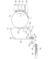
以下に、本発明の画像形成装置の1例として、一次転写を繰り返すカラー画像形成装置を示す。図8は、本発明の画像形成装置の一例を示す概略構成図である。
図8に示す画像形成装置は、像担持体としての感光体ドラム101、中間転写体としての中間転写ベルト102、転写電極であるバイアスローラ103、被転写体である用紙を供給するトレー104、BK(ブラック)トナーによる現像装置105、Y(イエロー)トナーによる現像装置106、M(マゼンタ)トナーによる現像装置107、C(シアン)トナーによる現像装置108、ベルトクリーナー109、剥離爪113、ベルト支持ロール121、123及び124、バックアップローラ122、導電性ローラ125、電極ローラ126、クリーニングブレード131、用紙束141、ピックアップローラ142、並びにフィードローラ143を備えてなり、中間転写ベルト102として本発明のエンドレスベルトが用いられる。
中間転写ベルト102の内側に備えられた蛇行防止ガイドは、ベルト支持ロール121、123および124に設けられた溝に沿うように位置する、もしくはベルト支持ロール121、123及び124の側縁部に当接するように位置するため、ベルト走行時、中間転写ベルト102は蛇行防止ガイドに案内される。そのため、中間転写ベルト102は、ベルト走行時、蛇行する問題を起こさない。
A color image forming apparatus that repeats primary transfer will be described below as an example of the image forming apparatus of the present invention. FIG. 8 is a schematic configuration diagram showing an example of the image forming apparatus of the present invention.
An image forming apparatus shown in FIG. 8 includes a
The meandering prevention guide provided on the inner side of the
図8に示す画像形成装置において、感光体ドラム101は矢印F方向に回転し、図示しない帯電装置でその表面が一様に帯電される。帯電された感光体ドラム101にレーザー書込み装置などの画像書き込み手段により第一色(例えば、BK)の静電潜像が形成される。この静電潜像は現像装置105によってトナー現像されて可視化されたトナー像Tが形成される。トナー像Tは感光体ドラム101の回転で導電性ローラ125が配置された一次転写部に到り、導電性ローラ125からトナー像Tに逆極性の電界を作用させることにより上記トナー像Tを静電的に中間転写ベルト102に吸着されつつ中間転写ベルト102の矢印G方向の回転で一次転写される。
In the image forming apparatus shown in FIG. 8, the
以下、同様にして第2色のトナー像、第3色のトナー像、第4色のトナー像が順次形成され中間転写ベルト102において重ね合せられて、多重トナー像が形成される。
Similarly, a second color toner image, a third color toner image, and a fourth color toner image are sequentially formed and superimposed on the
中間転写ベルト102に転写された多重トナー像は、中間転写ベルト102の回転でバイアスローラ103が設置された二次転写部に到る。二次転写部は、中間転写ベルト102のトナー像が担持された表面側に設置されたバイアスローラ103と該中間転写ベルト102の裏側からバイアスローラに対向するごとく配置されたバックアップローラ122およびこのバックアップローラ122に圧接して回転する電極ローラ126から構成される。
The multiple toner image transferred to the
用紙141は、用紙トレー104に収容された用紙束からピックアップローラ142で一枚ずつ取り出され、フィードローラ143で二次転写部の中間転写ベルト102とバイアスローラ103との間に所定のタイミングで給送される。給送された用紙141には、バイアスローラ103及びバックアップローラ122による圧接搬送と中間転写ベルト102の回転により、該中間転写ベルト102に担持されたトナー像が転写される。
The
トナー像が転写された用紙141は、最終トナー像の一次転写終了まで退避位置にある剥離爪113を作動せることにより中間転写ベルト102から剥離され、図示しない定着装置に搬送され、加圧/加熱処理でトナー像を固定して永久画像とされる。なお、多重トナー像の用紙141への転写の終了した中間転写ベルト102は、二次転写部の下流に設けたベルトクリーナー109で残留トナーの除去が行われて次の転写に備える。また、バイアスローラ103は、ポリウレタン等からなるクリーニングブレード131が常時当接するごとくとりつけられており、転写で付着したトナー粒子や紙紛等の異物が除去される。
The
単色画像の転写の場合、一次転写されたトナー像Tを直ちに二次転写して定着装置に搬送するが、複数色の重ね合わせによる多色画像の転写の場合、各色のトナー像が一次転写部で正確に一致するように中間転写ベルト102と感光体ドラム101との回転を同期させて各色のトナー像がずれないようにする。上記二次転写部では、バイアスローラ103と中間転写ベルト102を介して対向配置したバックアップローラ122に圧接した電極ローラ126にトナー像の極性と同極性の出圧(転写電圧)を印加することで該トナー像を用紙141に静電反発で転写する。
以上のようにして、画像を形成することができる。
In the case of transfer of a single color image, the primary transferred toner image T is immediately secondarily transferred and conveyed to the fixing device. In the case of transfer of a multicolor image by superimposing a plurality of colors, the toner image of each color is transferred to the primary transfer unit. Therefore, the rotation of the
As described above, an image can be formed.
次に、本発明の画像形成装置の他の一例を示す。
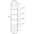
図9に示す画像形成装置は、ユニットY、M、C、BKと、用紙搬送ベルト206と、転写ロール207Y、207M、207C、207BKと、用紙搬送ロール208(図示しない)と、定着器209(図示しない)とを備えている。用紙搬送ベルト206として、本発明のエンドレスベルトが用いられる。
図9に示す画像形成装置は、ユニットY、M、C、BK、及び転写ロール207Y、207M、207C、207BKが略鉛直方向に配置されている。ユニットY、M、C、BKには、矢印の時計方向に所定の周速度(プロセススピード)をもって回転可能にそれぞれ感光体ドラム201Y、201M、201C、201BKを備えている。感光体ドラム201Y、201M、201C、201BKの周囲には、コロトロン帯電器(図示しない)と、露光器(図示しない)と、各色現像装置(図示しない)と、感光体ドラムクリーナー(図示しない)とがそれぞれ配置されている。
Next, another example of the image forming apparatus of the present invention is shown.
The image forming apparatus shown in FIG. 9 includes units Y, M, C, and BK, a
In the image forming apparatus shown in FIG. 9, units Y, M, C, and BK, and transfer rolls 207Y, 207M, 207C, and 207BK are arranged in a substantially vertical direction. The units Y, M, C, and BK are provided with
用紙搬送ベルト206は、略鉛直方向に配置されたユニットY、M、C、BK、及び転写ロール207Y、207M、207C、207BKに接するように備えられている
用紙搬送ベルト206は、用紙搬送ベルト206の内側に備えられた蛇行防止ガイドは、ベルト支持ロール210、及び211の側縁部に当接するように位置するため、ベルト走行時、用紙搬送ベルト206は蛇行防止ベルトに案内される。ベルト支持ロール210は、外径18mmの金属ロールが用いられている。用紙搬送ベルト206は、蛇行防止ガイドベルトが、支持ロール210に形成された溝を走行することで、ベルト走行時、蛇行する問題を起こさない。
本発明のエンドレスベルトを使用する場合、ベルトを支持するベルト支持ロールの少なくとも1つの外径が14〜20mmである場合でも、蛇行防止ガイドが剥離する問題なく使用することができる。
The
When the endless belt of the present invention is used, even if at least one outer diameter of the belt support roll that supports the belt is 14 to 20 mm, the meandering prevention guide can be used without any problem.
ユニットY、M、C、BKは、用紙搬送ベルト206に対して4つ並列に、ユニットY、M、C、BKの順に配置されているが、ユニットBK、Y、C、Mの順等、画像形成方法に合わせて適当な順序を設定することができる。
The four units Y, M, C, and BK are arranged in the order of the units Y, M, C, and BK in parallel with the
用紙搬送ベルト206は、ベルト支持ロール210、211によって、矢印の反時計方向に感光体ドラム201Y、201M、201C、201BKと同じ周速度をもって回転可能になっており、用紙搬送ベルト206は、ベルト用クリーニング装置214(図示しない)が備えられている。
The
転写ロール207Y、207M、207C、207BKは、用紙搬送ベルト206の内側であって、用紙搬送ベルト206と感光体ドラム201Y、201M、201C、201BKとが接している部分に対向する位置にそれぞれ配置され、感光体ドラム201Y、201M、201C、201BKと、用紙搬送ベルト206を介してトナー画像を用紙(被転写体)216に転写する転写領域(ニップ部)を形成している。
The transfer rolls 207Y, 207M, 207C, and 207BK are disposed inside the
定着装置209(図示しない)は、用紙搬送ベルト206と感光体ドラム201Y、201M、201C、201BKとのそれぞれの転写領域(ニップ部)を通過した後に搬送できるように配置されている。
用紙搬送ロール208により、用紙216は用紙搬送ベルト206に搬送される。
The fixing device 209 (not shown) is arranged so that it can be conveyed after passing through the respective transfer regions (nip portions) of the
The paper 216 is transported to the
図9に示す画像形成装置において、ユニットBKにおいては、感光体ドラム201BKを回転駆動させる。これと連動して帯電ロール202BK(図示しない)が駆動し、感光体ドラム201BKの表面を所定の極性・電位に一様に帯電させる。表面が一様に帯電された感光体ドラム201BKは、次に、露光器203BKによって像様に露光され、その表面に静電潜像が形成される。 In the image forming apparatus shown in FIG. 9, in the unit BK, the photosensitive drum 201BK is driven to rotate. In conjunction with this, a charging roll 202BK (not shown) is driven to uniformly charge the surface of the photosensitive drum 201BK to a predetermined polarity and potential. Next, the photosensitive drum 201BK whose surface is uniformly charged is exposed imagewise by the exposure device 203BK, and an electrostatic latent image is formed on the surface.
続いて該静電潜像は、ブラック現像装置204BK(図示しない)によって現像される。すると、感光体ドラム201BKの表面にトナー画像が形成される。なお、このときのトナーは一成分系のものでもよいし二成分系のものでもよい。 Subsequently, the electrostatic latent image is developed by a black developing device 204BK (not shown). As a result, a toner image is formed on the surface of the photosensitive drum 201BK. The toner at this time may be a one-component toner or a two-component toner.
このトナー画像は、感光体ドラム201BKと用紙搬送ベルト206との転写領域(ニップ部)を通過すると同時に、用紙216が静電的に用紙搬送ベルト206に吸着して転写領域(ニップ部)まで搬送され、転写ロール207BKから印加される転写バイアスにより形成される電界により、用紙216の外周面に順次、転写される。
The toner image passes through the transfer region (nip portion) between the photosensitive drum 201BK and the
この後、感光体ドラム201BK上に残存するトナーは、感光体ドラムクリーナ205BK(図示しない)によって清掃・除去される。そして、感光体ドラム201BKは、次の転写サイクルに供される。
以上の転写サイクルは、ユニットC、M及びYでも同様に行われる。
Thereafter, the toner remaining on the photosensitive drum 201BK is cleaned and removed by the photosensitive drum cleaner 205BK (not shown). Then, the photosensitive drum 201BK is subjected to the next transfer cycle.
The above transfer cycle is similarly performed in the units C, M, and Y.
転写ロール207BK、207C、207M及び207Yによってトナー画像を転写された用紙216は、さらに定着装置209(図示しない)に搬送され、定着が行われる。
以上により記録紙上に所望の画像が形成される。
The paper 216 onto which the toner image has been transferred by the transfer rolls 207BK, 207C, 207M, and 207Y is further conveyed to a fixing device 209 (not shown) for fixing.
Thus, a desired image is formed on the recording paper.
また、本発明の画像形成装置は、ベルト本体からの蛇行防止ガイドの剥離を防止できる本発明のエンドレスベルトを用いているので、エンドレスベルトの片寄り走行や蛇行を、ベルトの寿命低下を招くことなく長期にわたって簡単、確実に防止することができる。また、本発明のエンドレスベルトは、外径が14〜20mm(好ましくは16〜20mmである。)である支持ロールに支持されて用いることができるので、前記複数の支持ロールの少なくとも1つを外径が14〜20mmの支持ロールとすることができるため画像形成装置の小型化が可能となる。 In addition, the image forming apparatus of the present invention uses the endless belt of the present invention that can prevent the meandering prevention guide from peeling off from the belt body. It can be easily and reliably prevented for a long time. Further, the endless belt of the present invention can be used while being supported by a support roll having an outer diameter of 14 to 20 mm (preferably 16 to 20 mm). Since the support roll can have a diameter of 14 to 20 mm, the image forming apparatus can be downsized.
以下、本発明を実施例を用いてさらに詳細に説明するが、本発明は下記実施例によって限定されるものではない。
(実施例1)
<ベルト本体2の作製>
本発明におけるベルト本体2は、ポリアミドイミド樹脂として、溶剤可溶型のポリアミドイミド樹脂:東洋紡(株)製:バイロマックスHR16NN(固形分18質量%、溶剤:メチル−2ピロリドン)導電剤として、カーボンブラック(デギサ(株)製スペシャルブラック4:pH3.揮発分14質量%)を樹脂成分100質量部あたり、25質量部添加して、高圧衝突分散機(ジーナス(株)製)を用い、150Mpaにて、Φ0.1mmのオリフイスを通過させるとともに、2分割したスラリーを衝突させることを5回行い分散を行った。この液を外径168mmのアルミ製パイプの外面に塗布し、150℃で30分間回転乾燥後、250℃で1時間加熱して、外径168mmで、幅368mmのポリアミドイミド樹脂ベルト(ベルト本体2)を得た。このベルトの表面抵抗率は1.1×10¹²Ω/□であった。
EXAMPLES Hereinafter, although this invention is demonstrated further in detail using an Example, this invention is not limited by the following Example.
Example 1
<Preparation of
The
<蛇行防止ガイド3>
蛇行防止ガイドの材料として、厚さ1mm、JIS硬度70度の熱硬化性ウレタンシート(タイガースポリマー(株)タイプレン TR100−70)を用いて、ビグ型にて、図10(A)に示すように幅5mm、厚さ1mmで、一方の端部における凸部5の幅が2.5mm、凸部5の蛇行防止ガイド3の長手方向長さが7mmであり、他の端部の凹部以外の部分の幅が2.5mm、蛇行防止ガイド3の長手方向長さが7mmである蛇行防止ガイドを作製した。尚、蛇行防止ガイド3の長手方向長さは、後記AB間の距離が得られるように調節してある(以下の実施例及び比較例においても同様)。
<
As a material for the meandering prevention guide, a thermosetting urethane sheet (Tigers Polymer Co., Ltd. Typelen TR100-70) having a thickness of 1 mm and a JIS hardness of 70 degrees is used, as shown in FIG. The width of the
<蛇行防止ガイド付きエンドレスベルトの製作>
前記、蛇行防止ガイドに弾性接着剤としてセメダイン(株)製のアクリル変性シリコンポリマーを主成分とするスーパ−XNo8008を20μmの厚さで塗布して、ついで、前記ポリアミドイミド樹脂ベルトの片側のベルト内面に配置して、0.03Mpaの圧力で加圧して、図12(A)に示すように、図4におけるAB間の距離が2mmとなる蛇行防止ガイド付きエンドレスベルトを製作した。
また、得られた蛇行防止ガイド付きエンドレスベルトと同じ条件で製作した蛇行防止ガイドのT型剥離強度及びスラスト剥離強度を既述の方法で測定した。その結果、T型剥離強度は1.2N/mm、スラスト剥離強度は8N/mmであった。
<Production of endless belt with meandering prevention guide>
Super-XNo 8008 mainly composed of acrylic modified silicone polymer manufactured by Cemedine Co., Ltd. as an elastic adhesive is applied to the meander prevention guide in a thickness of 20 μm, and then the inner surface of the belt on one side of the polyamide-imide resin belt And an endless belt with a meandering prevention guide having a distance between AB in FIG. 4 of 2 mm was produced as shown in FIG. 12A.
Further, the T-type peel strength and the thrust peel strength of the meandering prevention guide manufactured under the same conditions as the obtained endless belt with the meandering prevention guide were measured by the method described above. As a result, the T-type peel strength was 1.2 N / mm, and the thrust peel strength was 8 N / mm.
(実施例2)
蛇行防止ガイドとして、図10(B)に示すように、凸部5の幅及び他の端部の凹部以外の部分の幅を1.0mmとした以外は、実施例1と同様にして、図12(B)に示すように、図4におけるAB間の距離が2mmとなる蛇行防止ガイド付きベルトを製作した。蛇行防止ガイドのT型剥離強度は、1N/mm、スラスト剥離強度は6N/mmであった。
(Example 2)
As a meandering prevention guide, as shown in FIG. 10 (B), the width of the
(実施例3)
蛇行防止ガイドとして、図10(C)に示すように、凸部5の幅及び他の端部の凹部以外の部分の幅を2.0mmとした以外は、実施例1と同様にして、図12(C)に示すように、図4におけるAB間の距離が2mmとなる蛇行防止ガイド付きベルトを製作した。蛇行防止ガイドのT型剥離強度は、1.1N/mm、スラスト剥離強度は7N/mmであった。
(Example 3)
As the meandering prevention guide, as shown in FIG. 10C, the width of the
(実施例4)
蛇行防止ガイドとして、図10(D)に示すように、凸部5の幅及び他の端部の凹部以外の部分の幅を2.3mm、それぞれの先端部をR=10mmの形状とし、図12(D)に示すように、図4におけるAB間の距離を2.3mmとした以外は、実施例1と同様にして、蛇行防止ガイド付きベルトを製作した。蛇行防止ガイドのT型剥離強度は、1.2N/mm、スラスト剥離強度は8N/mmであった。
Example 4
As a meandering prevention guide, as shown in FIG. 10 (D), the width of the
(実施例5)
蛇行防止ガイドとして、図11(E)に示すように、凸部5の根元部分の幅を2.3mm、凸部5の先端の面の幅を1.8mmとし、他の端部の凹部以外の部分の幅を2.3mmとした以外は、実施例1と同様にして、図13(E)に示すように、図4におけるAB間の距離が2mmとなる蛇行防止ガイド付きベルトを製作した。蛇行防止ガイドのT型剥離強度は、1.1N/mm、スラスト剥離強度は7N/mmであった。
(Example 5)
As a meandering prevention guide, as shown in FIG. 11 (E), the width of the root portion of the
(実施例6)
蛇行防止ガイドとして、図11(F)に示すように、更に蛇行防止ガイド3の凸部5を有する端部近傍のベルト本体2の側縁側をベルト本体2の中央部側に傾斜させること以外は、実施例5と同様にして、図13(F)に示すように、図4におけるAB間の距離が2mmとなる蛇行防止ガイド付きベルトを製作した。蛇行防止ガイドのT型剥離強度は、1.1N/mm、スラスト剥離強度は7N/mmであった。
(Example 6)
As the meandering prevention guide, as shown in FIG. 11 (F), the side edge side of the
(比較例1)
蛇行防止ガイドとして、図11(G)に示すように、凸部の幅を0.8mmとし、図13(G)に示すように、図4におけるAB間の距離を5mmとした以外は実施例1と同様にして、蛇行防止ガイド付きベルトを製作した。蛇行防止ガイドのT型剥離強度は、0.6N/mm、スラスト剥離強度は、4N/mmであった。
(Comparative Example 1)
As a meandering prevention guide, the embodiment is the same except that the width of the convex portion is 0.8 mm as shown in FIG. 11 (G) and the distance between AB in FIG. 4 is 5 mm as shown in FIG. 13 (G). In the same manner as in No. 1, a belt with a meandering prevention guide was produced. The meandering prevention guide had a T-type peel strength of 0.6 N / mm and a thrust peel strength of 4 N / mm.
(比較例2)
蛇行防止ガイドとして、図11(H)及び図13(H)に示すように、凸部を設けず、AB間の距離を3mmとしたこと以外実施例1と同様にして、蛇行防止ガイド付きベルトを製作した。蛇行防止ガイドのT型剥離強度は、1.2N/mm、スラスト剥離強度は、8N/mmであった。
(Comparative Example 2)
As the meandering prevention guide, as shown in FIGS. 11 (H) and 13 (H), a belt with a meandering prevention guide is provided in the same manner as in Example 1 except that no protrusion is provided and the distance between AB is 3 mm. Was made. The meandering prevention guide had a T-type peel strength of 1.2 N / mm and a thrust peel strength of 8 N / mm.
(評価)
図9に示す画像形成装置と同じ構造のベルト駆動による外径18mmの金属ロール210と外径28mmの金属ロール211の2本の金属ロールの間に、外径25mmの2本の金属ロールを設け、これら4本の金属ロールに実施例1〜6、及び比較例1〜2の蛇行防止ガイド付きベルトを50Nの張力をかけて懸架し、回転速度を15回転/分として蛇行防止ガイド付きベルトを回転させ、蛇行防止ガイド付きベルトの耐久性を試験した。なお、4本の金属ロールには、図3のように蛇行防止ガイドを規制するための溝が設けられている。試験は、蛇行防止ガイド付きベルトに破断が生じない場合には、100K回転で終了した。尚、実施例5及び6において、蛇行防止ガイドの移動方向は、図12(E)及び(F)における矢印X方向であり、ベルト本体2の中心部側は矢印Y方向であった。
(Evaluation)
Two metal rolls with an outer diameter of 25 mm are provided between two metal rolls of an outer diameter of 18 mm and a
実施例1〜6の蛇行防止ガイド付きベルトは、100K回転させても、なんら耐久性に問題がないのを確認した。これに対し、比較例1の蛇行防止ガイド付きベルトは、8K回転で、リブ端部に剥がれが観察された。比較例2では、蛇行防止ガイドの隙間があるために外径18mmのロールでベルトの屈曲が発生して、1K回転でベルトの破断が発生した。 It was confirmed that the belts with meandering prevention guides of Examples 1 to 6 had no problem in durability even when rotated 100K. On the other hand, peeling of the belt with the meandering prevention guide of Comparative Example 1 was observed at the end of the rib at 8K rotation. In Comparative Example 2, since there was a gap in the meandering prevention guide, the belt was bent with a roll having an outer diameter of 18 mm, and the belt was broken at 1K rotation.
更に、実施例4〜6については、同様の条件で更に1000K回転まで、上記評価を実施した。その結果、実施例4では、400K回転程でベルトの横方向の挙動が大きくなるのが認められ、460K回転でベルトの破断が発生した。また、実施例5及び6では、1000K回転させても、なんら耐久性に問題がないのを確認した。 Furthermore, about Examples 4-6, the said evaluation was implemented to 1000K rotation on the same conditions. As a result, in Example 4, it was recognized that the lateral behavior of the belt increased at about 400K rotation, and the belt broke at 460K rotation. Further, in Examples 5 and 6, it was confirmed that there was no problem in durability even when rotated by 1000K.
このことより、本発明は、片寄り走行や蛇行を、ベルトの寿命低下を招くことなく長期にわたって簡単、確実に防止することができる、蛇行防止ガイドを備えたエンドレスベルト、及び、前記エンドレスベルトの片寄り走行や蛇行を、ベルトの寿命低下を招くことなく長期にわたって簡単、確実に防止する蛇行防止ガイドを備えたエンドレスベルトを用い、信頼性が向上し、小型化が可能な画像形成装置を提供することができることがわかる。 Accordingly, the present invention provides an endless belt provided with a meandering prevention guide that can easily and reliably prevent shifting and meandering for a long time without deteriorating the life of the belt, and the endless belt. Providing an image-forming device with improved reliability and reduced size using an endless belt with a meander-prevention guide that can easily and reliably prevent shifting and meandering for a long time without deteriorating the life of the belt You can see that you can.
1 エンドレスベルト
2 ベルト本体
3 蛇行防止ガイド
4 感熱性接着剤シート
5 凸部
6 凹部
7 接合部
20 溝
21 支持ロール
30 (T型剥離試験用)試験片
40 (スラスト剥離試験用)試験片
42 ベルト固定部材
44 ベルト本体貫通溝
46 蛇行防止ガイド貫通溝
102 中間転写ベルト
206 用紙搬送ベルト
DESCRIPTION OF
Claims (2)
前記蛇行防止ガイドには、該蛇行防止ガイドの長手方向の一端に厚み方向から見た凸部と、該蛇行防止ガイドの長手方向の他端に該凸部に対応する凹部とが設けてあり、該凸部と凹部とが接合部を介して向き合っており、
前記凸部の先端の面の該蛇行防止ガイドの幅方向の長さが、該蛇行防止ガイドの幅の20〜50%であることを特徴とするエンドレスベルト。 An endless belt in which a belt-like meandering prevention guide is bonded to the belt body along at least one side edge in the width direction of the resin belt body formed in an endless manner,
The meander prevention guide is provided with a convex portion viewed from the thickness direction at one end in the longitudinal direction of the meander prevention guide, and a concave portion corresponding to the convex portion at the other end in the longitudinal direction of the meander prevention guide, The convex part and the concave part face each other through the joint part,
An endless belt characterized in that the length of the meandering prevention guide in the width direction of the surface of the tip of the convex portion is 20 to 50% of the width of the meandering prevention guide.
Priority Applications (1)
| Application Number | Priority Date | Filing Date | Title |
|---|---|---|---|
| JP2006126629A JP2007041530A (en) | 2005-06-27 | 2006-04-28 | Endless belt and image forming apparatus using the same |
Applications Claiming Priority (2)
| Application Number | Priority Date | Filing Date | Title |
|---|---|---|---|
| JP2005187343 | 2005-06-27 | ||
| JP2006126629A JP2007041530A (en) | 2005-06-27 | 2006-04-28 | Endless belt and image forming apparatus using the same |
Publications (2)
| Publication Number | Publication Date |
|---|---|
| JP2007041530A true JP2007041530A (en) | 2007-02-15 |
| JP2007041530A5 JP2007041530A5 (en) | 2009-06-18 |
Family
ID=37799526
Family Applications (1)
| Application Number | Title | Priority Date | Filing Date |
|---|---|---|---|
| JP2006126629A Pending JP2007041530A (en) | 2005-06-27 | 2006-04-28 | Endless belt and image forming apparatus using the same |
Country Status (1)
| Country | Link |
|---|---|
| JP (1) | JP2007041530A (en) |
Cited By (33)
| Publication number | Priority date | Publication date | Assignee | Title |
|---|---|---|---|---|
| JP2008248177A (en) * | 2007-03-30 | 2008-10-16 | Okura Ind Co Ltd | Moisture-curable urethane-based hot melt adhesive for adhering anti-meandering guide for endless belt, endless belt using the same and method for producing the endless belt |
| JP2008257118A (en) * | 2007-04-09 | 2008-10-23 | Fuji Xerox Co Ltd | Endless belt for image forming apparatus, belt stretching device for image forming apparatus, and image forming apparatus |
| JP2009025631A (en) * | 2007-07-20 | 2009-02-05 | Fuji Xerox Co Ltd | Endless belt, belt tensioning and laying device and image forming apparatus |
| JP2009103754A (en) * | 2007-10-19 | 2009-05-14 | Fuji Xerox Co Ltd | Belt tubular body and image forming apparatus provided with same |
| JP2009205160A (en) * | 2008-02-26 | 2009-09-10 | Kolon Ind Inc | Seamless tubular belt and cylinder used for manufacturing the belt, and method for manufacturing tubular belt using the cylinder |
| CN101923310A (en) * | 2009-06-10 | 2010-12-22 | 夏普株式会社 | The imaging device of transfer device and this transfer device of use |
| US7873311B2 (en) | 2007-12-05 | 2011-01-18 | Kabushiki Kaisha Toshiba | Belt transfer device for image forming apparatus |
| US10357963B2 (en) | 2012-03-05 | 2019-07-23 | Landa Corporation Ltd. | Digital printing process |
| US10357985B2 (en) | 2012-03-05 | 2019-07-23 | Landa Corporation Ltd. | Printing system |
| US10427399B2 (en) | 2015-04-14 | 2019-10-01 | Landa Corporation Ltd. | Apparatus for threading an intermediate transfer member of a printing system |
| US10434761B2 (en) | 2012-03-05 | 2019-10-08 | Landa Corporation Ltd. | Digital printing process |
| US10518526B2 (en) | 2012-03-05 | 2019-12-31 | Landa Corporation Ltd. | Apparatus and method for control or monitoring a printing system |
| US10569533B2 (en) | 2012-03-15 | 2020-02-25 | Landa Corporation Ltd. | Endless flexible belt for a printing system |
| US10569534B2 (en) | 2012-03-05 | 2020-02-25 | Landa Corporation Ltd. | Digital printing system |
| US10569532B2 (en) | 2012-03-05 | 2020-02-25 | Landa Corporation Ltd. | Digital printing system |
| US10596804B2 (en) | 2015-03-20 | 2020-03-24 | Landa Corporation Ltd. | Indirect printing system |
| US10632740B2 (en) | 2010-04-23 | 2020-04-28 | Landa Corporation Ltd. | Digital printing process |
| US10642198B2 (en) | 2012-03-05 | 2020-05-05 | Landa Corporation Ltd. | Intermediate transfer members for use with indirect printing systems and protonatable intermediate transfer members for use with indirect printing systems |
| US10759953B2 (en) | 2013-09-11 | 2020-09-01 | Landa Corporation Ltd. | Ink formulations and film constructions thereof |
| US10800936B2 (en) | 2012-03-05 | 2020-10-13 | Landa Corporation Ltd. | Ink film constructions |
| US10889128B2 (en) | 2016-05-30 | 2021-01-12 | Landa Corporation Ltd. | Intermediate transfer member |
| US10926532B2 (en) | 2017-10-19 | 2021-02-23 | Landa Corporation Ltd. | Endless flexible belt for a printing system |
| US10933661B2 (en) | 2016-05-30 | 2021-03-02 | Landa Corporation Ltd. | Digital printing process |
| US10994528B1 (en) | 2018-08-02 | 2021-05-04 | Landa Corporation Ltd. | Digital printing system with flexible intermediate transfer member |
| US11267239B2 (en) | 2017-11-19 | 2022-03-08 | Landa Corporation Ltd. | Digital printing system |
| US11321028B2 (en) | 2019-12-11 | 2022-05-03 | Landa Corporation Ltd. | Correcting registration errors in digital printing |
| US11318734B2 (en) | 2018-10-08 | 2022-05-03 | Landa Corporation Ltd. | Friction reduction means for printing systems and method |
| US11465426B2 (en) | 2018-06-26 | 2022-10-11 | Landa Corporation Ltd. | Intermediate transfer member for a digital printing system |
| US11511536B2 (en) | 2017-11-27 | 2022-11-29 | Landa Corporation Ltd. | Calibration of runout error in a digital printing system |
| US11679615B2 (en) | 2017-12-07 | 2023-06-20 | Landa Corporation Ltd. | Digital printing process and method |
| US11707943B2 (en) | 2017-12-06 | 2023-07-25 | Landa Corporation Ltd. | Method and apparatus for digital printing |
| US11787170B2 (en) | 2018-12-24 | 2023-10-17 | Landa Corporation Ltd. | Digital printing system |
| US11833813B2 (en) | 2019-11-25 | 2023-12-05 | Landa Corporation Ltd. | Drying ink in digital printing using infrared radiation |
Citations (4)
| Publication number | Priority date | Publication date | Assignee | Title |
|---|---|---|---|---|
| JP2002167021A (en) * | 2000-12-01 | 2002-06-11 | Oki Data Corp | Belt driving device and image forming device using the same |
| JP2002189342A (en) * | 2000-12-21 | 2002-07-05 | Gunze Ltd | Seamless belt with meandering preventing guide |
| JP2002341671A (en) * | 2001-05-16 | 2002-11-29 | Ricoh Co Ltd | Transfer and transport apparatus |
| JP2004184697A (en) * | 2002-12-03 | 2004-07-02 | Ricoh Co Ltd | Transfer device and image forming apparatus |
-
2006
- 2006-04-28 JP JP2006126629A patent/JP2007041530A/en active Pending
Patent Citations (4)
| Publication number | Priority date | Publication date | Assignee | Title |
|---|---|---|---|---|
| JP2002167021A (en) * | 2000-12-01 | 2002-06-11 | Oki Data Corp | Belt driving device and image forming device using the same |
| JP2002189342A (en) * | 2000-12-21 | 2002-07-05 | Gunze Ltd | Seamless belt with meandering preventing guide |
| JP2002341671A (en) * | 2001-05-16 | 2002-11-29 | Ricoh Co Ltd | Transfer and transport apparatus |
| JP2004184697A (en) * | 2002-12-03 | 2004-07-02 | Ricoh Co Ltd | Transfer device and image forming apparatus |
Cited By (36)
| Publication number | Priority date | Publication date | Assignee | Title |
|---|---|---|---|---|
| JP2008248177A (en) * | 2007-03-30 | 2008-10-16 | Okura Ind Co Ltd | Moisture-curable urethane-based hot melt adhesive for adhering anti-meandering guide for endless belt, endless belt using the same and method for producing the endless belt |
| JP2008257118A (en) * | 2007-04-09 | 2008-10-23 | Fuji Xerox Co Ltd | Endless belt for image forming apparatus, belt stretching device for image forming apparatus, and image forming apparatus |
| JP2009025631A (en) * | 2007-07-20 | 2009-02-05 | Fuji Xerox Co Ltd | Endless belt, belt tensioning and laying device and image forming apparatus |
| JP2009103754A (en) * | 2007-10-19 | 2009-05-14 | Fuji Xerox Co Ltd | Belt tubular body and image forming apparatus provided with same |
| US7873311B2 (en) | 2007-12-05 | 2011-01-18 | Kabushiki Kaisha Toshiba | Belt transfer device for image forming apparatus |
| US8045905B2 (en) | 2007-12-05 | 2011-10-25 | Kabushiki Kaisha Toshiba | Belt transfer device for image forming apparatus |
| JP2009205160A (en) * | 2008-02-26 | 2009-09-10 | Kolon Ind Inc | Seamless tubular belt and cylinder used for manufacturing the belt, and method for manufacturing tubular belt using the cylinder |
| CN101923310A (en) * | 2009-06-10 | 2010-12-22 | 夏普株式会社 | The imaging device of transfer device and this transfer device of use |
| JP2010286570A (en) * | 2009-06-10 | 2010-12-24 | Sharp Corp | Transfer device and image forming apparatus employing the same |
| US8095054B2 (en) | 2009-06-10 | 2012-01-10 | Sharp Kabushiki Kaisha | Transfer device and image forming apparatus using the same |
| US10632740B2 (en) | 2010-04-23 | 2020-04-28 | Landa Corporation Ltd. | Digital printing process |
| US10357963B2 (en) | 2012-03-05 | 2019-07-23 | Landa Corporation Ltd. | Digital printing process |
| US10800936B2 (en) | 2012-03-05 | 2020-10-13 | Landa Corporation Ltd. | Ink film constructions |
| US10434761B2 (en) | 2012-03-05 | 2019-10-08 | Landa Corporation Ltd. | Digital printing process |
| US10518526B2 (en) | 2012-03-05 | 2019-12-31 | Landa Corporation Ltd. | Apparatus and method for control or monitoring a printing system |
| US10569534B2 (en) | 2012-03-05 | 2020-02-25 | Landa Corporation Ltd. | Digital printing system |
| US10569532B2 (en) | 2012-03-05 | 2020-02-25 | Landa Corporation Ltd. | Digital printing system |
| US10357985B2 (en) | 2012-03-05 | 2019-07-23 | Landa Corporation Ltd. | Printing system |
| US10642198B2 (en) | 2012-03-05 | 2020-05-05 | Landa Corporation Ltd. | Intermediate transfer members for use with indirect printing systems and protonatable intermediate transfer members for use with indirect printing systems |
| US10569533B2 (en) | 2012-03-15 | 2020-02-25 | Landa Corporation Ltd. | Endless flexible belt for a printing system |
| US10759953B2 (en) | 2013-09-11 | 2020-09-01 | Landa Corporation Ltd. | Ink formulations and film constructions thereof |
| US10596804B2 (en) | 2015-03-20 | 2020-03-24 | Landa Corporation Ltd. | Indirect printing system |
| US10427399B2 (en) | 2015-04-14 | 2019-10-01 | Landa Corporation Ltd. | Apparatus for threading an intermediate transfer member of a printing system |
| US10889128B2 (en) | 2016-05-30 | 2021-01-12 | Landa Corporation Ltd. | Intermediate transfer member |
| US10933661B2 (en) | 2016-05-30 | 2021-03-02 | Landa Corporation Ltd. | Digital printing process |
| US10926532B2 (en) | 2017-10-19 | 2021-02-23 | Landa Corporation Ltd. | Endless flexible belt for a printing system |
| US11267239B2 (en) | 2017-11-19 | 2022-03-08 | Landa Corporation Ltd. | Digital printing system |
| US11511536B2 (en) | 2017-11-27 | 2022-11-29 | Landa Corporation Ltd. | Calibration of runout error in a digital printing system |
| US11707943B2 (en) | 2017-12-06 | 2023-07-25 | Landa Corporation Ltd. | Method and apparatus for digital printing |
| US11679615B2 (en) | 2017-12-07 | 2023-06-20 | Landa Corporation Ltd. | Digital printing process and method |
| US11465426B2 (en) | 2018-06-26 | 2022-10-11 | Landa Corporation Ltd. | Intermediate transfer member for a digital printing system |
| US10994528B1 (en) | 2018-08-02 | 2021-05-04 | Landa Corporation Ltd. | Digital printing system with flexible intermediate transfer member |
| US11318734B2 (en) | 2018-10-08 | 2022-05-03 | Landa Corporation Ltd. | Friction reduction means for printing systems and method |
| US11787170B2 (en) | 2018-12-24 | 2023-10-17 | Landa Corporation Ltd. | Digital printing system |
| US11833813B2 (en) | 2019-11-25 | 2023-12-05 | Landa Corporation Ltd. | Drying ink in digital printing using infrared radiation |
| US11321028B2 (en) | 2019-12-11 | 2022-05-03 | Landa Corporation Ltd. | Correcting registration errors in digital printing |
Similar Documents
| Publication | Publication Date | Title |
|---|---|---|
| JP2007041530A (en) | Endless belt and image forming apparatus using the same | |
| JP4643324B2 (en) | Image forming apparatus | |
| JP2008257118A (en) | Endless belt for image forming apparatus, belt stretching device for image forming apparatus, and image forming apparatus | |
| JP4863719B2 (en) | Transfer device, image forming device | |
| US20070172269A1 (en) | Image forming apparatus | |
| US10073385B2 (en) | Image forming apparatus having deviation suppression mechanism for intermediate transfer belt | |
| JP6552294B2 (en) | Image forming apparatus and pressing member | |
| JP3649270B2 (en) | Image forming apparatus using endless belt | |
| JP2006018177A (en) | Image forming apparatus | |
| JP2008076999A (en) | Endless belt and image forming apparatus provided with the same | |
| JP5092666B2 (en) | Endless belt and image forming apparatus | |
| JP2009204768A (en) | Image forming apparatus | |
| JP2003255718A (en) | Image forming device | |
| JP6961375B2 (en) | Image forming device | |
| JP5157190B2 (en) | Endless belt and image forming apparatus | |
| JP2009015043A (en) | Transfer apparatus and image forming apparatus equipped therewith | |
| JP2009103754A (en) | Belt tubular body and image forming apparatus provided with same | |
| JP2008116486A (en) | Belt tubular body and image forming device provided with it | |
| JP5120095B2 (en) | Image forming apparatus belt, belt stretching apparatus, and image forming apparatus | |
| JP2005316257A (en) | Image forming apparatus and endless belt | |
| JP4670415B2 (en) | Endless belt and image forming apparatus using the same | |
| JPH10221967A (en) | Intermediate transfer belt and image forming device using the same | |
| JP2007225689A (en) | Endless belt and image forming apparatus using the same | |
| JP2009109693A (en) | Belt for image forming apparatus, belt stretching device, and image forming apparatus | |
| JP6103362B2 (en) | Image forming apparatus |
Legal Events
| Date | Code | Title | Description |
|---|---|---|---|
| A521 | Written amendment |
Free format text: JAPANESE INTERMEDIATE CODE: A523 Effective date: 20090424 |
|
| A621 | Written request for application examination |
Free format text: JAPANESE INTERMEDIATE CODE: A621 Effective date: 20090424 |
|
| A131 | Notification of reasons for refusal |
Free format text: JAPANESE INTERMEDIATE CODE: A131 Effective date: 20110426 |
|
| A521 | Written amendment |
Free format text: JAPANESE INTERMEDIATE CODE: A523 Effective date: 20110627 |
|
| A02 | Decision of refusal |
Free format text: JAPANESE INTERMEDIATE CODE: A02 Effective date: 20110719 |