JP2007033571A - Image forming apparatus and control method for image forming apparatus - Google Patents
Image forming apparatus and control method for image forming apparatus Download PDFInfo
- Publication number
- JP2007033571A JP2007033571A JP2005213376A JP2005213376A JP2007033571A JP 2007033571 A JP2007033571 A JP 2007033571A JP 2005213376 A JP2005213376 A JP 2005213376A JP 2005213376 A JP2005213376 A JP 2005213376A JP 2007033571 A JP2007033571 A JP 2007033571A
- Authority
- JP
- Japan
- Prior art keywords
- image
- image forming
- adjustment
- print job
- forming apparatus
- Prior art date
- Legal status (The legal status is an assumption and is not a legal conclusion. Google has not performed a legal analysis and makes no representation as to the accuracy of the status listed.)
- Pending
Links
Images


Classifications
-
- G—PHYSICS
- G03—PHOTOGRAPHY; CINEMATOGRAPHY; ANALOGOUS TECHNIQUES USING WAVES OTHER THAN OPTICAL WAVES; ELECTROGRAPHY; HOLOGRAPHY
- G03G—ELECTROGRAPHY; ELECTROPHOTOGRAPHY; MAGNETOGRAPHY
- G03G15/00—Apparatus for electrographic processes using a charge pattern
- G03G15/50—Machine control of apparatus for electrographic processes using a charge pattern, e.g. regulating differents parts of the machine, multimode copiers, microprocessor control
- G03G15/5033—Machine control of apparatus for electrographic processes using a charge pattern, e.g. regulating differents parts of the machine, multimode copiers, microprocessor control by measuring the photoconductor characteristics, e.g. temperature, or the characteristics of an image on the photoconductor
- G03G15/5041—Detecting a toner image, e.g. density, toner coverage, using a test patch
-
- G—PHYSICS
- G03—PHOTOGRAPHY; CINEMATOGRAPHY; ANALOGOUS TECHNIQUES USING WAVES OTHER THAN OPTICAL WAVES; ELECTROGRAPHY; HOLOGRAPHY
- G03G—ELECTROGRAPHY; ELECTROPHOTOGRAPHY; MAGNETOGRAPHY
- G03G2215/00—Apparatus for electrophotographic processes
- G03G2215/00025—Machine control, e.g. regulating different parts of the machine
- G03G2215/00029—Image density detection
- G03G2215/00033—Image density detection on recording member
- G03G2215/00037—Toner image detection
Abstract
Description
本発明は、電子写真方式あるいは静電記録方式にて、各色成分トナー像を記録材上に転写して画像を得る画像形成装置およびその画像形成装置の制御方法に関するものである。 The present invention relates to an image forming apparatus that obtains an image by transferring each color component toner image onto a recording material by an electrophotographic system or an electrostatic recording system, and a control method for the image forming apparatus.
従来、カラー画像形成装置として、図25のような装置が利用されている。
現像手段は、マゼンタトナー現像器3M、シアントナー現像器3C、イエロートナー現像器3Y、ブラックトナー現像器3Kから構成されている。前記回転式現像器3は図示しない回転支持装置によって回転可能に支持されており、前述したカラートナー現像器が順次感光体ドラム4に対向して各色トナーによる現像が行われる。
Conventionally, an apparatus as shown in FIG. 25 is used as a color image forming apparatus.
The developing means includes a magenta
上記現像手段の構成において、感光体ドラム4が所定の角速度をもって回転駆動され、その感光体ドラム表面を帯電器8によって一様に帯電する。次に第1色目(例えばマゼンタ)の画像データに応じてON/OFF制御された露光装置によってレーザビームを露光走査させることで感光体上に第1色目の静電潜像を形成され、第1色目のマゼンタトナー現像器3Mによって現像、可視化される。この可視化された第1のトナー像は、感光体ドラム4に所定の押圧力を持って圧接されながら回転駆動される転写ドラム5表面に吸着された記録材6に転写される。前記転写工程を他のトナー(シアン、イエロー、ブラック)についても同様に繰り返し、その都度各現像器に内包された各色トナーによるトナー像を転写ドラム5上に担持された記録材上に順次転写、積層することによりカラー画像が形成され、定着器7によって定着され、画像形成装置の機外に排出される。
In the developing unit, the
ここで、上記のようなカラー画像形成装置では、転写ドラム5が数回回転しなければフルカラー画像を得ることができず、フルカラー画像形成速度が、1回の転写ドラムの回転で得ることのできる単色画像と比較して遅くなるという問題点がある。
Here, in the color image forming apparatus as described above, a full color image cannot be obtained unless the
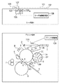
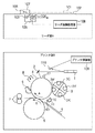
これに対し、転写ドラム上に一度に複数の画像を転写させることで、1シーケンスの転写ドラムの駆動で同時に複数のフルカラー画像を得ることができるようにすることで速度向上が図られてきた。たとえば、図26に示すように、転写ドラム5の周面に2つの記録材6A、6Bが同時に担持され、したがって転写ドラム5は1回の回転駆動について6A、6B2つの記録材に同時に2つのフルカラー画像を転写することができる。
On the other hand, speed has been improved by transferring a plurality of images on the transfer drum at a time so that a plurality of full-color images can be obtained simultaneously by driving one sequence of the transfer drum. For example, as shown in FIG. 26, two
また近年はオフィスユースなどへの対応から、モノクロ出力の高速化が要求されている。そこでこうした市場からの要求を満たすべく、次に示すような構成の画像形成装置も考案されている。 In recent years, there has been a demand for faster monochrome output for office use. Therefore, in order to satisfy such demands from the market, an image forming apparatus having the following configuration has been devised.
こうした中で、画像形成装置本体の電源を投入してから、実際に出力が可能(スタンバイ)となるまでの立ち上がり時間(ウォームアップタイム)がユーザの使い勝手にとって大きな課題となってきている。この、電源投入後の立ち上がり時間の中で大きな割合を占めるものが定着器の温度調整と画像調整である。 Under such circumstances, a rise time (warm-up time) from when the image forming apparatus main body is turned on to when output is actually possible (standby) has become a major issue for the user's convenience. A large proportion of the rise time after the power is turned on is the fixing device temperature adjustment and image adjustment.
従来から、電子写真方式を利用した画像形成装置は、記録紙上に転写されたトナーを最終的に熱定着することによって記録紙上に定着させる方法がよく用いられている。そのため定着器の温度制御は重要な要素であり、トナーをしっかりと融解させ混色させることにより発色、定着を行なうことから、高温での安定した温度調整制御が要求される。特に放置などにより定着器の温度が低い状態で電源投入された場合の立ち上げでは、いかにして短時間に定着ローラの温度を上昇させ、さらに定着ローラ全域をムラなく温調するという課題がある。これに関しては従来から定着ローラの材質として熱伝導度の高いものを利用したり、定着ローラの表層を薄層にするといった技術が提案されている。また別のアプローチとして低温でもムラなく融けやすいトナーなどの提案がされている。 2. Description of the Related Art Conventionally, an image forming apparatus using an electrophotographic method often uses a method in which toner transferred onto a recording paper is finally fixed on the recording paper by heat fixing. Therefore, temperature control of the fixing device is an important factor, and stable temperature adjustment control at a high temperature is required because color development and fixing are performed by firmly melting and mixing the toner. In particular, when the power is turned on with the fixing device at a low temperature, such as by leaving it alone, there is a problem of how to raise the temperature of the fixing roller in a short time and further control the temperature of the entire fixing roller without unevenness. . In this regard, there have been conventionally proposed techniques such as using a material having high thermal conductivity as the material of the fixing roller, or making the surface layer of the fixing roller thin. As another approach, proposals have been made for toners that melt easily even at low temperatures.
更に近年、特にフルカラー出力の増大とともに、出力画像の濃度安定性、階調安定性が求められてきている。こうしたことから、電子写真方式を利用した複写機やプリンタなどの画像形成装置の画像制御法として次のような手法が知られている。 Further, in recent years, density stability and gradation stability of output images have been demanded particularly with an increase in full-color output. For these reasons, the following methods are known as image control methods for image forming apparatuses such as copiers and printers using electrophotography.
まず、特許文献1は、画像形成装置を起動して、そのウォームアップ動作の終了後に、特定パターンを形成し、そのパターンの濃度を読み取り、その読み取った濃度値に基づいて、γ補正回路などの画像形成条件を決定する回路の動作を変更することにより、形成される画像の品質を安定させている。
First,
更に、特許文献2は、環境条件の変動により、その階調特性が変化した場合にも、再度特定パターンを形成して読み取り、再びγ補正回路などの画像形成条件を決定する回路にフィードバックすることにより、その環境条件の変動量に応じて画像品質を安定させる技術を開示している。
Furthermore,
また、特許文献3は、画像形成装置が、長期に渡って使用された場合、像担持体上のパターンを読み取った濃度と、実際にプリントアウトされた画像の濃度が一致しなくなるケースが生じてくる。そのため、記録材上に特定パターンを形成し、その濃度値によって画像形成条件を補正する方法も知られている。さらに、画像形成動作中に非画像領域に特定パターンを形成し、そのパターンの濃度を読み取り、その読み取った濃度値に基づいて、画像形成動作毎にγ補正回路などの画像形成条件を決定する回路の動作を変更することにより、刻々と変化する画像特性に対して精度よく補正を行なう方法も知られている。
しかしながら、近年、カラー画像形成装置においては、電源投入後のスタンバイまでの時間の短縮が大きな課題となっている。特に電源投入後すぐにモノクロ画像の出力や階調性にこだわらないビジネス文書などの出力を行ないたいユーザにとっては、スタンバイまでの時間を待たなければならないため、できるだけ迅速な立ち上がりが要求されている。 However, in recent years, in color image forming apparatuses, it has become a major issue to shorten the time until standby after power-on. In particular, a user who wants to output a monochrome image or a business document that does not care about gradation immediately after the power is turned on has to wait for a time until standby, so that it is required to start up as quickly as possible.
前述したように、カラー画像形成装置においては電源投入後に定着器の温調動作が行われ、ウォームアップ動作の終了後に画像調整動作が行われる。立ち上げ時間短縮のために双方の動作を同時に実行した場合、大きな電力量を必要とするため、近年の省エネルギーなどの動きと逆行することとなってしまう。
また、電源投入後の画像調整を省略した場合、立ち上げ後の最初のプリントジョブに対しては画像調整が行われない画像が出力されることになり、特に立ち上げ後最初にカラーのプリントジョブが行われた場合は濃度や階調の保証ができないという問題点がある。
As described above, in the color image forming apparatus, the temperature adjustment operation of the fixing device is performed after the power is turned on, and the image adjustment operation is performed after the warm-up operation is completed. If both operations are executed at the same time in order to shorten the start-up time, a large amount of electric power is required, which is contrary to the recent movements such as energy saving.
If image adjustment after power-on is omitted, an image without image adjustment will be output for the first print job after startup, and in particular, the first color print job after startup. However, there is a problem that the density and gradation cannot be guaranteed.
本発明は、上述の従来技術における問題点を鑑みてなされたものであり、電源投入時のウォームアップ動作終了後の画像調整を省略し、予約されたジョブの有無、および予約されたジョブがモノクロプリントであるかカラープリントであるかに応じてその後の画像調整モードを選択することによって、立ち上げ時間の短縮し、且つ、調整された画像を出力することを可能にする画像形成技術を提供することを目的とするものである。 The present invention has been made in view of the above-described problems in the prior art, omits image adjustment after the warm-up operation at the time of power-on, and determines whether there is a reserved job and whether the reserved job is monochrome. Provided is an image forming technique that can shorten a start-up time and output an adjusted image by selecting a subsequent image adjustment mode depending on whether the image is a print or a color print. It is for the purpose.
上記目的を達成するべく、本発明にかかる画像形成装置及び画像形成装置の制御方法は、主として以下の構成を備えることを特徴とする。 In order to achieve the above object, an image forming apparatus and an image forming apparatus control method according to the present invention mainly have the following configurations.
すなわち、像担持体上に現像されたトナー像を中間転写体上に転写して、記録材上に複数色のトナー像を形成する画像形成手段を有する画像形成装置は、
電源投入時に、予約された印刷ジョブがあるか判定する判定手段と、
前記判定手段の判定結果に従って、画像調整の実行を制御する調整制御手段とを備えることを特徴とする。又、前記調整制御手段は、前記予約された印刷ジョブがモノクロ出力の印刷ジョブと判定した場合、前記画像調整を行なわずに、当該印刷ジョブの画像を前記画像形成手段に形成させることを特徴とする。更に、前記調整制御手段は、前記予約された印刷ジョブがカラー出力の印刷ジョブと判定した場合、前記中間転写体の第1の領域で行なった画像調整に基づいて、前記画像形成手段は、前記中間転写体上の第2の領域に画像形成を行なうことを特徴とする。
That is, an image forming apparatus having an image forming unit that transfers a toner image developed on an image carrier onto an intermediate transfer member to form a toner image of a plurality of colors on a recording material.
A determination means for determining whether there is a reserved print job at power-on;
Adjustment control means for controlling execution of image adjustment according to the determination result of the determination means. The adjustment control unit may cause the image forming unit to form an image of the print job without performing the image adjustment when the reserved print job is determined as a monochrome output print job. To do. Further, when the adjustment control unit determines that the reserved print job is a color output print job, the image forming unit is configured to perform image adjustment based on the image adjustment performed in the first area of the intermediate transfer member. Image formation is performed on the second region on the intermediate transfer member.
あるいは、像担持体上に現像されたトナー像を中間転写体上に転写して、記録材上に複数色のトナー像を形成する画像形成手段を有する画像形成装置の制御方法は、
電源投入時に、予約された印刷ジョブがあるか判定する判定工程と、
前記判定手段の判定結果に従って、画像調整の実行を制御する調整制御工程と
を備えることを特徴とする。
Alternatively, a method of controlling an image forming apparatus having an image forming unit that transfers a toner image developed on an image carrier onto an intermediate transfer member to form a toner image of a plurality of colors on a recording material.
A determination step of determining whether there is a reserved print job at power-on;
And an adjustment control step for controlling execution of image adjustment according to the determination result of the determination means.
本発明によれば、電源投入時のウォームアップ動作終了後の画像調整を省略し、予約されたジョブの有無、および予約されたジョブがモノクロプリントであるかカラープリントであるかに応じてその後の画像調整モードを選択する。即ち、ジョブが、モノクロプリントの時は画像調整を省き、カラープリントの時は第1の領域で画像調整を行ない第2の領域で画像形成することによって、立ち上げ時間の短縮し、且つ、調整された画像を出力することを可能にする画像形成技術を提供することが可能になる。 According to the present invention, the image adjustment after the warm-up operation at the time of turning on the power is omitted, and the subsequent job depends on the presence or absence of the reserved job and whether the reserved job is a monochrome print or a color print. Select the image adjustment mode. That is, when the job is monochrome printing, image adjustment is omitted, and when color printing is performed, the image adjustment is performed in the first area and the image is formed in the second area, thereby shortening the start-up time and adjusting. It is possible to provide an image forming technique that makes it possible to output a processed image.
[第1実施形態]
図1は本発明の第1実施形態にかかる画像形成装置の構成を示す断面図である。
[First embodiment]
FIG. 1 is a cross-sectional view showing the configuration of the image forming apparatus according to the first embodiment of the present invention.
現像手段は回転式現像器3であり、マゼンタトナー現像器3M、イエロートナー現像器、3Yシアントナー現像器3Cが収納され、さらに固定式のブラックトナー現像器3Kとから構成されている。回転式現像器3は回転支持装置によって回転可能に支持されており、フルカラー出力時には前述したカラートナー現像器3M、3Y、3C、3Kが順次、像担持体としての感光体ドラム4に対向して各色トナーによる現像が行われる。また、モノクロ出力時にはカラー現像器から成る回転式現像器3は機能せずに、固定現像器3Kで現像が行われるため、モノクロ出力時にはフルカラー画像形成装置でありながら、モノクロ専用の画像形成装置と同様のスループットが得られる。
The developing means is a rotary developing
更にはこうした固定式のブラックトナー現像器を採用することにより、オフィスユースなどで一般的に消費量の多いブラックトナーの容量を大きくできるという利点を有する。 Further, by adopting such a fixed black toner developing device, there is an advantage that the capacity of black toner generally consumed in office use can be increased.
原稿台ガラス102上に、置かれた原稿101は光源103によって照射され光学系104を介してCCDセンサ105に結像される。CCDセンサ105は3列に配列されたレッド、グリーン、ブルーのCCDラインセンサー群により、ラインセンサー毎にレッド、グリーン、ブルーの色成分信号を生成する。これらの読み取り光学系ユニットは矢印の方向に走査することにより、原稿をライン毎の電気信号データ列に変換する。
A
また原稿台ガラス102上には、原稿の位置をつき当てて、原稿の斜め置かれを防ぐつき当て部材107と、その原稿台ガラス面にCCDセンサ105の白レベルを決定するためと、CCDセンサ105のスラスト方向のシェーディングを行なうための、基準白色板106が配置してある。
Further, on the
CCDセンサ105により、得られた画像信号は、リーダ画像処理部108にて画像処理された後、プリンタ部Bに送られ、プリンタ制御部109で画像処理される。
The image signal obtained by the
次に画像処理部108について説明する。図2は、本実施形態に係るリーダ部Aのリーダ画像処理部108における画像信号の流れを示すブロック図である。CCDセンサ105より出力される画像信号は(図1を参照)、アナログ信号処理部201に入力され、そこでゲイン調整、オフセット調整をされた後、A/Dコンバータ202で、各色信号毎に8bitのデジタル画像信号R1、G1、B1に変換される。その後、シェーディング補正部203に入力され、色ごとに基準白色板106の読み取り信号を用いた公知のシェーディング補正が施される。
Next, the
クロック発生部211は、1画素単位のクロックを発生する。また、主走査アドレスカウンタ212では、クロック発生部211からのクロックを計数し、1ラインの画素アドレス出力を生成する。そして、デコーダ213は、主走査アドレスカウンタ212からの主走査アドレスをデコードして、シフトパルスやリセットパルス等のライン単位のCCD駆動信号や、CCDからの1ライン読み取り信号中の有効領域を表すVE信号、ライン同期信号HSYNCを生成する。なお、主走査アドレスカウンタ212はHSYNC信号でクリアされ、次のラインの主走査アドレスの計数を開始する。
The clock generator 211 generates a clock for each pixel. The main
CCDセンサ105の各ラインセンサーは、相互に所定の距離を隔てて配置されているため、図2のラインディレイ回路204において、副走査方向の空間的ずれを補正する。具体的には、B信号に対して副走査方向で、R、Gの各信号を副走査方向にライン遅延させてB信号に合わせる。
Since the line sensors of the
入力マスキング部205は、CCDセンサのR、G、Bのフィルタの分光特性で決まる読み取り色空間を、NTSCの標準色空間に変換する部分であり、次式のようなマトリックス演算を行なう。
The

光量/濃度変換部(LOG変換部)206はルックアップテーブルROMにより構成され、R4、G4、B4の輝度信号がM0、C0、Y0の濃度信号に変換される。ライン遅延メモリ207は、不図示の黒文字判定部で、R4、G4、B4信号から生成されるUCR、FILTER、SEN等の判定信号までのライン遅延分だけ、M0、C0、Y0の画像信号を遅延させる。
The light quantity / density conversion unit (LOG conversion unit) 206 is configured by a look-up table ROM, and the luminance signals of R4, G4, and B4 are converted into density signals of M0, C0, and Y0. The
マスキング及びUCR回路208は、入力されたM1、C1、Y1の3原色信号により黒信号(K)を抽出し、更に、プリンタ部Bでの記録色材の色濁りを補正する演算を施して、M2、C2、Y2、K2の信号を各読み取り動作の度に順次、所定のビット幅(8bit)で出力する。
The masking and
γ補正回路209は、リーダ部Aにおいて、プリンタ部Bの理想的な階調特性に合わせるべく濃度補正を行なう。また、空間フィルタ処理部(出力フィルタ)210は、エッジ強調又はスムージング処理を行なう。 The γ correction circuit 209 performs density correction in the reader unit A so as to match the ideal gradation characteristics of the printer unit B. The spatial filter processing unit (output filter) 210 performs edge enhancement or smoothing processing.
このように処理されたM4、C4、Y4、Bk4の面順次の画像信号は、プリンタ制御部109に送られ、プリンタ部BでPWMによる濃度記録が行われる。
The M4, C4, Y4, and Bk4 frame sequential image signals processed in this way are sent to the
また、CPU214はリーダ部内の制御を行ない、RAM215、ROM216が接続される。ある。操作部217は表示器218を有する。
The
図3は、図2に示す画像処理部108における各制御信号のタイミングを示す図である。同図において、VSYNC信号は、副走査方向の画像有効区間信号であり、論理"1"の区間において、画像読み取り(スキャン)を行って、順次、(M)、(C)、(Y)、(K)の出力信号を形成する。また、VE信号は、主走査方向の画像有効区間信号であり、論理"1"の区間において主走査開始位置のタイミングをとり、主にライン遅延のライン計数制御に用いられる。そして、CLOCK信号は画素同期信号であり、"0"→"1"の立ち上がりタイミングで画像データを転送するのに用いられる。
FIG. 3 is a diagram showing the timing of each control signal in the
次にプリンタ部Bの説明を行なう。図1において、帯電手段8はコロナ帯電器であり、バイアスを印加することで、感光体ドラム4の表面を一様に負極性に帯電させる。画像データは、プリンタ制御部109に含まれるレーザドライバ及びレーザ光源110を介してレーザ光に変換される。そのレーザ光はポリゴンミラー1及びミラー2により反射され、一様に帯電された感光体ドラム4上に照射される。レーザ光の走査により潜像が形成された感光ドラム4は、図中に示す矢印Aの方向に回転する。
Next, the printer unit B will be described. In FIG. 1, charging means 8 is a corona charger, and the surface of the
図27は現像手段3の詳細図を示す。現像手段3は、マゼンタトナー現像器3M、イエロートナー現像器3Y、シアントナー現像器3Cの切り替え式の回転現像手段3aと、黒用のブラックトナー現像器3Kを有する固定現像手段3bから構成されている。尚、本実施形態においては、ブラックは磁性一成分トナー、他の3色は磁性キャリアと非磁性トナーとを含む二成分現像剤を採用している。
FIG. 27 shows a detailed view of the developing
回転現像手段3aは、回転支持装置3a1によって図3の矢印B方向へ回転可能に支持され、カラートナー現像器3M、3Y、3Cが順次感光体ドラム4に対向して各色トナーによる現像が行われる。回転現像手段3aは装置本体に対して着脱可能なプロセスカートリッジとして構成されており、各カラートナー現像器3M、3Y、3C内のトナーがなくなったときに回転現像手段3aを交換することによって再び画像形成が可能になる。
The
一方、固定現像手段3bは消費量の多いブラックトナーを収納した現像器を有するものであり、回転現像手段3aと同様にプロセスカートリッジとして構成され、装置本体に着脱可能に構成されている。この固定現像手段3bは装置本体に装着された状態では、図3に示すように、回転可能なトナー担持体である現像スリーブ3Kが感光体ドラム4と微少間隙(本実施形態では50μm 〜 500μm )をもって保持され、現像スリーブ3Kに担持されているトナーを感光体ドラム4に向けて供給するための現像領域が形成されている。
On the other hand, the fixed developing
更に、トナー容器内にはトナーをブラックトナー現像器3Kの現像スリーブ側へ送り出す送り手段3b3が設けられており、この送り手段3b3 によって送り出されたトナーを現像スリーブに供給するための供給ローラ3b4 が収容されている。この供給ローラ3b4 は現像スリーブへの安定供給、均一なトナー塗布を達成するために、ポリウレタン、シリコーン等のゴム発泡材質が好ましく用いられる。更には供給ローラ3b4 を現像スリーブに当接させると共に、周速差をもたせながら図27の矢印C方向へ回転させることが好ましい。また、現像スリーブの上方には、現像スリーブに担持されているトナーの層厚を規制する規制部材としての現像ブレード3b5 が設けられている。
Further, a feeding means 3b3 for feeding the toner to the developing sleeve side of the black
上記現像手段の構成において、感光体ドラム4の表面がコロナ帯電器8によって一様に帯電される(本実施形態では−500V)。
In the configuration of the developing unit, the surface of the
次に、第1色目(例えばマゼンタ)の画像データに応じてON/OFF制御された露光手段による露光走査がなされ、第1色目の静電潜像(本実施形態にあっては約−150 V)が感光体ドラム4に形成される。この第1色目の静電潜像は第1色目のマゼンタトナー(−極性)を内包したマゼンタ現像器3Mによって現像、可視像化される。そして、この可視像化された第1のトナー像は、感光体ドラム4に所定の押圧力を持って圧接され、感光体ドラム4の周速度と略等速の速度(本実施形態にあっては265mm/s )をもって矢印D方向へ回転駆動される転写ドラム5とのニップ部において、転写ドラム5上に担持された記録材6上に転写される。
Next, exposure scanning is performed by exposure means that is ON / OFF controlled in accordance with image data of the first color (for example, magenta), and the electrostatic latent image of the first color (about −150 V in this embodiment). ) Is formed on the
転写工程の際に記録材6に転写されずに感光体ドラム4上に残ったトナーは、感光体ドラム4に圧接されたクリーニング手段9であるクリーニングブレードにより掻き取られ、廃トナー容器に回収される。
The toner remaining on the
そして、上記の転写工程を他のトナー(イエロー、シアン、ブラック)についても同様に繰り返し、その都度各々の現像器に内包された色の異なるトナーによるトナー像を転写ドラム5上に担持された記録材6上に順次転写、積層することによりフルカラー画像が合成形成される。
Then, the above transfer process is repeated in the same manner for other toners (yellow, cyan, black), and each time a toner image of a different color toner contained in each developing device is carried on the
上記の各工程によってフルカラー画像の形成された記録材6は、転写ドラム5上から剥離された後に搬送手段によって定着装置まで搬送され、定着手段7によって加熱定着され排紙される。
The
上記に示した図1のような構成の画像形成装置においてモノクロ単色の画像形成を行なう場合は、ブラック現像器3Kが固定現像手段3bとしているため、カラー現像器を内包した回転現像手段3aを動作することなく、連続して高速の画像形成を行なうことが可能である。
When the monochrome image formation is performed in the image forming apparatus having the configuration shown in FIG. 1 as described above, the black developing
また本実施形態における画像形成装置では、感光体ドラム4上に形成されたトナーパッチパターンの反射光量を検出するためのトナーパッチ検出器40を配置する。検出器40は、LED光源10(約960nmに主波長をもつ)とフォトダイオード11を設けている。
In the image forming apparatus according to the present embodiment, a
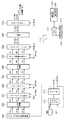
図4は本実施形態による画像形成装置の構成を示すブロック図である。 FIG. 4 is a block diagram illustrating the configuration of the image forming apparatus according to the present embodiment.
プリンタ制御部109はCPU28及び、ROM30とRAM32、テストパターン記憶部31、濃度換算回路42及びLUT25より成り立ち、リーダ部A、プリンタエンジン部100と通信できるようになっている。
The
プリンタエンジン部100において、感光体ドラム4の回りに配置されている、LED10とフォトダイオード11から成る検出器40、一次帯電器8、レーザ110、表面電位センサ12、現像器3を制御している。
In the
また、機内の空気中の水分量を測定する環境センサ33が備えられている。表面電位センサ12は現像器3より上流側に設けられる。一次帯電器8のグリッド電位、現像器3の現像バイアスは後述のようにCPU28により制御される。
Moreover, the
図5は本実施形態において、階調画像を得る画像信号処理回路を示す図である。画像の輝度信号がCCDセンサ105で得られ、リーダ画像処理部108において面順次の画像信号に変換される。この画像信号は、初期設定時のプリンタのγ特性が入力された画像信号によって表される、原画像の濃度と出力画像の濃度が一致するように、LUT25にて濃度特性が変換される。
FIG. 5 is a diagram showing an image signal processing circuit for obtaining a gradation image in the present embodiment. A luminance signal of the image is obtained by the
図6は、階調が再現される様子を4限チャートで示す図である。 FIG. 6 is a diagram showing how the gradation is reproduced with a four-limit chart.
第I象限は、原稿濃度を濃度信号に変換するリーダ部Aの読み取り特性を示す。第II象限は濃度信号をレーザ出力信号に変換するためのLUT25の変換特性を示す。第III象限はレーザ出力信号から出力濃度に変換するプリンタ部Bの記録特性を示す。第IV象限は原稿濃度から出力濃度の関係を示すこの画像形成装置のトータルの階調再現特性を示す。
The first quadrant indicates the reading characteristic of the reader unit A that converts the document density into a density signal. The second quadrant shows the conversion characteristics of the
階調数は8bitのデジタル信号で処理しているので、256階調である。
この画像形成装置では、第IV象限の階調特性をリニアにするために、第III象限のプリンタ特性がリニアでない分を第IV象限のLUT25によって補正している。LUT25は後に述べる演算結果により生成される。
Since the number of gradations is processed by an 8-bit digital signal, it is 256 gradations.
In this image forming apparatus, in order to make the gradation characteristic of the fourth quadrant linear, the printer characteristic of the third quadrant is corrected by the
LUT25にて濃度変換された後、パルス巾変調(PWM)回路26により信号がドット巾に対応した信号に変換され、レーザのON/OFFを制御するレーザドライバ27に送られる。本実施形態では、M、C、Y、Kの全色とも、パルス幅変調処理による階調再現方法を用いている。
After density conversion in the
そして、レーザ110の走査により感光体ドラム4上にはドット面積の変化により、所定の階調特性を有する潜像が形成され、現像、転写、定着という過程をへて階調画像が再生される。ここで、本実施形態で用いた画像形成装置の画像調整の手段を詳しく説明する。
Then, a latent image having a predetermined gradation characteristic is formed on the
本実施形態で用いた画像形成装置は画像調整の手段として第1の制御系と第2の制御系を有する。 The image forming apparatus used in this embodiment has a first control system and a second control system as image adjustment means.
(第1の制御系)
まず、リーダ部A、プリンタ部Bの双方を含む系の画像再現特性の安定化に関する第1の制御系について説明する。図7はリーダ部Aを用いてプリンタ部Bのキャリブレーションを行なうフロー図である。このフローは、リーダ部Aを制御するCPU214とプリンタ部Bを制御するCPU28により実現される。
(First control system)
First, a first control system related to stabilization of image reproduction characteristics of a system including both the reader unit A and the printer unit B will be described. FIG. 7 is a flowchart for calibrating the printer unit B using the reader unit A. This flow is realized by the
操作部217上に設けられた、自動階調補正というモード設定ボタンを押すことで、本制御がスタートする。図8〜図10は表示器の表示遷移図を示す。なお、本実施形態では、表示器218は図8〜図10に示す様なプシュセンサつきの液晶操作パネル(タッチパネルディスプレイ)で構成されている。
This control is started by pressing a mode setting button called automatic gradation correction provided on the
説明を図7に戻し、まず、ステップS51において、表示器218上に、テストプリント1のプリントスタートボタン81が表示され(図8(a))、それを押すことで図11に示すテストプリント1の画像がプリンタ部Bによりプリントアウトされる。
Returning to FIG. 7, first, in step S51, the
このとき、テストプリント1を形成するための用紙の有無をCPU214が判断し、用紙がない場合は図8(b)に示すような警告表示を行なう。このテストプリント1の形成時にはコントラスト電位(この詳細は後述する)は、環境に応じた標準状態のものを初期値として登録しておき、これを用いるものとする。
At this time, the
また、本実施形態に用いた画像形成装置は、複数の用紙カセットを備え、B4、A3、A4、B5等複数種の用紙サイズが選択可能となっている。 The image forming apparatus used in this embodiment includes a plurality of paper cassettes, and a plurality of types of paper sizes such as B4, A3, A4, and B5 can be selected.
しかし、この制御で使用するプリント用紙は、後の読み取り作業時に、縦置き、横置きの間違えによるエラーを避けるために、一般で言われているラージサイズ紙を用いている。すなわち、B4、A3、11×17、LGRを用いるように、設定されている。 However, the print paper used in this control is a large-size paper that is generally referred to in order to avoid errors due to a mistake in portrait orientation and landscape orientation during subsequent reading operations. That is, it is set to use B4, A3, 11 × 17, and LGR.
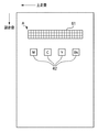
図11は、テストパターン1を示す図であり、M、C、Y、K4色分の中間階調濃度による、帯状のパターン61が形成される。
FIG. 11 is a diagram showing the
このパターン61を目視で検査することにより、スジ状の異常画像、濃度ムラ、色ムラがないことを確認する。このパターンはスラスト方向に、パッチパターン62、及び階調パターン71、72(図12)をカバーするようにCCDセンサ105の主走査方向のサイズが設定されている。
By visually inspecting this
異常が認められる場合には、再度テストプリント1のプリントを行ない、再度異常が認められた場合にはサービスマンコールとする。
If an abnormality is recognized, the
なお、この帯状のパターン61をリーダ部Aで読み取り、そのスラスト方向の濃度情報により、以後の制御を行なうかどうかの可否判断を自動で下すことも可能である。一方、パターン62はM、C、Y、Kの各色の最大濃度パッチで、濃度信号値で255レベルを用いるものとする。
It is also possible to read this belt-
ステップS52では、このテストプリント1の画像を、原稿台ガラス102上に図13のようにのせて、図9(a)に示される読み取りスタートボタン91を押すと、図9(a)に示す操作者用のガイダンス表示が表示される。
In step S52, when the image of the
図13は原稿台を上部から見た図である。左上のくさび型マークTが原稿台の原稿つき当て用のマークであり、帯状のパターン61がつき当てマークT側にくるようにして、表裏を間違えないように、操作パネル上で上述のようなメッセージを表示する(図9(a))。このようにすることで、置き間違えによるエラーを防ぐことができる。
FIG. 13 is a view of the document table as viewed from above. The wedge mark T in the upper left is a mark for touching the original on the platen, and the belt-
リーダ部Aにより、パターン62を読み取る際に、つき当てマークTから徐々に走査する。一番最初の濃度ギャップ点Aがパターン61の角で得られるので、その座標ポイントから、相対座標で、パターン62の各パッチの位置をわり出して、パターン62の濃度値を読み取る。
When the
読み取り中は図9(b)に示す表示が行われる。テストプリント1の向きや位置が不正確で読み取り不能のときは図9(c)に示すメッセージを表し、操作者が置きなおして、読み込みキー92を押すことにより再度読み取りを行なう。
得られたRGB値より、光学濃度の換算するためには、下式(2)を用いる。市販の濃度計と同じ値にするために、補正係数(k)で調整している。
During reading, the display shown in FIG. 9B is performed. When the orientation and position of the
In order to convert the optical density from the obtained RGB values, the following equation (2) is used. In order to make it the same value as a commercially available densitometer, it adjusts with the correction coefficient (k).
また、別にLUTを用いてRGBの輝度情報からMCYKの濃度情報に変換してもよい。
Alternatively, RGB luminance information may be converted into MCYK density information using an LUT.
次に得られた濃度情報から、最大濃度を補正する方法を説明する。図15は相対ドラム表面電位と上述の演算により得られた画像濃度の関係を示す図である。その時点で用いたコントラスト電位、すなわち、現像バイアス電位と、一次帯電された後レーザ光を用いて最大レベルを打った時の感光ドラムの表面電位との差が、Aという設定で得られた最大濃度DAであった場合、最大濃度の濃度域では、相対ドラム表面電位に対して画像濃度が実線Lに示すように、リニアに対応することがほとんどである。 Next, a method for correcting the maximum density from the obtained density information will be described. FIG. 15 is a diagram showing the relationship between the relative drum surface potential and the image density obtained by the above calculation. The difference between the contrast potential used at that time, that is, the development bias potential, and the surface potential of the photosensitive drum when the maximum level is applied using laser light after primary charging is the maximum obtained by setting A. In the case of the density DA, in the density range of the maximum density, the image density is almost linear as indicated by the solid line L with respect to the relative drum surface potential.
ただし、2成分現像系では、現像器内のトナー濃度が変動して、下がってしまった場合、破線Nのように、最大濃度の濃度域で、非線形特性になってしまう場合もある。 However, in the two-component development system, when the toner density in the developing device fluctuates and falls, nonlinear characteristics may occur in the density range of the maximum density as indicated by the broken line N.
従って、ここでは、最終的な最大濃度の目標値を1.6としているが、0.1のマージンを見込んで、1.7を最大濃度にあわせる制御の目標値に設定して制御量を決定する。ここでのコントラスト電位Bは、次式(3)を用いて求めることができる。 Therefore, although the final target value of the maximum density is 1.6 here, the control amount is determined by setting the target value for the control to match the maximum density with a margin of 0.1. To do. The contrast potential B here can be obtained using the following equation (3).
B=(A+Ka)×1.7/DA ...(3)
ここでKaは、補正係数であり、現像方式の種類によって、値を最適化するのが好ましい。
B = (A + Ka) × 1.7 / DA (3)
Here, Ka is a correction coefficient, and it is preferable to optimize the value depending on the type of development method.
実際には、電子写真方式では、環境によって、コントラスト電位Aの設定は、環境に応じて変えないと画像濃度が合わず、先に説明した、機内の水分量をモニタする環境センサ33の出力によって、図16に示す絶対水分量とコントラスト電位の関係のように設定を変えている。
従って、コントラスト電位を補正する方法として次式の補正係数Vcont.ratel((4)式)を、バックアップされたRAMに保存しておく。
Actually, in the electrophotographic method, depending on the environment, the setting of the contrast potential A does not match the image density unless it changes according to the environment, and is based on the output of the
Therefore, as a method for correcting the contrast potential, the following correction coefficient Vcont.ratel (formula (4)) is stored in the backed-up RAM.
Vcont.ratel=B/A ...(4)
画像形成装置が30分毎に、環境(水分量)の推移をモニタし、その検知結果に基づいてAの値を決定する度に、A×Vcont.ratelを算出して、コントラスト電位を求めることができる。
Vcont. ratel = B / A (4)
Every time the image forming apparatus monitors the transition of the environment (water content) every 30 minutes and determines the value of A based on the detection result, A × Vcont. By calculating the rate, the contrast potential can be obtained.
コントラスト電位から、グリッド電位と現像バイアス電位を求める方法を簡単に説明する。図17は、グリッド電位と感光ドラムとの関係を示す図である。
グリッド電位を−200Vにセットして、レーザ光のレベルを最低にして走査したときの表面電位VL並びにレーザ光のレベルを最高にしたときの表面電位VHを表面電位センサ12で測定する。同様にグリッド電位を−400VにしたときのVLとVHを測定する。−200Vのデータと、−400Vのデータを、補間、外挿することで、グリッド電位と表面電位との関係を求めることができる。この電位データを求めるための制御を電位測定制御と呼ぶ。
A method for obtaining the grid potential and the developing bias potential from the contrast potential will be briefly described. FIG. 17 is a diagram illustrating the relationship between the grid potential and the photosensitive drum.
The grid potential is set to -200 V, and the surface potential VL when scanning is performed with the laser light level minimized and the surface potential VH when the laser light level is maximized are measured by the surface
VLから画像上にカブリトナーが付着しないように設定されたVbg(ここでは100Vに設定)の差を設けて、現像バイアスVDCを設定する。 The development bias VDC is set by providing a difference of Vbg (here, set to 100 V) set so that fog toner does not adhere to the image from VL.
コントラスト電位Vcontは、現像バイアスVDCと、VHの差分電圧であり、このVcontが大きいほど、最大濃度が大きくとれるのは、上述した通りである。計算で求めたコントラスト電位Bにするためには、図17の関係より、何ボルトのグリッド電位が必要か、そして何ボルトの現像バイアス電位が必要かは、計算で求めることができる。 The contrast potential Vcont is a differential voltage between the development bias VDC and VH. As described above, the maximum density can be increased as the Vcont increases. In order to obtain the calculated contrast potential B, it is possible to calculate how many volts of grid potential and how many development bias potentials are required from the relationship shown in FIG.
説明を図7のフローチャートに戻し、ステップS53では、最大濃度を最終的な目標値より、0.1高くなるようにコントラスト電位を求め、このコントラスト電位が得られるように、グリッド電位および現像バイアス電位をCPU28がセットする。 Returning to the flowchart of FIG. 7, in step S53, the contrast potential is obtained so that the maximum density is 0.1 higher than the final target value, and the grid potential and the developing bias potential are obtained so that this contrast potential can be obtained. Is set by the CPU.
ステップS54にて、求めたコントラスト電位が、制御範囲にあるかどうかを判断する。制御範囲からはずれている場合には(S54−No)、現像器等に異常があるものと判断して、対応する色の現像器をチェックするように、サービスマンにわかるように、エラーフラグをたてておき、所定のサービスモードでそのエラーフラッグをサービスマンが見られるようにする(S55)。 In step S54, it is determined whether or not the obtained contrast potential is within the control range. If it is out of the control range (S54-No), it is determined that there is an abnormality in the developing device or the like, and an error flag is set so that the service person can check the corresponding color developing device. In advance, the serviceman can see the error flag in a predetermined service mode (S55).
ここでは、そのような異常時には制御範囲ぎりぎりの値にリミッターをかけて、修正制御して、制御を継続させることも可能である。 Here, when such an abnormality occurs, it is also possible to apply a limiter to the limit value just below the control range and perform correction control to continue the control.
以上の様に、ステップS53で求めたコントラスト電位になるように、CPU28によりグリッド電位と現像バイアス電位の設定を行なう。
As described above, the
図24に、濃度変換特性図を示す。本実施形態での最大濃度を最終目標値より高めに設定する最大濃度制御により第III象限のプリンタ特性図は実線Jのようになる。もし仮に、このような制御を行なわないときには、破線Hのような1.6に達しないプリンタ特性になる可能性もある。破線Hの特性の場合LUT25をいかに設定しても、LUT25は最大濃度を上げる能力は持ち合わせていないので、濃度DHと1.6の間の濃度は再現不可能となる。
FIG. 24 shows a density conversion characteristic diagram. The printer characteristic diagram in the third quadrant becomes a solid line J by the maximum density control in which the maximum density in this embodiment is set higher than the final target value. If such control is not performed, printer characteristics that do not reach 1.6 as indicated by the broken line H may be obtained. In the case of the characteristics indicated by the broken line H, no matter how the
実線Jのように最大濃度をわずかに越える設定になっていれば、確実に、第IV象限のトータル階調特性で、濃度再現域は保証される。 If the setting is slightly higher than the maximum density as indicated by the solid line J, the density reproduction range is assured with the total gradation characteristics in the fourth quadrant.
次に、図7のステップS56において、図10(a)のように操作パネル上に、テストプリント2の画像のプリントスタートボタン150が現れ、それを押すことで図12のテストプリント2の画像がプリントアウトされる。プリント中は図10(b)のような表示となる。
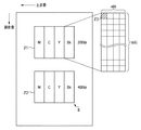
Next, in step S56 of FIG. 7, the
図12はテストプリント2のM、C、Y、Kの各色、4列16行の全部で64階調分のグラデーションのパッチ群を示す。ここで、64階調分は、全部で256階調あるうちの、濃度の低い領域を重点的にレーザ出力レベルを割り当ててあり、高濃度領域は、レーザ出力レベルをまびいている。このようにすることにより、特にハイライト部における階調特性を良好に調整することができる。
FIG. 12 shows gradation patches for 64 tones in total for each color of M, C, Y, and K of the
図12において、71は解像度200lpi(lines/inch)のパッチ、72は400lpi(lines/inch)のパッチである。各解像度の画像を形成するためには、パルス幅変調回路26において、処理の対象となっている画像データとの比較に用いられる三角波の周期を複数用意することによって実現できる。
In FIG. 12,
なお、本画像形成装置は、階調画像は200lpiの解像度で、文字等の線画像は400lpiの解像度で、作成している。この2種類の解像度で同一の階調レベルのパターンを出力しているが、解像度のちがいで、階調特性が大きく異なる場合には、解像度に応じて先の階調レベルを設定するのがより好ましい。また、テストプリント2は、LUT25を作用させずに、パターンジェネレータ29から発生させることができる。
In the image forming apparatus, the gradation image is generated with a resolution of 200 lpi, and the line image of a character or the like is generated with a resolution of 400 lpi. Patterns with the same gradation level are output at these two resolutions, but if the gradation characteristics differ greatly due to the difference in resolution, it is better to set the previous gradation level according to the resolution. preferable. Further, the
図14は、テストプリント2の出力を、原稿台ガラス102上に置いたときに、上方から見た模式図である。左上のくさび型マークTが原稿台の原稿つき当て用のマークであり、Bkのパターンが、つき当てマークT側にくるようにして、なおかつ、表裏を間違えないように操作パネル上にメッセージが表示される(図10(c))。このようにすることで、置き間違えによるエラーを防ぐことが可能になる。
FIG. 14 is a schematic view of the output of the
ステップS57では、リーダ部Aにて、パターンを読み取る際に、つき当てマークTから徐々に走査し、一番最初の濃度ギャップ点Bが得られるので、その座標ポイントから、相対座標でパターンの各色パッチの位置を割り出して、テストプリント2の出力を読み取る。
In step S57, when the pattern is read by the reader unit A, the pattern is scanned gradually from the contact mark T, and the first density gap point B is obtained. The position of the patch is determined, and the output of the
図18はパッチ(図12の73)あたりの読むポイントを示す。パッチの内部を、読み取りポイント(x)を16ポイントとり、得られた信号を平均化する。ポイント数は読み取り装置、画像形成装置によって最適化するのが好ましい。 FIG. 18 shows points to read per patch (73 in FIG. 12). Inside the patch, 16 reading points (x) are taken, and the obtained signals are averaged. The number of points is preferably optimized by a reading device and an image forming apparatus.
図19は、各パッチ毎に16ポイントの値が平均化されたRGB信号を、先に示した光学濃度への変換方法により濃度値に直し、左縦軸にその出力濃度として、横軸にレーザ出力レベルをプロットした図である。 FIG. 19 shows an RGB signal obtained by averaging 16 points for each patch, converted into an optical density value by the above-described method of converting to optical density, the output density on the left vertical axis, and the laser on the horizontal axis. It is the figure which plotted the output level.
更に、図19の右縦軸は紙のベース濃度レベルを示し、本実施形態では左縦軸に相当する0.08を0レベルに、この画像形成装置の最大濃度として設定している左縦軸に相当する1.60を255レベルに正規化している。 Further, the right vertical axis in FIG. 19 shows the base density level of the paper. In this embodiment, 0.08 corresponding to the left vertical axis is set to 0 level, and the left vertical axis is set as the maximum density of the image forming apparatus. 1.60 corresponding to is normalized to 255 levels.
得られたデータがC点のように、特異的に濃度が高かったり、D点のように、低かったりした場合には、原稿台ガラス102上に汚れがあったり、テストパターン上に不良があったりする。このため、データ列に連続性が保存されるように、傾きにリミッターをかけ、補正を行なうものとする。ここでは具体的傾きが3以上の時は、3に固定し、マイナス値の時は、その前のレベルと同じ濃度レベルに補正している。
When the obtained data has a specific high density, such as point C, or low, such as point D, there is a stain on the
LUT25の内容は前述したように、図19の濃度レベルを入力レベル(図6の濃度信号軸)に、レーザ出力レベルを出力レベル(図6のレーザ出力信号軸)に座標を入れ換えるだけで、簡単に作成できる。パッチに対応しない濃度レベルについては、補間演算により値を求める。このときに、入力レベル0レベルに対して、出力レベルは0レベルになるように、制限条件を設けている。
As described above, the contents of the
そして、説明を図7のフローチャートに戻し、ステップS58で上述の様に作成した変換内容をLUT25に設定する。
Then, the description returns to the flowchart of FIG. 7, and the conversion content created as described above is set in the
以上の処理により、読取装置を用いた第1の制御系によるコントラスト電位制御とγ変換テーブル作成が完了する。上述の処理中には、図10(d)のような表示が行われ、完了すると図10(e)のように表示される。 With the above processing, contrast potential control and γ conversion table creation by the first control system using the reading device are completed. During the above-described processing, the display as shown in FIG. 10D is performed, and when completed, the display is as shown in FIG.
(第2の制御系)
次に、通常画像形成中に行なう画像制御として、プリンタ部B単独の画像再現特性の安定化に関する第2の制御系について説明する。本制御は、感光ドラム4上のパッチパターン濃度を検出し、前述のLUT25を補正することにより、画像安定化を達成する。
(Second control system)
Next, a second control system relating to stabilization of image reproduction characteristics of the printer unit B alone will be described as image control performed during normal image formation. This control achieves image stabilization by detecting the patch pattern density on the
図20は感光ドラム4に相対するLED10と、フォトダイオード11から成るフォトセンサ40からの信号を処理する処理回路の構成を示す図である。フォトセンサ40に入射された感光ドラム4からの近赤外光は、フォトセンサ40により電気信号に変換される。電気信号はA/D変換回路41により0〜5Vの出力電圧を0〜255レベルのデジタル信号に変換される。そして、濃度換算回路42により濃度に変換される。
FIG. 20 is a diagram showing a configuration of a processing circuit that processes signals from the photosensor 40 including the
本実施形態で使用したフォトセンサ40は、感光ドラム4からの正反射光のみを検出するよう構成されているものとする。図21は、感光ドラム4上の濃度を各色の面積階調により段階的に変えていった時の、フォトセンサ40出力と出力画像濃度との関係を示す。ここでは、トナーが感光体ドラム4に付着していない状態におけるフォトセンサ40の出力を5V、すなわち、255レベルに設定している。
It is assumed that the photosensor 40 used in the present embodiment is configured to detect only regular reflection light from the
図21からわかるように、各トナーによる面積被覆率が大きくなり画像濃度が大きくなるに従い、感光ドラム4単体よりフォトセンサ40出力が小さくなる。これらの特性から、各色専用の、センサ出力信号から濃度信号に変換するテーブル42aを持つことにより、各色とも精度良く濃度信号を読み取ることができる。
As can be seen from FIG. 21, as the area coverage by each toner increases and the image density increases, the output of the
第2の制御系は第1の制御系により達成された色再現性の安定維持が目的であるため、第1の制御系による制御の終了直後の状態を目標値として設定する。図22は目標値設定の処理の流れを示す。第1の制御系による制御の終了した時点で(S2201)、M、C、Y、Kの各色毎のパッチパターンを感光ドラム上に形成して、フォトセンサ40で検知する(S2202)。ここで、パッチのレーザ出力は、各色とも濃度信号(図6の濃度信号軸)で128レベルを用いている。この際、LUT25の内容ならびに、コントラスト電位の設定は、第1の制御系で得たものを用いる(S2203)。このときの濃度値128を第2の制御系の目標値とし(S2204)、バックアップしておく。目標値は第1の制御系による制御が行われるごとに更新される。
Since the purpose of the second control system is to maintain stable color reproducibility achieved by the first control system, the state immediately after the end of the control by the first control system is set as the target value. FIG. 22 shows a flow of target value setting processing. When the control by the first control system is completed (S2201), patch patterns for M, C, Y, and K colors are formed on the photosensitive drum and detected by the photosensor 40 (S2202). Here, the laser output of the patch uses 128 levels for each color in the density signal (density signal axis in FIG. 6). At this time, the contents of the
第2の制御系は、感光ドラム4上に形成したパッチ濃度を検出し、第1の制御系で得たγLUTを随時補正していく制御である。パッチのレーザ出力は、目標値設定時と同様であることが重要であり、各色とも濃度信号(図6の濃度信号軸)で128レベルを用いる。この際、LUT25の内容ならびに、コントラスト電位の設定は、その時点での通常画像形成時と同様とする。すなわち、第1の制御系で得たものを前回までの第2の制御系により補正したものを用いるものとする。
The second control system is a control for detecting the density of the patch formed on the
濃度信号128は、1.6を255に正規化した濃度スケールでパッチ出力濃度が128になるように制御されているが、プリンタの画像特性は不安定であり、常に変化を起こす可能性をもつため、測定した結果が128になるわけではなく、ΔDだけずれている場合がある。このΔDに基づき、第2の制御系では第1の制御系で作成したLUT25(γLUT)を補正する。
The
図23は、濃度信号128において出力濃度がΔDxずれた場合の、一般的な濃度信号0〜255までにおける出力濃度の変化の関係を示す図である。これを予めもっておき、制御時には、γLUT補正テーブルの濃度信号128での値がΔDになるようγ補正テーブルを規格化し、これを打ち消すように形成したLUTを、LUT25に足すことでLUT25を補正する。LUT25を書き換えるタイミングは各色ごとに異なり、書き換え準備ができた段階で、その色のレーザ書き込みが行われていない間のTOP信号により行なう。
FIG. 23 is a diagram showing the relationship of changes in output density in
像担持体(感光体ドラム4)上に現像されたトナー像を記録材担持体(転写ドラム5)上の複数の記録材(例えば、図26の6A、6B)に転写して、当該記録材上に複数のトナー像を形成する画像形成手段を有する画像形成装置は、電源投入時に、予約された印刷ジョブがあるか判定する判定部と、判定部の判定結果に従って、画像調整の実行を制御する調整制御部とを備える。 The toner image developed on the image carrier (photosensitive drum 4) is transferred to a plurality of recording materials (for example, 6A and 6B in FIG. 26) on the recording material carrier (transfer drum 5), and the recording material An image forming apparatus having an image forming unit that forms a plurality of toner images on the top controls a determination unit that determines whether there is a reserved print job when power is turned on, and controls execution of image adjustment according to a determination result of the determination unit An adjustment control unit.
また、像担持体(感光体ドラム4)上に現像されたトナー像のトナー濃度を検出するフォトセンサ40によって検出されたトナー濃度に基づいて、画像形成条件を補正する補正部を更に有し、調整制御部は、補正部により補正された画像形成条件に従って、画像調整を実行することが可能である。 The image forming apparatus further includes a correction unit that corrects the image forming condition based on the toner density detected by the photosensor 40 that detects the toner density of the toner image developed on the image carrier (photosensitive drum 4). The adjustment control unit can execute image adjustment in accordance with the image forming conditions corrected by the correction unit.
プリンタ部Bにおけるプリンタ制御部109は、CPU28の制御の下、上述の判定部、調整制御部、補正部として機能することが可能である。
The
図28は本実施形態にかかる画像調整のタイミングを制御する処理の流れを示すフローチャートである。尚、図28に示すフローチャートにおいては、判定部、調整制御部が主体として、処理が進められるものとする。 FIG. 28 is a flowchart showing a flow of processing for controlling the timing of image adjustment according to the present embodiment. In the flowchart shown in FIG. 28, it is assumed that the process is advanced mainly by the determination unit and the adjustment control unit.
図28のステップS71において画像形成装置の電源がONされ、ステッS72で定着器の温調制御が完了し、スタンバイ状態となる。ここまでの間に第2の制御系による画像調整は行なわない。 In step S71 of FIG. 28, the power supply of the image forming apparatus is turned on, and in step S72, the temperature control of the fixing device is completed, and the standby state is set. Up to this point, image adjustment by the second control system is not performed.
次にステップS73で予約されたジョブがすでにあるかどうかの判断が行われ、予約されたジョブがすでにある場合には(S74−YES)、処理をステップS74に進める。 Next, it is determined whether or not there is a reserved job in step S73. If there is already a reserved job (S74-YES), the process proceeds to step S74.
ステップS74では、予約されたジョブがモノクロプリントであるかカラープリントであるかが判別される。ここで予約されたジョブがモノクロプリントであった場合には(S74−YES)、処理はステップS75に進められてモノクロモードが設定される。そして、ステップS76において通常のモノクロシーケンスによって作像動作が行われる。 In step S74, it is determined whether the reserved job is a monochrome print or a color print. If the reserved job is a monochrome print (S74-YES), the process proceeds to step S75 to set the monochrome mode. In step S76, an image forming operation is performed by a normal monochrome sequence.
次に、ステップS77において、予約されたジョブが終了したかどうかの判別が行われ、予約されたジョブが終了であった場合には(S77−YES)、処理はステップS78に進められ、次の印刷動作に備えるために、プリンタ制御部109の制御の下、感光ドラム4は後回転動作に入る。本実施形態では、この後回転動作を行なうと同時に前述した第2の制御系による画像調整動作が行われることを特徴とする。
Next, in step S77, it is determined whether or not the reserved job has ended. If the reserved job has ended (S77-YES), the process proceeds to step S78, and the next job is performed. In order to prepare for the printing operation, the
ここで、図29は、後回転時において実行する作像シーケンスの関係を示すタイミングチャートである。後回転動作において、感光ドラム4上にカラートナーによる静電潜像を形成し、その静電潜像を現像して各色のパッチパターン(Mパッチ、Yパッチ、Cパッチ、Bkパッチ)を作像する。このパッチパターンをフォトセンサ40によって検知する動作を各色ごとに行なうことにより、濃度補正回路、γ補正回路にフィードバックが行われ、次回のジョブ以降の作像時に反映される。
Here, FIG. 29 is a timing chart showing the relationship of the image forming sequence executed during the post-rotation. In the post-rotation operation, an electrostatic latent image is formed by color toner on the
説明を図28のフローチャートに戻し、ステップS77において、予約されたジョブが更に続く場合には(S77−NO)、ステップS74に戻り同様のルーチンが繰り返される。 Returning to the flowchart of FIG. 28, if the reserved job continues in step S77 (S77-NO), the process returns to step S74 and the same routine is repeated.
一方、ステップS74の判別で、カラープリントであった場合は(S74−NO)、処理をステップS710に進め、カラーモードを設定して、処理をステップS711に進める。ステップS711において、カラー画像の作像動作が行われるが、本実施形態ではカラーの第2の制御系による画像調整を実行しながら作像動作を行なうことを特徴とする。 On the other hand, if it is determined in step S74 that the print is a color print (S74-NO), the process proceeds to step S710, the color mode is set, and the process proceeds to step S711. In step S711, an image forming operation of a color image is performed. In this embodiment, the image forming operation is performed while performing image adjustment by the second control system for color.
図30は、画像調整を実行しながら作像動作を行なう場合における作像シーケンスの関係を示すタイミングチャートである。カラー作像シーケンスにおいて、図26のように転写ドラム5上に複数の記録材6A、6B(例えば、A4サイズが2枚)を同時に担持できる(以下、2枚貼りと称す。)ことを応用し、6Aの画像領域毎(図30において、「A」と示す)において各カラートナー毎の静電潜像を現像して、各色のパッチパターン(Mパッチ、Yパッチ、Cパッチ、Bkパッチ)をAの領域毎に作像する。これをフォトセンサ40によって検知して、検知された濃度データから濃度補正回路、γ補正回路にフィードバックすることにより、6Bの画像領域(図30において、「B」と示す)に作像する画像に対する調整を行なう。この場合、図26に示す転写ドラム5上において、記録材6Aに対応する領域には、記録材を担持しないものとし、6Bに対応する領域のみに記録材を担持してM画像、Y画像、C画像、Bk画像の作像動作を行なう。
FIG. 30 is a timing chart showing the relationship of image forming sequences when an image forming operation is performed while performing image adjustment. In the color image forming sequence, it is applied that a plurality of
上記作像シーケンスを実行することにより、予約されたジョブが2枚貼りの可能なカラープリントであった場合には(S74−NO)、作像動作を行なうと同時に第2の制御系による画像調整を実行することが可能となり、電源投入後最初に予約されたジョブであっても調整されたフルカラー画像を提供することが可能となる。 If the reserved job is a color print that can be pasted two sheets by executing the above image forming sequence (S74-NO), image adjustment is performed simultaneously with the second control system. Can be executed, and an adjusted full-color image can be provided even for a job reserved for the first time after power-on.
またステップS73において予約されたジョブがなかった場合には(S73−NO)、処理をステップS712に進め、従来の構成と同様に第2の制御系による画像調整が実行される。 If there is no reserved job in step S73 (S73-NO), the process proceeds to step S712, and image adjustment by the second control system is executed as in the conventional configuration.
以上説明したとおり、本実施形態によれば、電源投入時のウォームアップ動作終了後の画像調整を省略し、予約されたジョブの有無、および予約されたジョブがモノクロプリントであるかカラープリントであるかに応じてその後の画像調整モードを選択することによって、立ち上げ時間の短縮し、且つ調整された画像を出力することが可能となる。 As described above, according to the present embodiment, image adjustment after the warm-up operation at the time of turning on the power is omitted, whether there is a reserved job, and whether the reserved job is a monochrome print or a color print. By selecting a subsequent image adjustment mode in accordance with this, it is possible to shorten the start-up time and output an adjusted image.
[実施形態2]
本実施形態では中間転写体を用いて画像形成を行なう画像形成装置に関して、画像調整のタイミングを制御する例を示す。図31は、本発明の第2実施形態にかかる画像形成装置の構成を示す断面図である。本実施形態における画像調整は中間転写体51上に検出器40を設け、パッチトナーの濃度を検知している。マゼンタ、シアン、イエローの現像器3M、3C、3Yが納められた回転式現像器3aとブラック現像器3bとを有し、適時必要時に、各現像器が、現像位置で現像を行なう構成は第1の実施形態と同様である。
[Embodiment 2]
In this embodiment, an example in which the timing of image adjustment is controlled for an image forming apparatus that forms an image using an intermediate transfer member will be described. FIG. 31 is a cross-sectional view showing a configuration of an image forming apparatus according to the second embodiment of the present invention. For image adjustment in the present embodiment, a
各色の画像情報に応じて感光体ドラム4上に形成されたトナー像は、順次中間転写体51上に転写される。フルカラーの場合には、4色トナーが中間転写体51上に転写された後、給紙ユニットから給紙された記録材6に一括で転写し、定着器7による定着工程を経て機外に排出され、フルカラープリントとなる。
The toner images formed on the
第1の実施形態で示した構成の場合、画像調整に用いるトナーパッチを感光ドラム4上に形成するが、感光ドラム4の表面は耐久時に削れや傷といった劣化要因によって、トナーパッチの読み込みの変動要因が著しく、長期的な安定性という観点ではあまり好ましくない。
In the case of the configuration shown in the first embodiment, a toner patch used for image adjustment is formed on the
そこで本実施形態では、基本的な構成は第1実施形態と同様であるが、感光ドラム4に比べて劣化要因が少なく、いっそうの安定性が得られる中間転写体51上にフォトセンサ40を設けることを特徴としている。
Therefore, in this embodiment, the basic configuration is the same as that of the first embodiment, but the
像担持体(感光体ドラム4)上に現像されたトナー像を中間転写体51上の複数の位置(例えば、図31の51A、51B)に転写して、中間転写体上の複数の位置にトナー像を転写し、複数の記録材上にトナー像を形成する画像形成手段を有する画像形成装置は、電源投入時に、予約された印刷ジョブがあるか判定する判定部と、判定部の判定結果に従って、画像調整の実行を制御する調整制御部とを備える。 The toner image developed on the image carrier (photosensitive drum 4) is transferred to a plurality of positions on the intermediate transfer body 51 (for example, 51A and 51B in FIG. 31), and is transferred to the plurality of positions on the intermediate transfer body. An image forming apparatus having an image forming unit that transfers a toner image and forms toner images on a plurality of recording materials, a determination unit that determines whether there is a reserved print job when the power is turned on, and a determination result of the determination unit And an adjustment control unit that controls execution of image adjustment.
また、中間転写体51上に転写されたトナー像のトナー濃度を検出するフォトセンサ40によって検出されたトナー濃度に基づいて、画像形成条件を補正する補正部を更に有し、調整制御部は、補正部により補正された画像形成条件に従って、画像調整を実行することが可能である。
The image forming apparatus further includes a correction unit that corrects the image forming condition based on the toner density detected by the photosensor 40 that detects the toner density of the toner image transferred onto the
プリンタ部Bにおけるプリンタ制御部109は、CPU28の制御の下、上述の判定部、調整制御部、補正部として機能することが可能である。
The
本実施形態にかかる画像調整のタイミングの制御も、第1実施形態と同様に図28のフローチャートと同様のシーケンスにより実行されるものとする。 The image adjustment timing control according to the present embodiment is also executed by the same sequence as the flowchart of FIG. 28 as in the first embodiment.
判定部により予約された印刷ジョブがあると判定された場合(図28のS73−YES)、調整制御部は、予約された印刷ジョブがモノクロ出力の印刷ジョブか、カラー出力の印刷ジョブかを判定し(図28のS74)、判定結果に従って、画像調整の実行を制御する。 When the determination unit determines that there is a reserved print job (S73-YES in FIG. 28), the adjustment control unit determines whether the reserved print job is a monochrome output print job or a color output print job. (S74 in FIG. 28) and the execution of image adjustment is controlled according to the determination result.
調整制御部は、予約された印刷ジョブがモノクロ出力の印刷ジョブと判定した場合(図28のS74−YES、S75)、画像調整を行なわずに、印刷ジョブの画像を前記画像形成手段に形成させる(図28のS76)。 If the adjustment control unit determines that the reserved print job is a monochrome output print job (S74-YES in FIG. 28, S75), the image forming unit forms an image of the print job without performing image adjustment. (S76 in FIG. 28).
調整制御部は、予約された印刷ジョブがモノクロ出力の印刷ジョブと判定した場合(図28のS74−YES、S75)、印刷ジョブの終了後、後回転動作中に、画像調整を実行する(図28のS78、図29)。 When determining that the reserved print job is a print job for monochrome output (S74-YES and S75 in FIG. 28), the adjustment control unit performs image adjustment during the post-rotation operation after the print job is completed (FIG. 28). 28, S78, FIG. 29).
調整制御部は、予約された印刷ジョブがカラー出力の印刷ジョブと判定した場合(図28のS74−NO、S710)、中間転写体51上の第1の領域(例えば、図31に示す51A)で画像調整を実行する(S711)。 If the adjustment control unit determines that the reserved print job is a color output print job (S74-NO in FIG. 28, S710), the first area on the intermediate transfer member 51 (for example, 51A shown in FIG. 31). In step S711, image adjustment is executed.
また、調整制御部は、予約された印刷ジョブがカラー出力の印刷ジョブと判定した場合(図28のS74−NO、S710)、第1の領域(図31に示す51A)で行なった画像調整に基づいて、画像形成手段は、中間転写体上の第2の領域(例えば、図31に示す51B)に、記録材に転写するためのトナー像を形成する(図28のS711)。この場合の記録材の搬送間隔は、第2の領域に搬送され、第1の領域に搬送されないように行なう。 In addition, when the adjustment control unit determines that the reserved print job is a color output print job (S74-NO in FIG. 28, S710), the adjustment control unit performs image adjustment performed in the first region (51A illustrated in FIG. 31). Based on this, the image forming unit forms a toner image to be transferred onto the recording material in a second region (for example, 51B shown in FIG. 31) on the intermediate transfer member (S711 in FIG. 28). In this case, the recording material is conveyed so that the recording material is conveyed to the second area and is not conveyed to the first area.
本実施形態においては、中間転写体51上でトナーパッチの読込みを行っているが、転写ドラム5や記録材6を搬送する転写ベルトなどに同様の構成のフォトセンサ40から成るトナーパッチを読込む構成を設ければ、本発明を適用可能である。例えば、本実施形態では、反射型のセンサを設けたが、転写ドラム5、あるいは転写ベルトなどに、透過性の高い材料を用いれば、透過型センサによる構成も当然適用可能である。又、前述ではドラムが1個の系で説明したが、ドラムが4色分あり中間転写ベルトに像を転写して記録材に転写する系、又は、ドラムが4色分あり搬送ベルト上の記録材に像を転写する系、でも適用される。この場合に適用されるのは、例えば、図28におけるS71からS79、S712である。
In this embodiment, the toner patch is read on the
以上説明したとおり、本実施形態によれば、電源投入時のウォームアップ動作終了後の画像調整を省略し、予約されたジョブの有無、および予約されたジョブがモノクロプリントであるかカラープリントであるかに応じてその後の画像調整モードを選択することによって、立ち上げ時間の短縮し、且つ調整された画像を出力することが可能となる。 As described above, according to the present embodiment, image adjustment after the warm-up operation at the time of turning on the power is omitted, whether there is a reserved job, and whether the reserved job is a monochrome print or a color print. By selecting a subsequent image adjustment mode in accordance with this, it is possible to shorten the start-up time and output an adjusted image.
Claims (10)
電源投入時に、予約された印刷ジョブがあるか判定する判定手段と、
前記判定手段の判定結果に従って、画像調整の実行を制御する調整制御手段と
を備えることを特徴とする画像形成装置。 An image forming apparatus having an image forming means for transferring a toner image developed on an image carrier onto an intermediate transfer member to form a plurality of color toner images on a recording material,
A determination means for determining whether there is a reserved print job at power-on;
An image forming apparatus comprising: an adjustment control unit that controls execution of image adjustment according to a determination result of the determination unit.
ことを特徴とする請求項1に記載の画像形成装置。 When the determination unit determines that there is a reserved print job, the adjustment control unit determines whether the reserved print job is a monochrome output print job or a color output print job, and the determination result The image forming apparatus according to claim 1, wherein execution of the image adjustment is controlled in accordance with
ことを特徴とする請求項1または2に記載の画像形成装置。 The adjustment control unit, when determining that the reserved print job is a monochrome output print job, causes the image forming unit to form an image of the print job without performing the image adjustment. Item 3. The image forming apparatus according to Item 1 or 2.
ことを特徴とする請求項1乃至3のいずれかに記載の画像形成装置。 The adjustment control unit, when determining that the reserved print job is a monochrome output print job, executes the image adjustment during a post-rotation operation after the print job is completed. 4. The image forming apparatus according to any one of items 1 to 3.
ことを特徴とする請求項1または2に記載の画像形成装置。 3. The image processing apparatus according to claim 1, wherein when the reserved print job is determined to be a color output print job, the adjustment control unit performs image adjustment in the first region on the intermediate transfer member. The image forming apparatus described.
ことを特徴とする請求項5に記載の画像形成装置。 When the adjustment control unit determines that the reserved print job is a color output print job, the image forming unit performs the adjustment on the intermediate transfer body based on the image adjustment performed in the first area. The image forming apparatus according to claim 5, wherein an image is formed in the area of 2.
当該検出手段によって検出されたトナー濃度に基づいて、画像形成条件を補正する補正手段とを更に有し、
前記調整制御手段は、前記補正手段により補正された画像形成条件に従って、前記画像調整を実行する
ことを特徴とする請求項1乃至6のいずれかに記載の画像形成装置。 Detecting means for detecting a toner density of a toner image developed on the image carrier or the intermediate transfer member;
Correction means for correcting the image forming conditions based on the toner density detected by the detection means;
The image forming apparatus according to claim 1, wherein the adjustment control unit performs the image adjustment in accordance with the image forming condition corrected by the correction unit.
電源投入時に、予約された印刷ジョブがあるか判定する判定工程と、
前記判定手段の判定結果に従って、画像調整の実行を制御する調整制御工程と
を備えることを特徴とする画像形成装置の制御方法。 A control method of an image forming apparatus having an image forming means for transferring a toner image developed on an image carrier onto an intermediate transfer member to form a toner image of a plurality of colors on a recording material,
A determination step of determining whether there is a reserved print job at power-on;
An image forming apparatus control method comprising: an adjustment control step of controlling execution of image adjustment according to a determination result of the determination unit.
Priority Applications (2)
| Application Number | Priority Date | Filing Date | Title |
|---|---|---|---|
| JP2005213376A JP2007033571A (en) | 2005-07-22 | 2005-07-22 | Image forming apparatus and control method for image forming apparatus |
| US11/459,195 US7580647B2 (en) | 2005-07-22 | 2006-07-21 | Image forming apparatus and control method for image forming apparatus |
Applications Claiming Priority (1)
| Application Number | Priority Date | Filing Date | Title |
|---|---|---|---|
| JP2005213376A JP2007033571A (en) | 2005-07-22 | 2005-07-22 | Image forming apparatus and control method for image forming apparatus |
Publications (2)
| Publication Number | Publication Date |
|---|---|
| JP2007033571A true JP2007033571A (en) | 2007-02-08 |
| JP2007033571A5 JP2007033571A5 (en) | 2009-11-26 |
Family
ID=37679157
Family Applications (1)
| Application Number | Title | Priority Date | Filing Date |
|---|---|---|---|
| JP2005213376A Pending JP2007033571A (en) | 2005-07-22 | 2005-07-22 | Image forming apparatus and control method for image forming apparatus |
Country Status (2)
| Country | Link |
|---|---|
| US (1) | US7580647B2 (en) |
| JP (1) | JP2007033571A (en) |
Cited By (4)
| Publication number | Priority date | Publication date | Assignee | Title |
|---|---|---|---|---|
| JP2009122201A (en) * | 2007-11-12 | 2009-06-04 | Fuji Xerox Co Ltd | Image forming apparatus |
| JP2009122465A (en) * | 2007-11-15 | 2009-06-04 | Fuji Xerox Co Ltd | Image forming device |
| JP2009222849A (en) * | 2008-03-14 | 2009-10-01 | Konica Minolta Business Technologies Inc | Image forming apparatus |
| JP2011232417A (en) * | 2010-04-26 | 2011-11-17 | Konica Minolta Business Technologies Inc | Image formation system and humidification device |
Families Citing this family (11)
| Publication number | Priority date | Publication date | Assignee | Title |
|---|---|---|---|---|
| JP4978925B2 (en) * | 2006-12-19 | 2012-07-18 | 京セラドキュメントソリューションズ株式会社 | Image forming apparatus |
| DE102007001687B4 (en) * | 2007-01-11 | 2015-09-03 | Océ Printing Systems GmbH & Co. KG | A method and apparatus for processing a measurement signal to detect a property of a toner mark |
| JP4823109B2 (en) * | 2007-03-14 | 2011-11-24 | キヤノン株式会社 | Image reading apparatus and control method thereof |
| JP4411339B2 (en) * | 2007-07-31 | 2010-02-10 | キヤノン株式会社 | Color image forming apparatus and control method thereof |
| JP5377341B2 (en) * | 2009-04-23 | 2013-12-25 | キヤノン株式会社 | Image forming apparatus |
| US20110026981A1 (en) * | 2009-07-28 | 2011-02-03 | Kabushiki Kaisha Toshiba | Image forming apparatus for obtaining multiple image by adjusting plural images |
| JP5484085B2 (en) * | 2010-01-18 | 2014-05-07 | キヤノン株式会社 | Image forming apparatus and image quality correction method thereof |
| WO2011094537A2 (en) * | 2010-01-29 | 2011-08-04 | Hillcrest Laboratories, Inc. | Embedding argb data in a rgb stream |
| JP5806451B2 (en) * | 2010-07-21 | 2015-11-10 | キヤノン株式会社 | Image forming apparatus |
| JP6624881B2 (en) * | 2015-10-19 | 2019-12-25 | キヤノン株式会社 | Image forming apparatus and control method thereof |
| JP2021081537A (en) * | 2019-11-18 | 2021-05-27 | ブラザー工業株式会社 | Image forming apparatus |
Citations (2)
| Publication number | Priority date | Publication date | Assignee | Title |
|---|---|---|---|---|
| JP2001188420A (en) * | 2000-01-05 | 2001-07-10 | Canon Inc | Image forming device |
| JP2002044309A (en) * | 2000-07-27 | 2002-02-08 | Ricoh Co Ltd | Image forming device |
Family Cites Families (3)
| Publication number | Priority date | Publication date | Assignee | Title |
|---|---|---|---|---|
| JP3428848B2 (en) | 1997-02-28 | 2003-07-22 | キヤノン株式会社 | Image processing apparatus and method |
| JP2001075318A (en) | 1999-09-06 | 2001-03-23 | Seiko Epson Corp | Method and device for adjusting density of image forming device |
| US6519425B2 (en) * | 2001-02-23 | 2003-02-11 | Hewlett-Packard Company | Image-producing methods and apparatus |
-
2005
- 2005-07-22 JP JP2005213376A patent/JP2007033571A/en active Pending
-
2006
- 2006-07-21 US US11/459,195 patent/US7580647B2/en not_active Expired - Fee Related
Patent Citations (2)
| Publication number | Priority date | Publication date | Assignee | Title |
|---|---|---|---|---|
| JP2001188420A (en) * | 2000-01-05 | 2001-07-10 | Canon Inc | Image forming device |
| JP2002044309A (en) * | 2000-07-27 | 2002-02-08 | Ricoh Co Ltd | Image forming device |
Cited By (6)
| Publication number | Priority date | Publication date | Assignee | Title |
|---|---|---|---|---|
| JP2009122201A (en) * | 2007-11-12 | 2009-06-04 | Fuji Xerox Co Ltd | Image forming apparatus |
| JP2009122465A (en) * | 2007-11-15 | 2009-06-04 | Fuji Xerox Co Ltd | Image forming device |
| JP2009222849A (en) * | 2008-03-14 | 2009-10-01 | Konica Minolta Business Technologies Inc | Image forming apparatus |
| JP4586870B2 (en) * | 2008-03-14 | 2010-11-24 | コニカミノルタビジネステクノロジーズ株式会社 | Image forming apparatus |
| US8437650B2 (en) | 2008-03-14 | 2013-05-07 | Konica Minolta Business Technologies, Inc. | Image forming apparatus |
| JP2011232417A (en) * | 2010-04-26 | 2011-11-17 | Konica Minolta Business Technologies Inc | Image formation system and humidification device |
Also Published As
| Publication number | Publication date |
|---|---|
| US20070019975A1 (en) | 2007-01-25 |
| US7580647B2 (en) | 2009-08-25 |
Similar Documents
| Publication | Publication Date | Title |
|---|---|---|
| JP2007033571A (en) | Image forming apparatus and control method for image forming apparatus | |
| JP3441994B2 (en) | Image processing apparatus and control method thereof | |
| JP3542582B2 (en) | Image processing apparatus and control method thereof | |
| JP5188313B2 (en) | Image forming apparatus and density gradation control method thereof | |
| JP2007183593A (en) | Image forming apparatus | |
| JP4371803B2 (en) | Image forming apparatus | |
| JPH07264411A (en) | Image forming device | |
| JP3854965B2 (en) | Image forming apparatus | |
| JP5344597B2 (en) | Image forming apparatus | |
| JP5207712B2 (en) | Image forming apparatus | |
| JP2007006204A (en) | Image forming device | |
| JP3885056B2 (en) | Image processing apparatus and control method thereof | |
| JP4890910B2 (en) | Image forming apparatus | |
| JP3618777B2 (en) | Image forming apparatus and image processing method | |
| JP2007062207A (en) | Method of generating patch image, image forming device and its controlling method | |
| US6538683B2 (en) | Image forming apparatus and a control method of an image forming apparatus | |
| JP2003195583A (en) | Image forming apparatus | |
| JP2004064358A (en) | Image processing method and its apparatus | |
| JP2007286461A (en) | Image correction method and image forming apparatus | |
| JP2006189789A (en) | Image forming apparatus and image forming method | |
| JP2006201556A (en) | Image forming apparatus | |
| JPH07131607A (en) | Image forming device | |
| JP2005265969A (en) | Image forming apparatus and its control method | |
| JP2005062244A (en) | Image forming apparatus | |
| JP2021047220A (en) | Image formation apparatus |
Legal Events
| Date | Code | Title | Description |
|---|---|---|---|
| A521 | Written amendment |
Free format text: JAPANESE INTERMEDIATE CODE: A523 Effective date: 20080722 |
|
| A621 | Written request for application examination |
Free format text: JAPANESE INTERMEDIATE CODE: A621 Effective date: 20080722 |
|
| A521 | Written amendment |
Free format text: JAPANESE INTERMEDIATE CODE: A523 Effective date: 20091014 |
|
| A131 | Notification of reasons for refusal |
Free format text: JAPANESE INTERMEDIATE CODE: A131 Effective date: 20100809 |
|
| A02 | Decision of refusal |
Free format text: JAPANESE INTERMEDIATE CODE: A02 Effective date: 20101203 |