JP2007018188A - System, method and apparatus for information presentation through extended sense of reality, and computer program - Google Patents
System, method and apparatus for information presentation through extended sense of reality, and computer program Download PDFInfo
- Publication number
- JP2007018188A JP2007018188A JP2005197999A JP2005197999A JP2007018188A JP 2007018188 A JP2007018188 A JP 2007018188A JP 2005197999 A JP2005197999 A JP 2005197999A JP 2005197999 A JP2005197999 A JP 2005197999A JP 2007018188 A JP2007018188 A JP 2007018188A
- Authority
- JP
- Japan
- Prior art keywords
- information
- rfid tag
- light emitting
- display
- light emission
- Prior art date
- Legal status (The legal status is an assumption and is not a legal conclusion. Google has not performed a legal analysis and makes no representation as to the accuracy of the status listed.)
- Pending
Links
Images


Abstract
Description
本発明は、拡張現実感を利用し、特に、プラントの計測制御設備の保守等において、作業対象とする設備と重ね合わせて設備仕様や保守手順などの情報を表示することで保守作業の効率化を支援する用途に用いて好適な、拡張現実感による情報提示システム、情報提示方法、情報提示装置およびコンピュータプログラムに関する。 The present invention utilizes augmented reality, and in particular, maintenance of plant measurement control equipment, etc., improves the efficiency of maintenance work by displaying information such as equipment specifications and maintenance procedures superimposed on the equipment to be worked on The present invention relates to an information presentation system based on augmented reality, an information presentation method, an information presentation device, and a computer program, which are suitable for use in supporting information.
CG(Computer Graphics)を現実の光景と重ね合わせて表示する拡張現実感を利用して必要な情報を提示することで作業を支援しようとするシステムが多数提案されている。拡張現実感とは、VR(Virtual Reality)技術を用いて実世界に仮想的な情報を付加し、人間と実世界とのインタラクションを可能にするものである。ここで、VRとは、人間が持つ幾つかの感覚器官に人工的に作り出した刺激を与えることで、実際には存在しない空間や物体を知覚させることをいう。 Many systems that support work by presenting necessary information using augmented reality that displays CG (Computer Graphics) superimposed on an actual scene have been proposed. Augmented reality adds virtual information to the real world using VR (Virtual Reality) technology and enables interaction between humans and the real world. Here, VR means that a space or an object that does not actually exist is perceived by applying artificially created stimuli to some sensory organs of human beings.
HMD(Head-Mounted Display)や情報提示用の画像を生成するコンピュータの小型化により、拡張現実感による作業支援は現実的になってきている。実空間に対する表示位置を特定せず、HMDを使って視野の一部に作業関連図書などを常時表示しておく方式を持つシステムは既に市販されている。このようなシステムを使用することで、作業中に手を塞ぐことも無く、また脇見をする必要も無く、必要な情報を得ることができる。
ただし、本来の拡張現実感が意図するところは、単なる情報の表示にとどまらず、情報を表示する位置によって、物と情報との関係を視覚的に提示することにある。例えば、カバーで覆われた装置の内部の配線をCGで表示し、保守対象の装置に指示記号を重ね合わせて表示する等、言語化し難い情報を正しく伝えることに最も威力を発揮する。このためには、視野の中の適切な位置に情報を表示する必要がある。
With the miniaturization of computers that generate images for HMD (Head-Mounted Display) and information presentation, work support based on augmented reality has become realistic. Systems that have a method of constantly displaying work-related books and the like in a part of the field of view using the HMD without specifying the display position with respect to the real space are already on the market. By using such a system, it is possible to obtain necessary information without blocking hands during work and without looking aside.
However, the original augmented reality is intended not only to display information but also to visually present the relationship between an object and information depending on the position where the information is displayed. For example, it is most effective in correctly transmitting information that is difficult to translate into language, such as displaying the internal wiring of the device covered with the cover in CG and displaying the instruction symbol superimposed on the device to be maintained. For this purpose, it is necessary to display information at an appropriate position in the visual field.
表示位置の決定には、まず、情報と関連付けられる物体が視野の中にあるか、視野のどこにあるか、等を検出しなければならない。そのためには、画像処理技術を用いるのが一般的である。画像処理では、物体の色や形状、または、特定の色や図柄の検出用マーカ、あるいはその両方を特徴点として画像から保守対象機器を検出し、検出した位置を基点に表示位置を決定する。
また、画像認識によらず、見る側の人間の位置や姿勢を検出することで表示位置を決定する方法もある(例えば、特許文献1参照)。
In addition, there is a method of determining the display position by detecting the position and posture of the person on the viewing side regardless of image recognition (see, for example, Patent Document 1).
しかしながら、特許文献1に開示された技術によれば、現実の物体に関連づけて情報を提示しようとする場合、情報を関連付ける物体の位置や方向も正確に把握できていることが必須である。したがって、点検等の保守作業では,情報を関連付けるプラント内の物体すべてについて,その配置と方向を把握する必要がある。CAD(Computer Aided Design)システムを使って設計されたプラントであれば、そこから配置座標を得ることもできるが、制御装置など建設後に移設・追設されることのある機器については正確な配置座標は望めない。また、可搬型の計測器など、その時々で位置の変わる物には対応できないといった不都合もある。 However, according to the technique disclosed in Patent Document 1, when information is to be presented in association with an actual object, it is essential that the position and direction of the object to be associated with the information can be accurately grasped. Therefore, in maintenance work such as inspection, it is necessary to grasp the arrangement and direction of all the objects in the plant to which information is related. If it is a plant designed using a CAD (Computer Aided Design) system, it is possible to obtain the arrangement coordinates from it, but for the equipment that may be relocated or added after the construction, such as a control device, the accurate arrangement coordinates. Can't hope. In addition, there is a disadvantage that it is not possible to deal with an object whose position changes from time to time, such as a portable measuring instrument.
また、画像処理を用いた場合も以下に示す不都合がある。すなわち、保守の現場で作業中の人間に拡張現実感を使って情報を提示しようとした場合は、視野の移動を考慮した画像処理が必要になる。例えば、色や形状の特徴で物体を検出する場合、撮影する角度によって2次元の画像として見える形状が変化することや、光源の位置や種類によって色が変化することを考慮した処理が必要である。
このような問題点を解決する方法として、検出用マーカを保守対象物表面に貼付する方法があった。しかし、検出用マーカを用いる場合、物体の検出が必要になる位置から必ずマーカが撮影できるように計画的にマーカを設置しておく必要がある。プラント内での保守作業のように、機器や配管が入り組んだ空間を人間が自由に動いて作業するような場合、適切なマーカ配置を計画するのは容易ではない。
In addition, there are the following inconveniences when image processing is used. In other words, when information is to be presented using augmented reality to a person who is working at a maintenance site, image processing that considers the movement of the field of view is necessary. For example, when an object is detected based on color or shape characteristics, it is necessary to take into consideration that the shape that appears as a two-dimensional image changes depending on the angle of shooting, and that the color changes depending on the position and type of the light source. .
As a method for solving such a problem, there has been a method of sticking a detection marker to the surface of a maintenance object. However, when using a detection marker, it is necessary to install the marker systematically so that the marker can be photographed without fail from the position where the object needs to be detected. When a human moves freely in a space where equipment and piping are involved like maintenance work in a plant, it is not easy to plan an appropriate marker arrangement.
保守作業の対象は、タービンのように作業者よりも大きな機器もあれば、メータやスイッチのように小さな機器もあり、形状も大きさもさまざまである。また、制御盤のように外見の似通った装置、あるいは部品が同じ場所に集中していることが多く、特徴点によって個々の保守対象機器を区別しにくい。
一方で、作業者の位置や姿勢は作業に伴って動くため、画像処理によって情報の表示位置を決定しようとする場合、刻々と変化する撮影画像に対する高速な画像処理が要求される。プラント内にある多種多様な保守対象機器に対して、拡張現実感を用いることによって情報を表示しようとする場合、現実空間の画像から保守対象機器の色や形状の特徴点によらず保守対象機器を高速に検出し、保守対象機器の位置と方向を特定する方法が必要である。
The objects of maintenance work include equipment that is larger than the operator, such as turbines, and small equipment, such as meters and switches, that vary in shape and size. In addition, devices or parts having similar appearances such as a control panel are often concentrated in the same place, and it is difficult to distinguish individual maintenance target devices by feature points.
On the other hand, since the position and posture of the worker move with the work, when trying to determine the display position of information by image processing, high-speed image processing is required for a captured image that changes every moment. When displaying information by using augmented reality for a variety of maintenance target devices in the plant, the maintenance target device is used regardless of the features of the color or shape of the maintenance target device from the image of the real space. It is necessary to have a method for detecting the position and direction of the maintenance target device at high speed.
本発明は前記した事情に基づいてなされたものであり、例えば、プラント内の機器や配管等、特徴点によって個々の保守対象機器を区別しにくい物体を対象に、作業者の位置や姿勢の変化によって刻々と変化する撮影画像から、保守対象機器の存在と、保守対象機器の位置と方向を画像処理の負荷を抑えて高速に特定でき、物と情報の関係を可視化する拡張現実感を実現することのできる、拡張現実感による情報提示システム、情報提示方法、情報提示装置およびコンピュータプログラムを提供することを目的とする。 The present invention has been made based on the above-described circumstances, for example, changes in the position and posture of an operator for an object that is difficult to distinguish individual maintenance target devices by feature points, such as equipment and piping in a plant. The presence of the maintenance target device and the position and direction of the maintenance target device can be identified at high speed with reduced image processing load, and the augmented reality that visualizes the relationship between objects and information can be realized. An object of the present invention is to provide an information presentation system, an information presentation method, an information presentation device, and a computer program based on augmented reality.
本発明は、例えば、プラント内の機器・配管・計測器など保守作業に関係する保守対象機器に対して発光型RFID(Radio Frequency Identification)タグを装着し、保守員が携行するリーダライタからの発信によって、情報提示の保守対象機器に関係した発光型RFIDタグを選択的に発光させ、保守対象機器の位置と方向を簡単な画像処理により検出可能とした。
このため、情報提示装置は、撮影装置からの画像を取り込み、発光している発光型RFIDタグの位置を計算し、その画像から計算した発光型RFIDタグの座標を基点とし、作業に関連した情報をCGに変換して表示装置に表示する構成とした。
The present invention, for example, attaches a light emitting type RFID (Radio Frequency Identification) tag to maintenance target equipment related to maintenance work such as equipment, piping, and measuring instruments in a plant, and transmits from a reader / writer carried by a maintenance staff. Thus, the light emitting RFID tag related to the maintenance target device for information presentation is selectively made to emit light, and the position and direction of the maintenance target device can be detected by simple image processing.
For this reason, the information presenting apparatus captures an image from the photographing apparatus, calculates the position of the light emitting RFID tag that emits light, and uses the coordinates of the light emitting RFID tag calculated from the image as the base point to provide information related to the work. Is converted to CG and displayed on the display device.
本発明によれば、例えば、プラント内の機器や配管等、特徴点によって個々の保守対象機器を区別しにくいような物体を対象に、作業者の位置や姿勢の変化によって刻々と変化する撮影画像から、前記保守対象機器の存在と、保守対象機器の位置と方向を画像処理の負荷を抑えて高速に特定でき、物と情報の関係を可視化する拡張現実感を実現することができる。 According to the present invention, for example, an object that is difficult to distinguish individual maintenance target devices by feature points such as equipment and piping in a plant, and the captured image that changes every moment according to a change in the position and posture of the worker. Therefore, the existence of the maintenance target device and the position and direction of the maintenance target device can be identified at high speed while suppressing the load of image processing, and an augmented reality that visualizes the relationship between the object and the information can be realized.
[システム]
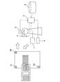
以下、本発明の実施形態について図面を参照しながら詳細に説明する。図1は、本発明の実施形態にかかわる拡張現実感による情報提示システムのシステム構成の一例を示す図である。ここでは、保守の対象となる機器(保守対象機器)2に発光型RFIDタグ1を装着し、当該機器に関連する情報を表示する場合の構成が例示されている。
保守対象機器2には、情報表示のための基点としたい位置に発光型RFIDタグ1が装着(例えば、貼付)されている。また、保守作業員には、情報提示装置としての、例えば、ウエアラブルコンピュータが装着され、当該ウエアラブルコンピュータにより保守対象機器2に関連する情報を、CGを用いて表示する。
[system]
Hereinafter, embodiments of the present invention will be described in detail with reference to the drawings. FIG. 1 is a diagram showing an example of a system configuration of an information presentation system based on augmented reality according to an embodiment of the present invention. Here, a configuration in the case where the light emitting RFID tag 1 is attached to a device (maintenance target device) 2 to be maintained and information related to the device is displayed is illustrated.
The
[ウェアラブルコンピュータ]
ウエアラブルコンピュータは、現実空間を撮影するために必要なカメラ(撮影装置)3と、情報表示用のHMD(表示装置)4と、カメラ3によって撮影された画像を処理し、また、現実空間に合わせて表示を調整したCGを生成してHMD4に出力する処理装置5と、保守作業に関連した情報が格納される記憶装置6と、発光型RFIDタグ1に対してデータの読み書きを行うリーダ/ライタ(R/W)7と、入力装置8を構成要素として持ち、保守作業員により常時携行される。
発光型RFIDタグ1は、通常のRFIDタグが持つ構成に発光部を付加し、特定のコマンドを受信したときにその発光部に対して電力を供給するスイッチを設けたものであり、その詳細は、例えば、特開2003−317050号公報に開示されている。
[Wearable computer]
The wearable computer processes a camera (photographing device) 3 necessary for photographing a real space, an HMD (display device) 4 for displaying information, and an image photographed by the
The light emitting RFID tag 1 includes a light emitting unit added to a configuration of a normal RFID tag, and a switch that supplies power to the light emitting unit when a specific command is received. For example, it is disclosed by Unexamined-Japanese-Patent No. 2003-317050.
図2は、本発明の実施形態にかかわる拡張現実感による情報提示システムの動作を説明するために引用した動作シーケンス図である。
以下、図2に示す動作シーケンス図を参照しながら図1に示す本発明の拡張現実感による情報提示システムの動作を説明する。
FIG. 2 is an operation sequence diagram quoted for explaining the operation of the information presentation system according to the augmented reality according to the embodiment of the present invention.
The operation of the information presentation system according to the augmented reality of the present invention shown in FIG. 1 will be described below with reference to the operation sequence diagram shown in FIG.
[システムの処理(シーケンス図)]
動作に先立ち、記憶装置6には、これから行う作業に関する情報、例えば、保守手順書と,保守対象機器2に貼付された発光型RFIDタグ1に固有の識別情報、作業に関連した回路図や保守記録などを格納しておくものとする。
まず、保守作業員は、入力装置8を操作することにより処理装置5を起動する(ステップS21)。起動された処理装置5は、記憶装置6から保守対象に貼付された発光型RFIDタグ1の識別情報を読み出し、R/W7に、その識別情報に該当する発光型RFIDタグ1に対して識別情報を含んだ発光要求信号を送信することによって、発光要求を行う(ステップS22)。発行要求信号を受信したR/W7は、識別情報を含んだ発光要求信号を、識別信号に該当する発光型RFIDタグ1に送信する(ステップS23)。
[System processing (sequence diagram)]
Prior to the operation, the
First, the maintenance worker activates the processing device 5 by operating the input device 8 (step S21). The activated processing device 5 reads the identification information of the light emitting RFID tag 1 attached to the maintenance target from the
(発光と画像処理)
前記した発光要求信号を受信した発光型RFIDタグ1は、自身に書き込まれている固有の識別情報と受信した識別情報とを比較し(ステップS24)、一致した場合にのみ応答信号(Ack)を返す(ステップS26)。該当する発光型RFIDタグ1は、内部のスイッチをONして発光する(ステップS25)。
発光型RFIDタグ1からAckを受信したR/W7は、目的の発光型RFIDタグ1との交信に成功したことを示すAckを処理装置5に返す(ステップS27)。R/W7からAckを受信した処理装置5は、カメラ3からの画像を取り込んで画像処理を行い(ステップS28)、発光している発光型RFIDタグ1の位置計算を行う(ステップS29)。そして、処理装置5は、更に、カメラ画像から計算した発光型RFIDタグ1の座標を基準にして、記憶装置6から読み出される作業に関連した情報をCGに変換し、HMD4に該当する情報を表示する(ステップS30)。
(Light emission and image processing)
The light emitting RFID tag 1 that has received the above-described light emission request signal compares the unique identification information written in itself with the received identification information (step S24), and sends a response signal (Ack) only when they match. Return (step S26). The corresponding light emitting RFID tag 1 emits light by turning on an internal switch (step S25).
The R /
処理装置5は、保守作業員が入力装置8を操作して停止指令を入力するまで(ステップS44)、R/W7経由で発光型RFIDタグ1に一定間隔で発光要求信号を送信し(ステップS22、S23、S32およびS34)、目的とする発光型RFIDタグ1を発光させる。
また、発光型RFIDタグ1は、発光要求信号を受信する毎に自身に固有の識別情報と受信した識別情報との比較を行い(ステップS24、S35)、自身に固有の識別情報と受信した識別情報とが一致していれば規定時間だけ発光する制御を実行する。ここでは、1回の発光要求に対し、短い間隔で3回発光するように設計されている(ステップS23に対し、ステップS25、S31およびS33、ステップS34に対し、ステップS36、S42およびS43)。更に、発光型RFIDタグ1は、比較の結果、識別情報が一致していればAckをR/W7経由で処理装置5に送信し(ステップS26、S27とステップS37、S38)、処理装置5による画像処理、位置計算ならびに情報表示を促す(ステップS28、S29およびS30/ステップS39、S40およびS41)。
The processing device 5 transmits a light emission request signal to the light emitting RFID tag 1 at regular intervals via the R /
Each time the light emitting RFID tag 1 receives the light emission request signal, the light emitting RFID tag 1 compares the unique identification information with the received identification information (steps S24 and S35), and the unique identification information and the received identification information are received. If the information matches, control for emitting light for a specified time is executed. Here, it is designed to emit light three times at short intervals in response to one light emission request (steps S25, S31 and S33 for step S23, and steps S36, S42 and S43 for step S34). Furthermore, if the identification information matches as a result of the comparison, the light emitting RFID tag 1 transmits Ack to the processing device 5 via the R / W 7 (steps S26, S27 and steps S37, S38). It prompts image processing, position calculation, and information display (steps S28, S29 and S30 / steps S39, S40 and S41).
(処理の終了)
最後に、保守作業員が入力装置8を操作して停止指令を入力したときに(ステップS44)、処理装置5による情報表示、および発光要求信号の送信を停止させる(ステップS45)。さらに、処理装置5は、R/W7を経由して該当する発光型RFIDタグ1に停止指令信号を送信することで、停止指令を行う(ステップS46、S47)。停止指令信号を受信した発光型RFIDタグ1は一定時間後に発光を停止する(ステップS48)。
(End of processing)
Finally, when the maintenance worker operates the
[発光型RFIDタグの位置の特定(図2のステップS28、S29)]
図3は、本発明の実施形態で使用される発光型RFIDタグの発光前および発光中の画像から位置を特定する方法の一例を略図で示したものである。
図1を参照しつつ、図3に沿って本発明の実施形態で使用される発光型RFIDタグの発光前および発光中の画像から位置を特定する方法の一例を説明する。
ここでは、発光前の画像32と、発光中の画像34との差分画像から発光型RFIDタグ1の発光座標を計算する。符号31および33は、発光型RFIDタグ1の位置を示す。カメラ3による撮影間隔を十分短く設定することにより、発光前と発光中の画像の撮影方向やカメラ3までの距離、外部光源の位置の違いなどは無視できる程度に軽減できる。
差分画像36では、発光前後で変化のなかった部分の画素が消去され、発光型RFIDタグ1の発光部分35だけが残る。このため、処理装置5は、画像として残った部分の、例えば、中心点を発光型RFIDタグ1の発光した座標として計算することができる。
[Identification of position of light emitting RFID tag (steps S28 and S29 in FIG. 2)]
FIG. 3 schematically shows an example of a method for specifying a position from images before and during light emission of the light emitting RFID tag used in the embodiment of the present invention.
With reference to FIG. 1, an example of a method for specifying the position from the images before and during light emission of the light emitting RFID tag used in the embodiment of the present invention will be described along FIG.
Here, the light emission coordinates of the light emitting RFID tag 1 are calculated from the difference image between the
In the
[処理装置]
図4は、本発明の実施形態にかかわる拡張現実感による情報提示装置、具体的には図1に示す処理装置5の内部構成を機能展開して示したブロック図である。
処理装置5は、機能的に、発光要求送信部51と、応答信号受信部52と、画像取込部53と、差分画像演算部54と、表示制御部55と、CG生成部56と、ガイド情報生成部57とで構成される。
[Processing equipment]
FIG. 4 is a block diagram showing an expanded function of the internal configuration of the information presentation apparatus based on augmented reality according to the embodiment of the present invention, specifically, the processing apparatus 5 shown in FIG.
The processing device 5 functionally includes a light emission request transmission unit 51, a response
発光要求送信部51は、記憶装置6から発光型RFIDタグ1を一意に特定する識別情報を読み取り、発光型RFIDタグ1に対してその識別情報を含む発光要求信号をR/W7を経由して送信する機能を持つ。また、応答信号受信部52は、該当する発光型RFIDタグ1から返信される応答信号(Ack)を受信して画像取込部53、差分画像演算部54を起動する機能を持つ。
また、差分画像演算部54は、発光型RFIDタグ1から応答信号を受信したとき、カメラ3を介して発光前と発光中に画像取込部53へ取り込まれる撮影画像の差分を計算し、当該演算の結果得られる差分画像から該当する発光型RFIDタグ1の発光位置を算出する機能を持つ。表示制御部55は、記憶装置6から保守対象機器2に関連する表示情報を取得するとともに、その表示位置を、発光位置を基点とした相対位置座標として算出してCG生成部56を起動し、当該CG生成部56により生成出力されるコンピュータグラフィックスを外部接続されるHMD4に表示する機能を持つ。
The light emission request transmitter 51 reads identification information for uniquely identifying the light emitting RFID tag 1 from the
Further, when the difference
なお、表示制御部55は、発光型RFIDタグ1から応答信号を受信できなかったとき、もしくは応答信号を受信しても所定の表示情報を表示したい保守対象機器2が視野の外にあると判定されたときにガイド情報生成部57を起動し、当該ガイド情報生成部57によって生成される保守対象機器2に辿り着くために必要なガイド情報などを外部接続されるHMD4に表示する機能も併せ持つ。
The
[処理装置の処理]
図5は、本発明の実施形態にかかわる拡張現実感による情報提示装置の動作を説明するために引用したフローチャートである。図5には、本発明のコンピュータプログラムの処理手順も併せて示されている。
以下、図1および図4を参照しつつ、図5に示すフローチャートに沿って本発明の実施形態の拡張現実感による情報提示装置が実装される処理装置5の動作について詳細に説明する。
[Processing device processing]
FIG. 5 is a flowchart cited for explaining the operation of the information presentation apparatus according to the augmented reality according to the embodiment of the present invention. FIG. 5 also shows the processing procedure of the computer program of the present invention.
Hereinafter, with reference to FIG. 1 and FIG. 4, the operation of the processing device 5 in which the information presentation device according to the augmented reality of the embodiment of the present invention is mounted will be described in detail along the flowchart shown in FIG. 5.
(起動〜Ackの受信:図2のS21〜S27)
まず、保守作業員は、入力装置8を操作することにより処理装置5を起動する。処理装置5の発光要求送信部51は、記憶装置6から保守対象に貼付された発光型RFIDタグ1の識別情報を読み出し、R/W7を介して読み出された識別情報を有する発光型RFIDタグ1(保守対象機器2に貼付されている)に固有の識別情報を含む発光要求信号を送信する(ステップS51)。そして、応答信号受信部52は、該当する発光型RFIDタグ1からR/W7を経由して送られる応答信号であるAckの受信の有無を判定する(ステップS52)。
処理装置5の応答信号受信部52は、Ackを受信しなければ(ステップS52→″無し″)交信可能範囲内に保守対象機器2が無いと判断し(ステップS53)、表示制御部55とガイド情報生成部57とを起動して関連情報の代わりに保守対象機器2に辿り着くためのガイド情報をHMD4に表示する(ステップS54)。応答信号受信部52は、Ackが受信できれば(ステップS52→″有り″)、保守対象機器2が交信可能範囲にあるものと判断し、ステップS55以降の画像処理を実行する。一般に、発光型RFIDタグ1の交信可能範囲は狭いため、目的の発光型RFIDタグ1と交信が成立すれば、それを貼付された保守対象機器2も近くに存在するはずである。
(Start-up-Ack reception: S21 to S27 in FIG. 2)
First, the maintenance worker activates the processing device 5 by operating the
If the response
(画像処理、位置計算、情報表示:図2のS28〜S30)
また、発光型RFIDタグ1は、Ackを返すと同時に、間欠的に発光するため、画像取込部53は、発光前と発光中の様子を撮影できるように予め調整された時間間隔でカメラ3から撮影画像を取り込み、差分画像演算部54で二つの撮影画像の差分を計算し(ステップS55)、その結果を表示制御部55に送る。時間間隔が調整されていれば差分画像には発光点だけが残るため、発光点の座標は簡単に計算することができる。
次に、表示制御部55は、ステップS55の処理の結果である差分画像における発光点の有無を判定する(ステップS56)。
発光点があった場合(ステップS56→“有り”)、表示制御部55は、記憶装置6から保守対象機器2に関連する表示情報を取得するとともに、その表示位置を、差分画像により求められる発光位置を基点とした相対位置座標として算出し、CG生成部56を起動し、CG生成部56によりその表示情報を保守対象機器2の関連情報としてコンピュータグラフィックスに変換してHMD4に表示する(ステップS59)。
(Image processing, position calculation, information display: S28 to S30 in FIG. 2)
Since the light emitting RFID tag 1 returns Ack and emits light intermittently at the same time, the
Next, the
When there is a light emission point (step S56 → “present”), the
(発光型RFIDタグの発光が認められなかったときの処理)
表示制御部55は、ステップS56において発光点がない場合(ステップS56→“無し”)、保守作業員が保守対象機器2の近くまで到達していることは明らかである(発光型RFIDタグ1からのAckを受信しているため)。よって、該当する発光型RFIDタグ1とは、交信可能範囲内だが保守対象機器2は視野の外である判断される(ステップS57)。そして、処理装置5は、ガイド情報生成部57を起動し、このガイド情報生成部57により、「周囲を見回してください」等、発光点を探すためのガイド情報を表示する(ステップS58)。
(Processing when light emission of the light emitting RFID tag is not recognized)
When there is no light emission point in step S56 (step S56 → “none”), the
(処理の終了:図2のS44〜S48)
最後に、入力装置8を介して停止指令信号が発光要求送信部51に入力されることで、処理装置5による情報表示、および発光要求信号の送信を停止させる。同時に、発光要求送信部51は、該当する発光型RFIDタグ1に停止指令信号をR/W7を経由して送信し、、停止指令信号を受信した発光型RFIDタグ1は一定時間後に発光を停止する。
(End of processing: S44 to S48 in FIG. 2)
Finally, a stop command signal is input to the light emission request transmission unit 51 via the
現実問題として、撮影した範囲に保守対象機器2が含まれているとは限らないため、従来のように画像処理だけで表示位置を計算する場合、まず撮影した画像に目的とする対象が含まれているか否かについて予め登録されている特徴点と比較し、計算する処理が必要になる。従って、撮影した画像から保守対象機器2を抽出し、その位置と方向を認識し、それに基づいて関連情報の表示位置を計算していた。
これに対し、前記した本発明の実施形態によれば、保守対象機器2に対して固有の識別情報を持った発光型RFIDタグ1と交信が成立した時点で、少なくとも交信可能範囲に保守対象機器2が存在することが判断できるため、保守対象機器2を画像から抽出するという処理が不要になる。さらに、画像の差分を計算するという簡単な処理で関連情報表示の基点になる位置が計算できるため、画像処理にかかる処理装置5の負荷が大幅に低減される。
As a real problem, the
On the other hand, according to the above-described embodiment of the present invention, at the time when communication with the light emitting RFID tag 1 having unique identification information with respect to the
また、本発明の実施形態によれば、処理装置5は、表示する情報を記憶装置6から取得し、さらに表示位置を発光位置からの相対座標として取得する。このように、表示位置決定のために必要な画像処理が2つの画像の差分を計算するだけで済むため、処理負荷を大幅に低減でき、その分、短い周期で情報表示の基点となる座標を再計算できるため、作業者の位置や視線方向の変化にも追随しやすい使い勝手の良いシステム構築が可能である。
Further, according to the embodiment of the present invention, the processing device 5 acquires information to be displayed from the
なお、前記した本発明の実施形態によれば、情報を表示したい保守対象機器2のそれぞれに1個ずつ発光型RFIDタグ1を貼付しているため、指示記号や吹き出し等で保守対象機器2上の一点に情報を関連付ける場合にはそのまま表示位置を決定できる。
しかしながら、保守対象機器2に2次元図形等を貼り付けるような表示方法、例えば、機器内部の回路図をCGで重ねた表示を行うような場合、保守対象機器2の向き、傾き等を画像処理で認識する必要がある。
According to the above-described embodiment of the present invention, one light emitting RFID tag 1 is attached to each
However, in the case of a display method in which a two-dimensional figure or the like is pasted on the
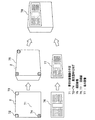
[複数の発光型RFIDタグを用いた画像の傾きの算出]
図6は、本発明の他の実施形態にかかわる拡張現実感による情報提示システムのシステム構成の一例を示す図であり、保守対象機器2に複数の発光型RFIDタグ1を貼付することで画像処理の負荷を低減する例を説明するために示した。
図6に沿って保守対象機器2に複数の発光型RFIDタグ1を貼付することで画像処理の負荷を低減する例を説明する。
この場合も保守作業員が携行するウエアラブルコンピュータは、図1に示す実施形態と同様である。ただし、ここでは、保守対象機器2に複数の発光型RFIDタグ61〜63が貼付されている。なお、貼付する発光型RFIDタグ61〜63の個数は、保守対象機器2の形状にもよるが、箱型の場合は、重ねて表示したい面に、3個の発光型RFIDタグ61〜63を貼付すれば目的は達せられる。
[Calculation of image tilt using multiple light emitting RFID tags]
FIG. 6 is a diagram showing an example of a system configuration of an information presentation system based on augmented reality according to another embodiment of the present invention. Image processing is performed by attaching a plurality of light emitting RFID tags 1 to a
An example of reducing the image processing load by attaching a plurality of light emitting RFID tags 1 to the
Also in this case, the wearable computer carried by the maintenance worker is the same as the embodiment shown in FIG. However, a plurality of light emitting RFID tags 61 to 63 are attached to the
具体的に、貼付されるそれぞれの発光型RFIDタグ1には、それぞれ固有の識別情報を書き込み、それぞれについて保守対象機器2およびその貼付位置とを対応付けて記憶装置6に記憶しておくものとする。
処理装置5から、R/W7を経由して発光型FIDタグ61〜63に送信される発光要求信号は、固有の識別情報を含んでいる。各発行型RFIDタグ61〜63は、予め自身に割付けられた識別情報と送られた識別情報とが一致した場合にのみ発光するため、処理装置5は、3個の発行型RFIDタグ61〜63を順次発光させることで保守対象機器2の表示面の向きを一意に特定することができる。保守対象機器2の表示面の向きを特定する方法は、図7を参照して後記する。
Specifically, specific identification information is written in each light emitting RFID tag 1 to be affixed, and the
The light emission request signal transmitted from the processing device 5 to the light emitting FID tags 61 to 63 via the R /
図7は、前記した本発明の他の実施形態にかかわる拡張現実感による情報提示システムの拡張現実感画像表示の一例を示す図である。具体的に、保守対象機器2平面への回路図の重ね合わせ表示の例が示されている。
図6を参照しつつ、図7に沿って本発明の他の実施形態にかかわる拡張現実感による情報提示システムの拡張現実感画像表示の一例を説明する。
図7において、保守対象機器2の平面71には、固有の識別情報を書き込んだ発光型RFIDタグ72〜74を貼付してある。処理装置5(表示制御部55)は、この保守対象機器2をカメラ3で撮影した画像75で、発光型RFIDタグ72〜74の画像75における座標と、実空間における相対座標とから、保守対象機器2の平面71上の座標の変換マトリクスを生成することができる。ここで、生成された変換マトリクスに基づき、記憶装置6から読み出された保守対象機器2の内部の回路図76を変形処理した回路図77を取得し、これを撮影した画像75に重ね合わせ処理すれば、現実空間の映像と合った表示画像78が得られる。
FIG. 7 is a diagram showing an example of an augmented reality image display of an information presentation system based on augmented reality according to another embodiment of the present invention described above. Specifically, an example of overlay display of a circuit diagram on the
With reference to FIG. 6, an example of the augmented reality image display of the information presentation system based on the augmented reality according to another embodiment of the present invention will be described with reference to FIG.
In FIG. 7, light emitting RFID tags 72 to 74 in which unique identification information is written are affixed to the
以上説明のように本発明の実施形態は、例えば、プラント内の機器・配管・計測器など保守作業に関係する保守対象機器2に対して発光型RFIDタグ1を装着し、保守作業員が携行するR/W7からの発信によって、情報提示を要する保守対象機器2に関係した発光型RFIDタグ1を選択的に発光させ、保守対象機器2の位置と方向を簡単な画像処理により検出可能としたものである。このため、処理装置5は、カメラ3からの画像を取り込み、発光している発光型RFIDタグ1の位置を計算し、その画像から計算した発光型RFIDタグ1の座標を基点とし、作業に関連した情報をCGに変換してHMD4等の表示装置に表示する構成とした。
As described above, in the embodiment of the present invention, for example, a light emitting RFID tag 1 is attached to a
前記した構成によれば、例えば、プラント内の機器や配管等、特徴点によって個々の保守対象機器2を区別しにくい物体を対象に、作業者の位置や姿勢の変化によって刻々と変化する撮影画像から、保守対象機器2の存在と、保守対象機器2の位置と方向を画像処理の負荷を抑えて高速に特定でき、物と情報の関係を可視化する拡張現実感を実現することができる。
According to the configuration described above, for example, a captured image that changes every moment according to a change in the position and posture of an operator, targeting an object that is difficult to distinguish the individual
なお、図4に示す、発光要求送信部51と、応答信号受信部52と、画像取込部53と、差分画像演算部54と、表示制御部55と、CG生成部56と、ガイド情報生成部57のそれぞれが持つ機能は、具体的には、処理装置5が、周辺装置として接続されるカメラ3、HMD4、R/W7、入力装置8を使用し、記憶装置6に記録されたプログラムを逐次読み出し、実行することで実現されるものである。なお、前記したプログラムの中にはOS(Operating System)、あるいは、通信回線を介してダウンロードされるプログラムデータも含まれるものとする。
Note that the light emission request transmission unit 51, the response
1 発光型RFIDタグ
2 保守対象機器
3 撮影装置(カメラ)
4 表示装置(HMD:ヘッドマウントディスプレイ)
5 情報提示装置(処理装置)
6 記憶装置
7 リーダ/ライタ(R/W)
8 入力装置
51 発光要求送信部
52 応答信号受信部
53 画像取込部
54 差分画像演算部
55 表示制御部
56 CG生成部
57 ガイド情報生成部
DESCRIPTION OF SYMBOLS 1 Light emission
4. Display device (HMD: head mounted display)
5 Information presentation device (processing device)
6
DESCRIPTION OF
Claims (7)
前記発光型RFIDタグとはリーダライタを介して接続され、少なくとも撮影装置、表示装置、記憶装置および処理装置を備える情報提示装置とを含んで成る拡張現実感による情報提示システムであって、
前記処理装置は、前記記憶装置から前記発光型RFIDタグを一意に特定する識別情報を読み取り、前記発光型RFIDタグに対して前記識別情報を含む発光要求信号を送信する機能を備え、
前記発光型RFIDタグは、自身に書き込まれた固有の識別情報と、前記処理装置から受信した識別情報とを比較し、一致したときに所定の時間間隔で間欠的に発光を行うとともに、前記処理装置に応答信号を送信する機能を備え、
前記処理装置は、前記撮影装置を介して、予め調整された時間間隔で発光前と発光中に取り込まれた撮影画像の差分を演算し、当該演算の結果得られる差分画像から前記発光型RFIDタグの発光位置を算出し、前記記憶装置から前記情報を表示したい保守対象機器に関連する表示情報を取得するとともに、その表示情報の表示位置を、前記発光位置を基点とした相対位置座標として算出し、前記表示情報をコンピュータグラフィックスに変換して前記表示装置に表示することを特徴とする拡張現実感による情報提示システム。 A light emitting RFID tag that is attached to a maintenance target device for which information is to be displayed,
The light emitting RFID tag is an information presentation system based on augmented reality that is connected via a reader / writer and includes at least an information presentation device including a photographing device, a display device, a storage device, and a processing device,
The processing device has a function of reading identification information for uniquely identifying the light emitting RFID tag from the storage device, and transmitting a light emission request signal including the identification information to the light emitting RFID tag,
The light emitting RFID tag compares the unique identification information written in itself with the identification information received from the processing device, and emits light intermittently at a predetermined time interval when they match. It has a function to send a response signal to the device,
The processing device calculates a difference between a photographed image captured before and during light emission at a time interval adjusted in advance through the photographing device, and the light emitting RFID tag is obtained from the difference image obtained as a result of the computation. The display position related to the maintenance target device for which the information is to be displayed is acquired from the storage device, and the display position of the display information is calculated as relative position coordinates based on the light emission position. An information presentation system based on augmented reality, wherein the display information is converted into computer graphics and displayed on the display device.
前記発光型RFIDタグとはリーダライタを介して接続され、少なくとも撮影装置、表示装置、記憶装置および処理装置を備える情報提示装置とを含んで成る情報提示システムにおける拡張現実感による情報提示方法であって、
前記処理装置が、
前記記憶装置から前記発行型RFIDタグを一意に特定する識別情報を読み取り、前記発光型RFIDタグに対して前記識別情報を含む発光要求信号を送信し、
前記発光型RFIDタグが、
自身に書き込まれた固有の識別情報と、前記処理装置から受信した識別情報とを比較し、一致したときに所定の時間間隔で間欠的に発光を行うとともに、前記処理装置に応答信号を送信し、
前記処理装置が、
前記撮影装置を介して、予め調整された時間間隔で発光前と発光中に取り込まれる撮影画像の差分を演算し、当該演算の結果得られる差分画像から前記発光型RFIDタグの発光位置を算出し、
前記処理装置が、
前記記憶装置から前記情報を表示したい保守対象機器に関連する表示情報を取得するとともに、その表示情報の表示位置を、前記発光位置を基点とした相対位置座標として算出し、前記表示情報をコンピュータグラフィックスに変換して前記表示装置に表示すること、
を有することを特徴とする拡張現実感による情報提示方法。 A light emitting RFID tag that is attached to a maintenance target device for which information is to be displayed,
The light emitting RFID tag is an information presentation method based on augmented reality in an information presentation system that is connected via a reader / writer and includes at least an information presentation device including a photographing device, a display device, a storage device, and a processing device. And
The processing device is
Read identification information that uniquely identifies the issuing RFID tag from the storage device, and send a light emission request signal including the identification information to the light emitting RFID tag,
The light emitting RFID tag is
The unique identification information written in itself is compared with the identification information received from the processing device, and when they match, light is emitted intermittently at a predetermined time interval and a response signal is transmitted to the processing device. ,
The processing device is
The difference between the captured images captured before and during the light emission is calculated at a preset time interval via the imaging device, and the light emission position of the light emitting RFID tag is calculated from the difference image obtained as a result of the calculation. ,
The processing device is
The display information related to the maintenance target device for which the information is to be displayed is acquired from the storage device, the display position of the display information is calculated as relative position coordinates based on the light emission position, and the display information is calculated by computer graphics. Converting it into a display on the display device,
An information presentation method using augmented reality, characterized by comprising:
前記記憶装置から前記発行型RFIDタグを一意に特定する識別情報を読み取り、前記発光型RFIDタグに対して前記識別情報を含む発光要求信号を送信する発光要求送信部と、
前記発光型RFIDタグから応答信号を受信したとき、前記撮影装置を介して発光前と発光中に取り込まれる撮影画像の差分を演算し、当該演算の結果得られる差分画像から前記発光型RFIDタグの発光位置を算出する差分画像演算部と、
前記記憶装置から前記保守対象機器に関連する表示情報を取得するとともに、その表示情報の表示位置を、前記発光位置を基点とした相対位置座標として算出し、前記表示情報をコンピュータグラフィックスに変換して前記表示装置に表示する表示制御部と、
を備えたことを特徴とする拡張現実感による情報提示装置。 Based on augmented reality, which is connected to a light-emitting RFID tag that is attached to a maintenance target device that wants to display information and that is attached to a maintenance target device via a reader / writer, and includes a photographing device, a display device, and a storage device An information presentation device,
A light emission request transmitter that reads identification information for uniquely identifying the issuing RFID tag from the storage device, and transmits a light emission request signal including the identification information to the light emitting RFID tag;
When a response signal is received from the light emitting RFID tag, the difference between the captured images captured before and during the light emission is calculated via the imaging device, and the difference between the light emitting RFID tag and the difference image obtained as a result of the calculation is calculated. A difference image calculation unit for calculating a light emission position;
The display information related to the maintenance target device is acquired from the storage device, the display position of the display information is calculated as relative position coordinates based on the light emission position, and the display information is converted into computer graphics. Display control unit for displaying on the display device,
An information presentation device with augmented reality characterized by comprising:
前記発光型RFIDタグから応答信号を受信できなかったとき、もしくは前記応答信号を受信しても前記情報を表示したい保守対象機器が視野の外にあると判定されたときに、前記情報を表示したい保守対象機器に辿り着くために必要なガイド情報を生成し、表示することを特徴とする請求項3に記載の拡張現実感による情報提示装置。 The display control unit
When the response signal cannot be received from the light emitting RFID tag, or when it is determined that the maintenance target device for which the information is to be displayed is received out of the field of view even when the response signal is received, the information is to be displayed. 4. The information presentation apparatus with augmented reality according to claim 3, wherein guide information necessary for reaching the maintenance target device is generated and displayed.
前記情報を表示したい保守対象機器に装着された、それぞれに固有の識別情報が書き込まれた複数の発光型RFIDタグに対し、順次発光要求を送信することを特徴とする請求項3または請求項4に記載の拡張現実感による情報提示装置。 The light emission request transmitter is
5. The light emission request is sequentially transmitted to a plurality of light emitting RFID tags, each of which is attached to a maintenance target device for which the information is to be displayed and in which unique identification information is written, respectively. An information presentation device based on augmented reality described in 1.
前記撮影装置を介して取り込まれた前記表示したい保守対象機器の画像上で、前記それぞれの発光型RFIDタグの画像における基点位置と実空間の相対座標とから前記保守対象機器の平面上における座標の変換マトリクスを生成し、当該変換マトリクスに従い前記保守対象機器に関連する表示情報を変換し、前記取り込まれた保守対象機器の画像と重ね合わせて表示することを特徴とする請求項3から請求項5のいずれか一項に記載の拡張現実感による情報提示装置。 The display control unit
On the image of the maintenance target device to be displayed captured via the imaging device, the coordinates of the coordinate on the plane of the maintenance target device are determined from the base point position in the image of each light emitting RFID tag and the relative coordinates in the real space. 6. A conversion matrix is generated, display information related to the maintenance target device is converted in accordance with the conversion matrix, and is displayed superimposed on the captured image of the maintenance target device. The information presentation apparatus by the augmented reality as described in any one of the above.
前記記憶装置から前記発行型RFIDタグを一意に特定する識別情報を読み取り、前記発光型RFIDタグに対して前記識別情報を含む発光要求信号を送信する処理と、
前記発光型RFIDタグから応答信号を受信したとき、前記撮影装置を介して発光前と発光中に取り込まれる撮影画像の差分を演算し、当該演算の結果得られる差分画像から前記発光型RFIDタグの発光位置を算出する処理と、
前記記憶装置から前記保守対象機器に関連する表示情報を取得するとともに、その表示情報の表示位置を、前記発光位置を基点とした相対位置座標として取得し、前記表示情報をコンピュータグラフィックスに変換して前記表示装置に表示する処理と、
をコンピュータに実行させるコンピュータプログラム。 Augmented reality, which is connected to a light emitting RFID tag that is attached to a maintenance target device for which information is to be displayed and is attached via a reader / writer, and that includes a photographing device, a display device, and a storage device. A computer program used for an information presentation device according to
A process of reading identification information for uniquely identifying the issuing RFID tag from the storage device, and transmitting a light emission request signal including the identification information to the light emitting RFID tag;
When a response signal is received from the light emitting RFID tag, the difference between the captured images captured before and during the light emission is calculated via the imaging device, and the difference between the light emitting RFID tag and the difference image obtained as a result of the calculation is calculated. A process of calculating the light emission position;
The display information related to the maintenance target device is acquired from the storage device, the display position of the display information is acquired as relative position coordinates based on the light emission position, and the display information is converted into computer graphics. Processing to display on the display device,
A computer program that causes a computer to execute.
Priority Applications (1)
| Application Number | Priority Date | Filing Date | Title |
|---|---|---|---|
| JP2005197999A JP2007018188A (en) | 2005-07-06 | 2005-07-06 | System, method and apparatus for information presentation through extended sense of reality, and computer program |
Applications Claiming Priority (1)
| Application Number | Priority Date | Filing Date | Title |
|---|---|---|---|
| JP2005197999A JP2007018188A (en) | 2005-07-06 | 2005-07-06 | System, method and apparatus for information presentation through extended sense of reality, and computer program |
Publications (1)
| Publication Number | Publication Date |
|---|---|
| JP2007018188A true JP2007018188A (en) | 2007-01-25 |
Family
ID=37755319
Family Applications (1)
| Application Number | Title | Priority Date | Filing Date |
|---|---|---|---|
| JP2005197999A Pending JP2007018188A (en) | 2005-07-06 | 2005-07-06 | System, method and apparatus for information presentation through extended sense of reality, and computer program |
Country Status (1)
| Country | Link |
|---|---|
| JP (1) | JP2007018188A (en) |
Cited By (16)
| Publication number | Priority date | Publication date | Assignee | Title |
|---|---|---|---|---|
| JP2009129021A (en) * | 2007-11-20 | 2009-06-11 | Ntt Docomo Inc | Information input system and information input method |
| JP2009168488A (en) * | 2008-01-11 | 2009-07-30 | Toyota Motor Corp | Position information acquisition apparatus, position estimation apparatus, and moving body |
| JP2009187499A (en) * | 2008-02-08 | 2009-08-20 | Fujitsu Fsas Inc | Maintenance management method and maintenance management system |
| JP2009184781A (en) * | 2008-02-06 | 2009-08-20 | Nippon Telegr & Teleph Corp <Ntt> | File cabinet management system and file cabinet management method |
| JP2010527722A (en) * | 2007-05-31 | 2010-08-19 | ソニー コンピュータ エンタテインメント ヨーロッパ リミテッド | Entertainment system and method |
| WO2010113466A1 (en) * | 2009-03-31 | 2010-10-07 | 日本電気株式会社 | System and method for virtual machine management, control device, method and program |
| JP2012043396A (en) * | 2010-08-13 | 2012-03-01 | Hyundai Motor Co Ltd | System and method for managing vehicle consumables using augmented reality |
| JP2012198791A (en) * | 2011-03-22 | 2012-10-18 | Japan Research Institute Ltd | Maintenance information display device, maintenance information display method and program |
| JP2013506218A (en) * | 2009-10-01 | 2013-02-21 | オラワークス・インコーポレイテッド | Method for performing visual search based on movement or posture of terminal, terminal and computer-readable recording medium |
| JP2014235704A (en) * | 2013-06-05 | 2014-12-15 | 富士機械製造株式会社 | Board production assist system |
| JP2018109855A (en) * | 2016-12-29 | 2018-07-12 | 富士通株式会社 | Information processing apparatus, device and method for determining whether data is correct or not |
| JP2018205974A (en) * | 2017-06-01 | 2018-12-27 | 株式会社日立ドキュメントソリューションズ | Space display device and space display method |
| JP2019191809A (en) * | 2018-04-23 | 2019-10-31 | オムロン株式会社 | Tag communication device and method for controlling the same, and control program |
| KR20210007890A (en) * | 2019-07-10 | 2021-01-20 | 제브라 테크놀로지스 코포레이션 | An alternative method to interact with a user interface using standard barcode scanners paired up with an augmented reality heads up display |
| US11003911B2 (en) | 2017-02-28 | 2021-05-11 | Nec Corporation | Inspection assistance device, inspection assistance method, and recording medium |
| JP2021157694A (en) * | 2020-03-30 | 2021-10-07 | Sppテクノロジーズ株式会社 | Portable terminal, method, and program |
-
2005
- 2005-07-06 JP JP2005197999A patent/JP2007018188A/en active Pending
Cited By (20)
| Publication number | Priority date | Publication date | Assignee | Title |
|---|---|---|---|---|
| JP2010527722A (en) * | 2007-05-31 | 2010-08-19 | ソニー コンピュータ エンタテインメント ヨーロッパ リミテッド | Entertainment system and method |
| JP2009129021A (en) * | 2007-11-20 | 2009-06-11 | Ntt Docomo Inc | Information input system and information input method |
| JP2009168488A (en) * | 2008-01-11 | 2009-07-30 | Toyota Motor Corp | Position information acquisition apparatus, position estimation apparatus, and moving body |
| JP2009184781A (en) * | 2008-02-06 | 2009-08-20 | Nippon Telegr & Teleph Corp <Ntt> | File cabinet management system and file cabinet management method |
| JP2009187499A (en) * | 2008-02-08 | 2009-08-20 | Fujitsu Fsas Inc | Maintenance management method and maintenance management system |
| JP5382112B2 (en) * | 2009-03-31 | 2014-01-08 | 日本電気株式会社 | Virtual machine management system and method, and control apparatus, method and program |
| WO2010113466A1 (en) * | 2009-03-31 | 2010-10-07 | 日本電気株式会社 | System and method for virtual machine management, control device, method and program |
| JPWO2010113466A1 (en) * | 2009-03-31 | 2012-10-04 | 日本電気株式会社 | Virtual machine management system and method, and control apparatus, method and program |
| US8924968B2 (en) | 2009-03-31 | 2014-12-30 | Nec Corporation | System and method of managing virtual machine, and control apparatus, method and program |
| JP2013506218A (en) * | 2009-10-01 | 2013-02-21 | オラワークス・インコーポレイテッド | Method for performing visual search based on movement or posture of terminal, terminal and computer-readable recording medium |
| JP2012043396A (en) * | 2010-08-13 | 2012-03-01 | Hyundai Motor Co Ltd | System and method for managing vehicle consumables using augmented reality |
| JP2012198791A (en) * | 2011-03-22 | 2012-10-18 | Japan Research Institute Ltd | Maintenance information display device, maintenance information display method and program |
| JP2014235704A (en) * | 2013-06-05 | 2014-12-15 | 富士機械製造株式会社 | Board production assist system |
| JP2018109855A (en) * | 2016-12-29 | 2018-07-12 | 富士通株式会社 | Information processing apparatus, device and method for determining whether data is correct or not |
| US11003911B2 (en) | 2017-02-28 | 2021-05-11 | Nec Corporation | Inspection assistance device, inspection assistance method, and recording medium |
| JP2018205974A (en) * | 2017-06-01 | 2018-12-27 | 株式会社日立ドキュメントソリューションズ | Space display device and space display method |
| JP2019191809A (en) * | 2018-04-23 | 2019-10-31 | オムロン株式会社 | Tag communication device and method for controlling the same, and control program |
| KR20210007890A (en) * | 2019-07-10 | 2021-01-20 | 제브라 테크놀로지스 코포레이션 | An alternative method to interact with a user interface using standard barcode scanners paired up with an augmented reality heads up display |
| KR102228340B1 (en) | 2019-07-10 | 2021-03-15 | 제브라 테크놀로지스 코포레이션 | An alternative method to interact with a user interface using standard barcode scanners paired up with an augmented reality heads up display |
| JP2021157694A (en) * | 2020-03-30 | 2021-10-07 | Sppテクノロジーズ株式会社 | Portable terminal, method, and program |
Similar Documents
| Publication | Publication Date | Title |
|---|---|---|
| JP2007018188A (en) | System, method and apparatus for information presentation through extended sense of reality, and computer program | |
| US11481999B2 (en) | Maintenance work support system and maintenance work support method | |
| US9448758B2 (en) | Projecting airplane location specific maintenance history using optical reference points | |
| KR102321325B1 (en) | Method, method, and apparatus for determining pose information for augmented reality display | |
| JP5055516B2 (en) | System and method for displaying device maintenance and operation instructions using augmented reality | |
| JP4642538B2 (en) | Image processing method and image processing apparatus | |
| US10481679B2 (en) | Method and system for optical-inertial tracking of a moving object | |
| US20190347860A1 (en) | Augmented reality-based system | |
| CN104897091A (en) | Articulated arm coordinate measuring machine | |
| TW201142745A (en) | Information processing apparatus, information processing system, and information processing method | |
| JP2007071782A (en) | System for measuring position attitude and method of measuring, same and control program | |
| JP2007064684A (en) | Marker arrangement assisting method and device therefor | |
| KR102104326B1 (en) | Maintenance training system and method based on augmented reality | |
| EP2876624A1 (en) | Maintenance assistant system | |
| US20190377330A1 (en) | Augmented Reality Systems, Methods And Devices | |
| US20200090365A1 (en) | Method of device tracking, terminal device, and storage medium | |
| CN108257177A (en) | Alignment system and method based on space identification | |
| JP6380647B2 (en) | Information providing method, information providing program, information providing apparatus, information processing apparatus, and information providing system | |
| Nakazato et al. | Wearable augmented reality system using invisible visual markers and an IR camera | |
| JP2006252468A (en) | Image processing method and image processing system | |
| JP6295296B2 (en) | Complex system and target marker | |
| CN112074705A (en) | Method and system for optical inertial tracking of moving object | |
| JP7109395B2 (en) | WORK SUPPORT SYSTEM, WORK SUPPORT DEVICE, AND WORK SUPPORT METHOD | |
| WO2017149120A1 (en) | Method for maintenance support and maintenance support system | |
| JPH11351826A (en) | Camera position identifier |