JP2007017289A - Non-destructive inspection system and non-destructive inspection method of fss sandwich panel - Google Patents
Non-destructive inspection system and non-destructive inspection method of fss sandwich panel Download PDFInfo
- Publication number
- JP2007017289A JP2007017289A JP2005199180A JP2005199180A JP2007017289A JP 2007017289 A JP2007017289 A JP 2007017289A JP 2005199180 A JP2005199180 A JP 2005199180A JP 2005199180 A JP2005199180 A JP 2005199180A JP 2007017289 A JP2007017289 A JP 2007017289A
- Authority
- JP
- Japan
- Prior art keywords
- fss
- sandwich panel
- radio wave
- frequency
- radio
- Prior art date
- Legal status (The legal status is an assumption and is not a legal conclusion. Google has not performed a legal analysis and makes no representation as to the accuracy of the status listed.)
- Pending
Links
- 238000007689 inspection Methods 0.000 title claims abstract description 94
- 230000001066 destructive effect Effects 0.000 title claims abstract description 20
- 238000000034 method Methods 0.000 title claims description 24
- 230000007547 defect Effects 0.000 claims abstract description 43
- 230000001678 irradiating effect Effects 0.000 claims abstract description 10
- 238000005259 measurement Methods 0.000 claims description 53
- 230000005540 biological transmission Effects 0.000 claims description 30
- 238000002834 transmittance Methods 0.000 claims description 10
- 238000002310 reflectometry Methods 0.000 abstract description 2
- 230000035699 permeability Effects 0.000 abstract 1
- 238000001514 detection method Methods 0.000 description 27
- 239000011347 resin Substances 0.000 description 21
- 229920005989 resin Polymers 0.000 description 21
- XEEYBQQBJWHFJM-UHFFFAOYSA-N Iron Chemical compound [Fe] XEEYBQQBJWHFJM-UHFFFAOYSA-N 0.000 description 20
- 239000012792 core layer Substances 0.000 description 19
- 238000004088 simulation Methods 0.000 description 18
- 239000010410 layer Substances 0.000 description 16
- 238000013461 design Methods 0.000 description 13
- 229910052742 iron Inorganic materials 0.000 description 10
- 239000011162 core material Substances 0.000 description 6
- 238000012360 testing method Methods 0.000 description 6
- 238000002474 experimental method Methods 0.000 description 5
- 239000002344 surface layer Substances 0.000 description 4
- 238000012795 verification Methods 0.000 description 4
- 239000000463 material Substances 0.000 description 3
- 238000004364 calculation method Methods 0.000 description 2
- 230000000694 effects Effects 0.000 description 2
- 239000006260 foam Substances 0.000 description 2
- 239000006261 foam material Substances 0.000 description 2
- 238000009413 insulation Methods 0.000 description 2
- 230000035945 sensitivity Effects 0.000 description 2
- RYGMFSIKBFXOCR-UHFFFAOYSA-N Copper Chemical compound [Cu] RYGMFSIKBFXOCR-UHFFFAOYSA-N 0.000 description 1
- 244000027321 Lychnis chalcedonica Species 0.000 description 1
- 229910052802 copper Inorganic materials 0.000 description 1
- 239000010949 copper Substances 0.000 description 1
- 238000010586 diagram Methods 0.000 description 1
- 238000005516 engineering process Methods 0.000 description 1
- 238000000605 extraction Methods 0.000 description 1
- 239000003365 glass fiber Substances 0.000 description 1
- 230000012447 hatching Effects 0.000 description 1
- 238000004519 manufacturing process Methods 0.000 description 1
- 238000000691 measurement method Methods 0.000 description 1
- 239000002184 metal Substances 0.000 description 1
- 229910052751 metal Inorganic materials 0.000 description 1
- 238000012545 processing Methods 0.000 description 1
- 239000011208 reinforced composite material Substances 0.000 description 1
Images


Landscapes
- Investigating Or Analyzing Materials By The Use Of Ultrasonic Waves (AREA)
Abstract
Description
本発明は、特定の周波数の電波を反射又は透過させる周波数選択板(FSS:Frequency Selective Surface)が挿入された積層板(FSSサンドイッチパネル)の内部欠陥を検査するFSSサンドイッチパネルの非破壊検査装置及び非破壊検査方法に関する。 The present invention relates to a non-destructive inspection apparatus for an FSS sandwich panel for inspecting internal defects of a laminated plate (FSS sandwich panel) in which a frequency selective plate (FSS: Frequency Selective Surface) that reflects or transmits a radio wave having a specific frequency is inserted. It relates to a nondestructive inspection method.
従来、被検体に対して超音波探傷,X線探傷又は赤外線探傷を行い当該被検体の欠陥を検知する非破壊検査装置及び非破壊検査方法が知られている。 Conventionally, a nondestructive inspection apparatus and a nondestructive inspection method for detecting a defect of the subject by performing ultrasonic testing, X-ray testing, or infrared testing on the subject are known.
例えば、超音波探傷やX線探傷を行う非破壊検査装置及び非破壊検査方法としては下記の特許文献1に開示されており、赤外線探傷を行う非破壊検査装置及び非破壊検査方法としては下記の特許文献2に開示されている。
For example, a nondestructive inspection apparatus and a nondestructive inspection method for performing ultrasonic flaw detection and X-ray flaw detection are disclosed in the following
ここで、赤外線探傷は、被検体の表層の欠陥を非破壊検査するものである。また、超音波探傷は、発泡材コアやハニカムコア等の音波伝播を著しく減衰するコア材が遮音層になってしまうので、このようなコア材を使用したサンドイッチパネルについてはその表層しか非破壊検査することができない。これが為、これら超音波探傷や赤外線探傷は、その表層の異物や樹脂充填不足箇所(レジンスターブ)を検知することはできるが、その裏面側については例えば被検体を裏返す等しなければ検査することができない。即ち、この超音波探傷や赤外線探傷では、一度に裏面まで検査することができない。更に、被検体がFSSサンドイッチパネルの如き厚みを有するものであれば、その表層以外の内部の異物や樹脂充填不足箇所等の欠陥を検知することができない。また、赤外線探傷については、超音波探傷よりも感度が低く、表面の欠陥すら感度良く検知できない場合もある。 Here, infrared flaw detection is a non-destructive inspection for defects on the surface layer of a subject. In addition, ultrasonic flaw detection uses a core material that significantly attenuates sound wave propagation, such as a foam core and honeycomb core, as a sound insulation layer. For sandwich panels that use such a core material, only the surface layer is subjected to nondestructive inspection. Can not do it. For this reason, these ultrasonic flaw detection and infrared flaw detection can detect foreign matters on the surface layer and resin-filled portions (resin stave), but the back side should be inspected unless the subject is turned over, for example. I can't. That is, the ultrasonic inspection or infrared inspection cannot inspect the back surface at once. Furthermore, if the specimen has a thickness such as an FSS sandwich panel, it is not possible to detect defects such as internal foreign matters other than the surface layer and insufficiently filled portions of the resin. Infrared flaw detection is less sensitive than ultrasonic flaw detection, and even surface defects may not be detected with good sensitivity.
一方、X線探傷については、表面から裏面までの間の異物を一度に検知することはできるが、樹脂充填不足箇所については検知することができない。 On the other hand, for X-ray flaw detection, foreign matter between the front surface and the back surface can be detected at one time, but a resin-filled insufficient portion cannot be detected.
尚、FSSサンドイッチパネルとは、例えば、発泡材コアやハニカムコア等の遮音性の高いコア層と、このコア層の両面又は一方の面に積層した周波数選択板と、これら各周波数選択板又は周波数選択板及びコア層の他方の面に積層した誘電体層とで構成されたものである。これが為、従来の超音波探傷,赤外線探傷又はX線探傷を行う非破壊検査装置及び非破壊検査方法では、FSSサンドイッチパネル全体の異物や樹脂充填不足箇所等の欠陥(X線探傷の場合であれば異物を除く)を検知することができない。 Note that the FSS sandwich panel includes, for example, a core layer having high sound insulation such as a foam core and a honeycomb core, a frequency selection plate laminated on both sides or one side of the core layer, and each of these frequency selection plates or frequencies. The selection plate and the dielectric layer laminated on the other surface of the core layer. For this reason, the conventional nondestructive inspection apparatus and nondestructive inspection method for ultrasonic flaw detection, infrared flaw detection, or X-ray flaw detection are free from defects such as foreign matter on the entire FSS sandwich panel and areas where resin filling is insufficient (in the case of X-ray flaw detection). Cannot be detected).
そこで、本発明は、かかる従来例の有する不都合を改善し、FSSサンドイッチパネルにおける表面から裏面までの間の異物や樹脂充填不足箇所等の欠陥を一度に検知可能なFSSサンドイッチパネルの非破壊検査装置及び非破壊検査方法を提供することを、その目的とする。 Therefore, the present invention improves the inconvenience of the conventional example, and the FSS sandwich panel non-destructive inspection apparatus capable of detecting foreign matters between the front surface and the back surface of the FSS sandwich panel and defects such as insufficient resin filling at a time. It is another object of the present invention to provide a nondestructive inspection method.
上記目的を達成する為、請求項1記載の発明では、特定の周波数の電波を反射又は透過させる周波数選択板が挿入されたFSSサンドイッチパネルの内部欠陥を検査するFSSサンドイッチパネルの非破壊検査装置において、そのFSSサンドイッチパネルの共振周波数よりも高く、且つ、そのFSSサンドイッチパネルにおける反射率と透過率の変動が小さい範囲内の周波数の電波を当該FSSサンドイッチパネルに照射する電波照射手段と、そのFSSサンドイッチパネルを透過した又は当該FSSサンドイッチパネルから反射した電波を受信する電波受信手段と、その電波照射手段から照射された電波と電波受信手段が受信した電波とからFSSサンドイッチパネルにおける電波の透過性能又は反射性能を測定する測定手段とを備えている。 In order to achieve the above object, according to the first aspect of the present invention, there is provided a nondestructive inspection apparatus for an FSS sandwich panel for inspecting an internal defect of an FSS sandwich panel in which a frequency selection plate for reflecting or transmitting a radio wave having a specific frequency is inserted. A radio wave irradiating means for irradiating the FSS sandwich panel with radio waves having a frequency higher than the resonance frequency of the FSS sandwich panel and having a small variation in reflectance and transmittance in the FSS sandwich panel, and the FSS sandwich panel Radio wave reception means for receiving radio waves transmitted through the panel or reflected from the FSS sandwich panel, radio wave transmission performance or reflection in the FSS sandwich panel from radio waves irradiated from the radio wave irradiation means and radio waves received by the radio wave reception means With measuring means for measuring performance That.
また、上記目的を達成する為、請求項3記載の発明では、特定の周波数の電波を反射又は透過させる周波数選択板が挿入されたFSSサンドイッチパネルの内部欠陥を検査するFSSサンドイッチパネルの非破壊検査方法において、そのFSSサンドイッチパネルの共振周波数よりも高く、且つ、そのFSSサンドイッチパネルにおける反射率と透過率の変動が小さい範囲内の周波数の電波を当該FSSサンドイッチパネルに照射する工程と、そのFSSサンドイッチパネルを透過した又は当該FSSサンドイッチパネルから反射した電波を受信する工程と、そのFSSサンドイッチパネルに照射された電波と当該FSSサンドイッチパネルからの透過電波又は反射電波とから当該FSSサンドイッチパネルにおける電波の透過性能又は反射性能を測定する工程とを有している。 In order to achieve the above object, according to the third aspect of the invention, a nondestructive inspection of an FSS sandwich panel for inspecting an internal defect of an FSS sandwich panel in which a frequency selection plate for reflecting or transmitting a radio wave of a specific frequency is inserted. A method of irradiating the FSS sandwich panel with radio waves having a frequency higher than the resonance frequency of the FSS sandwich panel and within a range in which fluctuations in reflectance and transmittance of the FSS sandwich panel are small; Radio wave transmission in the FSS sandwich panel from the step of receiving the radio wave transmitted through the panel or reflected from the FSS sandwich panel, the radio wave irradiated on the FSS sandwich panel and the transmitted radio wave or reflected radio wave from the FSS sandwich panel Performance or reflection And a step of measuring the ability.
例えば、その請求項1記載のFSSサンドイッチパネルの非破壊検査装置の測定手段は、請求項2記載の発明の如く、電波の透過性能又は反射性能として、電波照射手段から照射された電波と電波受信手段が受信した電波とからFSSサンドイッチパネルにおける電波透過性能又は電波反射性能を算出するよう構成する。
For example, the measurement means of the FSS sandwich panel non-destructive inspection apparatus according to
また、例えば、その請求項3記載のFSSサンドイッチパネルの非破壊検査方法において電波の透過性能又は反射性能を測定する際には、請求項4記載の発明の如く、FSSサンドイッチパネルに照射された電波と当該FSSサンドイッチパネルからの透過電波又は反射電波とから当該FSSサンドイッチパネルにおける電波透過性能又は電波反射性能を算出する。 Further, for example, when measuring radio wave transmission performance or reflection performance in the non-destructive inspection method for an FSS sandwich panel according to claim 3, the radio wave irradiated to the FSS sandwich panel as in the invention according to claim 4. Then, the radio wave transmission performance or radio wave reflection performance of the FSS sandwich panel is calculated from the transmitted radio wave or reflected radio wave from the FSS sandwich panel.
この請求項1,2,3又は4に記載の発明によれば、FSSサンドイッチパネルに対して上述した範囲内の周波数の電波を照射し、そのFSSサンドイッチパネルにおける電波の透過性能又は反射性能を観ることによって、そのFSSサンドイッチパネルの表面から裏面までの間の異物や樹脂充填不足箇所等の欠陥を検知することができる。
According to the invention described in
本発明に係るFSSサンドイッチパネルの非破壊検査装置及び非破壊検査方法は、FSSサンドイッチパネルの共振周波数よりも高く、且つ、そのFSSサンドイッチパネルにおける反射率と透過率の変動が小さい範囲内の周波数の電波を当該FSSサンドイッチパネルに照射することによって、従来の超音波探傷,赤外線探傷又はX線探傷のみでは一度に検知し得なかったFSSサンドイッチパネルにおける表面から裏面までの間の異物や樹脂充填不足箇所等の欠陥を一度に検知することができる。 The non-destructive inspection apparatus and non-destructive inspection method for an FSS sandwich panel according to the present invention has a frequency higher than the resonance frequency of the FSS sandwich panel and a frequency within a range in which the fluctuations in reflectance and transmittance of the FSS sandwich panel are small. By irradiating the FSS sandwich panel with radio waves, foreign matter between the front surface and the back surface of the FSS sandwich panel that could not be detected at a time only by conventional ultrasonic flaw detection, infrared flaw detection, or X-ray flaw detection Etc. can be detected at a time.
以下に、本発明に係るFSSサンドイッチパネルの非破壊検査装置及び非破壊検査方法の実施例を図面に基づいて詳細に説明する。尚、この実施例によりこの発明が限定されるものではない。 Embodiments of a nondestructive inspection apparatus and a nondestructive inspection method for an FSS sandwich panel according to the present invention will be described below in detail with reference to the drawings. The present invention is not limited to the embodiments.
本発明に係るFSSサンドイッチパネルの非破壊検査装置及び非破壊検査方法の実施例1を図1から図10に基づいて説明する。 A first embodiment of a nondestructive inspection apparatus and a nondestructive inspection method for an FSS sandwich panel according to the present invention will be described with reference to FIGS.
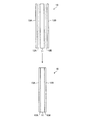
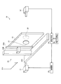
最初に、本実施例1における非破壊検査装置の被検体たるFSSサンドイッチパネル10を図1に基づき説明する。
First, the FSS
このFSSサンドイッチパネル10は、矩形のコア層11と、このコア層11の両面に積層した矩形の第1及び第2の周波数選択板12A,12Bと、これら第1及び第2の周波数選択板12A,12Bの夫々に積層した矩形の第1及び第2の誘電体層13A,13Bとで構成されている。
The FSS
例えば、そのコア層11としては発泡材を用いる一方、その第1及び第2の誘電体層13A,13BとしてはGFRP(ガラス繊維強化複合材料)を用いる。
For example, a foam material is used as the
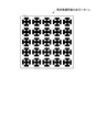
また、第1及び第2の周波数選択板12A,12Bには例えば銅線等の金属線からなる複数のクロスダイポール型等の素子パターンが格子状に配置されており、これにより特定の周波数の電波を反射又は透過させる。本実施例1にあっては、図2に示すエルサレムクロス型の素子パターンを用いている。
The first and second
このような第1及び第2の周波数選択板12A,12Bが挿入されているFSSサンドイッチパネル10においては、所望の共振効果を得る設計周波数(共振周波数)と同等の周波数の電波を反射又は透過させる。
In the
一方、このFSSサンドイッチパネル10に照射される電波の周波数に拘わらず、このFSSサンドイッチパネル10を透過した電波又はFSSサンドイッチパネル10から反射した電波は、FSSサンドイッチパネル10の仕様毎の固有の値として検出することができる。即ち、このFSSサンドイッチパネル10に何ら欠陥がなければ、このFSSサンドイッチパネル10は、FSSサンドイッチパネル10の仕様毎に固有の電波の透過性能又は反射性能を発揮する。これが為、仮にFSSサンドイッチパネル10の内部に異物や欠損等の欠陥がある場合には、その固有の値として検出されるべき反射又は透過した電波がFSSサンドイッチパネル10の仕様に応じた正規の値として検出されなくなる。
On the other hand, regardless of the frequency of the radio wave irradiated to the
そこで、本実施例1にあっては、かかる特性を利用してFSSサンドイッチパネル10の非破壊検査を行う。
Therefore, in the first embodiment, nondestructive inspection of the
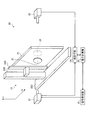
次に、本実施例1の非破壊検査装置の構成を図3に基づき説明する。 Next, the configuration of the nondestructive inspection apparatus according to the first embodiment will be described with reference to FIG.
その図3の符号20は、本実施例1の非破壊検査装置を示す。本実施例1の非破壊検査装置20には、FSSサンドイッチパネル10に対して電波(ミリ波)を照射する電波照射手段21と、この電波照射手段21の電波照射部に対向して配置された電波受信部を有する電波受信手段22と、その電波照射手段21と電波受信手段22との間でFSSサンドイッチパネル10を図3に示すXY方向へと移動させる被検体移動手段23と、その電波受信手段22が受信した電波を測定点毎の測定データとして取り込んで測定結果を算出する測定手段24とが設けられている。
ここで、その被検体移動手段23は、FSSサンドイッチパネル10を保持する保持具23Aと、この保持具23Aを図3に示すY方向へと往復移動させるY方向移動部23Bと、このY方向移動部23Bを図3に示すX方向へと往復移動させるX方向移動部23Cとを備えている。例えば、この被検体移動手段23においては、そのY方向移動部23BとX方向移動部23Cとを図示しない電動モータや歯車群等により駆動してFSSサンドイッチパネル10をY方向,X方向に適宜移動させる。例えば、本実施例1の被検体移動手段23は、FSSサンドイッチパネル10をY方向とX方向に夫々1mmずつ移動させることができるよう設定されている。
Here, the subject moving means 23 includes a
また、この非破壊検査装置20を構成する測定手段24は、電波照射手段21からの電波と電波受信手段22が受信した電波とからFSSサンドイッチパネル10の電波透過性能(振幅(dB))を算出するものである。
The measuring means 24 constituting the
例えば、本実施例1にあっては、この測定手段24としてスカラネットワークアナライザを使用する。そして、電波照射手段21としてリフレクトメータを使用する一方、電波受信手段22としてディテクターを使用する。
For example, in the first embodiment, a scalar network analyzer is used as the
そのリフレクトメータとは、マイクロ波をミリ波に逓倍し、そのミリ波電波をアンテナを介して放射すると共に、分波した一部のミリ波電波を測定手段24たるスカラネットワークアナライザに基準信号として渡すものである。そこで、本実施例1の非破壊検査装置20においては、その電波照射手段21たるリフレクトメータに送るマイクロ波を発生させる信号発生器25が設けられている。一方、そのディテクターとは、アンテナを介してミリ波電波を検知して、これを測定手段24たるスカラネットワークアナライザに送るものである。
The reflectometer multiplies a microwave into a millimeter wave, radiates the millimeter wave radio wave via an antenna, and passes a part of the demultiplexed millimeter wave radio wave as a reference signal to a scalar network analyzer serving as a measurement means 24. Is. Therefore, the
これが為、本実施例1の測定手段24(スカラネットワークアナライザ)においては、電波照射手段21(リフレクトメータ)から送られてきた基準信号と電波受信手段22(ディテクター)から送られてきた検知信号の夫々のレベルを比較して、FSSサンドイッチパネル10の電波透過性能(振幅(dB))の算出を行う。
For this reason, in the measurement means 24 (scalar network analyzer) of the first embodiment, the reference signal sent from the radio wave irradiation means 21 (reflectometer) and the detection signal sent from the radio wave reception means 22 (detector) are used. By comparing the respective levels, the radio wave transmission performance (amplitude (dB)) of the
ところで、この測定手段24(スカラネットワークアナライザ)は、その算出結果を表示する表示部を備えている。これが為、本実施例1の非破壊検査装置20においては、この測定手段24(スカラネットワークアナライザ)が表示手段としての機能も兼ねている。例えば、この測定手段24(スカラネットワークアナライザ)は、その算出結果たる電波透過性能を所定の範囲毎に色分け等して表示する。尚、その電波透過性能(即ち、測定結果)を表示させる前に画像処理を行い、より鮮明な形で測定結果を表示させてもよい。また、その測定結果を表示する為に、例えば、モニタやプリンタ等の別構成の表示手段を設けていてもよい。
By the way, the measuring means 24 (scalar network analyzer) includes a display unit for displaying the calculation result. For this reason, in the
上述した測定手段24や信号発生器25は、図3に示す電子計算機26によってその動作が制御又は指示される。
The operations of the measuring means 24 and the
更に、この非破壊検査装置20においては、電波照射手段21とFSSサンドイッチパネル10との間及び電波受信手段22とFSSサンドイッチパネル10との間に夫々第1及び第2の誘電体レンズ27,28を介在させている。これら第1及び第2の誘電体レンズ27,28は、ビームを狭くして、エネルギの集中によるダイナミックレンジの向上や感度の向上を図り、更に、照射面積を所望の位置に限定して分解能の向上を図っている。例えば、本実施例1にあっては、これら第1及び第2の誘電体レンズ27,28とFSSサンドイッチパネル10との間に80mmの間隔を空けている。
Further, in the
ところで、この非破壊検査装置20の被検体たるFSSサンドイッチパネル10は、上述した単一の素子パターンからなる第1及び第2の周波数選択板12A,12Bが挿入されている場合であっても、複数の素子パターンからなる周波数選択板が挿入されている場合(即ち、複数の共振周波数を有する場合)であっても、その設計周波数(共振周波数)付近においては電波照射手段21からの電波の周波数の変化に応じて反射率と透過率が大きく変化する。
By the way, even if the first and second
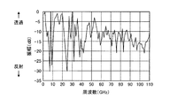
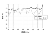
このことは図4に示すシミュレーションの結果からも明らかであり、この図4によれば、周波数0〜60GHzの電波が照射された際には電波透過性能が大きく変化している。ここで、そのシミュレーションとは、上述した単一の素子パターンからなる第1及び第2の周波数選択板12A,12Bが挿入されたFSSサンドイッチパネル10に対して0〜110GHzの範囲内で0.25GHzずつ周波数を変化させて電波を照射し、その夫々の周波数における電波透過性能を解析したものである。
This is also apparent from the simulation results shown in FIG. 4. According to FIG. 4, when radio waves having a frequency of 0 to 60 GHz are irradiated, the radio wave transmission performance changes greatly. Here, the simulation is 0.25 GHz within a range of 0 to 110 GHz with respect to the
尚、その際のFSSサンドイッチパネル10は、厚さt=25mmで複素比誘電率(1.56−j0.006)の発泡材からなるコア層11と、セル寸法が7.5mm×7.5mmの図2に示す素子パターンのセルを格子状に64×64(=4096)個配置した第1及び第2の周波数選択板12A,12Bと、厚さt=1mmで複素比誘電率(4.5−j0.036)のGFRPからなる第1及び第2の誘電体層13A,13Bとで構成されたものであり、何ら欠陥が無いものとしている。
In this case, the
一方、その図4に示すシミュレーション結果を観ると、FSSサンドイッチパネル10の設計周波数(共振周波数)よりもある程度高い周波数(60GHz以上)においては、電波照射手段21から照射させる電波の周波数を変化させても反射率と透過率は大きく変化していないことが判る。
On the other hand, the simulation result shown in FIG. 4 shows that the frequency of the radio wave emitted from the radio wave irradiation means 21 is changed at a frequency (60 GHz or higher) somewhat higher than the design frequency (resonance frequency) of the
また、電波照射手段21から照射させる電波の周波数を高くした場合には、波長が短くなり、FSSサンドイッチパネル10に対しての電波のビームが絞り易くなるので、その電波照射手段21からの電波の周波数を高くすることによって測定手段24が求めた測定結果の分解能を上げることができる。
In addition, when the frequency of the radio wave emitted from the radio wave irradiation means 21 is increased, the wavelength is shortened and the radio wave beam to the
そこで、本実施例1の非破壊検査装置20においては、FSSサンドイッチパネル10の設計周波数(共振周波数)よりも高く、且つ、そのFSSサンドイッチパネル10における反射率と透過率の変動が小さい範囲内の周波数の電波を電波照射手段21から照射させる。即ち、本実施例1の非破壊検査装置20においては、FSSサンドイッチパネル10の設計周波数(共振周波数)に対してn1倍以上の周波数の電波を電波照射手段21から照射させる。
Therefore, in the
その倍数n1は、FSSサンドイッチパネル10に設定される設計周波数(共振周波数)に応じて異なるものであり、そのFSSサンドイッチパネル10の仕様に応じてシミュレーションや実験により予め求めておく。例えば、今回のシミュレーションに用いたFSSサンドイッチパネル10の非破壊検査を行う際には、そのFSSサンドイッチパネル10に設定された共振周波数(例えば25GHz)の2.4倍(60GHz)以上の周波数で電波照射手段21から電波を照射させる。
The multiple n1 differs depending on the design frequency (resonance frequency) set in the
ここで、そのシミュレーションで用いたFSSサンドイッチパネル10を実際に試作し、そのシミュレーションと同様の条件で本実施例1の非破壊検査装置20を用いて実験した。ここでは、そのFSSサンドイッチパネル10に対して、反射率と透過率の変動が小さい75〜110GHzの範囲内で0.25GHzずつ周波数を変化させて電波照射手段21から電波を照射し、その夫々の周波数における振幅(dB)を上記のシミュレーション結果と共に観てみた。その結果を図5に示す。尚、60GHzから実験を行わなかった理由は、FSSサンドイッチパネル10を試作する際の製造誤差等を考慮してより正確な実験結果とシミュレーション結果との比較を行う為である。
Here, the
かかる実験結果によれば、75〜97GHzの範囲内においては実測値とシミュレーション結果とが略同等の周波数特性を得ていることが判る。一方、周波数が97GHzよりも高くなると、実測値の方がシミュレーション結果よりも高レベルの振幅を示していることが判る。この97GHzよりも高い周波数帯域における実測値とシミュレーション結果との相違は、かかる周波数帯域でのシミュレーションの精度,特に正確な材料定数や厚さの精度が十分でないことが原因であると考えられる。これが為、必ずしもかかる周波数帯域において電波照射手段21から電波を照射させてはならないわけではない。 According to the experimental result, it can be seen that the measured value and the simulation result have substantially the same frequency characteristics in the range of 75 to 97 GHz. On the other hand, when the frequency is higher than 97 GHz, it can be seen that the measured value shows a higher level of amplitude than the simulation result. The difference between the actually measured value and the simulation result in the frequency band higher than 97 GHz is considered to be caused by the insufficient accuracy of the simulation in the frequency band, particularly the accuracy of the accurate material constant and thickness. For this reason, the radio wave irradiation means 21 is not necessarily irradiated with radio waves in such a frequency band.
しかしながら、60〜97GHzの周波数帯域においては、特により正確な材料定数等の情報を得ることが可能であり、それ故に75〜97GHzの範囲内においては上記の結果を得られたのである。そこで、かかる実験等に用いたFSSサンドイッチパネル10の非破壊検査を行う際には、そのFSSサンドイッチパネル10に設定された共振周波数(例えば25GHz)の2.4倍以上で且つ3.9倍以下の周波数(60〜97GHz)で電波照射手段21から電波を照射させることが好ましい。尚、材料定数については、例えば、ファブリーペロー共振器法等の誘電率測定手法により取得可能である。
However, in the frequency band of 60 to 97 GHz, it is possible to obtain particularly accurate information such as material constants. Therefore, the above results are obtained in the range of 75 to 97 GHz. Therefore, when performing non-destructive inspection of the
以上のことから、本実施例1の非破壊検査装置20においては、FSSサンドイッチパネル10の設計周波数(共振周波数)に対してn1倍以上で且つn2倍以下の範囲内の周波数(60〜97GHz)の電波を電波照射手段21から照射させて非破壊検査を行うことが好ましい。
From the above, in the
ここで、その倍数n2についても、上述した倍数n1と同様にFSSサンドイッチパネル10の仕様に応じてシミュレーションや実験により予め求めておく。
Here, the multiple n2 is also obtained in advance by simulation or experiment according to the specifications of the
次に、上述したシミュレーションや実験に用いたFSSサンドイッチパネル10において欠陥を意図的に設けた供試体10Aを作成し、これを用いて本実施例1の非破壊検査装置20で非破壊検査可能か否かにつき電波の透過性能の変化を観て検証した。
Next, a
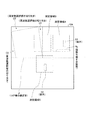
かかる検証に用いたFSSサンドイッチパネルの供試体10Aを図6に基づき説明する。この図6に示す供試体10Aにおいては、第1誘電体層13A側を表面、第2誘電体層13B側を裏面としている。
An FSS
先ず、この供試体10Aは、上述したFSSサンドイッチパネル10のコア層11を2分割し、その夫々の継ぎ目Jをコア層11のひび割れ等に相当する欠陥として設けている。また、第1周波数選択板12Aに3つの切り欠きC1〜C3を設け、これらを第1周波数選択板12Aの欠損等に相当する欠陥として設けている。また、異物に相当する欠陥としては、第1誘電体層13Aと第1周波数選択板12Aとの間及び第1周波数選択板12Aとコア層11との間に夫々鉄片S1,S2を挿入している。更に、この供試体10Aにおいては、第2誘電体層13Bの一部に樹脂を十分含浸させずに樹脂充填不足箇所RLを形成し、これを樹脂充填不足や気泡等に相当する欠陥として設けている。
First, in this
かかる検証においては、そのFSSサンドイッチパネルの供試体10Aを被検体移動手段23に取り付け、図6に示す測定領域A〜Cの3箇所について供試体10Aを1mmずつ動かして各測定点で測定を行った。また、電波照射手段21からは75〜110GHzの範囲内で0.25GHzずつ電波の周波数を変化させ、その夫々の周波数毎に測定結果を求めている。ここで、60GHzから測定を行わなかったのは上述したFSSサンドイッチパネル10の実験等を行った際と同様の理由からであり、また、110GHzまで測定を行った理由は実測値とシミュレーションとの相違による影響を観る為である。
In such verification, the
尚、その測定領域Aには第1誘電体層13Aと第1周波数選択板12Aとの間の鉄片S1及び第2誘電体層13Bの樹脂充填不足箇所RLが欠陥として設けられており、測定領域Bには第1周波数選択板12Aの切り欠きC1が欠陥として設けられている。また、測定領域Cには、コア層11の継ぎ目J及び第1周波数選択板12Aとコア層11との間の鉄片S2が欠陥として設けられている。
In addition, in the measurement area A, the iron piece S1 between the first
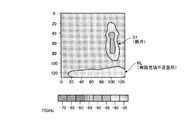
かかる検証時の各測定領域A〜Cにおける測定結果について図7から図10に示す。これら各図の測定結果は、測定手段24で算出された夫々の測定領域A〜Cにおける各測定点の電波透過性能(振幅(dB))を所定の範囲毎に色分けして表示手段(測定手段24としてのスカラネットワークアナライザ)に表示したものである。尚、図示の便宜上、これら各図においては、その色分け分布をハッチングに置き換えて図示している。また、これら各図は、複数の測定結果の中から欠陥が検知できたものを無作為に抜き出したものであり、必ずしも下記の周波数のみでしか欠陥を検知できないわけではない。 The measurement results in the measurement areas A to C at the time of such verification are shown in FIGS. The measurement results in these figures are displayed on the display means (measuring means) by color-coding the radio wave transmission performance (amplitude (dB)) of each measurement point in each measurement region A to C calculated by the measuring means 24 for each predetermined range. 24 (scalar network analyzer). For convenience of illustration, in these drawings, the color distribution is replaced with hatching. In addition, each of these figures is a random extraction of those from which a defect could be detected from among a plurality of measurement results, and it is not always possible to detect a defect only at the following frequencies.
初めに測定領域Aの測定結果について図7及び図8を用いて検証する。この測定領域Aにおいては、上述したが如く、第1誘電体層13Aと第1周波数選択板12Aとの間に鉄片S1が挿入されており、更に、裏面側の第2誘電体層13Bに樹脂充填不足箇所RLが存在している。
First, the measurement results in the measurement region A will be verified with reference to FIGS. In the measurement region A, as described above, the iron piece S1 is inserted between the first
ここで、電波照射手段21から周波数75GHzの電波を照射した際の図7の測定結果を観てみると、鉄片S1と樹脂充填不足箇所RLが存在している部位においては何ら欠陥の無い箇所よりも電波透過性能(振幅(dB))が小さくなっていることが判る。これは、鉄片S1においては電波照射手段21からの電波の殆どが反射され、樹脂充填不足箇所RLにおいてはその空洞部分の気体によって電波照射手段21からの電波が周囲よりも拡散又は反射されるからであり、これらの周囲における何ら欠陥の無い箇所よりも電波照射手段21からの電波が電波受信手段22に向けて透過し難くなっているからである。 Here, looking at the measurement result of FIG. 7 when the radio wave irradiation means 21 radiates a radio wave with a frequency of 75 GHz, in the part where the iron piece S1 and the resin filling insufficient part RL exist, the part without any defect. It can also be seen that the radio wave transmission performance (amplitude (dB)) is small. This is because most of the radio wave from the radio wave irradiation means 21 is reflected in the iron piece S1, and the radio wave from the radio wave irradiation means 21 is diffused or reflected by the gas in the hollow portion of the resin filling insufficient portion RL from the surroundings. This is because the radio waves from the radio wave irradiation means 21 are less likely to be transmitted toward the radio wave reception means 22 than the portions without any defects in the surroundings.
これと同様のことは電波照射手段21から周波数100GHzの電波を照射した際の図8の測定結果からも判る。しかしながら、かかる場合には樹脂充填不足箇所RLの存在を検知することはできるが、その樹脂充填不足箇所RLの詳細な大きさについては周波数75GHzの場合よりも明らかではない。これが為、本実施例1の非破壊検査装置20において樹脂充填不足箇所RLを探傷する際は、100GHz等のあまり高い周波数で非破壊検査を行うよりも低めの周波数を用いることが好ましい。尚、異物の探傷のみを目的とするのであれば、そのような高めの周波数で非破壊検査を行っても十分に検知することができる。
The same thing can be understood from the measurement result of FIG. 8 when the radio wave irradiation means 21 radiates a radio wave with a frequency of 100 GHz. However, in this case, the presence of the resin filling insufficient portion RL can be detected, but the detailed size of the resin filling insufficient portion RL is not clearer than the case of the frequency of 75 GHz. For this reason, when the
続いて、測定領域Bの測定結果について図9を用いて検証する。この測定領域Bにおいては、上述したが如く第1周波数選択板12Aの切り欠きC1が存在している。
Subsequently, the measurement result of the measurement region B is verified with reference to FIG. In the measurement region B, as described above, the notch C1 of the first
ここで、電波照射手段21から周波数95GHzの電波を照射した際の図9の測定結果を観てみると、切り欠きC1が存在している部位に置いては何ら欠陥の無い箇所よりも電波透過性能(振幅(dB))が小さくなっていることが判る。これは、その切り欠きC1によって第1誘電体層13Aとコア層11との間に隙間(空洞)ができ、この空洞部分の気体によって電波照射手段21からの電波が周囲よりも拡散又は反射されるからであり、これらの周囲における何ら欠陥の無い箇所よりも電波照射手段21からの電波が電波受信手段22に向けて透過し難くなっているからである。
Here, looking at the measurement result of FIG. 9 when the radio wave irradiation means 21 radiates the radio wave with the frequency of 95 GHz, the radio wave transmission is higher than the part without any defect in the part where the notch C1 exists. It can be seen that the performance (amplitude (dB)) is reduced. This is because a gap (cavity) is formed between the first
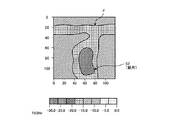
続いて、測定領域Cの測定結果について図10を用いて検証する。この測定領域Cにおいては、上述したが如く、コア層11の継ぎ目Jが存在しており、更に、第1周波数選択板12Aとコア層11との間に鉄片S2が挿入されている。
Subsequently, the measurement result in the measurement region C is verified with reference to FIG. In the measurement region C, as described above, the joint J of the
ここで、電波照射手段21から周波数75GHzの電波を照射した際の図10の測定結果を観てみると、継ぎ目Jと鉄片S2が存在している夫々においては何ら欠陥の無い箇所よりも電波透過性能(振幅(dB))が小さくなっていることが判る。これは、その継ぎ目Jにおいてはその僅かな空洞部分の気体や分割されたコア層11同士の端面によって電波照射手段21からの電波が周囲よりも拡散又は反射され、鉄片S2においては電波照射手段21からの電波の殆どが反射されるからであり、これらの周囲における何ら欠陥の無い箇所よりも電波照射手段21からの電波が電波受信手段22に向けて透過し難くなっているからである。 Here, looking at the measurement result of FIG. 10 when the radio wave irradiation means 21 radiates the radio wave with the frequency of 75 GHz, the radio wave transmission is higher than the point where there is no defect in each of the joint J and the iron piece S2. It can be seen that the performance (amplitude (dB)) is reduced. This is because the radio waves from the radio wave irradiation means 21 are diffused or reflected from the surroundings by the gas in the slight cavity portion and the end surfaces of the divided core layers 11 at the joint J, and the radio wave irradiation means 21 at the iron piece S2. This is because most of the radio waves from the radio waves are reflected, and the radio waves from the radio wave irradiation means 21 are less likely to be transmitted toward the radio wave reception means 22 than there are no defects around them.
以上示した供試体10Aによる検証結果から明らかなように、本実施例1の非破壊検査装置20においては、FSSサンドイッチパネル10の設計周波数(共振周波数)よりも高く、且つ、そのFSSサンドイッチパネル10における反射率と透過率の変動が小さい範囲内の周波数の電波を電波照射手段21から照射し、そのFSSサンドイッチパネル10における電波の透過性能を観ることによって、従来の超音波探傷,赤外線探傷又はX線探傷のみでは一度に検知し得なかったFSSサンドイッチパネル10における表面から裏面までの間の異物や樹脂充填不足箇所等の欠陥を一度に検知することができる。
As is clear from the verification results of the
特に、FSSサンドイッチパネル10の設計周波数(共振周波数)に対してn1倍以上で且つn2倍以下の範囲内の周波数(60〜97GHz)の電波を電波照射手段21から照射させることによって、より明確に欠陥を検知することができるようになるので好ましい。
In particular, the radio wave irradiation means 21 irradiates radio waves having a frequency (60 to 97 GHz) in the range of n1 times or more and n2 times or less with respect to the design frequency (resonance frequency) of the
尚、上述した本実施例1の非破壊検査装置20においては測定手段24としてスカラネットワークアナライザを用いた場合について例示したが、これに替えてベクトルネットワークアナライザを用いてもよい。かかる場合の非破壊検査装置20の一例について図11に例示する。
In the above-described
この非破壊検査装置20においては、電波照射手段21としてのアンテナと電波受信手段22としてのアンテナとが設けられており、測定手段24たるベクトルネットワークアナライザから送られ、増幅器29により増幅されたミリ波電波を電波照射手段21から放射し、電波受信手段22が検知して測定手段24たるベクトルネットワークアナライザに送る。そして、その測定手段24(ベクトルネットワークアナライザ)は、電波照射手段21(増幅器29)に送信したミリ波電波と電波受信手段22から送られてきた検知信号の夫々のレベルを比較して、FSSサンドイッチパネル10の電波透過性能(振幅(dB))の算出を行う。尚、その増幅器29は、必須の構成ではなく、測定手段24(ベクトルネットワークアナライザ)からのミリ波電波の電力の大きさ如何で必要に応じて設ければよい。
In this
また、本実施例1の非破壊検査装置20においては被検体移動手段23を用いてFSSサンドイッチパネル10を各測定点へと移動させるものについて例示しているが、そのFSSサンドイッチパネル10の位置を固定し、電波照射手段21と電波受信手段22とをFSSサンドイッチパネル10の各測定点に移動させてもよい。
Further, in the
次に、本発明に係るFSSサンドイッチパネルの非破壊検査装置及び非破壊検査方法の実施例2を図11に基づいて説明する。 Next, a second embodiment of the nondestructive inspection apparatus and nondestructive inspection method for an FSS sandwich panel according to the present invention will be described with reference to FIG.
前述した実施例1においては、電波照射手段21と電波受信手段22との間に被検体たるFSSサンドイッチパネル10を配置して、このFSSサンドイッチパネル10の電波透過性能の変化を観ることにより欠陥の有無を検知している。
In the first embodiment described above, the
しかしながら、その電波透過性能とは裏を返せば電波反射性能と一意に関連するものであり、電波の反射性能の変化を観ることによっても欠陥の有無を検知することができる。 However, the radio wave transmission performance is uniquely related to the radio wave reflection performance if reversed, and the presence or absence of defects can also be detected by observing changes in the radio wave reflection performance.
そこで、本実施例2にあっては、FSSサンドイッチパネル10の電波反射性能を検出できるように非破壊検査装置を構成し、この非破壊検査装置を用いてFSSサンドイッチパネル10の非破壊検査を行う。
Therefore, in the second embodiment, a nondestructive inspection apparatus is configured so that the radio wave reflection performance of the
図12の符号120は、本実施例2の非破壊検査装置を示す。本実施例2の非破壊検査装置120は、図11に示す如く、実施例1の非破壊検査装置20と同様の電波照射手段21,電波受信手段22,被検体移動手段23(図示略),測定手段24及び表示手段30を備えている。
ここで、本実施例2にあっては、図11に示す如く、電波照射手段21と電波受信手段22とをFSSサンドイッチパネル10に対して同一面側に配置すると共に、その電波照射手段21及び電波受信手段22をその電波照射方向及び電波受信方向がFSSサンドイッチパネル10に対して夫々逆方向の所定の角度を有するように配置する。即ち、本実施例2の電波受信手段22は、FSSサンドイッチパネル10から反射した電波照射手段21からの電波を受信できる位置に配置する。
Here, in the second embodiment, as shown in FIG. 11, the radio wave irradiation means 21 and the radio wave reception means 22 are arranged on the same surface side with respect to the
また、その電波照射手段21については、実施例1の場合と同様に、FSSサンドイッチパネル10の設計周波数(共振周波数)よりも高く、且つ、そのFSSサンドイッチパネル10における反射率と透過率の変動が小さい範囲内の周波数の電波を照射させるように構成する。
Further, the radio wave irradiation means 21 is higher than the design frequency (resonance frequency) of the
更に、本実施例2にあっては、電波照射手段21からの電波と電波受信手段22が受信した電波とからFSSサンドイッチパネル10の電波反射性能(振幅(dB))を算出し、この電波反射性能を所定の範囲毎に色分け等して表示手段30に表示させるように測定手段24を構成する。
Furthermore, in the second embodiment, the radio wave reflection performance (amplitude (dB)) of the
例えば、実施例1で例示したFSSサンドイッチパネルの供試体10Aの非破壊検査を行う場合には、その供試体10Aの設計周波数(共振周波数)に対してn1倍以上で且つn2倍以下の範囲内の周波数(60〜97GHz)の電波を電波照射手段21から照射させる。これに伴って供試体10Aから反射した電波は、電波受信手段22で受信されて測定手段24に送られる。そして、その測定手段24においては、電波照射手段21からの電波と電波受信手段22が受信した電波とから供試体10Aの電波反射性能(振幅(dB))を算出し、これを所定の範囲毎に色分け等して表示手段30に表示させる。これにより、第1周波数選択板12Aの切り欠きC1,鉄片S1,S2及びコア層11の継ぎ目Jを検知することができる。
For example, when the nondestructive inspection of the
このように非破壊検査装置120を構成して、FSSサンドイッチパネル10の設計周波数(共振周波数)よりも高く、且つ、そのFSSサンドイッチパネル10における反射率と透過率の変動が小さい範囲内の周波数の電波を電波照射手段21から照射し、そのFSSサンドイッチパネル10における電波の反射性能を観ることによっても、実施例1と同様に、従来の超音波探傷,赤外線探傷又はX線探傷のみでは一度に検知し得なかったFSSサンドイッチパネル10における表面から裏面までの間の異物や樹脂充填不足箇所等の欠陥を一度に検知することができる。
In this way, the
また、本実施例2にあっても、FSSサンドイッチパネル10の設計周波数(共振周波数)に対してn1倍以上で且つn2倍以下の範囲内の周波数(60〜97GHz)の電波を電波照射手段21から照射させることによって、より明確に欠陥を検知することができるようになるので好ましい。
Even in the second embodiment, the radio wave irradiation means 21 emits radio waves having a frequency (60 to 97 GHz) in a range not less than n1 times and not more than n2 times the design frequency (resonance frequency) of the
以上のように、本発明に係るFSSサンドイッチパネルの非破壊検査装置及び非破壊検査方法は、FSSサンドイッチパネルにおける表面から裏面までの間の異物や樹脂充填不足箇所等の欠陥を一度に検知する為の技術に適している。 As described above, the nondestructive inspection apparatus and nondestructive inspection method for an FSS sandwich panel according to the present invention are for detecting defects such as foreign matter between the front surface and the back surface of the FSS sandwich panel, and defects such as insufficient resin filling at a time. Suitable for the technology.
10 FSSサンドイッチパネル
10A FSSサンドイッチパネルの供試体
11 コア層
12A,12B 第1及び第2の周波数選択板
13A,13B 第1及び第2の誘電体層
20,120 非破壊検査装置
21 電波照射手段
22 電波受信手段
23 被検体移動手段
24 測定手段
25 信号発生器
26 電子計算機
27,28 第1及び第2の誘電体レンズ
29 増幅器
30 表示手段
J コア層の継ぎ目
RL 第2誘電体層の樹脂充填不足箇所
S1,S2 鉄片
DESCRIPTION OF
Claims (4)
前記FSSサンドイッチパネルの共振周波数よりも高く、且つ、該FSSサンドイッチパネルにおける反射率と透過率の変動が小さい範囲内の周波数の電波を当該FSSサンドイッチパネルに照射する電波照射手段と、
前記FSSサンドイッチパネルを透過した又は当該FSSサンドイッチパネルから反射した電波を受信する電波受信手段と、
前記電波照射手段から照射された電波と前記電波受信手段が受信した電波とから前記FSSサンドイッチパネルにおける電波の透過性能又は反射性能を測定する測定手段と、
を備えたことを特徴とするFSSサンドイッチパネルの非破壊検査装置。 A non-destructive inspection apparatus for an FSS sandwich panel for inspecting internal defects of an FSS sandwich panel in which a frequency selection plate for reflecting or transmitting a radio wave of a specific frequency is inserted,
Radio wave irradiation means for irradiating the FSS sandwich panel with radio waves having a frequency that is higher than the resonance frequency of the FSS sandwich panel and within a range in which fluctuations in reflectance and transmittance in the FSS sandwich panel are small;
Radio wave receiving means for receiving radio waves transmitted through the FSS sandwich panel or reflected from the FSS sandwich panel;
Measurement means for measuring radio wave transmission performance or reflection performance in the FSS sandwich panel from radio waves emitted from the radio wave irradiation means and radio waves received by the radio wave reception means;
A non-destructive inspection apparatus for FSS sandwich panels, comprising:
前記FSSサンドイッチパネルの共振周波数よりも高く、且つ、該FSSサンドイッチパネルにおける反射率と透過率の変動が小さい範囲内の周波数の電波を当該FSSサンドイッチパネルに照射する工程と、
前記FSSサンドイッチパネルを透過した又は当該FSSサンドイッチパネルから反射した電波を受信する工程と、
前記FSSサンドイッチパネルに照射された電波と当該FSSサンドイッチパネルからの透過電波又は反射電波とから当該FSSサンドイッチパネルにおける電波の透過性能又は反射性能を測定する工程と、
を有することを特徴としたFSSサンドイッチパネルの非破壊検査方法。 A non-destructive inspection method for an FSS sandwich panel for inspecting an internal defect of an FSS sandwich panel in which a frequency selection plate for reflecting or transmitting a radio wave of a specific frequency is inserted,
Irradiating the FSS sandwich panel with radio waves having a frequency that is higher than the resonance frequency of the FSS sandwich panel and within a range in which fluctuations in reflectance and transmittance in the FSS sandwich panel are small;
Receiving radio waves transmitted through the FSS sandwich panel or reflected from the FSS sandwich panel;
Measuring the transmission performance or reflection performance of radio waves in the FSS sandwich panel from radio waves irradiated on the FSS sandwich panel and radio waves transmitted or reflected from the FSS sandwich panel;
A non-destructive inspection method for an FSS sandwich panel, comprising:
Priority Applications (1)
| Application Number | Priority Date | Filing Date | Title |
|---|---|---|---|
| JP2005199180A JP2007017289A (en) | 2005-07-07 | 2005-07-07 | Non-destructive inspection system and non-destructive inspection method of fss sandwich panel |
Applications Claiming Priority (1)
| Application Number | Priority Date | Filing Date | Title |
|---|---|---|---|
| JP2005199180A JP2007017289A (en) | 2005-07-07 | 2005-07-07 | Non-destructive inspection system and non-destructive inspection method of fss sandwich panel |
Publications (1)
| Publication Number | Publication Date |
|---|---|
| JP2007017289A true JP2007017289A (en) | 2007-01-25 |
Family
ID=37754578
Family Applications (1)
| Application Number | Title | Priority Date | Filing Date |
|---|---|---|---|
| JP2005199180A Pending JP2007017289A (en) | 2005-07-07 | 2005-07-07 | Non-destructive inspection system and non-destructive inspection method of fss sandwich panel |
Country Status (1)
| Country | Link |
|---|---|
| JP (1) | JP2007017289A (en) |
Cited By (5)
| Publication number | Priority date | Publication date | Assignee | Title |
|---|---|---|---|---|
| CN105203562A (en) * | 2015-08-31 | 2015-12-30 | 中国舰船研究设计中心 | Testing system for insertion phase delay of frequency selection material and testing method thereof |
| US10048369B2 (en) | 2015-02-09 | 2018-08-14 | Denso Corporation | Radar assembly |
| JP2021025847A (en) * | 2019-08-02 | 2021-02-22 | 国立大学法人京都大学 | Foreign matter inspection device |
| JP7106183B1 (en) * | 2021-03-17 | 2022-07-26 | 株式会社辰巳菱機 | inspection system |
| WO2022196317A1 (en) * | 2021-03-17 | 2022-09-22 | 株式会社辰巳菱機 | Inspection system |
-
2005
- 2005-07-07 JP JP2005199180A patent/JP2007017289A/en active Pending
Cited By (6)
| Publication number | Priority date | Publication date | Assignee | Title |
|---|---|---|---|---|
| US10048369B2 (en) | 2015-02-09 | 2018-08-14 | Denso Corporation | Radar assembly |
| CN105203562A (en) * | 2015-08-31 | 2015-12-30 | 中国舰船研究设计中心 | Testing system for insertion phase delay of frequency selection material and testing method thereof |
| JP2021025847A (en) * | 2019-08-02 | 2021-02-22 | 国立大学法人京都大学 | Foreign matter inspection device |
| JP7287625B2 (en) | 2019-08-02 | 2023-06-06 | 国立大学法人京都大学 | Contaminant inspection device |
| JP7106183B1 (en) * | 2021-03-17 | 2022-07-26 | 株式会社辰巳菱機 | inspection system |
| WO2022196317A1 (en) * | 2021-03-17 | 2022-09-22 | 株式会社辰巳菱機 | Inspection system |
Similar Documents
| Publication | Publication Date | Title |
|---|---|---|
| Foudazi et al. | Active microwave thermography for defect detection of CFRP-strengthened cement-based materials | |
| EP1444496B1 (en) | Method and apparatus for generating specific frequency response for ultrasound testing | |
| Ospald et al. | Aeronautics composite material inspection with a terahertz time-domain spectroscopy system | |
| Ibrahim | Nondestructive testing and structural health monitoring of marine composite structures | |
| Yu et al. | Remote defect detection of FRP-bonded concrete system using acoustic-laser and imaging radar techniques | |
| Mukherjee et al. | Far field microwave NDE of composite structures using time reversal mirror | |
| Park et al. | Non-destructive evaluation of the hidden voids in integrated circuit packages using terahertz time-domain spectroscopy | |
| US9726618B2 (en) | Sensing system and method | |
| US8176785B2 (en) | Method and device for detecting water in a cellular structure | |
| Zhong et al. | Remote inspection system for impact damage in large composite structure | |
| Barazanchy et al. | A hybrid structural health monitoring system for the detection and localization of damage in composite structures | |
| US11860131B2 (en) | System and method for portable ultrasonic testing | |
| Zhang et al. | Broadband stepped-frequency modulated continuous terahertz wave tomography for non-destructive inspection of polymer materials | |
| JP4528833B2 (en) | System for detecting, quantifying and / or locating water in an aircraft sandwich structure and method of implementing this system | |
| An et al. | Defect visualization of cylindrical and conical CFRP lattice structures using rotational ultrasonic propagation imager | |
| Abu-Khousa et al. | Defect imaging and characterization in composite structures using near-field microwave nondestructive testing techniques | |
| JP2007017289A (en) | Non-destructive inspection system and non-destructive inspection method of fss sandwich panel | |
| CN115856076B (en) | CFRP plate small-size defect measurement method, device and system based on air-coupled ultrasound | |
| Vaara et al. | Technology survey on NDT of carbon-fiber composites | |
| Ravuri et al. | Microwave and millimeter wave near‐field methods for evaluation of radome composites | |
| Tian et al. | Frequency domain time reversal adaptive focusing on nondestructive testing imaging method for composite materials | |
| Mirala et al. | Nondestructive assessment of microwave absorbing structures via active microwave thermography | |
| Kharkovsky et al. | Millimeter wave detection of localized anomalies in the space shuttle external fuel tank insulating foam and acreage heat tiles | |
| Wanga et al. | Air-coupled ultrasonic detection of microholes in flexible envelope materials | |
| Xu et al. | A method for rapid locating internal defects of composite structure based on laser ultrasonic |