JP2007016643A - Hermetic compressor - Google Patents

Hermetic compressor Download PDF

Info

Publication number
JP2007016643A
JP2007016643A JP2005197176A JP2005197176A JP2007016643A JP 2007016643 A JP2007016643 A JP 2007016643A JP 2005197176 A JP2005197176 A JP 2005197176A JP 2005197176 A JP2005197176 A JP 2005197176A JP 2007016643 A JP2007016643 A JP 2007016643A
Authority
JP
Japan
Prior art keywords
oil
capillary
bearing
hermetic compressor
block
Prior art date
Legal status (The legal status is an assumption and is not a legal conclusion. Google has not performed a legal analysis and makes no representation as to the accuracy of the status listed.)
Pending
Application number
JP2005197176A
Other languages
Japanese (ja)
Inventor
Hidenori Kobayashi
秀則 小林
Hidetoshi Nishihara
秀俊 西原
Current Assignee (The listed assignees may be inaccurate. Google has not performed a legal analysis and makes no representation or warranty as to the accuracy of the list.)
Panasonic Holdings Corp
Original Assignee
Matsushita Electric Industrial Co Ltd
Priority date (The priority date is an assumption and is not a legal conclusion. Google has not performed a legal analysis and makes no representation as to the accuracy of the date listed.)
Filing date
Publication date
Application filed by Matsushita Electric Industrial Co Ltd filed Critical Matsushita Electric Industrial Co Ltd
Priority to JP2005197176A priority Critical patent/JP2007016643A/en
Publication of JP2007016643A publication Critical patent/JP2007016643A/en
Pending legal-status Critical Current

Links

Images

Abstract

<P>PROBLEM TO BE SOLVED: To provide a compressor increased in reliability by preventing its reliability from lowering due to defective lubrication to the sliding portions of the compression elements of the compressor. <P>SOLUTION: A plurality of oil reservoirs 130, 136 into which an oil 113 flows sequentially are formed in the compression elements 112, and an oil capillary 155 is formed in each of the oil reservoirs 130. Since metal particles contained in the oil flowing into the oil reservoirs 130 positioned on the downstream side are reduced, the oil capillary 155 is prevented from being clogged with metal particles. <P>COPYRIGHT: (C)2007,JPO&INPIT

Description

本発明は密閉型圧縮機(以下圧縮機という)の信頼性の向上に関するものである。   The present invention relates to an improvement in the reliability of a hermetic compressor (hereinafter referred to as a compressor).

従来、この種の圧縮機は圧縮室を有するブロックの上面部に設けられたオイル溜め槽に、一端がオイル溜め槽に開口し、他端が圧縮室に連通するマフラー内に開口するオイルキャピラリーを備えたものがある(例えば、特許文献1参照)。   Conventionally, this type of compressor has an oil reservoir provided on an upper surface of a block having a compression chamber, and an oil capillary having one end opened in the oil reservoir and the other end opened in a muffler communicating with the compression chamber. Some are provided (see, for example, Patent Document 1).

以下、図面を参照しながら上記従来の圧縮機を説明する。   The conventional compressor will be described below with reference to the drawings.

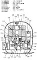
図4は、特許文献1に記載された従来の圧縮機を示す断面図、図5は、特許文献1に記載された従来の圧縮機を示す要部拡大図である。   4 is a cross-sectional view showing a conventional compressor described in Patent Document 1, and FIG. 5 is an enlarged view of a main part showing the conventional compressor described in Patent Document 1. As shown in FIG.

図4、図5において、密閉容器1は、鉄板の絞り成型によって形成された上容器2と下容器3から形成されている。密閉容器1は、巻き線5を保有する固定子6と回転子8からなる電動要素10と、電動要素10によって駆動される圧縮要素12を収容し、底部にオイル13を貯留している。   4 and 5, the sealed container 1 is formed of an upper container 2 and a lower container 3 formed by drawing a steel plate. The sealed container 1 accommodates an electric element 10 including a stator 6 and a rotor 8 holding a winding 5 and a compression element 12 driven by the electric element 10, and stores oil 13 at the bottom.

次に圧縮要素12について説明する。   Next, the compression element 12 will be described.

シャフト16は、回転子8を圧入固定した主軸部18および主軸部18に対して偏心して形成された偏心部20を有し、偏心部20の先端にオイルポンプ22が圧入固定され、偏心部20から主軸部18に渡って給油経路23を備えている。   The shaft 16 has a main shaft portion 18 into which the rotor 8 is press-fitted and fixed, and an eccentric portion 20 formed eccentrically with respect to the main shaft portion 18, and an oil pump 22 is press-fitted and fixed to the tip of the eccentric portion 20. An oil supply path 23 is provided from the main shaft 18 to the main shaft 18.

ブロック26は、略円筒形の圧縮室28を形成し、主軸部18を軸支するベアリング31を備えている。   The block 26 forms a substantially cylindrical compression chamber 28 and includes a bearing 31 that supports the main shaft portion 18.

ピストン39は、圧縮室28に往復摺動自在に挿入され、偏心部20との間を連結手段40によって連結されている。   The piston 39 is inserted into the compression chamber 28 so as to be slidable back and forth, and is connected to the eccentric portion 20 by a connecting means 40.

圧縮室28の開口端面を封止するバルブプレート41は吸入バルブ42の開閉により圧縮室28と連通する吸入孔43を備えている。   The valve plate 41 that seals the open end face of the compression chamber 28 includes a suction hole 43 that communicates with the compression chamber 28 by opening and closing the suction valve 42.

高圧室を形成するシリンダーヘッド44は、バルブプレート41を介して圧縮室28の反対側に、吸入孔43に連通するマフラー46と共に固定されている。   The cylinder head 44 forming the high pressure chamber is fixed to the opposite side of the compression chamber 28 via the valve plate 41 together with the muffler 46 communicating with the suction hole 43.

ブロック26は、圧縮室28上面にオイル溜め槽30を有している。   The block 26 has an oil reservoir 30 on the upper surface of the compression chamber 28.

オイルキャピラリー55は、一端がオイル溜め槽30に開口し、他端がマフラー46内に開口している。   One end of the oil capillary 55 opens into the oil reservoir 30 and the other end opens into the muffler 46.

以上のように構成された圧縮機について、以下その動作を説明する。   The operation of the compressor configured as described above will be described below.

電動要素10に電気が供給されることで回転子8とともにシャフト16が回転し、偏芯部20の偏芯運動が連結手段40を介してピストン39に伝わることでピストン39は圧縮室28で往復運動を行い、連続して冷媒を圧縮する。   By supplying electricity to the electric element 10, the shaft 16 rotates together with the rotor 8, and the eccentric movement of the eccentric portion 20 is transmitted to the piston 39 via the connecting means 40, so that the piston 39 reciprocates in the compression chamber 28. It moves and continuously compresses the refrigerant.

オイルポンプ22下端から給油経路23へ遠心力により引き上げられたオイル13は、主軸部18を潤滑した後、ベアリング31の上端部から流出してベアリング31外周面を伝わり流れ、一部はオイル溜め槽30に連続的に流入する。オイル溜め槽30に溜まったオイル13はマフラー46内と密閉容器1内との差圧によってオイルキャピラリー55を介してマフラー46内に給油され、マフラー46内を流れる冷媒ガス(図示せず)とともに、霧状のオイル13となって吸入孔43から圧縮室28に吸入される。   The oil 13 pulled up by the centrifugal force from the lower end of the oil pump 22 to the oil supply path 23 lubricates the main shaft portion 18 and then flows out from the upper end portion of the bearing 31 and flows along the outer peripheral surface of the bearing 31, and a part of the oil reservoir tank. 30 continuously flows. The oil 13 accumulated in the oil reservoir 30 is supplied into the muffler 46 through the oil capillary 55 due to the differential pressure between the muffler 46 and the sealed container 1, and together with a refrigerant gas (not shown) flowing through the muffler 46, It becomes mist-like oil 13 and is sucked into the compression chamber 28 from the suction hole 43.

オイルキャピラリー55はほぼ同じ高さに位置するオイル溜め槽30からオイルを吸引するので揚程が低く、小さな差圧でも確実にマフラー46内に給油される。   The oil capillary 55 sucks oil from the oil reservoir 30 located at almost the same height, so that the lift is low, and the oil is reliably supplied into the muffler 46 even with a small differential pressure.

その結果、吸入孔43と吸入バルブ42間、ピストン39と圧縮室28間とのオイル潤滑が良好になり、信頼性を向上させることができる。
特開2002−130129号公報
As a result, the oil lubrication between the suction hole 43 and the suction valve 42 and between the piston 39 and the compression chamber 28 becomes good, and the reliability can be improved.
JP 2002-130129 A

しかしながら、上記従来の構成では、圧縮機の運転にともなってオイルポンプ22から密閉容器1内に微量に残っている金属紛や、各摺動部より発生した金属紛がオイル13中に混入しオイル溜め槽30に注入するため、金属紛が主にオイル溜め部30の底部付近に滞留する。滞留した金属紛はオイルキャピラリー55先端部からオイル13とともに吸入されるため、オイルキャピラリー55内に金属紛が詰まり、マフラー46内にオイル13が給油されず、各摺動部へのオイル潤滑の不良になり信頼性の低下という課題を有していた。   However, in the above-described conventional configuration, a small amount of metal powder remaining in the sealed container 1 from the oil pump 22 or metal powder generated from each sliding portion is mixed in the oil 13 as the compressor is operated, and the oil 13 In order to inject into the reservoir 30, the metal powder stays mainly near the bottom of the oil reservoir 30. Since the accumulated metal powder is sucked together with the oil 13 from the tip of the oil capillary 55, the metal powder is clogged in the oil capillary 55, the oil 13 is not supplied into the muffler 46, and the oil lubrication to each sliding portion is poor. Therefore, there was a problem of lowering reliability.

本発明は、上記従来の課題を解決するもので、オイルキャピラリー55から安定した給油を行い、信頼性を向上させた圧縮機を提供することを目的とする。   The present invention solves the above-described conventional problems, and an object of the present invention is to provide a compressor that stably supplies oil from the oil capillary 55 and has improved reliability.

上記従来の課題を解決するために、本発明の圧縮機は、オイルが順次流れ込む複数のオイル溜め槽を圧縮要素に形成し、オイル溜め槽のうち下流側に位置するオイル溜め槽に一端が開口し、他端が前記マフラー内に開口するオイルキャピラリーを設けたもので,オイル溜め槽を複数設けることにより、オイル中に含まれる金属紛が上流側のオイル溜めに順次沈殿するため、下流側に位置するオイル溜め槽へ流入する金属紛が減小するので、オイルキャピラリーから吸引される金属紛の量が減り、オイルキャピラリーの詰まりを防ぐという作用を有する。   In order to solve the above-described conventional problems, the compressor of the present invention has a plurality of oil sump tanks into which oil flows sequentially in a compression element, and one end is open to an oil sump tank located downstream of the oil sump tanks. The other end is provided with an oil capillary that opens into the muffler. By providing a plurality of oil sump tanks, the metal powder contained in the oil sequentially settles in the oil sump on the upstream side. Since the metal powder flowing into the oil reservoir located is reduced, the amount of metal powder sucked from the oil capillary is reduced, and the oil capillary is prevented from being clogged.

本発明の圧縮機は、オイルキャピラリーの詰まりを防ぐことができるので、信頼性を向上させることができる。   Since the compressor of the present invention can prevent clogging of the oil capillary, the reliability can be improved.

請求項1に記載の発明は、圧縮要素と、前記圧縮要素を駆動するとともに前記圧縮要素の上方に配設された電動要素と、冷媒ガスとオイルを封入するとともに前記圧縮要素および前記電動要素を収容する密閉容器を備え、前記圧縮要素は圧縮室を有するブロックと、略鉛直方向に配設され下端にオイルポンプを備えたシャフトと、前記ブロックの上面に配設され前記シャフトを軸支するベアリングと、前記圧縮室に連通するマフラーを有し、一端が前記オイルポンプに連通し、他端が前記ベアリングの上端面に連通する給油経路を前記シャフトに設けるとともに、前記給油経路から流出したオイルが順次流れ込む複数のオイル溜め槽を前記圧縮要素に形成し、前記オイル溜め槽のうち下流側に位置するオイル溜め槽に一端が開口し、他端が前記マフラー内に開口するオイルキャピラリーを設けたもので、オイル溜め槽を複数設けることにより、オイル中に含まれる金属紛が上流側のオイル溜めに順次沈殿するため、下流側に位置するオイル溜め槽へ流入するオイル中に含まれる金属紛を減小させることができ、オイルキャピラリーから吸引される金属紛の量が減り、オイルキャピラリーの詰まりを防ぐことで安定した給油が得られ、信頼性を向上させることができる。   The invention according to claim 1 includes a compression element, an electric element that drives the compression element and is disposed above the compression element, encloses refrigerant gas and oil, and includes the compression element and the electric element. An airtight container for housing, the compression element having a block having a compression chamber; a shaft disposed in a substantially vertical direction and having an oil pump at a lower end; and a bearing disposed on an upper surface of the block and pivotally supporting the shaft. And a muffler that communicates with the compression chamber, one end of which communicates with the oil pump, and the other end of which communicates with the upper end surface of the bearing. A plurality of oil sump tanks that flow sequentially are formed in the compression element, one end of the oil sump tank is opened to the downstream side, and the other end is the front side. An oil capillary that opens in the muffler is provided. By providing multiple oil reservoirs, the metal powder contained in the oil is deposited in the oil reservoir on the upstream side in sequence. The metal powder contained in the flowing oil can be reduced, the amount of metal powder sucked from the oil capillary is reduced, and the oil capillary is prevented from clogging, so that stable oil supply is obtained and the reliability is improved. be able to.

請求項2に記載の発明は、請求項1に記載の発明においてベアリングのブロック近傍に全周に渡って環状の溝を設け、これを上流側に位置するオイル溜め槽としたもので、ベアリング上端から流出するほとんどのオイルがベアリングに設けたオイル溜め槽を通過するので、より確実にオイル中に含まれる金属紛をベアリングに設けたオイル溜め槽で沈殿させることができ、オイル中の金属紛の量が減り、さらに信頼性を向上させることが出来る。   The invention according to claim 2 is the invention according to claim 1, wherein an annular groove is provided around the entire circumference of the bearing block, and this is used as an oil sump tank located on the upstream side. Most of the oil that flows out of the oil passes through the oil reservoir provided in the bearing, so that the metal powder contained in the oil can be more reliably precipitated in the oil reservoir provided in the bearing. The amount is reduced and the reliability can be further improved.

請求項3に記載の発明は、請求項1に記載の発明においてオイル溜め槽に貯留されたオイル中に開口するオイルキャピラリーの開口部を上向けに形成したもので、オイル溜め槽底部に金属紛が滞留してもオイルキャピラリーの開口部が上向きに形成されているので、金属紛の少ない上層のオイルがオイルキャピラリーから吸引されるため、さらに信頼性を向上させることができる。   The invention according to claim 3 is the one in which the opening of the oil capillary that opens into the oil stored in the oil reservoir is formed upward in the invention of claim 1, and the metal powder is formed at the bottom of the oil reservoir. Even if the oil stays, the opening of the oil capillary is formed upward, so that the upper oil with less metal powder is sucked from the oil capillary, so that the reliability can be further improved.

請求項4に記載の発明は、請求項1に記載の発明において少なくともひとつのオイル溜め槽内に永久磁石からなるトラップを配置したもので、オイル溜め槽に流れ込むオイルに含まれる金属紛の内の鉄粉を永久磁石によって吸着できるため、さらにオイルキャピラリーから吸引される金属紛の量が減り、信頼性を向上させることができる。   According to a fourth aspect of the present invention, in the first aspect of the invention, at least one oil reservoir tank is provided with a trap made of a permanent magnet. Of the metal powder contained in the oil flowing into the oil reservoir tank, Since iron powder can be adsorbed by a permanent magnet, the amount of metal powder sucked from the oil capillary is further reduced, and the reliability can be improved.

請求項5に記載の発明は、請求項2または4に記載の発明においてベアリングは複数のボルトでブロックに螺着され、少なくともひとつのボルトをオイル溜め槽内に配設するとともに、前記ボルトを永久磁石としたもので、圧縮機を構成する部品点数を増やすことなく、オイル溜め槽内に流れ込むオイルに含まれる金属紛の内の鉄粉を吸着できるので、さらにコストを抑える事が出来る。   The invention according to claim 5 is the invention according to claim 2 or 4, wherein the bearing is screwed to the block with a plurality of bolts, and at least one bolt is disposed in the oil sump tank, and the bolt is permanently attached. Since it is a magnet, the iron powder in the metal powder contained in the oil flowing into the oil reservoir can be adsorbed without increasing the number of parts constituting the compressor, so that the cost can be further reduced.

以下、本発明の実施の形態について、図面を参照しながら説明する。なお、この実施の形態によってこの発明が限定されるものではない。   Hereinafter, embodiments of the present invention will be described with reference to the drawings. The present invention is not limited to the embodiments.

(実施の形態1)
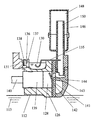
図1は、本発明の実施の形態1における圧縮機の断面図、図2は、同実施の形態における圧縮機の要部斜視図、図3は、同実施の形態における圧縮機の要部拡大図である。
(Embodiment 1)
1 is a cross-sectional view of a compressor according to Embodiment 1 of the present invention, FIG. 2 is a perspective view of a main part of the compressor according to the same embodiment, and FIG. 3 is an enlarged view of a main part of the compressor according to the same embodiment. FIG.

図1、図2、図3において、密閉容器101は、鉄板の絞り成型によって形成された上容器102と下容器103から形成されている。   1, 2, and 3, the sealed container 101 is formed of an upper container 102 and a lower container 103 formed by drawing a steel plate.

密閉容器101は、巻き線105を保有する固定子106と回転子108からなる電動要素110と、電動要素110によって駆動される圧縮要素112を収容し、オイル113が密閉容器101底部に貯溜されている。   The sealed container 101 houses an electric element 110 including a stator 106 and a rotor 108 that have a winding 105, and a compression element 112 that is driven by the electric element 110, and oil 113 is stored at the bottom of the sealed container 101. Yes.

次に圧縮要素112について説明する。   Next, the compression element 112 will be described.

シャフト116は、回転子108を圧入固定した主軸部118および主軸部118に対して偏心して形成された偏心部120を有し、偏心部120の先端にオイルポンプ122が圧入固定されている。   The shaft 116 has a main shaft portion 118 on which the rotor 108 is press-fitted and fixed, and an eccentric portion 120 formed eccentrically with respect to the main shaft portion 118, and an oil pump 122 is press-fitted and fixed to the tip of the eccentric portion 120.

オイルポンプ122が圧入固定されている偏心部120の先端部から主軸部118下端まで鉛直上方に中空の孔124が設けられ、主軸部118下端から主軸部118上端まではシャフト116表面に沿ってらせん状にオイル溝125が形成されている。オイル溝125は主軸部下端で中空の孔124と連通することで給油経路123は形成されている。   A hollow hole 124 is provided vertically upward from the tip of the eccentric part 120 to which the oil pump 122 is press-fitted and fixed to the lower end of the main shaft part 118, and from the lower end of the main shaft part 118 to the upper end of the main shaft part 118, spiral along the surface of the shaft 116. An oil groove 125 is formed in a shape. The oil groove 125 communicates with the hollow hole 124 at the lower end of the main shaft portion, so that an oil supply path 123 is formed.

ブロック126は、略円筒形の圧縮室128を形成し、主軸部118を軸支するベアリング131を備えている。また圧縮室128上面にはオイル溜め槽130を凹設している。   The block 126 forms a substantially cylindrical compression chamber 128 and includes a bearing 131 that supports the main shaft portion 118. An oil reservoir tank 130 is recessed on the upper surface of the compression chamber 128.

ピストン139は、圧縮室128に往復摺動自在に挿入され、偏心部120との間を連結手段140によって連結されている。   The piston 139 is inserted into the compression chamber 128 so as to be slidable back and forth, and is connected to the eccentric portion 120 by a connecting means 140.

圧縮室128の開口端面を封止するバルブプレート141は吸入バルブ142の開閉により圧縮室128と連通する吸入孔143を備えている。   The valve plate 141 that seals the opening end surface of the compression chamber 128 includes a suction hole 143 that communicates with the compression chamber 128 by opening and closing the suction valve 142.

高圧室を形成するシリンダーヘッド144は、バルブプレート141を介して圧縮室128の反対側に固定されている。   A cylinder head 144 forming a high pressure chamber is fixed to the opposite side of the compression chamber 128 via a valve plate 141.

合成樹脂で形成されているマフラー146は消音空間148を形成するとともに、一端が吸入孔143に連通し、他端が消音空間148に連通する連通管150と、消音空間148と連通する吸入口152を備えており、バルブプレート141とシリンダーヘッド144の間に挟持固定されている。   The muffler 146 formed of a synthetic resin forms a silencing space 148, a communication pipe 150 having one end communicating with the suction hole 143 and the other end communicating with the silencing space 148, and a suction port 152 communicating with the silencing space 148. And is fixed between the valve plate 141 and the cylinder head 144.

ベアリング131はアルミダイキャストや鋳物等の摺動性の良い材料で形成され、ブロック126に螺着固定するための複数のボルト孔132を穿設したフランジ部133と、シャフトの主軸部を軸支する軸受部134からなる。そして軸受部134の上端面には給油経路123の上端からのオイル113が流出する切欠き135が形成されている。   The bearing 131 is formed of a material having good slidability such as aluminum die-casting or casting, and a flange portion 133 having a plurality of bolt holes 132 for screwing and fixing to the block 126, and a main shaft portion of the shaft are supported. It consists of a bearing part 134. A notch 135 through which oil 113 flows from the upper end of the oil supply path 123 is formed on the upper end surface of the bearing portion 134.

ベアリング131のブロック126近傍に位置するフランジ部133には、全周に渡って環状の溝からなる上流オイル溜め槽136が複数のボルト孔132にさしかかるように形成されている。フランジ部133の外周近傍には、上流オイル溜め槽136と連通するオイル通路137をオイル溜め槽130側に設けている。   An upstream oil sump tank 136 formed of an annular groove is formed on the flange portion 133 located in the vicinity of the block 126 of the bearing 131 so as to reach the plurality of bolt holes 132. In the vicinity of the outer periphery of the flange portion 133, an oil passage 137 communicating with the upstream oil reservoir tank 136 is provided on the oil reservoir tank 130 side.

そしてベアリング131は永久磁石からなるボルト138によってブロック126に螺着されている。   The bearing 131 is screwed to the block 126 by a bolt 138 made of a permanent magnet.

オイルキャピラリー155は、一端がオイル溜め槽130に開口し、他端がマフラー146内に開口するように配置され、マフラー146に固定されている。   The oil capillary 155 is arranged so that one end opens into the oil reservoir tank 130 and the other end opens into the muffler 146, and is fixed to the muffler 146.

オイル溜め漕130に開口するオイルキャピラリー155の開口部は重力方向に対し上向きに形成されている。   The opening of the oil capillary 155 that opens to the oil reservoir 130 is formed upward with respect to the direction of gravity.

以上のように構成された圧縮機について、以下その動作、作用を説明する。   About the compressor comprised as mentioned above, the operation | movement and an effect | action are demonstrated below.

電動要素110に電気が供給されることでシャフト116が回転し、偏芯部120の回転運動で連結手段140を介してピストン139が圧縮室128で往復運動を行う。   When electricity is supplied to the electric element 110, the shaft 116 rotates, and the piston 139 reciprocates in the compression chamber 128 via the connecting means 140 by the rotational movement of the eccentric part 120.

下容器103の底部のオイル113は、オイルポンプ122下端から偏心部120内の中空の孔124を通り主軸部118下端まで遠心力により引き上げられる。主軸部118下端でシャフト116表面に出たオイル113は、シャフト116の回転により主軸部118下端から上端まではオイル溝125に沿ってオイル113は上昇し、主軸部118を潤滑する。   The oil 113 at the bottom of the lower container 103 is pulled up by centrifugal force from the lower end of the oil pump 122 through the hollow hole 124 in the eccentric part 120 to the lower end of the main shaft part 118. The oil 113 that has come out on the surface of the shaft 116 at the lower end of the main shaft portion 118 rises along the oil groove 125 from the lower end to the upper end of the main shaft portion 118 due to the rotation of the shaft 116, and lubricates the main shaft portion 118.

主軸部118上端まで上昇したオイル113はベアリング131の切欠き135から流出して軸受部134の外周面を伝わり流れ、フランジ部133に全周に渡って設けられた環状の溝からなる上流オイル溜め槽136に溜まる。上流オイル溜め槽136はフランジ部133に全周に渡って設けられているため、切欠き135から流出したほとんどのオイル113は一旦この上流オイル溜め槽136に流入する。   The oil 113 rising to the upper end of the main shaft portion 118 flows out of the notch 135 of the bearing 131 and flows along the outer peripheral surface of the bearing portion 134, and is an upstream oil sump consisting of an annular groove provided in the flange portion 133 over the entire circumference. It accumulates in the tank 136. Since the upstream oil reservoir tank 136 is provided on the flange 133 over the entire circumference, most of the oil 113 that has flowed out of the notch 135 once flows into the upstream oil reservoir tank 136.

上流オイル溜め槽136に流入したオイル113に含まれる金属粉はここで上流オイル溜め槽136底部に沈殿するとともに、金属紛に含まれる鉄粉は上流オイル溜め槽136に位置する永久磁石からなるボルト138によって吸着されるので、極めて金属紛の含有量の少ないオイル113がオイル通路137を通って、ブロック126に設けたオイル溜め槽130に流入する。   The metal powder contained in the oil 113 flowing into the upstream oil sump tank 136 settles here at the bottom of the upstream oil sump tank 136, and the iron powder contained in the metal powder is a bolt made of a permanent magnet located in the upstream oil sump tank 136. Therefore, the oil 113 having a very small amount of metal powder flows through the oil passage 137 and flows into the oil reservoir 130 provided in the block 126.

そしてオイル113に僅かに含有された金属紛はさらにこの下流に位置するオイル溜め槽130の中で底部に沈殿する。   The metal powder slightly contained in the oil 113 is further precipitated at the bottom in the oil reservoir tank 130 located downstream of this.

オイル溜め槽130のオイル113は、マフラー146内の管摩擦による圧力損失と、流れによる動圧降下によって生じるマフラー146内と密閉容器101内との差圧により開口部が上向きに形成されたオイルキャピラリー155を介してマフラー146内に給油され、マフラー146を流れる冷媒(図示せず)とともにガス霧状のオイル113となって、吸入バルブ142の開閉により吸入孔143から圧縮室128に吸入される。   The oil 113 in the oil sump tank 130 is an oil capillary whose opening is formed upward due to a pressure loss due to pipe friction in the muffler 146 and a pressure difference between the muffler 146 and the sealed container 101 caused by a dynamic pressure drop due to the flow. The oil is supplied into the muffler 146 through 155, and becomes a gas-mist-like oil 113 together with a refrigerant (not shown) flowing through the muffler 146, and is sucked into the compression chamber 128 from the suction hole 143 by opening and closing of the suction valve 142.

オイルキャピラリー155はほぼ同じ高さに位置するオイル溜め槽130からオイルを吸引するので揚程が低く、小さな差圧でも確実にマフラー146内に給油される。   The oil capillary 155 sucks oil from the oil reservoir 130 located at almost the same height, so that the lift is low, and the oil is reliably supplied into the muffler 146 even with a small differential pressure.

ここでオイル溜め漕130に開口するオイルキャピラリー155の開口部は重力方向に対し上向きに形成されているので、底部に沈殿した金属紛を吸引力で巻き上げて吸引することが防げ、オイルキャピラリー155からはほとんど金属紛を含まないオイル113がマフラー146内に給油されることになる。   Here, since the opening of the oil capillary 155 that opens to the oil reservoir 130 is formed upward with respect to the direction of gravity, the metal powder precipitated on the bottom can be prevented from being wound up by suction and sucked from the oil capillary 155. The oil 113 containing almost no metal powder is supplied into the muffler 146.

その結果、金属粉等の流入によるオイルキャピラリー155の詰まりを防ぎ、安定した給油によって、吸入孔143と吸入バルブ142及びバルブプレート141とのシール性を良好にし、ピストン139と圧縮室128との潤滑、摺動を良好にして、効率、信頼性を向上させ、更に各部品が衝突する際に発生する騒音を低減することができる。   As a result, clogging of the oil capillary 155 due to inflow of metal powder or the like is prevented, stable oil supply improves the sealing performance between the suction hole 143, the suction valve 142, and the valve plate 141, and the piston 139 and the compression chamber 128 are lubricated. The sliding can be improved, the efficiency and reliability can be improved, and the noise generated when the parts collide can be reduced.

なお、本実施の形態においては圧縮室128上面にオイル溜め槽130をひとつ設けたものを例示したが、これが複数あってもよい。   In the present embodiment, an example in which one oil reservoir 130 is provided on the upper surface of the compression chamber 128 is illustrated, but a plurality of oil reservoirs 130 may be provided.

また、本実施の形態において、ボルト138を永久磁石にしたが、別途形成した永久磁石がオイル溜め漕内に配置されてもよい。   In the present embodiment, the bolt 138 is a permanent magnet. However, a separately formed permanent magnet may be disposed in the oil sump.

以上のように、本発明にかかる圧縮機は、金属紛等のゴミを沈殿させるため複数のオイル溜め槽を設けたもので,オイルキャピラリーの詰まりを防ぎ、オイルキャピラリーから安定した給油を行うことができ効率、信頼性を向上することができるので自販機、冷凍ショーケース、除湿機などの用途にも適用できる。   As described above, the compressor according to the present invention is provided with a plurality of oil reservoirs for precipitating debris such as metal powder, and can prevent clogging of the oil capillaries and stably supply oil from the oil capillaries. The efficiency and reliability can be improved, so it can be applied to applications such as vending machines, refrigeration showcases, and dehumidifiers.

本発明の実施の形態1における圧縮機の断面図Sectional drawing of the compressor in Embodiment 1 of this invention 同実施の形態における圧縮機の要部斜視図The principal part perspective view of the compressor in the embodiment 同実施の形態における圧縮機の要部拡大図The principal part enlarged view of the compressor in the embodiment 従来の圧縮機の断面図Cross section of a conventional compressor 従来の圧縮機の要部拡大図Enlarged view of the main parts of a conventional compressor

符号の説明Explanation of symbols

101 密閉容器
110 電動要素
112 圧縮要素
113 オイル
116 シャフト
122 オイルポンプ
123 給油経路
126 ブロック
128 圧縮室
130 オイル溜め漕
131 ベアリング
136 上流オイル溜め槽
138 ボルト
139 ピストン
140 連結手段
146 マフラー
155 オイルキャピラリー
DESCRIPTION OF SYMBOLS 101 Sealed container 110 Electric element 112 Compression element 113 Oil 116 Shaft 122 Oil pump 123 Oil supply path 126 Block 128 Compression chamber 130 Oil reservoir 131 Bearing 136 Upstream oil reservoir tank 138 Bolt 139 Piston 140 Connecting means 146 Muffler 155 Oil capillary

Claims (5)

圧縮要素と、前記圧縮要素を駆動するとともに前記圧縮要素の上方に配設された電動要素と、冷媒ガスとオイルを封入するとともに前記圧縮要素および前記電動要素を収容する密閉容器を備え、前記圧縮要素は圧縮室を有するブロックと、略鉛直方向に配設され下端にオイルポンプを備えたシャフトと、前記ブロックの上面に配設され前記シャフトを軸支するベアリングと、前記圧縮室に連通するマフラーを有し、一端が前記オイルポンプに連通し、他端が前記ベアリングの上端面に連通する給油経路を前記シャフトに設けるとともに、前記給油経路から流出したオイルが順次流れ込む複数のオイル溜め槽を前記圧縮要素に形成し、前記オイル溜め槽のうち下流側に位置するオイル溜め槽に一端が開口し、他端が前記マフラー内に開口するオイルキャピラリーを設けた密閉型圧縮機。   A compression element; an electric element that drives the compression element and is disposed above the compression element; and a sealed container that encloses refrigerant gas and oil and contains the compression element and the electric element. The element includes a block having a compression chamber, a shaft disposed in a substantially vertical direction and provided with an oil pump at a lower end, a bearing disposed on an upper surface of the block and supporting the shaft, and a muffler communicating with the compression chamber. The shaft is provided with an oil supply path whose one end communicates with the oil pump and the other end communicates with the upper end surface of the bearing, and a plurality of oil reservoirs into which oil flowing out from the oil supply path sequentially flows are provided. One of the oil reservoirs, which is formed on the compression element and located downstream of the oil reservoir, opens at one end and the other end opens into the muffler. Hermetic compressor provided with Le capillary. ベアリングのブロック近傍に全周に渡って環状の溝を設け、これを上流側に位置するオイル溜め槽とした請求項1に記載の密閉型圧縮機。   2. The hermetic compressor according to claim 1, wherein an annular groove is provided in the vicinity of the block of the bearing over the entire circumference, and this is used as an oil reservoir tank located on the upstream side. オイル溜め槽に貯留されたオイル中に開口するオイルキャピラリーの開口部を上向きに形成した請求項1に記載の密閉型圧縮機。   2. The hermetic compressor according to claim 1, wherein an opening of an oil capillary that opens into the oil stored in the oil reservoir is formed upward. 少なくともひとつのオイル溜め槽内に永久磁石を配置した請求項1に記載の密閉型圧縮機。   The hermetic compressor according to claim 1, wherein a permanent magnet is disposed in at least one oil reservoir. ベアリングは複数のボルトでブロックに螺着され、少なくともひとつのボルトをオイル溜め槽内に配設するとともに、前記ボルトを永久磁石とした請求項2または4に記載の密閉型圧縮機。   The hermetic compressor according to claim 2 or 4, wherein the bearing is screwed to the block with a plurality of bolts, and at least one bolt is disposed in the oil sump tank, and the bolt is a permanent magnet.
JP2005197176A 2005-07-06 2005-07-06 Hermetic compressor Pending JP2007016643A (en)

Priority Applications (1)

Application Number Priority Date Filing Date Title
JP2005197176A JP2007016643A (en) 2005-07-06 2005-07-06 Hermetic compressor

Applications Claiming Priority (1)

Application Number Priority Date Filing Date Title
JP2005197176A JP2007016643A (en) 2005-07-06 2005-07-06 Hermetic compressor

Publications (1)

Publication Number Publication Date
JP2007016643A true JP2007016643A (en) 2007-01-25

Family

ID=37754029

Family Applications (1)

Application Number Title Priority Date Filing Date
JP2005197176A Pending JP2007016643A (en) 2005-07-06 2005-07-06 Hermetic compressor

Country Status (1)

Country Link
JP (1) JP2007016643A (en)

Cited By (3)

* Cited by examiner, † Cited by third party
Publication number Priority date Publication date Assignee Title
WO2008090661A1 (en) 2007-01-26 2008-07-31 Nec Corporation Mobile communication system, terminal, base station device, and data communication method
JP2011111987A (en) * 2009-11-27 2011-06-09 Hitachi Appliances Inc Refrigerant compressor
JP2021070277A (en) * 2019-10-31 2021-05-06 住友重機械工業株式会社 Lubrication system and injection molding machine

Cited By (4)

* Cited by examiner, † Cited by third party
Publication number Priority date Publication date Assignee Title
WO2008090661A1 (en) 2007-01-26 2008-07-31 Nec Corporation Mobile communication system, terminal, base station device, and data communication method
JP2011111987A (en) * 2009-11-27 2011-06-09 Hitachi Appliances Inc Refrigerant compressor
JP2021070277A (en) * 2019-10-31 2021-05-06 住友重機械工業株式会社 Lubrication system and injection molding machine
JP7275004B2 (en) 2019-10-31 2023-05-17 住友重機械工業株式会社 Lubrication system and injection molding machine

Similar Documents

Publication Publication Date Title
JP4799437B2 (en) Fluid machinery
KR100772219B1 (en) Oil feeding structure for scroll compressor
WO2017190651A1 (en) Pump mechanism and horizontal compressor having same
RU2600206C1 (en) Scroll compressor
EP2378123A1 (en) Sealed compressor
JP2007315261A (en) Hermetic compressor
JP2007016643A (en) Hermetic compressor
US6571917B1 (en) Linear compressor
JP2014152747A (en) Displacement type compressor
JP4682745B2 (en) Hermetic compressor
JP2015096699A (en) Enclosed compressor and device including enclosed compressor
KR20180100903A (en) Reciprocating compressor
JP2012255411A (en) Suction muffler for compressor
KR19980080998A (en) Shroud Type Compressor
WO2005050023A1 (en) Compressor
JP6234793B2 (en) Hermetic compressor and refrigeration / freezing apparatus using the same
KR200158564Y1 (en) Linear compressor
JP2009002287A (en) Hermetic compressor
JP5372869B2 (en) Hermetic compressor and refrigerator using the same
JP4900151B2 (en) Refrigerant compressor
CN101287909A (en) Hermetic compressor
JP2009510298A (en) Compressor
JP5429138B2 (en) Scroll compressor
JP2016200046A (en) Compressor
JP6075283B2 (en) Scroll compressor