JP2007010656A - Clearance measuring system and method of operation - Google Patents
Clearance measuring system and method of operation Download PDFInfo
- Publication number
- JP2007010656A JP2007010656A JP2006175214A JP2006175214A JP2007010656A JP 2007010656 A JP2007010656 A JP 2007010656A JP 2006175214 A JP2006175214 A JP 2006175214A JP 2006175214 A JP2006175214 A JP 2006175214A JP 2007010656 A JP2007010656 A JP 2007010656A
- Authority
- JP
- Japan
- Prior art keywords
- clearance
- rotating
- sensor
- geometry
- component
- Prior art date
- Legal status (The legal status is an assumption and is not a legal conclusion. Google has not performed a legal analysis and makes no representation as to the accuracy of the status listed.)
- Granted
Links
- 238000000034 method Methods 0.000 title claims abstract description 24
- 238000005259 measurement Methods 0.000 claims abstract description 105
- 238000012545 processing Methods 0.000 claims abstract description 20
- 230000008569 process Effects 0.000 claims abstract description 7
- 239000000523 sample Substances 0.000 claims description 51
- 230000005284 excitation Effects 0.000 claims description 11
- 230000000903 blocking effect Effects 0.000 claims description 2
- 102000005650 Notch Receptors Human genes 0.000 description 42
- 108010070047 Notch Receptors Proteins 0.000 description 42
- 238000005516 engineering process Methods 0.000 description 26
- 230000000875 corresponding effect Effects 0.000 description 20
- 238000006073 displacement reaction Methods 0.000 description 7
- 239000000463 material Substances 0.000 description 7
- 230000007423 decrease Effects 0.000 description 5
- 239000003990 capacitor Substances 0.000 description 4
- 230000000694 effects Effects 0.000 description 4
- 238000004804 winding Methods 0.000 description 4
- 230000003068 static effect Effects 0.000 description 3
- PXHVJJICTQNCMI-UHFFFAOYSA-N Nickel Chemical compound [Ni] PXHVJJICTQNCMI-UHFFFAOYSA-N 0.000 description 2
- 230000008901 benefit Effects 0.000 description 2
- 230000008859 change Effects 0.000 description 2
- 238000011217 control strategy Methods 0.000 description 2
- 238000013461 design Methods 0.000 description 2
- 238000010586 diagram Methods 0.000 description 2
- 238000012986 modification Methods 0.000 description 2
- 230000004048 modification Effects 0.000 description 2
- 230000003647 oxidation Effects 0.000 description 2
- 238000007254 oxidation reaction Methods 0.000 description 2
- BASFCYQUMIYNBI-UHFFFAOYSA-N platinum Chemical compound [Pt] BASFCYQUMIYNBI-UHFFFAOYSA-N 0.000 description 2
- 238000012360 testing method Methods 0.000 description 2
- XAGFODPZIPBFFR-UHFFFAOYSA-N aluminium Chemical compound [Al] XAGFODPZIPBFFR-UHFFFAOYSA-N 0.000 description 1
- 229910052782 aluminium Inorganic materials 0.000 description 1
- 230000000712 assembly Effects 0.000 description 1
- 238000000429 assembly Methods 0.000 description 1
- 238000011088 calibration curve Methods 0.000 description 1
- 238000006243 chemical reaction Methods 0.000 description 1
- 229910017052 cobalt Inorganic materials 0.000 description 1
- 239000010941 cobalt Substances 0.000 description 1
- GUTLYIVDDKVIGB-UHFFFAOYSA-N cobalt atom Chemical compound [Co] GUTLYIVDDKVIGB-UHFFFAOYSA-N 0.000 description 1
- 239000002131 composite material Substances 0.000 description 1
- 230000002596 correlated effect Effects 0.000 description 1
- 239000003989 dielectric material Substances 0.000 description 1
- 239000012530 fluid Substances 0.000 description 1
- 230000004907 flux Effects 0.000 description 1
- 229910000833 kovar Inorganic materials 0.000 description 1
- 238000003475 lamination Methods 0.000 description 1
- 238000000691 measurement method Methods 0.000 description 1
- 229910052759 nickel Inorganic materials 0.000 description 1
- 230000003287 optical effect Effects 0.000 description 1
- 238000012856 packing Methods 0.000 description 1
- 230000002093 peripheral effect Effects 0.000 description 1
- 229910052697 platinum Inorganic materials 0.000 description 1
- 230000004044 response Effects 0.000 description 1
- 229910052703 rhodium Inorganic materials 0.000 description 1
- 239000010948 rhodium Substances 0.000 description 1
- MHOVAHRLVXNVSD-UHFFFAOYSA-N rhodium atom Chemical compound [Rh] MHOVAHRLVXNVSD-UHFFFAOYSA-N 0.000 description 1
- 230000035945 sensitivity Effects 0.000 description 1
- 238000000926 separation method Methods 0.000 description 1
Images


Classifications
-
- G—PHYSICS
- G01—MEASURING; TESTING
- G01B—MEASURING LENGTH, THICKNESS OR SIMILAR LINEAR DIMENSIONS; MEASURING ANGLES; MEASURING AREAS; MEASURING IRREGULARITIES OF SURFACES OR CONTOURS
- G01B7/00—Measuring arrangements characterised by the use of electric or magnetic techniques
- G01B7/14—Measuring arrangements characterised by the use of electric or magnetic techniques for measuring distance or clearance between spaced objects or spaced apertures
- G01B7/144—Measuring play on bearings
Abstract
Description
本発明は一般に、クリアランス測定システムに関し、より詳細には、回転機械の静止部品と連続回転部品の間のクリアランスを測定するためのクリアランス測定システムに関する。 The present invention relates generally to clearance measurement systems, and more particularly to a clearance measurement system for measuring the clearance between stationary and continuously rotating parts of a rotating machine.
様々なタイプのセンサが、2つの物体の間隔を測定するために使用されてきた。さらに、こういったセンサは、様々な用途で使用されてきた。例えば、蒸気タービンは、キャリアに隣接して配設された回転動翼を有する。回転動翼とキャリアの間のクリアランスは、温度の変化、動翼端の酸化などの、様々な動作条件のために変化する。回転動翼とキャリアの間の隙間すなわちクリアランスは、蒸気タービンの動作中維持されることが望ましい。 Various types of sensors have been used to measure the distance between two objects. In addition, these sensors have been used in a variety of applications. For example, a steam turbine has a rotating blade disposed adjacent to a carrier. The clearance between the rotating blade and the carrier varies due to various operating conditions such as temperature changes, blade tip oxidation, and the like. The clearance or clearance between the rotating blade and the carrier is desirably maintained during operation of the steam turbine.
1つの既存のセンサは静電容量プローブであり、これは、2つの構成部品の間のクリアランスを推定するために静電容量を測定する。既存の静電容量ベースの測定技術では、静止構造体と回転構造体の間の回転方向に連続するクリアランスを測定するために、直流電圧ベースの測定値を生成する点が制限されることが残念である。この測定値はクリアランスに比例した直流電圧レベルなどの、時間的に静的な出力を生成する。その結果、構成部品の温度の変化、ゲインにおける電子的ドリフト、電子装置のずれ、動翼端の酸化、および他の要因のために、測定値はクリアランス変化の説明にならない。 One existing sensor is a capacitive probe, which measures the capacitance to estimate the clearance between the two components. Unfortunately, existing capacitance-based measurement techniques are limited in generating DC voltage-based measurements in order to measure the continuous clearance in the direction of rotation between stationary and rotating structures. It is. This measurement produces a temporally static output such as a DC voltage level proportional to the clearance. As a result, measurements do not account for clearance changes due to component temperature changes, electronic drift in gain, electronic device drift, blade tip oxidation, and other factors.
さらに、こういったクリアランス測定システムは一般に、設計中およびオフライン試験中に、構成部品の間のクリアランスを測定するために使用される。こういった既存のシステムは、他の因子のなかでも特に、構成部品の幾何形状が変化することによって生成されるノイズおよびドリフトのために、稼動中の測定に有効でないことが残念である。その代わり、稼動中のクリアランス制御は、以前構成部品の設計/オフライン試験の間に取得されたクリアランス測定値に基づく。制御構成部品は利用中に磨耗していくので、このオフライン測定値は稼動中のクリアランス制御に有効でなくなる。
したがって、システムの較正ドリフトおよびノイズの影響を最小限にすることによって、2つの構成部品の間のクリアランスの正確な測定を行うクリアランス測定システムを提供する必要性がある。動作中の部品のクリアランスを正確に測定するために用いることができる自己較正クリアランス測定システムを提供することも有利なはずである。 Therefore, there is a need to provide a clearance measurement system that provides an accurate measurement of the clearance between two components by minimizing the effects of system calibration drift and noise. It would also be advantageous to provide a self-calibrating clearance measurement system that can be used to accurately measure the clearance of an operating part.
ある実施形態によれば、本技術はクリアランス測定システムを有する。クリアランス測定システムは、通常なら連続する表面幾何形状を有する第1の物体上に配設された参照幾何形状と、第2の物体上に配設されたセンサとを含み、このセンサは、第1の物体からの第1の感知パラメータを示す第1の信号と、参照幾何形状からの第2の感知パラメータを示す第2の信号とを生成するように構成される。クリアランス測定システムはまた、第1の物体と第2の物体の間のクリアランスを推定するために、第1と第2の感知パラメータの間の測定差に基づいて、第1および第2の信号を処理するように構成された処理ユニットも含む。 According to certain embodiments, the technology includes a clearance measurement system. The clearance measurement system includes a reference geometry disposed on a first object that would otherwise have a continuous surface geometry, and a sensor disposed on the second object. Configured to generate a first signal indicative of a first sensing parameter from the object and a second signal indicative of a second sensing parameter from the reference geometry. The clearance measurement system also provides first and second signals based on the measured difference between the first and second sensing parameters to estimate the clearance between the first object and the second object. Also included is a processing unit configured to process.
ある実施形態によれば、本技術は回転機械を有する。上記回転機械は静止部品から隔置された回転部品を含み、上記回転部品はその回転方向に連続する表面を備え、参照幾何形状が上記回転部品の連続する表面上に配設されている。上記回転機械はまた、上記回転部品、上記参照幾何形状にそれぞれ対応する第1、第2の感知パラメータを示す第1、第2の信号を生成するように構成されたセンサと、上記静止部品と回転部品の間のクリアランスを推定するために、上記第1と第2の感知パラメータの間の測定差に基づいて、上記第1および第2の信号を処理するように構成された処理ユニットとを含む。 According to certain embodiments, the technology includes a rotating machine. The rotating machine includes a rotating component spaced from a stationary component, the rotating component having a surface continuous in its direction of rotation, and a reference geometry is disposed on the continuous surface of the rotating component. The rotating machine also includes a sensor configured to generate first and second signals indicative of first and second sensing parameters respectively corresponding to the rotating component, the reference geometry, and the stationary component; A processing unit configured to process the first and second signals based on a measured difference between the first and second sensing parameters to estimate a clearance between rotating parts; Including.
ある実施形態によれば、本技術は、第1と第2の物体の間のクリアランスを測定する方法を提供する。この方法は、第2の物体上に配設されたセンサによって第1の物体に対応する第1の感知パラメータを示す第1の信号を生成するステップと、第2の物体上に配設されたセンサによって、第1の物体の連続する表面幾何形状上に配設された参照幾何形状に対応する第2の感知パラメータを示す第2の信号を生成するステップとを含む。この方法はまた、第1と第2の物体の間のクリアランスを推定するために、第1と第2の感知パラメータの間の測定差に基づいて、第1および第2の信号を処理するステップも含む。 According to certain embodiments, the present technique provides a method for measuring a clearance between a first and a second object. The method includes generating a first signal indicative of a first sensing parameter corresponding to the first object by a sensor disposed on the second object, and disposed on the second object. Generating a second signal indicative of a second sensing parameter corresponding to a reference geometry disposed on a continuous surface geometry of the first object by a sensor. The method also processes the first and second signals based on a measured difference between the first and second sensing parameters to estimate a clearance between the first and second objects. Including.
以下の詳細な説明を添付の図面を併せ読めば、本発明の上記および他の特徴、態様、および利点がより理解されるであろう。添付の図面では、同じ記号は図面全体にわたって同じ部品を表す。 These and other features, aspects and advantages of the present invention will be better understood when the following detailed description is read in conjunction with the accompanying drawings. In the accompanying drawings, like reference characters designate like parts throughout the drawings.
下記に詳細に説明するように、本技術の実施形態は、蒸気タービン、発電機、タービンエンジン(例えば、飛行機のタービンエンジン)、回転部品を有する機械などの様々なシステムにおける2つの物体の間のクリアランスの、正確な測定を可能にする働きをする。ここで図面を参照すると、図1は蒸気タービン10を示し、蒸気タービン10は、その中にある2つの物体の間のクリアランスを測定するためのクリアランス測定システム12を有する。示されている実施形態では、クリアランス測定システム12は、下記に詳細に説明する蒸気タービン10内にある、回転構成部品14と静止構成部品16の間のクリアランスを測定するように構成される。
As described in detail below, embodiments of the present technology can be used between two objects in various systems such as steam turbines, generators, turbine engines (eg, airplane turbine engines), machines with rotating parts, etc. It works to enable accurate measurement of clearance. Referring now to the drawings, FIG. 1 shows a
図2は、本技術の実施形態による、図1の蒸気タービンの回転動翼20などの、回転部品の部分斜視図である。示されている実施形態では、回転動翼20は、静止部品すなわちキャリア16内部に様々な段22を有する構造に配置されている。キャリア16は、各段22の周りに配設されているが、例示を容易にするために図示されていないことに留意されたい。キャリア16内部の段22は、複数の回転動翼24を含み、回転動翼24は、図1の蒸気タービン10の長さ(および回転の軸)に沿って、長手方向に互いに離して隔置される。さらに、回転動翼24は、径方向にキャリア16から離して隔置される。つまり、回転動翼24の外側直径は、図1および図2を参照して示される、キャリア16の内側直径よりも小さい。したがって、相対的に小さいクリアランスが、回転動翼24の外側周辺部とキャリア16の内側表面の間に存在する。さらに、下記に詳細に説明するクリアランス制御機能を別として、回転動翼24は、回転動翼24の回転軸26の周りに、連続する円形の構造を形成する。この実施形態では、クリアランス測定システム12(図1参照)が、静止部品(すなわちキャリア)16と、連続する表面幾何形状(すなわち連続する円形の幾何形状)を有する、回転部品(すなわち、回転動翼)24との間のクリアランスを測定するように構成される。実施形態によっては、クリアランス測定システム12を、図3を参照して下記に説明する発電機における、静止部品と回転部品の間のクリアランスの測定に用いることもできる。ただし、連続する表面幾何形状を備えた回転部品を有する、他の回転機械におけるクリアランスの測定も本願の範囲内にある。
2 is a partial perspective view of a rotating component, such as the
図3は、本技術の実施形態によるクリアランス測定システム12を有する、発電機30などの電気式機械の斜視図である。示されている実施形態では、発電機30は、発電機30の様々な構成部品を取り囲み、かつ支持するフレーム組立体32を含む。発電機はまた、ロータ組立体34も含み、ロータ組立体34は、ロータコア38の中を通って伸びるロータシャフト36を含む。さらに、ロータ組立体34はまた、ロータコア38の外側周面によって支持され、磁束を生成する磁石組立体40も含む。ロータ組立体34はシャフト36と共に、ステータ組立体42の内側で、方向を示す矢印44で示される時計回りの方向または反時計回りの方向に回転することができる。ロータシャフト36を取り囲む軸受組立体によって、かかる回転を容易にすることができる。様々な種類の軸受組立体を、ロータシャフト36を支持するために利用することができることが当業者には理解されよう。
FIG. 3 is a perspective view of an electrical machine, such as a
示されている実施形態では、ロータ組立体34は、ステータ組立体42のチャンバ内に配置され、ステータ組立体42は、フレーム32内部に封入されている。ステータ組立体42は、ステータ組立体42の中を通って、ロータシャフト36の周り円周方向、かつそれに沿って軸方向に広がる複数のステータ巻線46を含む。動作中は、磁石組立体40を有するロータ組立体34が回転することによって、発電機30内部に変化する磁界が生じる。この変化する磁界が、ステータ巻線46内に電圧を誘起する。したがって、ロータ組立体34の運動エネルギーは、ステータ巻線46内の電流および電圧の形で電気エネルギーに変換される。ロータ組立体34とステータ組立体42の間のクリアランスは、所定の範囲内に維持されることに留意されたい。本実施形態では、クリアランス測定システム12は、ロータ組立体34とステータ組立体42の間のクリアランスを測定するために、ステータ組立体42に結合される。この実施形態では、クリアランス測定システム12は、容量性プローブを含み、ロータ組立体34とステータ組立体42の間のクリアランスを、容量性プローブを介して感知された静電容量に基づいて推定する。
In the illustrated embodiment, the rotor assembly 34 is disposed within the chamber of the
図1の蒸気タービンおよび図2の発電機における静止部品と回転部品の間のクリアランスを測定するために用いられるクリアランス測定システム12は、静止部品と回転部品の間の容量測定値をベースとした直流を時間変動する容量測定値に変換するように構成される。クリアランス測定システム12は、回転軸44の周りの回転部品の連続する表面幾何形状(例えば、連続する円形幾何形状)の連続性を遮る少なくとも1つの参照幾何形状(例えば、ノッチ、溝、スロット、など)に基づいてこの変換を行う。かかる時間変動する容量測定値は、下記に詳細に説明するように、ロータ組立体34とステータ組立体42の間のクリアランスを推定するために使用される。
The
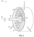
図4には、図1に示されている蒸気タービン50などの回転機械が示され、回転部品と静止部品の間のクリアランスを測定するために本技術の態様を組み込むことができる。蒸気タービン50は、シャフト54に取り付けられたロータ52を含む。複数のタービンブレード56(動翼(bucket)とも呼ばれる)が、ロータ52に取り付けられている。動作中は、ブレード56が高温高圧で蒸気58に曝され、その蒸気がブレード56を軸60の周りに回転させる。ブレード56は、ブレード16の周りに径方向、かつ円周方向に配置された静止ハウジングすなわちシュラウド62内部で回転する。相対的に小さいクリアランスが、ブレード56とシュラウド62の間に存在して、シュラウド62内部でブレード56が回転するのを容易にしながら、その小さいクリアランスによって、ブレード56とシュラウド62の間に作動流体すなわち蒸気の過度の漏れが妨げられる。本技術によれば、1つまたは複数のクリアランスセンサ64が、静止シュラウド62の周りの円周方向内側に配設される。示されている実施形態では、クリアランスセンサ64は容量性プローブを含む。実施形態によっては、クリアランスセンサ64は、マイクロ波ベースのセンサ、または光学式センサ、または渦電流センサを含んでもよく、感知されたパラメータはそれぞれ、インピーダンス、または位相遅れ、または誘起電流を含んでもよい。下記に詳細に説明するように、各センサ64は、シュラウド62の円周上の位置で、そのシュラウドに対するブレード56の径方向および軸方向の位置を示す信号を生成するように構成される。
FIG. 4 shows a rotating machine, such as the
次に図5を参照すると、図4の蒸気タービン10の底部分または下側部分70の断面図が示され、本技術によって測定することができる径方向および軸方向のクリアランスの例が示されている。示されている実施形態では、ブレード56の翼端は、シュラウド62の内側周辺部に設けられた溝74に噛合するパッキン歯すなわちシール歯72を含む。本実施形態では、クリアランス測定システム12(図1参照)は、ブレード56の翼端とシュラウド62の間の径方向および軸方向のクリアランスを測定するために、シュラウド62と結合してもよい。
Referring now to FIG. 5, a cross-sectional view of the bottom or
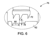
図6は、図5の蒸気タービンのシュラウドの部分76およびブレードの詳細断面図である。図に示すように、シール歯72とシュラウド62の間の径方向のクリアランスは、参照番号78で示され、歯72とシュラウド62の間の軸方向のクリアランスは、参照番号80で示される。本実施形態では、径方向、軸方向のクリアランス78、80は、中心の歯とシュラウドの間のクリアランスを表わす。残りのもう1つのシール歯とシュラウド62の間のクリアランスが、本技術によって同様に推定されてもよいことが当業者には理解されよう。
6 is a detailed cross-sectional view of the
実施形態によっては、シュラウド62とロータ56の熱膨張率が異なるので、径方向のクリアランス78がゼロまで縮まり、シール歯72と溝74が干渉する可能性がある。さらに、この膨張率の違いのために、ロータ56がシュラウド62に対して軸方向に伸びて、溝74内部の歯72が軸方向にこすれ、したがって構成部品の磨耗率が増大する可能性がある。こういった望ましくない干渉もまた、構成部品の損傷を招く恐れがある。本技術は、こういったクリアランスを許容される限界内の値に維持するように、閉ループ制御戦略に組み込むことができる、径方向、軸方向のクリアランス78、80のオンライン測定を提供する。この制御戦略には、例えばシュラウド62の熱動作が含まれてもよく、シュラウド62とシール歯72の間のクリアランスが減少すると、その戦略によってシュラウドが適切に広がる。この実施形態では、熱式アクチュエータが、シュラウド62の動きを生み出すために熱膨張の性質を利用する。他の実施形態によっては、シュラウド62内部のブレード56の軸方向の成長を補償するのに、機械式アクチュエータを使用してもよい。
In some embodiments, the thermal expansion coefficients of the
2つの物体の間の静電容量が、重なり合う表面積と、2つの物体の間の離隔距離の関数であることが当業者には理解されよう。この実施形態では、ロータ56とシュラウド62の間の静電容量は、径方向のクリアランス78と重なり合う面積の関数であり、重なり合う面積は、シュラウド62に対するシール歯72の軸方向のクリアランスに正比例する。ロータ56が径方向に広がると、シール歯72とシュラウド62の間の径方向のクリアランスが変化する。同様に、シール歯72が溝74を横切って軸方向に動くと、シール歯72に覆われているセンサヘッドの面積が変化する。これらの変化によって、測定される静電容量が変化する。下記に説明する本技術の態様によれば、静電容量の変化は、軸方向/径方向の変位と相関関係をもたせることができ、したがって合成クリアランス測定値を得ることができる。クリアランス測定システム12による径方向および軸方向のクリアランス78および80の測定値については、図7〜13と共に下記に詳細に説明する。
One skilled in the art will appreciate that the capacitance between two objects is a function of the overlapping surface area and the separation between the two objects. In this embodiment, the capacitance between the
図7には、図4および図5の蒸気タービンのノッチを有する回転部品82が示されている。示されている実施形態では、回転部品82は、回転軸の周りに連続する円形構造84を形成する、複数のブレードすなわち動翼56を含む。さらに回転部品82はまた、連続する円形構造84の連続性を遮る参照幾何形状86も含む。かかる参照幾何形状86の例には、窪み、ノッチ、溝、スロットなどの陥凹部が含まれる。
FIG. 7 shows a
動作中は、静止部品62上に配設されたセンサ64(図4参照)は、回転部品82(例えば、連続する円形幾何形状)から第1の感知パラメータを示す第1の信号を生成する。さらに、センサ64は、参照幾何形状86から第2の感知パラメータを示す第2の信号を生成する。この実施形態では、センサ64は容量性プローブを含み、第1および第2の感知パラメータは静電容量を含む。さらに、センサ64からの第1および第2の信号は、静止部品62と回転部品82の間の径方向および軸方向のクリアランスを推定するために、第1の感知パラメータと第2の感知パラメータの測定差に基づいて処理される。実施形態によっては、センサ64は、静止部品62と回転部品82の間の軸方向および径方向のクリアランスを測定するために、少なくとも2つのプローブ先端部を含むことができる。
In operation, a sensor 64 (see FIG. 4) disposed on the
示されている実施形態では、静止部品62と回転部品82の間の容量測定値をベースとした直流が、所定の深さを有する参照幾何形状86に基づく時間変動する容量測定値に変換される。実施形態によっては、参照幾何形状86は、回転部品82の材料以外の材料を含んでもよい。例えば、参照幾何形状86は、誘電材料で充填された、回転部品82上のノッチを含むことができる。図8は、図4のクリアランス測定システムによって図7のロータから測定された静電容量88のグラフである。容量測定値88の縦軸90は、センサ64によって回転部品82から感知された静電容量値を表し、横軸92は時間を表す。本実施形態では、センサ64によって生成された第1の信号は、回転部品82から感知された第1の静電容量を示し、参照番号94で示される。第1の静電容量は、センサ64と回転部品82(例えば、連続する円形幾何形状)の間のクリアランスを示す。さらに、センサ64はまた、参照番号96で示される参照幾何形状86(例えば、連続する円形幾何形状の陥凹部または切れ目)から感知された第2の静電容量を示す第2の信号も生成する。この実施形態では、第2の静電容量は、参照幾何形状86の深さ98に対応する。センサ64によって感知された第1と第2の静電容量の差と、参照幾何形状86の所定の深さ98が、静止部品62と回転部品82の間のクリアランスを決定するのに利用される。
In the illustrated embodiment, a direct current based on the capacitance measurement between
クリアランスが増大すると、回転部品82からの測定値と参照幾何形状86からの測定値との差が減少することが当業者には理解されよう。同様に、クリアランスが減少すると、かかる2つの測定の差は増大する。一般に、感知された静電容量は、静止部品62と回転部品82の間のクリアランスに反比例する。したがって、例示的な実施形態の場合、静止部品62と回転部品82の間のクリアランスが2倍になると、静止部品62と回転部品82の間の感知された静電容量の差は0.5の倍率で減少する。以下の例は、静止部品62と回転部品82の間のクリアランスの変化の効果を、感知された静電容量同士の測定差に基づいて示す。
Those skilled in the art will appreciate that as the clearance increases, the difference between the measurement from the
回転機械の例では、センサ64から間隔「a」のところにある回転部品82に対応するセンサ64からのセンサ出力が「x」で示される。さらに、間隔「a+b」のところにある参照幾何形状86(深さ「b」を有する)の底部に対応するセンサ出力が「y」で示される。静止部品62と回転部品82の間のクリアランスが「2a」に変化したとすると、かかるクリアランスに対応するセンサ64からの測定値は「x/2」になる。この実施形態では、参照幾何形状86の底部はセンサ64から間隔「2a+b」のところにある。したがって、第1の場合(間隔a)における回転部品82と参照幾何形状86に対応する信号の差は「x−y」になる。同様に、第2の場合(間隔2a)の信号の差は「x/2−y」になる。したがって、「a」から「2a」へのクリアランスの変化に対応する2つの測定値の差は、約x/2になる。
In the example of the rotating machine, the sensor output from the
したがって、示されている実施形態では、クリアランスは、参照幾何形状86の近傍で感知された静電容量値と、参照幾何形状86から離れたところで感知された静電容量値との測定差を利用することによって決定される。
Thus, in the illustrated embodiment, the clearance utilizes a measured difference between a capacitance value sensed in the vicinity of the
図9には、図4および図5の蒸気タービンの回転部品100の、他の例示的実施形態が示されている。示されている実施形態では、回転部品100は、連続する円形構造84に沿って配設されその連続性を遮る、段付きノッチ102などの多段レベルの参照幾何形状を含む。動作中は、センサ64が、回転部品100(例えば、連続する円形幾何形状)および、多段レベルの参照幾何形状102の異なるレベルに対応する、感知された静電容量を示す信号を生成する。その後、感知された静電容量同士の間の測定差に基づいて、静止部品72と回転部品100の間のクリアランスを推定するのに、かかる測定値を利用することができる。
FIG. 9 illustrates another exemplary embodiment of the
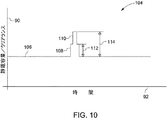
図10は、本技術の実施形態による図9のロータから、図3のクリアランス測定システムによって測定された静電容量104のグラフである。示されている実施形態では、センサ64は、参照番号106で示された、(多段レベル構造102から離れた)回転部品100の連続する円形表面に対応する静電容量を示す信号を生成する。さらに、センサ64は、参照番号108および110で示される、多段レベル構造102のレベルに対応する静電容量を示す信号も生成する。この場合も、感知された静電容量値は、参照幾何形状102の所定の深さ112および114に対応する。多段レベル構造102および回転部品100の表面の各レベルに対応する感知された静電容量の差は、静止部品62と回転部品100の間のクリアランスを決定するのに利用される。示されている実施形態では、回転部品100の表面と多段レベル構造102の異なるレベルの間の感知された静電容量同士の複数の差が、回転部品100の回転毎に得られる。さらに、かかる測定値が処理され、参照幾何形状102の測定差および所定の深さ112、114に基づいて、適切な参照テーブルを利用して、静止部品62と回転部品100の間のクリアランスを決定することができる。回転部品の回転毎に得られる、かかる複数の異なる測定値が、クリアランス測定システムの速度を大幅に高めるのが有利である。
FIG. 10 is a graph of
さらに、複数の測定値(例えば、段付きノッチ102の異なるレベルに対応する)を利用することによって、電子回路のドリフトなどの因子による、測定の任意のノイズ成分、静止部品62および回転部品100の材料特性の変化などがすべての測定値の間に等しく現れ得る。その後、測定値の差が推定されている間にそれらは打ち消される。したがって、多段レベル構造102などの参照幾何形状を用いることによって、かなり堅牢な、ドリフトに反応しないクリアランス測定システムによる測定が可能になる。
Furthermore, by utilizing multiple measurements (eg, corresponding to different levels of the stepped notch 102), any noise component of the measurement due to factors such as electronic circuit drift, the
図11には、図1の蒸気タービンの連続する表面幾何形状84上に配設され、その形状の連続性を遮る複数のノッチを有する回転部品の、別の例示的構造120が示されている。ここで企図されている構造では、回転部品120は、参照番号122、124、126、128および130で示されるような、複数の参照幾何形状またはノッチを含む。例えば、回転部品120は、多段レベルノッチ122と、連続する円形構造84の連続性を遮るための異なる深さを有する半円形のノッチ124、126、128および130を含んでもよい。示されている実施形態では、センサ64は、各ノッチ122、124、126、128および130に対応する静電容量を示す信号を生成する。感知されたパラメータ同士の間の複数の差が、回転部品120の回転毎に得られるので、複数のノッチ122、124、126、128および130を用いることによって、測定システムの速度が増すことが有利である。実施形態によっては、クリアランス測定システムを自己較正する手段として、かかる複数の差を用いることができる。
FIG. 11 illustrates another
さらに、その後かかる感知されたパラメータ(すなわち静電容量)は、複数のノッチ122、124、126、128および130の測定差および所定の深さに基づいて、静止部品62と回転部品120の間のクリアランスを決定するために処理される。示されている実施形態では、所定の幾何形状を有する複数のノッチ122、124、126、128および130に基づいた複数の測定値の測定の際の、ノイズ成分の影響を大幅に低減する。例えば、電子回路のドリフト、静止部品62および回転部品120の材料特性の変化などの因子による測定のノイズは、複数のノッチ122、124、126、128および130を用いることによって大幅に低減することができる。具体的には、ノイズ成分は全ての測定値の間に等しく現れる可能性があり、その後、測定値の差が推定されている間に打ち消される。したがって、回転部品120上に複数のノッチを用いることによって、かなり堅牢な、ドリフトに反応しないクリアランス測定システムによる測定が可能になる。
Further, such sensed parameter (ie, capacitance) is then determined between the
一般に、複数のノッチ122、124、126、128および130の各サイズは、各ノッチの側壁からの干渉を伴わず、かつノッチ122、124、126、128および130の底部からの信号の受信を容易にするために、プローブ先端のサイズと同じ程度のものである。さらに、ノッチ122、124、126、128および130の各サイズは、これらのノッチが蒸気タービンなどの回転機械の動力学または性能に影響を及ぼさないように選択される。概して、プローブ先端のサイズは一般に測定されるクリアランスと同じ程度のものである。例えば、蒸気タービンの適用例では、プローブ先端の直径は約5.1mm(200ミル)でよく、ノッチのサイズは半径が約3.2mm(125ミル)の半円形でよい。つまり、ノッチは幅が約6.3mm(250ミル)、深さが約3.2mm(125ミル)の半円形でよい。実施形態によっては、複数のノッチが用いられている場合、あるいは多段レベルノッチが用いられている場合、ノッチ段のサイズは、異なるレベルに対応する信号が正確に分解できるように選択することができる。例えば、センサの有効範囲が約3.8mm(150ミル)、クリアランスの予想される範囲が約2.5mm(100ミル)ならば、ノッチの段のサイズは1.3mm(50ミル)間隔になるように選択することができ、その結果、センサの動作範囲のほぼ全体にわたって、ノッチの様々なレベルが識別される。
In general, the size of each of the plurality of
上記に示すように、回転部品120と、122、124、126、128および130などの複数の参照幾何形状とに対応する静電容量を感知するために、センサ64を用いることができる。示されている実施形態では、センサ64は静電容量プローブである。実施形態によっては、容量性プローブ64は、回転機械の静止部品と回転部品の間の軸方向および径方向のクリアランスを測定するための少なくとも2つのプローブ先端を含む。上述のように、回転部品120とセンサ64の間の静電容量は、2つの変数、すなわち径方向のクリアランスおよび軸方向のクリアランスの関数である。したがって、2つのプローブの静電容量を測定することによって、変数(径方向および軸方向のクリアランス)の実際の値を得ることができる。
As indicated above,
図12には、図1および図4の蒸気タービンの、静止部品と回転部品の間のクリアランスを測定するために用いられるセンサ64の例示的構造132の平面図が示されている。示されている実施形態では、センサ132は、複数の容量性プローブ先端134、136、138および140を含み、これらの先端は、例えば導電性のシャフトを含んでもよい。示されている幾何形状と、プローブ134、136、138および140の相対位置によって、例えば1.27センチ(0.5インチ)を超える、軸方向の大きな変位範囲の測定が容易になり、例えば0.254ミリ(0.01インチ)の程度の変位を測定するための、径方向の測定値に望ましい分解能がもたらされる。上記の特徴は、回転部品14の軸方向の変位がシュラウド16に対する径方向の変位よりもかなり大きい適用例で有利である。
FIG. 12 shows a plan view of an
示されている実施形態では、プローブ134、136、138および140は、重なり合う領域の変化に対する感度を最大にするために、センサヘッド上に千鳥(staggered)形に配置され、ダイヤモンド形の構造を有する。他の千鳥構造が、より多い、またはより少ない数のプローブを有する実施形態で考案されてもよい。ヘッドまたは先端部分のプローブ134、136、138および140の直径は、それらとブレード14の翼端の間に重なり合う適切な表面積を与えるのに十分な、適当な大きさを有する。示されている実施形態では、すなわち蒸気タービン用途に対しては、プローブ134、136、138および140は、ニッケル、アルミニウム、コバルト、またはこれらの組み合わせ(Kovar(コバール、登録商標)など)を含む材料から形成することができる。ただし、より高い温度(例えば、1000℃を超える温度)を伴う用途では、プラチナ、ロジウム、またはそれらの組み合わせを含む材料をプローブ134、136、138、および140に使用することができる。
In the embodiment shown, probes 134, 136, 138 and 140 are arranged in a staggered form on the sensor head and have a diamond-shaped structure to maximize sensitivity to changes in the overlapping region. . Other staggered structures may be devised in embodiments having a greater or lesser number of probes. The diameters of the
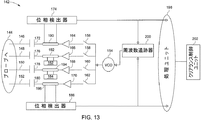
図13には、本技術の実施形態による図1〜4のクリアランス測定システムの例示的構造142が示されている。クリアランス測定システム142は、図12に関して上記に示したダイヤモンド形の構造に配置された4つのプローブ先端146、148、150および152を有するセンサ144を含む。さらに、信号発生器154が、入力励起信号をセンサ146、148、150および152に与えるために、プローブ先端146、148、150および152に結合されている。示されている実施形態では、信号発生器154は、電圧制御発振器(VCO)を含む。信号発生器154からの励起信号は、スイッチ156、158、160および162を介してプローブ先端146、148、150および152の間で切り替えることができる。実施形態によっては、プローブ先端146、148、150および152は、信号発生器154によって同時に励起される。あるいは、プローブ先端146、148、150および152は、それらの間の混信を低減するように、異なる時点で適時に励起されてもよい。
FIG. 13 illustrates an
さらに、プローブ先端146、148、150および152によってそれぞれ受け取られる入力信号を増幅するために、増幅器164、166、168および170を信号発生器154に結合することができる。示されている実施形態では、プローブ先端146を介して静電容量を測定するために、プローブ先端146にコンデンサ172および位相検出器174が結合されている。同様に、各プローブ先端を介して静電容量を測定するために、プローブ先端148、150、152に、それぞれコンデンサ176、178、180および位相検出器182、184、186を結合することができる。さらに、各プローブ先端からの入射信号と反射信号を分離するために、プローブ先端146、148、150、152に、方向性結合器190、192、194、196を結合することができる。
Further,
動作中は、プローブ先端146、148、150および152は、信号発生器154によって励起周波数で励起される。励起周波数は、配線長さ、静電容量、プローブ先端146、148、150、152の幾何形状、静的測定静電容量、および他の因子に基づいて選択することができる。ある実施形態では、位相検出器174、182、184および186は、回転部品14の表面などの第1の物体から第1の感知パラメータすなわち静電容量を示す第1の信号を生成するために、プローブ先端146、148、150および152からの反射信号を励起周波数に基づいて検出するように構成される。プローブ先端146、148、150および152を介した静電容量は、励起信号と対応する反射信号の間の位相差を、コンデンサ172、176、178および180と、位相検出器174、182、184および186で測定することによって測定される。同様に、第2の感知パラメータすなわち静電容量を示す第2の信号が、回転部品14上に配設された参照幾何形状からの励起信号と対応する反射信号の間の位相差を測定することによって、その参照幾何形状から生成される。実施形態によっては、図9および10に関して上記に示した、回転部品14上に配設された参照幾何形状の多重レベルに対応する複数の信号を生成してもよい。ある他の実施形態では、図11に関して上記で説明した、回転部品14の表面に配設された、複数の参照幾何形状に対応する複数の信号をセンサ144から生成することができる。
In operation, probe
次いで、センサ144から生成された第1および第2の信号を処理ユニット198によって処理することができる。さらに、信号発生器からの励起信号の周波数を周波数追跡ユニット200によって追跡し、制御することができる。動作中は、処理ユニット198は、回転部品14および回転部品14上に配設された参照幾何形状に対応する感知された静電容量を示す信号を受け取る。さらに、処理ユニット198は、回転部品14および参照幾何形状から感知された静電容量の測定差に基づいて、回転部品14と静止部品16の間のクリアランスを推定する。より具体的には、かかる感知された静電容量は、参照幾何形状の測定差および所定のサイズに基づいて、静止部品14と回転部品16の間のクリアランス決定するために処理される。
The first and second signals generated from
所定のサイズを有する参照幾何形状に基づいた測定値によって、電子回路のドリフト、静止部品14および回転部品16の材料特性の変化などの因子による測定の際のノイズ成分の影響が大幅に低減される。示されている実施形態では、ノイズ成分は、全ての測定値の間に等しく現れる可能性があり、その後、測定値の差が推定されている間に打ち消される。したがってこの実施形態では、処理ユニット198に受け取られた時間変動する信号は処理され、その信号の形状が抽出される。この実施形態では、信号の形状は基準線レベルおよびノッチ高さを含む。さらに、抽出されたノッチ高さは、ノッチの所定のサイズと比較される。測定されたノッチ高さは、クリアランスに応じてスケーリングされるので、複数の方法の1つを使用してクリアランスを決定することができる。これらの方法には、参照テーブル、解析/物理学ベースのモデル、またはカーブフィッティング機能が含まれる。上述のように、複数のかかる参照幾何形状が用いられてもよい。かかる参照幾何形状の所定のサイズによって、処理ユニット198は、測定による上記参照幾何形状のスケーリングを可能にするのに必要なクリアランスを決定する。したがって、測定値の絶対値ではなく測定値の差を使用して処理が行われるので、例えば比較的長い時間にわたって固定オフセット(時間変動なし、または徐々に変動する誤差)を導入するあらゆる測定誤差が取り除かれる。同様に、多段レベル幾何形状を使用すると、形状深さの複数の差について処理が行われるので、あらゆる利得誤差も取り除くことができる。概して、簡単なノッチを用いることによってオフセット(徐々に変動する)誤差を取り除くことができ、多段レベル幾何形状を使用することによって利得/スケーリングの誤差を取り除くことができる。
Measurements based on a reference geometry having a predetermined size greatly reduce the effects of noise components during measurement due to factors such as electronic circuit drift and changes in material properties of stationary and
したがって、回転部品14の連続する表面幾何形状の連続性を参照幾何形状によって遮ることによって、クリアランス測定システム142は、回転部品14と静止部品16の間の直流をベースとした容量測定値を時間変動する容量測定値に変換する。より具体的には、連続する表面幾何形状の連続性を参照幾何形状によって遮ることによって、容量性プローブによって生成された信号に、感知システムを自己較正するのに使用でき、かつ測定値が信号ドリフトの影響を受けないようにするスパイク波形が導入される。
Thus, by blocking the continuity of the continuous surface geometry of the
上述のように、かかる時間変動する容量測定値は、回転部品14と静止部品16の間のクリアランスを推定するために利用される。実施形態によっては、処理ユニット198は、参照テーブル、または較正曲線、または感知された静電容量と回転部品14上に配設された参照幾何形状の所定のサイズの測定差に基づいてクリアランスを推定するための他の技術を使用してもよい。さらに、処理ユニット198によって推定されたクリアランスに基づいて、回転部品と静止部品の間のクリアランスを制御するために、クリアランス制御ユニット202を処理ユニット198に結合することができる。
As described above, such time-varying capacitance measurements are used to estimate the clearance between the
図14は、本技術の実施形態による図13のクリアランス測定システムによって測定されたセンサ出力204のグラフである。出力204の縦軸は、プローブ先端から測定されたノッチ高さ206を表し、横軸は、回転部品14と静止部品16の間の測定された軸方向のクリアランス208をミル単位で表す。示されている実施形態では、グラフ210、212は、図12に示す同じ径方向位置に配置された2つのプローブ先端136、140から測定されたノッチ高さを表す。さらに、曲線214、216は、プローブ先端136および140の左側、右側に配置されたプローブ先端138、134から測定されたノッチ高さを表す。本実施形態では、測定されたノッチ高さ206は、静止体と回転体の間のクリアランスの尺度である。
14 is a graph of
図に示すように、ノッチ高さ206で代表されるノッチなどの参照幾何形状の電気的記号は、ノッチ高さに応じて変化する。ノッチ高さは、軸方向および径方向変位の関数である。例えば、プローブ先端136がノッチにかなり近接するときは、プローブ先端から受け取る信号が曲線218で示される。さらに、プローブ先端136が移動してノッチから離れると、信号は曲線220および224で示される。したがって、ノッチから受け取る信号は、ノッチ高さと、プローブ先端134、136、138および140からのノッチの間隔に応じて変化する。回転部品と静止部品の間の径方向のクリアランスが増大すると、プローブ先端134、136、138および138から感知された出力が低減する。例えば、参照番号226で示される径方向の変位の増加量は、プローブ先端136からの信号218、220、222および224に反映される。同様に、他のプローブ先端134、138および140からの信号が、曲線210、212および216で示されるように、ノッチ高さおよびプローブ先端からの間隔に応答して変化する。
As shown, the electrical symbol of a reference geometry, such as a notch represented by the
上記に説明した方法の様々な態様は、様々な用途で効用を有する。例えば、上記に例示した技術は、蒸気タービンの回転部品と静的部品の間のクリアランスを測定するのに使用することができる。この技術は、例えば発電機の静止部品と回転部品の間のクリアランスを測定するなど、他のある種の用途に使用することもできる。上述したように、さらに一般的には、本明細書に記載の方法は、静止部品と回転部品の間の直流をベースとした容量測定値を、回転部品の連続する表面幾何形状を遮る少なくとも1つの参照幾何形状に基づく時間変動する容量測定値に変換することによって、センサによる物体同士の間のクリアランスの正確な測定が可能になることが有利になり得る。さらに、この技術は、動作中でさえ長期間にわたって、部品のクリアランスを正確に測定し、動作中に、より優れた、部品のクリアランス制御を可能にするための自己較正センサシステムを実現することが特に有利である。 Various aspects of the method described above have utility in a variety of applications. For example, the techniques illustrated above can be used to measure the clearance between rotating and static parts of a steam turbine. This technique can also be used for certain other applications, such as measuring the clearance between stationary and rotating parts of a generator. As discussed above, more generally, the methods described herein provide a DC-based capacitance measurement between a stationary component and a rotating component that is at least one that blocks a continuous surface geometry of the rotating component. By converting to a time-varying volumetric measurement based on one reference geometry, it may be advantageous to allow an accurate measurement of the clearance between objects by the sensor. In addition, this technology can accurately measure part clearance over a long period of time even during operation, enabling a self-calibrating sensor system to allow better part clearance control during operation. Particularly advantageous.
本発明のある種の特徴だけを本明細書に例示し、説明したが、多くの改変および変更を当業者なら思いつくであろう。したがって、添付の特許請求の範囲は、本発明の本来の趣旨の範囲内に入る改変および変更を全て包含するためのものであることを理解されたい。 While only certain features of the invention have been illustrated and described herein, many modifications and changes will occur to those skilled in the art. Accordingly, it is to be understood that the appended claims are intended to cover all such modifications and changes as fall within the true spirit of the invention.
10 蒸気タービン
12 クリアランス測定システム
14 回転部品
16 静止部品
20 キャリアなしの蒸気タービン
22 蒸気タービンの段
24 回転動翼
26 回転の方向
30 発電機
32 フレーム組立体
34 ロータ組立体
36 ロータシャフト
38 ロータコア
40 ロータラミネーション
42 ステータ組立体
44 回転の方向
46 ステータ巻線
50 蒸気タービン
52 ロータ
54 シャフト
56 回転動翼
58 蒸気
60 回転軸
62 ケーシング/キャリア
64 センサ
70 蒸気タービン−ステータ/ロータ構造
72 シール歯
74 ステータ溝
76 詳細図
78 径方向のクリアランス
80 軸方向のクリアランス
82 ノッチを有するロータ
84 ロータの連続する表面
86 ノッチ
88 静電容量/クリアランス測定値と時間の関係
90 静電容量/クリアランス
92 時間
94 表面からの信号
96 ノッチからの信号
98 ノッチの深さ
100 多段レベルノッチを有するロータ
102 多段レベルノッチ
104 静電容量/クリアランス測定値と時間の関係
106 表面からの信号
108 ノッチからの信号
110 ノッチからの信号
112 ノッチの第1の深さ
114 ノッチの第2の深さ
120 複数のノッチを有するロータ
122〜130 ノッチ
132 センサ
134〜140 プローブ先端
142 クリアランス測定システム
146〜152 プローブ先端
154 VCO
156〜162 スイッチ
164〜170 増幅器
172〜180 コンデンサ
190〜196 方向性結合器
174〜186 位相検出器
198 処理連鎖
200 周波数追跡器
202 クリアランス制御ユニット
204 センサ出力と軸方向のクリアランスの関係
206 センサ出力
208 軸方向のクリアランス
210 先端1からの出力
212 先端3からの出力
214 先端4からの出力
216 先端2からの出力
218〜224 センサ先端1からの出力
216 増大する径方向のクリアランス
DESCRIPTION OF
156 to 162
Claims (10)
通常なら連続する表面幾何形状を有する第1の物体(14)上に配設された参照幾何形状(86)と、第2の物体(16)上に配設されたセンサ(64)と、処理ユニット(198)とを含み、
前記センサ(64)は、前記第1の物体(14)からの第1の感知パラメータを示す第1の信号と、前記参照幾何形状(86)からの第2の感知パラメータを示す第2の信号とを生成するように構成され、
前記処理ユニット(198)は、前記第1と第2の物体(14、16)の間のクリアランスを推定するために、前記第1および第2の感知パラメータの間の測定差に基づいて、前記第1および第2の信号を処理するように構成された、クリアランス測定システム(12)。 A clearance measurement system (12),
A reference geometry (86) disposed on a first object (14) having a normally continuous surface geometry, a sensor (64) disposed on a second object (16), and processing Unit (198) and
The sensor (64) has a first signal indicative of a first sensing parameter from the first object (14) and a second signal indicative of a second sensing parameter from the reference geometry (86). And is configured to generate
The processing unit (198) is configured to estimate the clearance between the first and second objects (14, 16) based on the measured difference between the first and second sensing parameters. A clearance measurement system (12) configured to process the first and second signals.
前記第1の物体(14)および前記参照幾何形状(86)のそれぞれからの複数の反射信号を検出し、各前記反射信号とそれぞれの励起信号の間の位相を決定するために複数の位相測定を行うように構成された位相検出器(174)とをさらに含む、請求項1記載のシステム(12)。 An excitation source (154) configured to provide an excitation signal to the sensor (64);
A plurality of phase measurements to detect a plurality of reflected signals from each of the first object (14) and the reference geometry (86) and determine a phase between each of the reflected signals and a respective excitation signal The system (12) of claim 1, further comprising a phase detector (174) configured to:
前記回転部品(14)の前記連続する表面上に配設された参照幾何形状(86)と、
前記回転部品(14)、前記参照幾何形状(86)にそれぞれ対応する第1、第2の感知パラメータを示す第1、第2の信号を生成するように構成されたセンサ(64)と、
前記回転部品(14)と静止部品(16)の間のクリアランスを推定するために、前記第1と第2の感知パラメータの間の測定差に基づいて、前記第1および第2の信号を処理するように構成された、処理ユニット(198)とを備える、回転機械(10)。 A rotating component (14) spaced apart from the stationary component (16), including a surface continuous in its rotational direction;
A reference geometry (86) disposed on the continuous surface of the rotating component (14);
A sensor (64) configured to generate first and second signals indicative of first and second sensing parameters respectively corresponding to the rotating component (14) and the reference geometry (86);
Process the first and second signals based on a measured difference between the first and second sensing parameters to estimate a clearance between the rotating component (14) and a stationary component (16). A rotating machine (10) comprising a processing unit (198) configured to:
前記第2の物体上に配設された前記センサによって、前記第1の物体の連続する表面幾何形状上に配設された参照幾何形状に対応する第2の感知パラメータを示す第2の信号を生成するステップと、
前記第1と第2の物体の間のクリアランスを推定するために、前記第1と第2の感知パラメータの間の測定差に基づいて、前記第1および第2の信号を処理するステップとを含む、第1の物体と第2の物体の間のクリアランスを測定する方法。 Generating a first signal indicative of a first sensing parameter corresponding to the first object by a sensor disposed on the second object;
A second signal indicative of a second sensing parameter corresponding to a reference geometry disposed on a continuous surface geometry of the first object by the sensor disposed on the second object. Generating step;
Processing the first and second signals based on a measured difference between the first and second sensing parameters to estimate a clearance between the first and second objects; A method for measuring a clearance between a first object and a second object.
直流をベースとした容量測定値を、第1と第2の物体の間の時間変動する容量測定値に変換する手段と、
前記第1と第2の物体の間のクリアランスを推定するために、前記時間変動する容量測定値を処理する手段とを含む、第1の物体と第2の物体の間のクリアランスを測定するシステム。 Means for generating a capacitance measurement between the first and second objects;
Means for converting a capacitance measurement based on direct current into a time-varying capacitance measurement between the first and second objects;
A system for measuring a clearance between a first object and a second object including means for processing the time-varying capacitance measurement to estimate a clearance between the first and second objects. .
前記回転部品(14)と前記静止部品(16)とに結合されたクリアランス測定システム(12)とを備える回転機械(10)であって、前記クリアランス測定システム(12)が、前記少なくとも1つの参照幾何形状(86)に基づいて、直流をベースとした前記回転部品(14)と静止部品(16)の間の容量測定値を時間変動する容量測定値に変換し、前記時間変動する容量測定値に基づいて前記回転部品(14)と静止部品(16)の間のクリアランスを推定するように構成される、回転機械(10)。 A continuous circular structure spaced apart from the stationary part (16) and having at least one reference geometry (86), said at least one reference geometry (86) being said continuous around its axis of rotation A rotating part (14) blocking the continuity of the circular structure;
A rotating machine (10) comprising a clearance measuring system (12) coupled to the rotating part (14) and the stationary part (16), wherein the clearance measuring system (12) is the at least one reference. Based on the geometric shape (86), the capacitance measurement value between the rotating component (14) and the stationary component (16) based on direct current is converted into a capacitance measurement value that varies with time, and the capacitance measurement value that varies with time is obtained. A rotating machine (10) configured to estimate a clearance between the rotating part (14) and the stationary part (16) based on
Applications Claiming Priority (2)
| Application Number | Priority Date | Filing Date | Title |
|---|---|---|---|
| US11/167,434 US7333913B2 (en) | 2005-06-27 | 2005-06-27 | Clearance measurement system and method of operation |
| US11/167,434 | 2005-06-27 |
Publications (2)
| Publication Number | Publication Date |
|---|---|
| JP2007010656A true JP2007010656A (en) | 2007-01-18 |
| JP5221011B2 JP5221011B2 (en) | 2013-06-26 |
Family
ID=37007410
Family Applications (1)
| Application Number | Title | Priority Date | Filing Date |
|---|---|---|---|
| JP2006175214A Expired - Fee Related JP5221011B2 (en) | 2005-06-27 | 2006-06-26 | Clearance measurement system and operation method |
Country Status (7)
| Country | Link |
|---|---|
| US (1) | US7333913B2 (en) |
| EP (1) | EP1739387B1 (en) |
| JP (1) | JP5221011B2 (en) |
| CN (1) | CN1892172B (en) |
| AT (1) | ATE467809T1 (en) |
| DE (1) | DE602006014232D1 (en) |
| ES (1) | ES2343077T3 (en) |
Cited By (5)
| Publication number | Priority date | Publication date | Assignee | Title |
|---|---|---|---|---|
| JP2009238226A (en) * | 2008-03-25 | 2009-10-15 | General Electric Co <Ge> | System and method for online phase calibration |
| JP2010085405A (en) * | 2008-09-29 | 2010-04-15 | Rosemount Aerospace Inc | Blade tip clearance measurement sensor and method for gas turbine engines |
| JP2010175539A (en) * | 2009-01-27 | 2010-08-12 | General Electric Co <Ge> | Automatic calibration of sensor by sensor parameter download |
| JP2013139793A (en) * | 2012-01-03 | 2013-07-18 | General Electric Co <Ge> | Method and apparatus for obtaining discrete axial clearance data using radial clearance sensor |
| JP2013250266A (en) * | 2012-05-31 | 2013-12-12 | General Electric Co <Ge> | Rotation clearance measuring system and operating method |
Families Citing this family (38)
| Publication number | Priority date | Publication date | Assignee | Title |
|---|---|---|---|---|
| US7631498B2 (en) * | 2005-10-11 | 2009-12-15 | Honeywell International Inc. | Bearing health monitor |
| US7605595B2 (en) * | 2006-09-29 | 2009-10-20 | General Electric Company | System for clearance measurement and method of operating the same |
| DE102006060650A1 (en) * | 2006-12-21 | 2008-06-26 | Mtu Aero Engines Gmbh | Device and method for contactless blade vibration measurement |
| US8177474B2 (en) * | 2007-06-26 | 2012-05-15 | General Electric Company | System and method for turbine engine clearance control with rub detection |
| US7852092B2 (en) * | 2008-03-25 | 2010-12-14 | General Electric Company | Systems for inspection of shrouds |
| US7853427B2 (en) * | 2008-05-12 | 2010-12-14 | General Electric Company | Clearance estimation system and method for a rotary machine |
| US8272246B2 (en) * | 2008-09-30 | 2012-09-25 | General Electric Company | Electronic self-calibration for sensor clearance |
| US7916311B2 (en) * | 2008-10-31 | 2011-03-29 | General Electric Company | Method and system for inspecting blade tip clearance |
| US8451459B2 (en) | 2008-10-31 | 2013-05-28 | General Electric Company | Method and system for inspecting blade tip clearance |
| US8121813B2 (en) * | 2009-01-28 | 2012-02-21 | General Electric Company | System and method for clearance estimation between two objects |
| EP2218881A1 (en) * | 2009-02-13 | 2010-08-18 | Siemens Aktiengesellschaft | Method for online calibration of a sensor and measuring system |
| US8342798B2 (en) * | 2009-07-28 | 2013-01-01 | General Electric Company | System and method for clearance control in a rotary machine |
| IT1400054B1 (en) * | 2010-05-31 | 2013-05-17 | Nuova Pignone S R L | DEVICE AND METHOD FOR DISTANCE ANALYZER |
| US8593296B2 (en) * | 2010-10-19 | 2013-11-26 | General Electric Company | System and method for turbine bucket tip shroud deflection measurement |
| JP5074608B2 (en) * | 2011-02-08 | 2012-11-14 | 田中貴金属工業株式会社 | Probe pin |
| CN102331221B (en) * | 2011-06-07 | 2013-04-03 | 力帆实业(集团)股份有限公司 | Magneto gap measuring tool of motorcycle engine |
| US8876460B2 (en) * | 2011-08-11 | 2014-11-04 | General Electric Company | Method and apparatus for measuring turbine shell clearance |
| US9046050B2 (en) * | 2011-09-15 | 2015-06-02 | General Electric Company | Shaft imbalance detection system |
| US20130073172A1 (en) * | 2011-09-15 | 2013-03-21 | Bret Dwayne Worden | Detection system and method |
| US20130171611A1 (en) * | 2012-01-03 | 2013-07-04 | General Electric Company | Apparatus for simulating operation of fan blades in a gas turbine |
| US9417048B2 (en) | 2012-10-31 | 2016-08-16 | General Electric Company | Capacitive sensor device and method of manufacture |
| US9279655B2 (en) * | 2013-02-26 | 2016-03-08 | The United States Of America As Represented By The Secretary Of The Navy | Non-contact electrical machine air gap measurement tool |
| CN103206916B (en) * | 2013-03-26 | 2015-08-05 | 洛阳轴研科技股份有限公司 | A kind of signal acquisition method with V-notch revolving meber rotational angle |
| ES2574436T3 (en) * | 2013-05-22 | 2016-06-17 | Mtu Aero Engines Gmbh | Turbomachinery degree and method for determining a sealing groove and / or an axial position of such a turbomachinery degree |
| EP2806110A1 (en) * | 2013-05-22 | 2014-11-26 | MTU Aero Engines GmbH | Turbo engine stage and method for determining a seal gap of such a turbo engine stage |
| US9476318B2 (en) * | 2013-09-03 | 2016-10-25 | General Electric Company | Systems and methods to monitor a rotating component |
| DE102013217998A1 (en) * | 2013-09-09 | 2015-03-12 | Siemens Aktiengesellschaft | Method for determining a gap size |
| US9341462B2 (en) | 2013-10-09 | 2016-05-17 | Siemens Energy, Inc | Sensor for measuring blade tip clearance in gas turbines |
| US9587511B2 (en) | 2013-12-13 | 2017-03-07 | General Electric Company | Turbomachine cold clearance adjustment |
| US9568301B2 (en) * | 2014-04-11 | 2017-02-14 | General Electric Company | Systems and methods for capacitive proximity sensing |
| FR3050523B1 (en) * | 2016-04-20 | 2018-04-20 | Safran Electronics & Defense | METHOD OF ESTIMATING THE PLAY OF AN ELECTRO-MECHANICAL ACTUATOR |
| CN106767606A (en) * | 2017-03-21 | 2017-05-31 | 重庆大学 | Quimby pump rotor interference detection method based on rigging error |
| US10222200B2 (en) * | 2017-05-12 | 2019-03-05 | Siemens Energy, Inc. | Contactless, blade-tip clearance measurement for turbines |
| US11043146B2 (en) * | 2018-08-20 | 2021-06-22 | Raytheon Technologies Corporation | Fan blade refurbishment training device |
| CN110986809B (en) * | 2019-12-23 | 2021-07-02 | 中车株洲电机有限公司 | Method and device for measuring radial clearance of motor bearing assembly |
| CN111288952B (en) * | 2020-03-16 | 2022-07-05 | 湖南米艾西测控技术有限公司 | Automatic centering adjusting tool for rotary transformer |
| CN113654427B (en) * | 2021-06-29 | 2022-09-06 | 中国电建集团山东电力建设第一工程有限公司 | Tool and method for measuring moving and static positions of zero-bearing supported intermediate pressure cylinder during false tile removal |
| CN114152196A (en) * | 2021-11-30 | 2022-03-08 | 四川航天烽火伺服控制技术有限公司 | Motor rotor assembly quality comprehensive detection equipment |
Citations (30)
| Publication number | Priority date | Publication date | Assignee | Title |
|---|---|---|---|---|
| JPS55135703A (en) * | 1979-04-10 | 1980-10-22 | Mitsubishi Heavy Ind Ltd | Measuring method of gap sensor |
| JPS58166202A (en) * | 1982-03-27 | 1983-10-01 | Nippon Steel Corp | Device for measuring thickness of multiple layers of dielectric |
| JPS5960006A (en) * | 1982-08-31 | 1984-04-05 | ウエスチングハウス エレクトリツク コ−ポレ−シヨン | Monitor apparatus of turbine blade |
| JPS63167002A (en) * | 1986-12-22 | 1988-07-11 | ウエスチングハウス・エレクトリック・コーポレーション | Method of inspecting tightness of turbine shroud section |
| JPS6413408A (en) * | 1987-07-07 | 1989-01-18 | Kyocera Corp | Reference disk |
| JPH01210802A (en) * | 1988-02-01 | 1989-08-24 | Internatl Business Mach Corp <Ibm> | Device for measuring vertical distance between two object and device for controlling said vertical distance |
| JPH0223205A (en) * | 1988-05-27 | 1990-01-25 | Westinghouse Electric Corp <We> | Method and device for monitoring clearance of turbine blade shroud |
| US4987555A (en) * | 1988-11-30 | 1991-01-22 | Westinghouse Electric Corp. | Turbine blade shroud clearance monitor |
| JPH0337502A (en) * | 1989-07-03 | 1991-02-18 | Naoyuki Omatoi | Electrostatic capacitance type range finder |
| JPH0422803A (en) * | 1990-05-18 | 1992-01-27 | Westinghouse Canada Inc | Method and meter for measuring relative position of plurality of surface in hole |
| JPH0471114U (en) * | 1990-10-30 | 1992-06-24 | ||
| JPH04231802A (en) * | 1990-05-29 | 1992-08-20 | General Electric Co <Ge> | Electric-capacitance gap meter |
| US5166626A (en) * | 1990-05-29 | 1992-11-24 | General Electric Company | Electrical capacitance clearanceometer |
| JPH05500113A (en) * | 1989-09-05 | 1993-01-14 | イーストマン・コダック・カンパニー | capacitive probe |
| JPH0523014U (en) * | 1991-08-30 | 1993-03-26 | 三菱重工業株式会社 | Blade turbine shroud clearance determination device for steam turbine |
| JPH06147917A (en) * | 1992-11-05 | 1994-05-27 | Kayaba Ind Co Ltd | Position detector |
| JPH07198309A (en) * | 1991-06-11 | 1995-08-01 | Weidmueller Interface Gmbh & Co | Capacitance sensor device |
| JPH07198312A (en) * | 1993-11-17 | 1995-08-01 | Soc Natl Etud Constr Mot Aviat <Snecma> | Device for dynamically measuring distance between facing surfaces of rotor and stator in rotary machine |
| JPH08101009A (en) * | 1994-08-12 | 1996-04-16 | Dr Johannes Heidenhain Gmbh | Position measuring device |
| US5552884A (en) * | 1994-12-16 | 1996-09-03 | Seagate Technology, Inc. | Calibration standard for flying height tester having a head mounted on a multilevel surface transparent disc |
| JPH08338851A (en) * | 1995-04-11 | 1996-12-24 | Nippondenso Co Ltd | Magnetic detector |
| JPH1181902A (en) * | 1997-09-02 | 1999-03-26 | Honda Motor Co Ltd | Method of balancing turbine rotor |
| JP2000220408A (en) * | 1999-02-01 | 2000-08-08 | Ishikawajima Harima Heavy Ind Co Ltd | Method for measuring blade tip clearance of ceramic rotor blade |
| JP2000234903A (en) * | 1999-02-16 | 2000-08-29 | Precitec Gmbh | Method for measuring interval between sensor electrode and workpiece |
| JP2001330406A (en) * | 2000-05-19 | 2001-11-30 | Fujitsu Ltd | Interval measuring method and sensor for measuring interval |
| JP2002131011A (en) * | 2000-10-26 | 2002-05-09 | Hitachi Ltd | Detector for reduction of gap |
| JP2003042745A (en) * | 2001-08-02 | 2003-02-13 | Mitsubishi Heavy Ind Ltd | Rotor blade life evaluating device and method and axial blower |
| JP2004502930A (en) * | 2000-07-06 | 2004-01-29 | スネクマ・モトウール | Sensor for measuring gaps due to wear at multiple depths |
| JP2004150431A (en) * | 2002-10-31 | 2004-05-27 | General Electric Co <Ge> | Apparatus and method for inspecting dovetail slot width for gas turbine engine disk |
| JP2005525494A (en) * | 2002-05-14 | 2005-08-25 | 本田技研工業株式会社 | Gas turbine engine with active tip clearance control |
Family Cites Families (12)
| Publication number | Priority date | Publication date | Assignee | Title |
|---|---|---|---|---|
| US4049349A (en) * | 1976-06-30 | 1977-09-20 | Wennerstrom Arthur J | Device for measuring rotor tip clearance in operating turbomachinery |
| DE3433351C1 (en) * | 1984-09-11 | 1986-01-02 | MTU Motoren- und Turbinen-Union München GmbH, 8000 München | Capacitive measuring system for measuring the distance between two parts that are movable relative to each other |
| US4818948A (en) * | 1986-08-05 | 1989-04-04 | Pratt & Whitney Canada Inc. | Capacitive bridge-type probe for measuring blade tip clearance |
| US4842477A (en) * | 1986-12-24 | 1989-06-27 | General Electric Company | Active clearance control |
| US4928089A (en) * | 1987-12-21 | 1990-05-22 | Pitney Bowes Inc. | Hall effect printwheel encoder |
| US5097711A (en) * | 1990-10-29 | 1992-03-24 | Westinghouse Electric Corp. | Shrouded turbine blade vibration monitor and target therefor |
| US5929752A (en) * | 1993-11-24 | 1999-07-27 | Trimble Navigation Limited | Clandestine missing vehicle location reporting using cellular channels |
| GB2312958B (en) | 1996-05-09 | 1998-04-15 | Rotadata Ltd | Analysis of motion of rotary assembly |
| US6785635B2 (en) * | 1999-08-02 | 2004-08-31 | Hood Technology Corporation | Apparatus and method for predicting failures of spinning disks in turbo-machinery |
| US6594555B2 (en) * | 2000-12-21 | 2003-07-15 | General Electric Company | Method for steam turbine halfshell alignment |
| US6848193B1 (en) * | 2003-11-26 | 2005-02-01 | General Electric Company | Methods and systems for machine monitoring system calibration |
| US7722310B2 (en) * | 2004-12-17 | 2010-05-25 | General Electric Company | System and method for measuring clearance between two objects |
-
2005
- 2005-06-27 US US11/167,434 patent/US7333913B2/en active Active
-
2006
- 2006-06-26 EP EP06253303A patent/EP1739387B1/en not_active Not-in-force
- 2006-06-26 DE DE602006014232T patent/DE602006014232D1/en active Active
- 2006-06-26 JP JP2006175214A patent/JP5221011B2/en not_active Expired - Fee Related
- 2006-06-26 AT AT06253303T patent/ATE467809T1/en not_active IP Right Cessation
- 2006-06-26 ES ES06253303T patent/ES2343077T3/en active Active
- 2006-06-27 CN CN2006101000447A patent/CN1892172B/en not_active Expired - Fee Related
Patent Citations (30)
| Publication number | Priority date | Publication date | Assignee | Title |
|---|---|---|---|---|
| JPS55135703A (en) * | 1979-04-10 | 1980-10-22 | Mitsubishi Heavy Ind Ltd | Measuring method of gap sensor |
| JPS58166202A (en) * | 1982-03-27 | 1983-10-01 | Nippon Steel Corp | Device for measuring thickness of multiple layers of dielectric |
| JPS5960006A (en) * | 1982-08-31 | 1984-04-05 | ウエスチングハウス エレクトリツク コ−ポレ−シヨン | Monitor apparatus of turbine blade |
| JPS63167002A (en) * | 1986-12-22 | 1988-07-11 | ウエスチングハウス・エレクトリック・コーポレーション | Method of inspecting tightness of turbine shroud section |
| JPS6413408A (en) * | 1987-07-07 | 1989-01-18 | Kyocera Corp | Reference disk |
| JPH01210802A (en) * | 1988-02-01 | 1989-08-24 | Internatl Business Mach Corp <Ibm> | Device for measuring vertical distance between two object and device for controlling said vertical distance |
| JPH0223205A (en) * | 1988-05-27 | 1990-01-25 | Westinghouse Electric Corp <We> | Method and device for monitoring clearance of turbine blade shroud |
| US4987555A (en) * | 1988-11-30 | 1991-01-22 | Westinghouse Electric Corp. | Turbine blade shroud clearance monitor |
| JPH0337502A (en) * | 1989-07-03 | 1991-02-18 | Naoyuki Omatoi | Electrostatic capacitance type range finder |
| JPH05500113A (en) * | 1989-09-05 | 1993-01-14 | イーストマン・コダック・カンパニー | capacitive probe |
| JPH0422803A (en) * | 1990-05-18 | 1992-01-27 | Westinghouse Canada Inc | Method and meter for measuring relative position of plurality of surface in hole |
| JPH04231802A (en) * | 1990-05-29 | 1992-08-20 | General Electric Co <Ge> | Electric-capacitance gap meter |
| US5166626A (en) * | 1990-05-29 | 1992-11-24 | General Electric Company | Electrical capacitance clearanceometer |
| JPH0471114U (en) * | 1990-10-30 | 1992-06-24 | ||
| JPH07198309A (en) * | 1991-06-11 | 1995-08-01 | Weidmueller Interface Gmbh & Co | Capacitance sensor device |
| JPH0523014U (en) * | 1991-08-30 | 1993-03-26 | 三菱重工業株式会社 | Blade turbine shroud clearance determination device for steam turbine |
| JPH06147917A (en) * | 1992-11-05 | 1994-05-27 | Kayaba Ind Co Ltd | Position detector |
| JPH07198312A (en) * | 1993-11-17 | 1995-08-01 | Soc Natl Etud Constr Mot Aviat <Snecma> | Device for dynamically measuring distance between facing surfaces of rotor and stator in rotary machine |
| JPH08101009A (en) * | 1994-08-12 | 1996-04-16 | Dr Johannes Heidenhain Gmbh | Position measuring device |
| US5552884A (en) * | 1994-12-16 | 1996-09-03 | Seagate Technology, Inc. | Calibration standard for flying height tester having a head mounted on a multilevel surface transparent disc |
| JPH08338851A (en) * | 1995-04-11 | 1996-12-24 | Nippondenso Co Ltd | Magnetic detector |
| JPH1181902A (en) * | 1997-09-02 | 1999-03-26 | Honda Motor Co Ltd | Method of balancing turbine rotor |
| JP2000220408A (en) * | 1999-02-01 | 2000-08-08 | Ishikawajima Harima Heavy Ind Co Ltd | Method for measuring blade tip clearance of ceramic rotor blade |
| JP2000234903A (en) * | 1999-02-16 | 2000-08-29 | Precitec Gmbh | Method for measuring interval between sensor electrode and workpiece |
| JP2001330406A (en) * | 2000-05-19 | 2001-11-30 | Fujitsu Ltd | Interval measuring method and sensor for measuring interval |
| JP2004502930A (en) * | 2000-07-06 | 2004-01-29 | スネクマ・モトウール | Sensor for measuring gaps due to wear at multiple depths |
| JP2002131011A (en) * | 2000-10-26 | 2002-05-09 | Hitachi Ltd | Detector for reduction of gap |
| JP2003042745A (en) * | 2001-08-02 | 2003-02-13 | Mitsubishi Heavy Ind Ltd | Rotor blade life evaluating device and method and axial blower |
| JP2005525494A (en) * | 2002-05-14 | 2005-08-25 | 本田技研工業株式会社 | Gas turbine engine with active tip clearance control |
| JP2004150431A (en) * | 2002-10-31 | 2004-05-27 | General Electric Co <Ge> | Apparatus and method for inspecting dovetail slot width for gas turbine engine disk |
Cited By (5)
| Publication number | Priority date | Publication date | Assignee | Title |
|---|---|---|---|---|
| JP2009238226A (en) * | 2008-03-25 | 2009-10-15 | General Electric Co <Ge> | System and method for online phase calibration |
| JP2010085405A (en) * | 2008-09-29 | 2010-04-15 | Rosemount Aerospace Inc | Blade tip clearance measurement sensor and method for gas turbine engines |
| JP2010175539A (en) * | 2009-01-27 | 2010-08-12 | General Electric Co <Ge> | Automatic calibration of sensor by sensor parameter download |
| JP2013139793A (en) * | 2012-01-03 | 2013-07-18 | General Electric Co <Ge> | Method and apparatus for obtaining discrete axial clearance data using radial clearance sensor |
| JP2013250266A (en) * | 2012-05-31 | 2013-12-12 | General Electric Co <Ge> | Rotation clearance measuring system and operating method |
Also Published As
| Publication number | Publication date |
|---|---|
| CN1892172B (en) | 2011-09-07 |
| DE602006014232D1 (en) | 2010-06-24 |
| ATE467809T1 (en) | 2010-05-15 |
| ES2343077T3 (en) | 2010-07-22 |
| JP5221011B2 (en) | 2013-06-26 |
| EP1739387B1 (en) | 2010-05-12 |
| US7333913B2 (en) | 2008-02-19 |
| US20070005294A1 (en) | 2007-01-04 |
| EP1739387A1 (en) | 2007-01-03 |
| CN1892172A (en) | 2007-01-10 |
Similar Documents
| Publication | Publication Date | Title |
|---|---|---|
| JP5221011B2 (en) | Clearance measurement system and operation method | |
| US7215129B1 (en) | Multi tip clearance measurement system and method of operation | |
| JP6186177B2 (en) | Rotational clearance measurement system and operation method | |
| US8591188B2 (en) | Displacement sensor system and method of operation | |
| US7722310B2 (en) | System and method for measuring clearance between two objects | |
| JP5792930B2 (en) | System and method for estimating distance between two objects | |
| EP2578811B1 (en) | Method for determining position of rotating blades having variable thickness. | |
| EP1314957A2 (en) | Method and apparatus for measuring turbine blade tip clearance | |
| US7180305B2 (en) | Sensor systems and methods of operation | |
| US9395171B2 (en) | Capacitive sensor with orthogonal fields | |
| EP2162698A2 (en) | Eddy current sensor and signal processing | |
| US9341462B2 (en) | Sensor for measuring blade tip clearance in gas turbines | |
| JP2010237208A (en) | Time-indicating rub pin for transient clearance measurement and related method | |
| Lavagnoli et al. | High-fidelity rotor gap measurements in a short-duration turbine rig | |
| JP6978911B2 (en) | Blade monitoring system, blade monitoring device, blade monitoring method, program | |
| JP2015049246A (en) | System and method to monitor rotating component | |
| CA2555480C (en) | Clearance measurement system and method of operation | |
| RU2358238C2 (en) | System and method of measuring clearance | |
| EP3405799B1 (en) | Reactance measurement |
Legal Events
| Date | Code | Title | Description |
|---|---|---|---|
| A621 | Written request for application examination |
Free format text: JAPANESE INTERMEDIATE CODE: A621 Effective date: 20090624 |
|
| RD04 | Notification of resignation of power of attorney |
Free format text: JAPANESE INTERMEDIATE CODE: A7424 Effective date: 20090624 |
|
| A521 | Request for written amendment filed |
Free format text: JAPANESE INTERMEDIATE CODE: A523 Effective date: 20100622 |
|
| A977 | Report on retrieval |
Free format text: JAPANESE INTERMEDIATE CODE: A971007 Effective date: 20110427 |
|
| A131 | Notification of reasons for refusal |
Free format text: JAPANESE INTERMEDIATE CODE: A131 Effective date: 20110510 |
|
| A601 | Written request for extension of time |
Free format text: JAPANESE INTERMEDIATE CODE: A601 Effective date: 20110810 |
|
| A602 | Written permission of extension of time |
Free format text: JAPANESE INTERMEDIATE CODE: A602 Effective date: 20110815 |
|
| A521 | Request for written amendment filed |
Free format text: JAPANESE INTERMEDIATE CODE: A523 Effective date: 20111110 |
|
| A131 | Notification of reasons for refusal |
Free format text: JAPANESE INTERMEDIATE CODE: A131 Effective date: 20120410 |
|
| A601 | Written request for extension of time |
Free format text: JAPANESE INTERMEDIATE CODE: A601 Effective date: 20120709 |
|
| A602 | Written permission of extension of time |
Free format text: JAPANESE INTERMEDIATE CODE: A602 Effective date: 20120712 |
|
| A521 | Request for written amendment filed |
Free format text: JAPANESE INTERMEDIATE CODE: A523 Effective date: 20121010 |
|
| A131 | Notification of reasons for refusal |
Free format text: JAPANESE INTERMEDIATE CODE: A131 Effective date: 20121211 |
|
| A521 | Request for written amendment filed |
Free format text: JAPANESE INTERMEDIATE CODE: A523 Effective date: 20121228 |
|
| TRDD | Decision of grant or rejection written | ||
| A01 | Written decision to grant a patent or to grant a registration (utility model) |
Free format text: JAPANESE INTERMEDIATE CODE: A01 Effective date: 20130205 |
|
| A61 | First payment of annual fees (during grant procedure) |
Free format text: JAPANESE INTERMEDIATE CODE: A61 Effective date: 20130307 |
|
| FPAY | Renewal fee payment (event date is renewal date of database) |
Free format text: PAYMENT UNTIL: 20160315 Year of fee payment: 3 |
|
| R150 | Certificate of patent or registration of utility model |
Ref document number: 5221011 Country of ref document: JP Free format text: JAPANESE INTERMEDIATE CODE: R150 Free format text: JAPANESE INTERMEDIATE CODE: R150 |
|
| R250 | Receipt of annual fees |
Free format text: JAPANESE INTERMEDIATE CODE: R250 |
|
| R250 | Receipt of annual fees |
Free format text: JAPANESE INTERMEDIATE CODE: R250 |
|
| R250 | Receipt of annual fees |
Free format text: JAPANESE INTERMEDIATE CODE: R250 |
|
| R250 | Receipt of annual fees |
Free format text: JAPANESE INTERMEDIATE CODE: R250 |
|
| R250 | Receipt of annual fees |
Free format text: JAPANESE INTERMEDIATE CODE: R250 |
|
| R250 | Receipt of annual fees |
Free format text: JAPANESE INTERMEDIATE CODE: R250 |
|
| LAPS | Cancellation because of no payment of annual fees |