JP2007000820A - Pipe transportation method and apparatus of dehydrated cake - Google Patents
Pipe transportation method and apparatus of dehydrated cake Download PDFInfo
- Publication number
- JP2007000820A JP2007000820A JP2005185985A JP2005185985A JP2007000820A JP 2007000820 A JP2007000820 A JP 2007000820A JP 2005185985 A JP2005185985 A JP 2005185985A JP 2005185985 A JP2005185985 A JP 2005185985A JP 2007000820 A JP2007000820 A JP 2007000820A
- Authority
- JP
- Japan
- Prior art keywords
- pump
- cake
- pipe
- transport
- dehydrated
- Prior art date
- Legal status (The legal status is an assumption and is not a legal conclusion. Google has not performed a legal analysis and makes no representation as to the accuracy of the status listed.)
- Granted
Links
- 238000000034 method Methods 0.000 title claims abstract description 16
- 238000005086 pumping Methods 0.000 claims description 17
- 239000010801 sewage sludge Substances 0.000 claims description 13
- 238000003756 stirring Methods 0.000 claims description 7
- 239000010865 sewage Substances 0.000 claims description 6
- 238000011144 upstream manufacturing Methods 0.000 claims description 3
- 238000010008 shearing Methods 0.000 abstract description 3
- 238000002347 injection Methods 0.000 description 13
- 239000007924 injection Substances 0.000 description 13
- 239000010802 sludge Substances 0.000 description 13
- 239000000314 lubricant Substances 0.000 description 12
- XLYOFNOQVPJJNP-UHFFFAOYSA-N water Substances O XLYOFNOQVPJJNP-UHFFFAOYSA-N 0.000 description 10
- 238000006073 displacement reaction Methods 0.000 description 5
- 230000000694 effects Effects 0.000 description 5
- 238000011049 filling Methods 0.000 description 4
- 230000002093 peripheral effect Effects 0.000 description 4
- 230000000704 physical effect Effects 0.000 description 4
- 230000005540 biological transmission Effects 0.000 description 2
- 230000007423 decrease Effects 0.000 description 2
- 230000005484 gravity Effects 0.000 description 2
- 239000011346 highly viscous material Substances 0.000 description 2
- 238000003825 pressing Methods 0.000 description 2
- 238000010298 pulverizing process Methods 0.000 description 2
- 230000002411 adverse Effects 0.000 description 1
- 238000002485 combustion reaction Methods 0.000 description 1
- 230000008094 contradictory effect Effects 0.000 description 1
- 230000007812 deficiency Effects 0.000 description 1
- 230000018044 dehydration Effects 0.000 description 1
- 238000006297 dehydration reaction Methods 0.000 description 1
- 238000005243 fluidization Methods 0.000 description 1
- 238000000227 grinding Methods 0.000 description 1
- 239000010720 hydraulic oil Substances 0.000 description 1
- 238000007373 indentation Methods 0.000 description 1
- 239000007788 liquid Substances 0.000 description 1
- 238000012856 packing Methods 0.000 description 1
Images
Abstract
Description
本発明は、汚水処理場等で発生する下水汚泥、屎尿汚泥等から脱水処理して得られる脱水ケーキを圧送ポンプに供給し、そして該圧送ポンプを駆動して、所定箇所へパイプ輸送する、脱水ケーキのパイプ輸送方法および輸送装置に関し、特に圧送ポンプに供給する前の脱水ケーキの処理に特徴を有する脱水ケーキのパイプ輸送方法および輸送装置に関するものである。 The present invention supplies a dewatered cake obtained by dewatering from sewage sludge, sewage sludge, etc. generated in a sewage treatment plant, etc., to the pump, and drives the pump to transport the pipe to a predetermined location. More particularly, the present invention relates to a pipe transporting method and a transporting device for dehydrated cake characterized by the treatment of the dewatered cake before being supplied to a pump.
下水処理場で発生する下水汚泥、屎尿汚泥等は、フイルタプレスにより60〜80%の含水率になるように脱水処理されて、例えば焼却炉まで搬送され、そして焼却処理されている。このような脱水処理された脱水ケーキは、ベルトコンベア等のエンドレスなコンベアで焼却炉まで搬送することもできるが、パイプ輸送の方がより適している。パイプという閉鎖空間で輸送されるので、環境を汚染することが少ないという利点を有し、輸送量に比較して管路の占有面積も小さく、また配管を変えるだけで輸送ルートを自由に変更できる等の利点も有するからである。 Sewage sludge, sewage sludge, and the like generated at the sewage treatment plant are dehydrated by a filter press so as to have a moisture content of 60 to 80%, and are transported to an incinerator, for example, and incinerated. Such dewatered cake can be transported to an incinerator by an endless conveyor such as a belt conveyor, but pipe transportation is more suitable. Since it is transported in a closed space called a pipe, it has the advantage of less polluting the environment, the area occupied by the pipeline is small compared to the transport volume, and the transportation route can be changed freely by simply changing the piping. This is because it also has advantages such as.
このような脱水ケーキをパイプ輸送するためには、脱水ケーキを輸送パイプに圧入するための圧送ポンプ、例えば往復型容積ポンプが必要である。往復型容積ポンプの代表的な例はピストンポンプであり、ピストンの吸入行程で搬送物をシリンダに吸入し、そして吐出行程で輸送パイプに圧入するようになっている。このピストンポンプは、吐出圧力が高く、長距離輸送が可能であるので、多く利用されている。 In order to transport such a dehydrated cake by a pipe, a pressure feed pump for pressing the dehydrated cake into the transport pipe, for example, a reciprocating volumetric pump is required. A typical example of a reciprocating positive displacement pump is a piston pump, which sucks a conveyed product into a cylinder during a piston suction stroke and press-fits it into a transport pipe during a discharge stroke. This piston pump is widely used because it has a high discharge pressure and can be transported over a long distance.
しなしながら、色々な問題もある。例えば、脱水ケーキのような高粘稠性物質をパイプ輸送する場合、輸送パイプ内の圧力損失抵抗により圧送ポンプの吐出圧力が決定されるが、概して含水率が低くなると、圧力損失抵抗は増加し、ポンプの定格吐出圧力を超えてしまう。そのため、輸送量を減じる等の処置をとらなければならないという問題がある。また、脱水ケーキの流動性低下により圧送ポンプへの流入状態が悪くなり、脱水ケーキの吸込効率が悪化し脱水ケーキ自体の吐出量性能に悪影響を与えることもある。さらには、下水汚泥のような脱水ケーキは、発生場所、脱水工程等の相違により同じ含水率であっても、輸送パイプでの圧力損失抵抗、流動性等の物性値が異なることが多いので、これに対処しなければならないという問題もある。 However, there are various problems. For example, when transporting highly viscous substances such as dehydrated cakes by pipe, the pressure loss resistance in the transport pipe determines the discharge pressure of the pump, but generally the pressure loss resistance increases as the moisture content decreases. The pump's rated discharge pressure will be exceeded. Therefore, there is a problem that measures such as reducing the transportation amount must be taken. Moreover, the flow state of the dewatered cake deteriorates the state of inflow into the pump, and the suction efficiency of the dewatered cake is deteriorated, which may adversely affect the discharge amount performance of the dewatered cake itself. Furthermore, dehydrated cakes such as sewage sludge often have different physical properties such as pressure loss resistance and fluidity in the transport pipe even if the moisture content is the same due to differences in location, dehydration process, etc. There is also the problem of having to deal with this.
そこで、従来から色々改良された脱水ケーキのパイプ輸送方法が提案されている。例えば、特許文献1には、スクリュフィーダにより汚泥を往復型容積ポンプに押し込み、そして該ポンプを駆動してポンプ輸送するとき、スクリュフィーダによる押込圧力を汚泥の輸送速度、含水率、密度等により制御し、往復型容積ポンプの充填効率が一定になるようにした輸送方法が示されている。また、特許文献2には脱水ケーキの外周部と輸送パイプ内周壁との間に水注入装置から水等の滑剤を注入して脱水ケーキを輸送するとき、搬送物の輸送パイプ内の目標絶対圧力と測定絶対圧力とを比較し、概ね一致しているときは滑剤の注入量も概ね適当であり、このときは目標圧力損失と、測定圧力損失とが相違していても、注入量は多少変更するに止め、これに対し目標絶対圧力と測定絶対圧力とが相違しているときは、このときは現在の注入量は適当ではないので、注入量を比較的大きく変更する。このとき目標圧力損失と測定圧力損失とが相違していると、注入量を比較的大きく変更するようにしたポンプ輸送方法が開示されている。さらには、特許文献3には高粘稠性物質を圧送ポンプによりパイプ輸送するとき、輸送パイプの途中に水等の潤滑剤を注入する方法において、潤滑剤の注入箇所よりも下流側の2点間の圧力差が設定値の範囲内になるように、潤滑剤を注入するようにしたパイプ輸送方法が示されている。
Thus, various methods for transporting dehydrated cake pipes have been proposed. For example, in Patent Document 1, when sludge is pushed into a reciprocating volumetric pump by a screw feeder, and the pump is driven and pumped, the pushing pressure by the screw feeder is controlled by the sludge transportation speed, moisture content, density, etc. However, a transportation method is shown in which the charging efficiency of the reciprocating positive displacement pump is constant. Further, in
以上のように、特許文献1に記載の発明によると、圧送ポンプへの押込圧力が汚泥の輸送速度、含水率、密度等により制御されるようになっているので、汚泥を過不足無く圧送ポンプへ押し込むことができるという利点が認められる。また、特許文献2、3のそれぞれに記載されている発明によると、脱水ケーキの外周部と輸送パイプ内周壁との間に水注入装置から水のような滑剤を注入しながら脱水ケーキを輸送するようになっているので、汚泥の含水率が徒に増加することなく、輸送パイプ中の圧力損失抵抗の上昇を抑えることができ、しかも閉塞の問題もなく、長距離輸送が可能になるという特徴が認められる。特に、特許文献2、3に記載の発明によると、水、滑剤等の注入量が、輸送パイプ中の検出圧力値により制御されるので、注入量を必要最小量に制御することができる利点があり、圧送ポンプから下流側においては格別に問題はなく、有効に実施されている。
しかしながら、圧送ポンプの上流側すなわち吸込側に改良の余地が認められる。さらに説明すると、輸送パイプの途中には制御された量の滑剤が注入されるようになっているので、含水率、比重等の物性値が異なる種々の脱水ケーキにも対応した輸送ができるが、圧送ポンプの下流側の輸送パイプ中の、上記したような滑剤の注入操作は、圧送ポンプの吸込側には効果は及ばない。したがって、低い吸込効率を設定するほか無く、充分な輸送効率を上げることができていない。
As described above, according to the invention described in Patent Document 1, the indentation pressure to the pressure pump is controlled by the sludge transport speed, moisture content, density, etc. The advantage of being able to push into is recognized. Moreover, according to the invention described in each of
However, there is room for improvement upstream of the pump, that is, on the suction side. To explain further, since a controlled amount of lubricant is injected in the middle of the transport pipe, transportation corresponding to various dehydrated cakes having different physical properties such as moisture content and specific gravity can be performed. The above-described lubricant injection operation in the transport pipe on the downstream side of the pressure pump has no effect on the suction side of the pressure pump. Therefore, there is nothing other than setting a low suction efficiency, and sufficient transport efficiency cannot be improved.
もっとも、特許文献1に記載されている発明は、スクリュフィーダを備えているので、このフィーダにより汚泥を圧送ポンプに過不足無く押し込むことはできるが、このスクリュフィーダは圧送ポンプの下流側の輸送パイプ中で計測される輸送速度、含水率等により制御されるもので、圧送ポンプに供給される脱水ケーキの性質を改善するものではない。また、特許文献2に記載されている発明によると、圧送ポンプにはスクリュフィーダにより供給されるようになっているが、このスクリュフィーダは、脱水ケーキを押し込むだけの作用を奏するに過ぎない。さらには、特許文献3の添付図面には、脱水ケーキを圧送ポンプに供給するためにホッパが設けられ、ホッパ内に攪拌羽根のようなものが示されているが、この攪拌羽根は単なる架橋防止用と推定され、脱水ケーキの物理的な性質を改善するものではない。
However, since the invention described in Patent Document 1 is provided with a screw feeder, sludge can be pushed into the pumping pump without excess or deficiency with this feeder, but this screw feeder is a transport pipe downstream of the pumping pump. It is controlled by the transport speed, moisture content, etc. measured in the above, and does not improve the properties of the dehydrated cake supplied to the pressure pump. Moreover, according to the invention described in
さらに詳しく説明すると、スクリュフィーダは回転式であるので、連続した供給となるが、このスクリュフィーダによる充填される圧送ポンプは、往復型であるので間欠的に充填されることになる。このように汚泥をパイプ輸送するためには、連続した供給と間欠的な充填とをマッチングさせなければならないので、スクリュフィーダだけでは汚泥の輸送量あるいは輸送速度の変化、汚泥の含水率、比重等の物理的性状の変化等には充分対応することができない。例えば、輸送量あるいは輸送速度が大きくなり、ピストンポンプのピストンの引き速度が早くなると、小さな押込圧力では、汚泥はピストンの引き速度に追従することができなくなる。そうすると、ピストンポンプのシリンダへの充填効率が小さくなる。極端な場合は、シリンダ内に充填されない空隙が生じることも有り得る。このように充填密度が小さいと、ピストンの押行程の初期の段階は、汚泥は輸送されることなく単に圧縮されるだけとなり、輸送効率が低下するばかりでなく、吐出圧力が脈動し、圧送ポンプ、輸送パイプ等の振動の原因にもなる。 More specifically, since the screw feeder is a rotary type, it is continuously supplied. However, since the pressure feed pump filled by the screw feeder is a reciprocating type, it is intermittently filled. In order to transport sludge in this way, continuous supply and intermittent filling must be matched, so the screw feeder alone changes the amount or speed of sludge transport, moisture content of sludge, specific gravity, etc. It is not possible to sufficiently cope with changes in the physical properties. For example, when the transport amount or transport speed increases and the piston pulling speed of the piston pump increases, the sludge cannot follow the piston pulling speed with a small pressing pressure. If it does so, the filling efficiency to the cylinder of a piston pump will become small. In an extreme case, a gap that is not filled in the cylinder may occur. When the packing density is low, the initial stage of the piston stroke is simply compressed without the sludge being transported, not only the transport efficiency is reduced, but also the discharge pressure is pulsated, and the pump is pumped. Also cause vibration of transportation pipes.
このように充填効率が低いと、パイプ輸送に支障をきたすが、この問題はスクリュフィーダの押込圧力を高くすることにより、ある程度解決することはできる。しかしながら、必要以上に高くすると、スクリュフィーダの動力費が嵩み、また構造も強固なものとしなければならなくなり、コスト的な問題が生じる。さらには、押し込み圧力が高いと、ピストンポンプの吸入口において閉塞することもあり得る。 When the filling efficiency is low in this way, the pipe transportation is hindered, but this problem can be solved to some extent by increasing the pushing pressure of the screw feeder. However, if it is made higher than necessary, the power cost of the screw feeder is increased and the structure must be made strong, resulting in a cost problem. Furthermore, when the pushing pressure is high, the piston pump may be blocked at the suction port.
本発明は、上記したような従来の問題点あるいは欠点を解消した脱水ケーキのパイプ輸送方法および輸送装置を提供することを目的とし、具体的には格別な押込み装置を使用することなく、圧送ポンプの吸込み効率は向上し、しかも圧送ポンプの吐出側の輸送パイプ内の圧力損失抵抗の上昇も小さい、脱水ケーキのパイプ輸送方法および輸送装置を提供することを目的としている。 An object of the present invention is to provide a dehydrated cake pipe transport method and transport device that eliminates the above-mentioned conventional problems or drawbacks, and specifically, without using a special pushing device, a pressure pump An object of the present invention is to provide a pipe transporting method and a transporting device for a dehydrated cake, in which the suction efficiency of the water is improved and the increase in pressure loss resistance in the transport pipe on the discharge side of the pump is small.
汚泥処理場等から発生する汚泥は、一般に含水率が60〜80%に脱水処理され脱水ケーキ化されている。このような含水率の脱水ケーキは柔らかいが、そのままの形状を保持できる程度の塑性体である。そこで、本発明は上記目的を達成するために、圧送ポンプに供給する前に脱水ケーキに剪断力をかける。そうすると、塑性体である脱水ケーキは流動化あるいは液状化する。流動化あるいは液状化した脱水ケーキを直接あるいはスクリュフィーダのような機械式回転フィーダを介して圧送ポンプに供給するように構成される。かくして、請求項1に記載の発明は、汚水処理場等で発生する下水汚泥、屎尿汚泥等から脱水処理して得られる脱水ケーキを圧送ポンプに供給し、そして該圧送ポンプを駆動して、所定箇所へパイプ輸送するとき、脱水ケーキを、前記圧送ポンプに供給する前に、剪断羽根により流動化あるいは液状化処理して供給するように構成される。
請求項2に記載の発明は、汚水処理場等で発生する下水汚泥、屎尿汚泥等から脱水処理して得られる脱水ケーキを圧送ポンプに供給し、そして該圧送ポンプを駆動して、所定箇所へパイプ輸送するとき、脱水ケーキを、前記圧送ポンプに供給する前に、攪拌羽根で粗粉砕すると共に剪断羽根により流動化あるいは液状化処理して供給するように構成される。請求項3に記載の発明は、請求項1または2に記載の輸送方法において、流動化あるいは液状化処理された脱水ケーキを、回転式供給装置により圧送ポンプに供給するように構成される。
請求項4に記載の発明は、圧送ポンプと、該圧送ポンプの上流側に設けられ、そして脱水ケーキを前記圧送ポンプに供給するための供給装置と、前記圧送ポンプの下流側に接続されている輸送パイプとを備え、脱水ケーキを、前記供給装置を介して前記圧送ポンプに供給すると共に、前記圧送ポンプを駆動すると、脱水ケーキが前記輸送パイプを介して所定箇所へ圧送されるようになっているパイプ輸送装置であって、前記供給装置には、脱水ケーキを流動化あるいは液状化処理する剪断羽根が設けられている。請求項5に記載の発明は、請求項4に記載のパイプ輸送装置において、供給装置がケーキ貯留ホッパからなり、該ケーキ貯留ホッパ内に攪拌羽根と剪断羽根とが設けられている。請求項6に記載の発明は、請求項4に記載のパイプ輸送装置において、供給装置が機械式回転フィーダからなり、該フィーダの供給側と排出側の少なくといずれかの一方に剪断羽根が設けられている。そして請求項7に記載の発明は、請求項4に記載のパイプ輸送装置において、供給装置が圧送ポンプの吸込口に連なっている脱水ケーキ導入部材からなり、該導入部材の内部に剪断羽根が設けられている。
Sludge generated from a sludge treatment plant or the like is generally dehydrated to a moisture content of 60 to 80% to form a dehydrated cake. A dehydrated cake having such a moisture content is soft, but is a plastic that can retain its shape. Therefore, in order to achieve the above object, the present invention applies a shearing force to the dewatered cake before supplying it to the pump. Then, the dehydrated cake that is a plastic body is fluidized or liquefied. The dewatered cake that has been fluidized or liquefied is supplied to the pressure pump directly or via a mechanical rotary feeder such as a screw feeder. Thus, the invention described in claim 1 supplies a dewatered cake obtained by dewatering from sewage sludge, sewage sludge, etc. generated in a sewage treatment plant etc. to a pump, and drives the pump to When the pipe is transported to a location, the dehydrated cake is supplied by being fluidized or liquefied by a shear blade before being supplied to the pressure pump.
The invention according to claim 2 supplies a dewatered cake obtained by dewatering from sewage sludge, sewage sludge, etc. generated in a sewage treatment plant etc. to a pump, and drives the pump to a predetermined location. When transporting the pipe, the dewatered cake is coarsely pulverized by a stirring blade and supplied by fluidization or liquefaction using a shear blade before being supplied to the pressure pump. According to a third aspect of the present invention, in the transport method according to the first or second aspect of the present invention, the dehydrated cake that has been fluidized or liquefied is supplied to a pressure pump by a rotary supply device.
The invention according to
以上のように、本発明によると、脱水ケーキを圧送ポンプに供給し、そして該圧送ポンプを駆動して、所定箇所へパイプ輸送するとき、脱水ケーキを圧送ポンプに供給する前に、剪断羽根により流動化あるいは液状化処理して供給するので、圧送ポンプが往復型で間欠的な吸い込みであっても、脱水ケーキはピストンの引き速度にも充分に追従することができ、脱水ケーキの圧送ポンプへの吸込み効率が向上する。したがって、圧送ポンプの性能も向上する。また、脱水ケーキを流動化あるいは液状化処理して供給するので、輸送パイプ中の圧力損失抵抗も低下し、圧送ポンプの吐出圧力を低減させるために、従来のような水、潤滑剤等の特別な滑剤の注入も不必要となる。すなわち、水などの滑剤の注入はパイプ輸送を可能にするためとはいえ、脱水処理された脱水ケーキに再び水を加えるという矛盾した操作であり、このような操作が不必要になる。したがって、圧送後の後工程である燃焼処理などのエネルギの低減に寄与する効果も得られる。これらの効果により、パイプ輸送装置は安価になり、しかも圧送ポンプの総合効率は向上し、また圧送動力費すなわちランニングコストは低減するという、本発明に特有の効果が得られる。 As described above, according to the present invention, when the dewatering cake is supplied to the pumping pump, and the pumping pump is driven to transport the pipe to a predetermined place, before the dewatering cake is supplied to the pumping pump, the shearing blade is used. Since it is supplied after being fluidized or liquefied, the dewatering cake can sufficiently follow the pulling speed of the piston even if the pressure pump is reciprocating and intermittent suction is performed. The suction efficiency is improved. Therefore, the performance of the pressure pump is also improved. In addition, since the dehydrated cake is supplied after being fluidized or liquefied, the pressure loss resistance in the transport pipe is also reduced, and special water and lubricants are used to reduce the discharge pressure of the pressure pump. The injection of a new lubricant is also unnecessary. That is, injection of a lubricant such as water is a contradictory operation of adding water again to the dehydrated cake, although it is possible to transport the pipe, and this operation becomes unnecessary. Therefore, the effect which contributes to energy reduction, such as a combustion process which is a post process after pumping, is also acquired. Due to these effects, the pipe transportation apparatus is inexpensive, and the overall efficiency of the pumping pump is improved, and the pumping power cost, that is, the running cost is reduced.
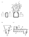
以下、図1の(イ)〜(ハ)により本発明の実施の形態を説明する。初めに、図1の(イ)に示されているように、供給装置としてケーキ貯留ホッパ1が適用され、そして圧送ポンプに往復型容積ポンプ20が適用された例について説明する。本実施の形態によるパイプ輸送装置は、ケーキ貯留ホッパ1、往復型容積ポンプ20、輸送パイプ25等から構成されている。脱水ケーキは、従来技術に関して説明したようにして得られ、そしてケーキ貯留ホッパ1に一時的に貯留され、流動化あるいは液状化される。そして、往復型容積ポンプ20に供給され、この往復型容積ポンプ20を駆動することにより流動化あるいは液状化された脱水ケーキは目的地、例えば焼却炉あるいは焼却炉に付随して設けられている貯留ビンまで輸送されるようになっている。
Hereinafter, an embodiment of the present invention will be described with reference to FIGS. First, as shown in FIG. 1A, an example in which the cake storage hopper 1 is applied as a supply device and the
ケーキ貯留ホッパ1は、従来周知の形態をしたホッパ2を備えている。ホッパ2の上部には、脱水ケーキ投入口3が設けられ、そして下方の開放端4は往復型容積ポンプ10の吸込口に接続されている。このように構成されているホッパ2の内部に、供給される脱水ケーキを粗粉砕する粉砕羽根としてのスクレーパ5、5が設けられている。また、流動化あるいは液状化するための剪断羽根として複数枚の羽根からなるチョッパ10が設けられている。スクレーパ6、6のアーム6、6は、ホッパ2の上部に回転自在に設けられている回転体7に取り付けられ、この回転体7がベルトとのような動力伝達手段8を介して電動モータあるいは油圧モータ9により、比較的低速で回転駆動されるようになっている。
The cake storage hopper 1 includes a
剪断羽根すなわちチョッパ10は、図1においては模式的に示されているが、その1枚の羽根は例えばプロペラ形状あるいは平羽根形状を呈している。そして、これらの羽根が所定の間隔をおいて回転軸11に複数段にわたって、回転に対してバランスするようにクロス状あるいは螺旋状に設けられている。このように構成されているチョッパ10は、図示の実施の形態では、ホッパ2の下方に位置している。回転軸11は、上方へ延び、変速機12の出力軸に接続され、電動モータあるいは油圧モータ13により比較的高速で回転駆動されるようになっている。
The shear blade or
汚泥のような粘性の高い脱水ケーキを圧送するための往復動型容積ポンプは、文献名を挙げるまでもなく従来周知であり、一般にシリンダとピストンとから構成され、ピストンの後退運動で、脱水ケーキはシリンダ内に吸引され、前進運動で吐出口から圧送されるようになっている。このような往復動型容積ポンプの復列型ポンプは、本出願人によって特願昭58−60662号によって提案されているので、詳しくは説明しないが、往復動複列型容積ポンプは、脱水ケーキを圧送するための一対の圧送用のピストン・シリンダユニットと、このユニットを交互に駆動する駆動用のピストン・シリンダユニットと、これらのユニットに対応して設けられている油圧回路を適宜切り換える方向切換弁とから概略構成されている。前述したように、往復動複列型容積ポンプは、従来周知であり、また本出願人の前記特許願にも開示されているので、図1の(イ)には模式的にシングルタイプの往復動型容積ポンプ20と、駆動用のピストン・シリンダユニット21とが示されている。
A reciprocating positive displacement pump for pumping a highly viscous dewatering cake such as sludge is well known in the art, not to mention the literature name, and is generally composed of a cylinder and a piston. Is sucked into the cylinder and is pumped from the discharge port by forward movement. Such a reciprocating pump of the reciprocating volume pump has been proposed by the present applicant in Japanese Patent Application No. 58-60662, and will not be described in detail. Direction switching for appropriately switching between a pair of pumping piston / cylinder units for pumping the piston, a driving piston / cylinder unit for alternately driving the units, and a hydraulic circuit provided corresponding to these units It is roughly composed of a valve. As described above, the reciprocating double-row type positive displacement pump is well known in the art and is also disclosed in the above-mentioned patent application of the present applicant. Therefore, in FIG. A
次に、上記実施の形態の作用について説明する。ホッパ2に脱水ケーキを供給する。そして、モータ4によりスクレーパ5、5を比較的低速で回転駆動する。また、チョッパ10はモータ13により高速で回転駆動する。そうすると、塊状で供給される脱水ケーキは、スクレーパ5、5により粗粉砕され、チョッパ10により剪断力が加えられ流動化する。あるいは液状になる。駆動用のピストン・シリンダユニット21に作動油を給排する。そうすると、前述したようにして流動化された脱水ケーキは圧送用の往復動型容積ポンプ20に吸い込まれ、そして輸送パイプ25中に吐出される。これにより、脱水ケーキは輸送パイプ25中を順次所定箇所へ圧送される。
Next, the operation of the above embodiment will be described. A dehydrated cake is supplied to the
本実施の形態によると、脱水ケーキは往復動型容積ポンプ20に供給する前に流動化あるいは液状化されているので、格別な押込装置がなくても、また往復動型容積ポンプ20のピストンの引き速度が早くても、シリンダに効率よく吸込まれ、ポンプのシリンダへの充填効率が低下するようなことはない。また、流動化あるいは液状化されているので、輸送パイプ25中での圧力損失抵抗も小さく、従来の技術の項で述べたような滑剤の注入も格別に必要としない。
According to the present embodiment, since the dewatered cake is fluidized or liquefied before being supplied to the reciprocating
供給装置の第2の実施の形態が、図1の(ロ)に示されている。本実施の形態によると、ホッパ2’と2個のチョッパ10’、10’とから構成されている。これらのチョッパ10’、10’は、いずれもホッパ2’の下方の側壁に取り付けられ、モータ13’により直接的に回転駆動されるようになっている。図1の(ロ)には、スクレーパは示されていないが、粉砕羽根としてスクレーパあるいは攪拌羽根を設けることもできる。本実施の形態も前述した実施の形態と略同じように作用することは明らかである。
A second embodiment of the supply device is shown in FIG. According to the present embodiment, the hopper 2 'and the two choppers 10' and 10 'are configured. These
図1の(ハ)に供給装置の第3の実施の形態が示されている。本実施の形態によると、水平方向に配置されたスクリュフィーダ30からなり、その上流側は図示されないホッパに接続され、下流側は下方に曲げられ、その先端部は前述したような往復型容積ポンプの吸込口に接続されるようになっている。このように構成されているスクリュフィーダ30の供給側と、排出側とにチョッパ10’、10’がそれぞれ設けられている。スクリュフィーダ30のスクリュ31を駆動するモータは示されていないが、このモータは例えばインバータ回路により回転数が制御され、往復型容積ポンプへの脱水ケーキの押込圧力を所定値に保つことができるようになっている。全体として第1、2の実施の形態と同様に作用することは明らかである。
A third embodiment of the supply device is shown in FIG. According to the present embodiment, the
本発明は、上記の実施の形態に限定されることなく、色々な形で実施できる。例えば、脱水ケーキの性質に応じてモータ4、13、13’の回転速度を変えるように実施できる。また、スクレーパおよびチョッパの数、配置位置も図示の実施の形態に限定されないことは明らかである。さらには、スクリュフィーダ30に代えてロータリフィーダで実施できることも明らかである。また、図1の(ロ)には、2個のチョッパ10’、10’が示されているが、1個でも実施できるし、他の攪拌羽根と組み合わせることもできる。図1の(ハ)に示されている実施の形態では、チョッパ10’は、スクリュフィーダ30の供給側と排出側とにそれぞれ設けられているが、少なくともいずれか一方に設けても同様な効果が得られることは明らかである。さらには、図1には示されていないが、圧送ポンプの吸込口に脱水ケーキ導入部材を設け、この導入部材の内部にチョッパ10’を設けることもできる。
The present invention is not limited to the above-described embodiment, and can be implemented in various forms. For example, the rotation speed of the
1 ケーキ貯留ホッパ1 2、2’ ホッパ
5 スクレーパ 10、10’ チョッパ
20 往復動型容積ポンプ 25 輸送パイプ
30 スクリュフィーダ
DESCRIPTION OF SYMBOLS 1 Cake storage hopper 1 2, 2 '
30 screw feeder
Claims (7)
脱水ケーキを、前記圧送ポンプに供給する前に、剪断羽根により流動化あるいは液状化処理して供給することを特徴とする脱水ケーキのパイプ輸送方法。 When supplying dewatered cake obtained by dewatering from sewage sludge, sewage sludge, etc. generated in a sewage treatment plant to a pump, and driving the pump to transport the pipe to a predetermined location,
A method for transporting a dehydrated cake by pipe, wherein the dehydrated cake is supplied after being fluidized or liquefied by a shear blade before being supplied to the pump.
脱水ケーキを、前記圧送ポンプに供給する前に、攪拌羽根で粗粉砕すると共に剪断羽根により流動化あるいは液状化処理して供給することを特徴とする脱水ケーキのパイプ輸送方法。 When supplying dewatered cake obtained by dewatering from sewage sludge, sewage sludge, etc. generated in a sewage treatment plant to a pump, and driving the pump to transport the pipe to a predetermined location,
A method for transporting a dehydrated cake by pipes, characterized in that the dehydrated cake is coarsely pulverized by a stirring blade and fluidized or liquefied by a shear blade before being supplied to the pump.
脱水ケーキを、前記供給装置を介して前記圧送ポンプに供給すると共に、前記圧送ポンプを駆動すると、脱水ケーキが前記輸送パイプを介して所定箇所へ圧送されるようになっているパイプ輸送装置であって、
前記供給装置には、脱水ケーキを流動化あるいは液状化処理する剪断羽根が設けられていることを特徴とする脱水ケーキのパイプ輸送装置。 A pressure pump, a supply device provided on the upstream side of the pressure pump, and a dehydrating cake for supplying the dehydrated cake to the pressure pump; and a transport pipe connected to the downstream side of the pressure pump,
A dewatering cake is supplied to the pumping pump via the supply device, and when the pumping pump is driven, the dewatering cake is pumped to a predetermined location via the transporting pipe. And
The dehydrating cake pipe transporting apparatus, wherein the feeding device is provided with shear blades for fluidizing or liquefying the dewatering cake.
Priority Applications (1)
| Application Number | Priority Date | Filing Date | Title |
|---|---|---|---|
| JP2005185985A JP4971600B2 (en) | 2005-06-27 | 2005-06-27 | Pipe transport method and transport device for dehydrated cake |
Applications Claiming Priority (1)
| Application Number | Priority Date | Filing Date | Title |
|---|---|---|---|
| JP2005185985A JP4971600B2 (en) | 2005-06-27 | 2005-06-27 | Pipe transport method and transport device for dehydrated cake |
Publications (2)
| Publication Number | Publication Date |
|---|---|
| JP2007000820A true JP2007000820A (en) | 2007-01-11 |
| JP4971600B2 JP4971600B2 (en) | 2012-07-11 |
Family
ID=37686897
Family Applications (1)
| Application Number | Title | Priority Date | Filing Date |
|---|---|---|---|
| JP2005185985A Active JP4971600B2 (en) | 2005-06-27 | 2005-06-27 | Pipe transport method and transport device for dehydrated cake |
Country Status (1)
| Country | Link |
|---|---|
| JP (1) | JP4971600B2 (en) |
Cited By (3)
| Publication number | Priority date | Publication date | Assignee | Title |
|---|---|---|---|---|
| JP2007050374A (en) * | 2005-08-19 | 2007-03-01 | Sumitomo Osaka Cement Co Ltd | Method for transporting sludge with low water content, transporting device therefor, and cement production equipment |
| JP2009297703A (en) * | 2008-05-13 | 2009-12-24 | Mitsubishi Heavy Industries Environment & Chemical Engineering Co Ltd | Method and apparatus for transporting organic dewatered sludge |
| CN109132391A (en) * | 2018-07-06 | 2019-01-04 | 安徽香草茶业有限公司 | A kind of tea raw material conveying device |
Citations (8)
| Publication number | Priority date | Publication date | Assignee | Title |
|---|---|---|---|---|
| JPS62196225A (en) * | 1986-02-20 | 1987-08-29 | Ube Ind Ltd | Delivering method for high concentration slury of coal and water from store tank |
| JPH07171547A (en) * | 1993-12-16 | 1995-07-11 | Chubu Electric Power Co Inc | Fermentation system for organic waste |
| JPH07290037A (en) * | 1994-04-22 | 1995-11-07 | Sumiyoshi Heavy Ind Co Ltd | Device for treating construction sludge |
| JPH07291445A (en) * | 1994-04-28 | 1995-11-07 | Taiheiyo Kiko Kk | Method and device for pipe transport of sludge and the like |
| JPH11342305A (en) * | 1998-06-02 | 1999-12-14 | Yokohama City | Sewage treatment equipment |
| JP2002146827A (en) * | 2000-11-07 | 2002-05-22 | Honmagumi:Kk | Mud treatment method and treatment device thereof |
| JP2002349426A (en) * | 2001-05-22 | 2002-12-04 | Ishigaki Co Ltd | Cake force feed pump |
| JP2005013845A (en) * | 2003-06-25 | 2005-01-20 | Sinto Brator Co Ltd | Scum disintegrator |
-
2005
- 2005-06-27 JP JP2005185985A patent/JP4971600B2/en active Active
Patent Citations (8)
| Publication number | Priority date | Publication date | Assignee | Title |
|---|---|---|---|---|
| JPS62196225A (en) * | 1986-02-20 | 1987-08-29 | Ube Ind Ltd | Delivering method for high concentration slury of coal and water from store tank |
| JPH07171547A (en) * | 1993-12-16 | 1995-07-11 | Chubu Electric Power Co Inc | Fermentation system for organic waste |
| JPH07290037A (en) * | 1994-04-22 | 1995-11-07 | Sumiyoshi Heavy Ind Co Ltd | Device for treating construction sludge |
| JPH07291445A (en) * | 1994-04-28 | 1995-11-07 | Taiheiyo Kiko Kk | Method and device for pipe transport of sludge and the like |
| JPH11342305A (en) * | 1998-06-02 | 1999-12-14 | Yokohama City | Sewage treatment equipment |
| JP2002146827A (en) * | 2000-11-07 | 2002-05-22 | Honmagumi:Kk | Mud treatment method and treatment device thereof |
| JP2002349426A (en) * | 2001-05-22 | 2002-12-04 | Ishigaki Co Ltd | Cake force feed pump |
| JP2005013845A (en) * | 2003-06-25 | 2005-01-20 | Sinto Brator Co Ltd | Scum disintegrator |
Cited By (3)
| Publication number | Priority date | Publication date | Assignee | Title |
|---|---|---|---|---|
| JP2007050374A (en) * | 2005-08-19 | 2007-03-01 | Sumitomo Osaka Cement Co Ltd | Method for transporting sludge with low water content, transporting device therefor, and cement production equipment |
| JP2009297703A (en) * | 2008-05-13 | 2009-12-24 | Mitsubishi Heavy Industries Environment & Chemical Engineering Co Ltd | Method and apparatus for transporting organic dewatered sludge |
| CN109132391A (en) * | 2018-07-06 | 2019-01-04 | 安徽香草茶业有限公司 | A kind of tea raw material conveying device |
Also Published As
| Publication number | Publication date |
|---|---|
| JP4971600B2 (en) | 2012-07-11 |
Similar Documents
| Publication | Publication Date | Title |
|---|---|---|
| US10717612B2 (en) | System for conveying pasty material | |
| CN204003439U (en) | The two screw pump of helical blade line with rubber on a kind of pump shaft | |
| JP4971600B2 (en) | Pipe transport method and transport device for dehydrated cake | |
| CN103612924B (en) | Buffer memory feed hopper | |
| CN207297345U (en) | Parallel huge discharge screw pump device | |
| JP4937216B2 (en) | Method and apparatus for transporting organic dewatered sludge | |
| CN104192514A (en) | High-dryness-degree material conveying device | |
| CN100462571C (en) | Dual-pump driven hydraulic station for horizontal spiral centrifuge complete set system | |
| CN203064685U (en) | Sealed screw conveyer dedicated to extractor | |
| CN106144284A (en) | Semi-dry sludge Storing and conveying method and apparatus | |
| CN101798051B (en) | Sludge receiving/storing/conveying system | |
| CN202401767U (en) | Pre-pressurization conveying device of high-pressure thick-body pumping device | |
| KR200453464Y1 (en) | Pump | |
| CN208057397U (en) | Double helix sump oil water recovery device | |
| JP5572333B2 (en) | Transport device | |
| CN207015663U (en) | A kind of feeding and conveying device for lazy flow material | |
| JP2004196478A (en) | Force feeding method of dewatered sludge, and the dewatered sludge for force feeding | |
| JP3809960B2 (en) | Pipe transportation method and equipment for sludge etc. | |
| CN204299865U (en) | A kind of energy-efficient chemical industry Special rotor pump | |
| JP6409244B2 (en) | Sludge transfer device | |
| CN102748279A (en) | Elliptic-rotating sliding vane pump | |
| CN201545772U (en) | Sludge receiving, storing and transporting system device | |
| JP6413146B2 (en) | Sludge transfer device | |
| JP2010248958A (en) | Transfer device of high viscosity material | |
| CN102530500A (en) | Vacuum screw-rod delivery pump |
Legal Events
| Date | Code | Title | Description |
|---|---|---|---|
| A621 | Written request for application examination |
Free format text: JAPANESE INTERMEDIATE CODE: A621 Effective date: 20080530 |
|
| A977 | Report on retrieval |
Free format text: JAPANESE INTERMEDIATE CODE: A971007 Effective date: 20090612 |
|
| A131 | Notification of reasons for refusal |
Free format text: JAPANESE INTERMEDIATE CODE: A131 Effective date: 20101207 |
|
| A521 | Request for written amendment filed |
Free format text: JAPANESE INTERMEDIATE CODE: A523 Effective date: 20110203 |
|
| RD03 | Notification of appointment of power of attorney |
Free format text: JAPANESE INTERMEDIATE CODE: A7423 Effective date: 20110203 |
|
| A131 | Notification of reasons for refusal |
Free format text: JAPANESE INTERMEDIATE CODE: A131 Effective date: 20110817 |
|
| TRDD | Decision of grant or rejection written | ||
| A01 | Written decision to grant a patent or to grant a registration (utility model) |
Free format text: JAPANESE INTERMEDIATE CODE: A01 Effective date: 20120403 |
|
| A01 | Written decision to grant a patent or to grant a registration (utility model) |
Free format text: JAPANESE INTERMEDIATE CODE: A01 |
|
| A61 | First payment of annual fees (during grant procedure) |
Free format text: JAPANESE INTERMEDIATE CODE: A61 Effective date: 20120406 |
|
| FPAY | Renewal fee payment (event date is renewal date of database) |
Free format text: PAYMENT UNTIL: 20150413 Year of fee payment: 3 |
|
| R150 | Certificate of patent or registration of utility model |
Ref document number: 4971600 Country of ref document: JP Free format text: JAPANESE INTERMEDIATE CODE: R150 Free format text: JAPANESE INTERMEDIATE CODE: R150 |
|
| R250 | Receipt of annual fees |
Free format text: JAPANESE INTERMEDIATE CODE: R250 |
|
| R250 | Receipt of annual fees |
Free format text: JAPANESE INTERMEDIATE CODE: R250 |
|
| R250 | Receipt of annual fees |
Free format text: JAPANESE INTERMEDIATE CODE: R250 |
|
| R250 | Receipt of annual fees |
Free format text: JAPANESE INTERMEDIATE CODE: R250 |
|
| R250 | Receipt of annual fees |
Free format text: JAPANESE INTERMEDIATE CODE: R250 |
|
| R250 | Receipt of annual fees |
Free format text: JAPANESE INTERMEDIATE CODE: R250 |
|
| R250 | Receipt of annual fees |
Free format text: JAPANESE INTERMEDIATE CODE: R250 |
|
| R250 | Receipt of annual fees |
Free format text: JAPANESE INTERMEDIATE CODE: R250 |