JP2006525099A - Device, system and method for bioimpedance measurement of cervical tissue and method for diagnosis and treatment of human cervix - Google Patents
Device, system and method for bioimpedance measurement of cervical tissue and method for diagnosis and treatment of human cervix Download PDFInfo
- Publication number
- JP2006525099A JP2006525099A JP2006514248A JP2006514248A JP2006525099A JP 2006525099 A JP2006525099 A JP 2006525099A JP 2006514248 A JP2006514248 A JP 2006514248A JP 2006514248 A JP2006514248 A JP 2006514248A JP 2006525099 A JP2006525099 A JP 2006525099A
- Authority
- JP
- Japan
- Prior art keywords
- electrodes
- tissue
- electrode
- voltage
- array
- Prior art date
- Legal status (The legal status is an assumption and is not a legal conclusion. Google has not performed a legal analysis and makes no representation as to the accuracy of the status listed.)
- Pending
Links
Images


Classifications
-
- A—HUMAN NECESSITIES
- A61—MEDICAL OR VETERINARY SCIENCE; HYGIENE
- A61B—DIAGNOSIS; SURGERY; IDENTIFICATION
- A61B17/00—Surgical instruments, devices or methods, e.g. tourniquets
- A61B17/42—Gynaecological or obstetrical instruments or methods
-
- A—HUMAN NECESSITIES
- A61—MEDICAL OR VETERINARY SCIENCE; HYGIENE
- A61B—DIAGNOSIS; SURGERY; IDENTIFICATION
- A61B5/00—Measuring for diagnostic purposes; Identification of persons
- A61B5/05—Detecting, measuring or recording for diagnosis by means of electric currents or magnetic fields; Measuring using microwaves or radio waves
- A61B5/053—Measuring electrical impedance or conductance of a portion of the body
- A61B5/0538—Measuring electrical impedance or conductance of a portion of the body invasively, e.g. using a catheter
-
- A—HUMAN NECESSITIES
- A61—MEDICAL OR VETERINARY SCIENCE; HYGIENE
- A61B—DIAGNOSIS; SURGERY; IDENTIFICATION
- A61B5/00—Measuring for diagnostic purposes; Identification of persons
- A61B5/43—Detecting, measuring or recording for evaluating the reproductive systems
- A61B5/4306—Detecting, measuring or recording for evaluating the reproductive systems for evaluating the female reproductive systems, e.g. gynaecological evaluations
- A61B5/4318—Evaluation of the lower reproductive system
- A61B5/4331—Evaluation of the lower reproductive system of the cervix
-
- A—HUMAN NECESSITIES
- A61—MEDICAL OR VETERINARY SCIENCE; HYGIENE
- A61B—DIAGNOSIS; SURGERY; IDENTIFICATION
- A61B5/00—Measuring for diagnostic purposes; Identification of persons
- A61B5/68—Arrangements of detecting, measuring or recording means, e.g. sensors, in relation to patient
- A61B5/6846—Arrangements of detecting, measuring or recording means, e.g. sensors, in relation to patient specially adapted to be brought in contact with an internal body part, i.e. invasive
- A61B5/6885—Monitoring or controlling sensor contact pressure
-
- A—HUMAN NECESSITIES
- A61—MEDICAL OR VETERINARY SCIENCE; HYGIENE
- A61B—DIAGNOSIS; SURGERY; IDENTIFICATION
- A61B17/00—Surgical instruments, devices or methods, e.g. tourniquets
- A61B2017/00017—Electrical control of surgical instruments
- A61B2017/00022—Sensing or detecting at the treatment site
- A61B2017/00026—Conductivity or impedance, e.g. of tissue
Landscapes
- Health & Medical Sciences (AREA)
- Life Sciences & Earth Sciences (AREA)
- Surgery (AREA)
- Medical Informatics (AREA)
- Animal Behavior & Ethology (AREA)
- Veterinary Medicine (AREA)
- Public Health (AREA)
- Engineering & Computer Science (AREA)
- Biomedical Technology (AREA)
- Heart & Thoracic Surgery (AREA)
- General Health & Medical Sciences (AREA)
- Molecular Biology (AREA)
- Physics & Mathematics (AREA)
- Biophysics (AREA)
- Pathology (AREA)
- Nuclear Medicine, Radiotherapy & Molecular Imaging (AREA)
- Gynecology & Obstetrics (AREA)
- Reproductive Health (AREA)
- Radiology & Medical Imaging (AREA)
- Pregnancy & Childbirth (AREA)
- Measurement And Recording Of Electrical Phenomena And Electrical Characteristics Of The Living Body (AREA)
- Investigating Or Analysing Biological Materials (AREA)
- Measuring Or Testing Involving Enzymes Or Micro-Organisms (AREA)
Abstract
特徴とするのは、子宮頚部の組織、より具体的には哺乳類の子宮頚部の組織の、バイオインピーダンスを測定するための装置(220)である。さらに特徴とするのは、臨床および診断目的のために子宮頚部組織を試験する方法であって、例えばルーチンの婦人科検査において、妊娠中の患者の陣痛の早期開始を決定するため、または妊婦および妊娠していない女性の両方において癌病変などの異常の存在についてかかる組織を評価するためなどである。さらに特徴とするのは、かかるデバイス、装置(220)および/または方法を取り入れた、初期または早期陣痛の開始を処置するための方法であって、ここでかかるシステムは、妊娠中および妊娠していない患者を診断および/または検査する際に、診断医または臨床医をさらに支援するための診断/臨床情報を提供するように構成するのが好ましい。Characterized by a device (220) for measuring the bioimpedance of cervical tissue, more specifically mammalian cervical tissue. Further characterized is a method of testing cervical tissue for clinical and diagnostic purposes, such as in routine gynecological examinations, to determine early onset of labor in pregnant patients, or For example, to evaluate such tissues for the presence of abnormalities such as cancerous lesions in both women who are not pregnant. Further characterized is a method for treating the onset of early or early labor that incorporates such a device, apparatus (220) and / or method, wherein such a system is pregnant and pregnant. Preferably, it is configured to provide diagnostic / clinical information to further assist the diagnostician or clinician in diagnosing and / or examining non-patients.
Description
本発明は、2003年5月2日出願の米国仮出願第60/467,456号および2003年8月22日出願の米国仮出願第60/497,300号の利益を主張し、これらの教示の全ては参照として本明細書に組み込まれる。 The present invention claims the benefit of US Provisional Application No. 60 / 467,456, filed May 2, 2003, and US Provisional Application No. 60 / 497,300, filed August 22, 2003, all of which are incorporated by reference. As incorporated herein.
技術分野
本発明は、バイオインピーダンス、より具体的にはヒト子宮頚部組織のバイオインピーダンス測定のためのデバイス、システムおよび方法に関し、そして本発明はまた、かかる測定方法を、組織および/または器官の、より具体的にはヒト子宮頚部およびヒト子宮頚部組織の診断、検査および処置のために具体化する方法に関する。
TECHNICAL FIELD The present invention relates to bioimpedance, more specifically to devices, systems and methods for bioimpedance measurement of human cervical tissue, and the present invention also relates to such measurement methods for tissues and / or organs. More specifically, it relates to a method embodied for diagnosis, examination and treatment of human cervix and human cervical tissue.
背景技術
早期陣痛または早産は、毎年何十億ドルもの医療費が費やされる重要な問題である。新生児は妊娠37週未満で生まれた場合に早産と考えられる。米国における毎年の推定妊娠数6,250,000件のうち、約11%は早産である。Obstetrics - Normal and Problem Pregnancies, 4th ed., Copyright 2002 Churchill Livingstone, Inc. P.755-763; http://www.wvdhr.org/bph/hp2010/objective/16.htm、2003年5月14日。生殖技術の使用、35歳を上回る年齢の女性の妊娠数の増加、および多胎妊娠の発生の増加は、潜在的にこの数字の将来の増加を導き得る。さらに、早産の約80%は自然に生じるもので、一方その残りは、胎児または母親に認められる合併症への反応として誘発される。Mattison, D.R. et al., Pre-term Delivery: a public health perspective, Paediatric and Perinatal Epidemiology 2001, 15 (Supple. 2), 7-16。
Background Art Preterm labor or premature birth is an important issue that costs billions of dollars in health care annually. Newborns are considered premature if they are born in less than 37 weeks of gestation. Of the estimated 62,500,000 annual pregnancies in the United States, approximately 11% are preterm. Obstetrics-Normal and Problem Pregnancies, 4 th ed., Copyright 2002 Churchill Livingstone, Inc. P.755-763; http://www.wvdhr.org/bph/hp2010/objective/16.htm, May 14, 2003 Day. The use of reproductive techniques, the increase in the number of pregnancies in women older than 35 years, and the increase in the incidence of multiple pregnancies can potentially lead to future increases in this number. In addition, about 80% of preterm births occur naturally, while the rest are triggered as a response to complications found in the fetus or mother. Mattison, DR et al., Pre-term Delivery: a public health perspective, Paediatric and Perinatal Epidemiology 2001, 15 (Supple. 2), 7-16.
早期に生まれた新生児は、正常期間で生まれた新生児より生理的にかなり発達が遅れている。その結果、図1A、1Bに示すように、非常に高い新生児急性罹患率および死亡率が、かかる新生児、特に非常に早期(例えば23〜27週)に生まれた新生児と関連する。これらの早産児はまた、満期出産児より高いリスクの長期健康問題に直面する。このような健康問題には、呼吸器系の発育不良、神経系への合併症、栄養摂取の問題、精神遅滞、および脳室内(脳)出血などが含まれる。Confronting Pre-term Delivery in the 21st Century: From Molecular Intervention to Community Action http:/www.medscape.com/viewaarticle/408935。重篤な出生前合併症または死亡の約60%が、早期の分娩のために起こる。さらに早産はまた、膜の早期破裂(PROM)による感染および産後抑うつ症を含む、妊婦の幾つかの合併症に関連する。妊婦のリスクの最も重要な源は、帝王切開による分娩の高い割合と関連する。未熟分娩(早産)は必要とされる外科手術のレベルを困難化し、出血、血栓塞栓症および感染の可能性を高める。 Newborns born early are more physiologically delayed in development than newborns born in normal periods. As a result, as shown in FIGS. 1A and 1B, very high neonatal acute morbidity and mortality are associated with such neonates, particularly those born very early (eg, 23-27 weeks). These preterm infants also face higher risk long-term health problems than full-term infants. Such health problems include poor respiratory development, nervous system complications, nutritional problems, mental retardation, and intraventricular (brain) bleeding. Confronting Pre-term Delivery in the 21 st Century: From Molecular Intervention to Community Action http: /www.medscape.com/viewaarticle/408935. About 60% of serious prenatal complications or deaths occur due to premature labor. In addition, preterm birth is also associated with several complications in pregnant women, including premature membrane rupture (PROM) infection and postpartum depression. The most important source of maternal risk is associated with a high proportion of cesarean deliveries. Premature labor (premature labor) complicates the level of surgery required and increases the likelihood of bleeding, thromboembolism and infection.
早産は医療リスクを高めるだけでなく、医療コストも増加させ、ここで主な医療コストは一般に分娩後にかかる。これらの早産児は通常、満期出産児よりも、非常に長い入院期間(例えば、早産児の平均入院期間は21.7日)およびより高額の処置が必要となる。かかる処置には、インキュベーション、呼吸補助、および透析が含まれる。早産児のケアのためのコストは年に60億ドルを超え、このコストの約75%は、人生の1年目に、ほとんどが最初の入院において消費されることが報告されている。かかる支出の定量化はまた、生存新生児当たりの平均コストと在胎期間の間の逆相関を示している。例としては、正常な妊娠は平均6,400ドルの費用がかかるが、早産児に関連する医療費は2万ドル〜100万ドルにも上り、妊娠26〜28週で生まれた新生児1人当たりの平均費用は約49,000ドルである。 Preterm birth not only increases medical risk, but also increases medical costs, where the main medical costs are generally incurred after delivery. These premature infants usually require a much longer hospital stay (eg, an average hospital stay of 21.7 days for preterm infants) and higher treatment than full-term infants. Such treatments include incubation, respiratory assistance, and dialysis. Costs for the care of premature infants exceed $ 6 billion a year, and it is reported that about 75% of this cost is mostly consumed in the first hospitalization in the first year of life. Such quantification of expenditure also shows an inverse correlation between average cost per surviving neonate and gestational age. As an example, a normal pregnancy costs an average of $ 6,400, but the medical costs associated with preterm infants can be as high as $ 20,000 to $ 1 million, per newborn born between 26 and 28 weeks of gestation The average cost is about $ 49,000.
早産を引き起こし得る多数の条件が存在する。これらには、遺伝的素因、妊婦または胎児のストレスまたは感染、羊膜の早期破裂、異常なホルモン信号、および異常な子宮の特性などが含まれる。原因に関わらず、妊娠中の子宮頚部の軟化、拡張および展退並びに陣痛は、子宮収縮のみの結果として起こるのではなく、子宮頚部の構造の能動的なリモデリングの結果でもある。早期陣痛はしばしば、子宮頚部のリモデリングの引き金となる正常な信号の不適切なタイミングの結果起こり、子宮頚部組織の早期の軟化は、自然流産、早期分娩を引き起こし、そして時には正常な経膣分娩を損なう可能性がある。 There are a number of conditions that can cause preterm birth. These include genetic predisposition, maternal or fetal stress or infection, premature amniotic rupture, abnormal hormonal signals, and abnormal uterine characteristics. Regardless of the cause, cervical softening, dilatation and extension and labor during pregnancy are not the result of uterine contractions alone, but are also the result of active remodeling of the cervical structure. Early labor often results from improper timing of normal signals that trigger cervical remodeling, and early softening of cervical tissue causes spontaneous miscarriage, premature labor, and sometimes normal vaginal labor May be damaged.
リモデリングのためのホルモン信号が到達する妊娠中の時期に関わらず、それらの信号は子宮頚部における同様の変化の引き金になると考えられている。陣痛への移行の際、ヒト妊娠子宮頚部の組織は大きなリモデリングを受けて、その主要なコラーゲン基質がグリコサミノグリカンによって置き換えられる。この「成熟」の結果子宮頚部が軟化し、これによって、胎児が子宮から出ることを可能にするために最終的に必要とされる薄化および拡張に備える。 Regardless of the time of pregnancy when hormonal signals for remodeling arrive, they are thought to trigger similar changes in the cervix. Upon transition to labor, the human cervical tissue undergoes major remodeling, and its major collagen matrix is replaced by glycosaminoglycans. This “maturation” results in softening of the cervix, thereby preparing for the thinning and expansion ultimately required to allow the fetus to leave the uterus.
もしも十分早期に検知されたならば、許容し得る在胎期間までおよび胎児が発達するまで陣痛を遅延させるのに非常に効果的な、幾つかの処置が存在する。これらの処置は、床上安静のように簡単なものから、陣痛を遅延させるか、その進行を阻むために投与可能な薬剤まで、多岐に渡っている。かかる薬剤は、限定はされないが、βアドレナリン作動性受容体作動薬、硫酸マグネシウム、カルシウムチャネル遮断薬、シクロオキシゲナーゼ阻害薬、サルブマトール、リドカインおよび酸化窒素/酸化窒素供与体を含む。コルチコステロイドもまた、未成熟な胎児に対する具体的な処置として、器官の成熟を増強するため、また肺の発達を早めることによって胎児の肺機能を改善するため、また酸素交換に必要な呼吸酵素として、頻繁に用いられる。これらはまた脳室内出血および消化管の障害のリスクを減少させることができる。これらの処置は、早期陣痛の開始を妊娠期間の初期においてとらえることができれば、より効果的で安全となり得る。 If detected early enough, there are several treatments that are very effective in delaying labor until the acceptable gestational period and until the fetus develops. These treatments range from as simple as resting on the floor to drugs that can be administered to delay labor or prevent its progression. Such agents include, but are not limited to, beta-adrenergic receptor agonists, magnesium sulfate, calcium channel blockers, cyclooxygenase inhibitors, salbumatol, lidocaine and nitric oxide / nitric oxide donors. Corticosteroids are also a specific treatment for immature fetuses, to enhance organ maturation, to improve fetal lung function by accelerating lung development, and to the respiratory enzymes required for oxygen exchange As frequently used. They can also reduce the risk of intraventricular hemorrhage and gastrointestinal disorders. These treatments can be more effective and safer if the onset of early labor can be caught early in pregnancy.
早期陣痛の早期の正確な診断は主要な問題であるが、これは、早期陣痛であると診断された患者の約50%までが実際には早期陣痛がなく、しかし、陣痛ではないと診断された症状のある患者の20%までもが、早期に分娩するからである。かかる誤診は問題であり、なぜならば、本明細書に示すように、妊娠期間の早期における介入は、早期分娩を効果的に予防するのにより有利だからである。現在医師は、患者の履歴、生化学的検査結果、および子宮頚部の検査などの幾つかのパラメータの重要性を、早期陣痛の開始を予測するために重視する。例えば、一定の産科学的状態に関する重要な患者の履歴、例えば子宮頚部不全症、羊水の感染、以前の流産または以前の早期分娩などは、指標または続く妊娠において早期陣痛のリスクを増加させることが示されている。 Early and accurate diagnosis of early labor is a major problem, but it is estimated that up to about 50% of patients diagnosed with early labor actually have no early labor but are not diagnosed with labor. This is because up to 20% of symptomatic patients deliver early. Such misdiagnosis is a problem because, as shown herein, intervention early in pregnancy is more advantageous in effectively preventing preterm labor. Currently, physicians value the importance of several parameters such as patient history, biochemical test results, and cervical examinations to predict the onset of early labor. For example, important patient histories for certain obstetric conditions such as cervical insufficiency, amniotic fluid infection, previous miscarriage or previous preterm delivery may increase the risk of early labor in the indicator or subsequent pregnancy. It is shown.
陣痛を予測する最も信頼できる方法は、産科医が子宮頚部を指で触診して(彼/彼女の指を用いて)、その軟らかさを調べることである。かかる検査は、子宮頚部の潤軟度(consistency)、位置、拡張および展退における進行性の変化の有無について、1〜2時間の間隔で、産科医が確信できるまで行われる。この方法は産科医の経験に依存するのみでなく、本質的に定性的であり、従って変化が感じられるためには、子宮頚部潤軟度に大きな変化が生じることが必要である。産科医はまた、超音波技術を用いて胎児の位置および子宮頚部の長さを測定できるが、このデータのみでは、分娩が起こるかどうかを予測するには不十分である。 The most reliable way to predict labor is for the obstetrician to palpate the cervix with his finger (using his / her finger) and examine its softness. Such tests are performed at 1-2 hour intervals until the obstetrician can be confident of the presence or absence of progressive changes in cervical consistency, position, dilation and retraction. This method is not only dependent on obstetrician experience, but is qualitative in nature, so that a change in cervical softness needs to occur in order for changes to be felt. Obstetricians can also measure fetal position and cervical length using ultrasound techniques, but this data alone is not sufficient to predict whether labor will occur.
現在、許容し得る程度の感度および特異性を有する診断方法が欠如しているため、研究者らに対して、早期陣痛を早期に予測する他の方法の探索が促された。これらの方法の多くは、生化学的方法に対して、妊婦の子宮頚部に生じることが発見された物理的変化を定性的に測定することに基づく。経腹壁的筋電図法(EMG)および経膣超音波(TVS)を含む、より進んだ診断方法も存在し、診断の正確さを僅かに増加させることが示された。子宮頚部長さおよび筋収縮の強さは、TVSおよび経腹壁的EMGによっていかにして物理的変化を計測するかの例である。TVSは、超音波共鳴を用いて子宮頚部長さを測定し、これは子宮頚部不全(cervical incompetence)を反映することができる。残念ながらこの方法は、判定に用いるための標準的な子宮頚部測定値の欠如に関連する不確かさおよび、膀胱の充満のために子宮頚部長さが変化することを含む、多数の欠点を有している。早期陣痛を検知するために用いられる他の技術は、子宮収縮により生成される電圧を測定することを本質的に含む、経腹壁的EMGである。この技法の使用に関連する主要な欠点は、出産に特異的な子宮収縮は、実際の分娩時に比較的近い時点で起こる傾向があることである(例えば、約4日前)。これは実際問題として、母親に大きな効果を及ぼす予防処置に対してはあまりにも短すぎる。 Currently, the lack of diagnostic methods with acceptable sensitivity and specificity has prompted researchers to search for other methods to predict early labor early. Many of these methods are based on qualitative measurement of physical changes found to occur in the cervix of pregnant women, as opposed to biochemical methods. There are also more advanced diagnostic methods, including transabdominal electromyography (EMG) and transvaginal ultrasound (TVS), which have been shown to slightly increase the accuracy of the diagnosis. Cervical length and strength of muscle contraction are examples of how physical changes are measured by TVS and transabdominal EMG. TVS measures cervical length using ultrasound resonance, which can reflect cervical incompetence. Unfortunately, this method has a number of drawbacks, including the uncertainty associated with the lack of standard cervical measurements to use in the determination and cervical length changes due to bladder filling. ing. Another technique used to detect preterm labor is transabdominal EMG, which essentially involves measuring the voltage generated by uterine contractions. A major drawback associated with the use of this technique is that birth-specific uterine contractions tend to occur relatively close to the time of actual delivery (eg, about 4 days ago). This is in fact too short for preventive measures that have a great effect on the mother.
上記に関わらず、認識すべきであるのは、新生児のケアに関するおよそ20年間の改善にもかかわらず、この20年間早産の割合は減少せず、基本的に年間約11%のままで留まっていることである。これについては多くの理由があるが、本明細書に引用された重要な問題点は、早期陣痛の開始が臨床的に認められた時には、このプロセスを引き止めるためにできることは殆どないということである。従って、従来技法によって臨床的に明らかとなる前に、早期陣痛の開始を検知できることが望ましい。これにより、現在可能な時期より早期の妊娠期間において医学的介入を行うことが可能となり、かかる医学的介入が早期分娩を遅延または予防するのに成功する可能性を、現在の技法を用いて可能なことに比べてより高めることができる。 Regardless of the above, it should be recognized that despite the approximately 20 years improvement in neonatal care, the proportion of premature births in the last 20 years has not decreased, and basically remains at about 11% per year. It is that you are. There are many reasons for this, but the key issue cited here is that there is little that can be done to stop this process when clinical onset of early labor is recognized. . Therefore, it is desirable to be able to detect the onset of early labor before it becomes clinically apparent by conventional techniques. This allows medical interventions to be performed during gestation earlier than is currently possible, and the potential for such medical interventions to succeed in delaying or preventing preterm delivery using current techniques It can be higher than anything.
最近、多くの研究の焦点が、生化学的マーカーを早期陣痛の指標として用いることに向けられている。母親の血清または膣液/分泌物中の胎児性フィブロネクチン、胎盤のタンパク質、プロラクチンおよびエストリオールなどの化合物の一定の濃度は、早期分娩のリスクを示唆する。これらの方法はまだ実験段階にすぎず、特定の患者が実際に早期に分娩するかどうかを、任意の確実性をもって示唆することはできない。 Recently, much research focus has been devoted to using biochemical markers as indicators of early labor. Certain concentrations of compounds such as fetal fibronectin, placental protein, prolactin and estriol in maternal serum or vaginal fluid / secretory suggest a risk of preterm labor. These methods are only experimental and cannot suggest with certain certainty whether a particular patient will actually deliver early.
早期陣痛の早期検知に加えて、子宮頚部のリモデリングの度合いを評価することも望まれており、これは一般に、子宮頚部が陣痛に対して準備できているかまたは成熟しているかを決定するのに用いることができる。この決定は、合併症を伴う妊娠において、必要性が生じた場合に陣痛を誘発する方法を選択するための重要な意味を有する。さらに、コストの抑制の必要な現在において、陣痛の開始を正確に予測できるメカニズムを有することは、正常期間の妊娠に対しても有利である。これにより出産予定数がより正確に予測できるため、病院の陣痛および分娩ユニットのよりよい計画およびスタッフ配置が可能となる。 In addition to early detection of early labor, it is also desirable to assess the degree of cervical remodeling, which generally determines whether the cervix is ready or mature for labor. Can be used. This decision has important implications for selecting a method of inducing labor in the event of a need in complications of pregnancy. In addition, having a mechanism that can accurately predict the onset of labor at the present time when cost control is needed is also advantageous for normal-term pregnancy. This allows more accurate prediction of the expected number of births, thus allowing better planning and staffing of hospital labor and delivery units.
非産科的適用としては、組織、より具体的には子宮頚部組織の電気インピーダンススペクトルは、子宮頚部前癌状態の検知のためのスクリーニング技術として、より具体的には正常組織と前癌組織を正確に分離できるスクリーニング技術として、用いることが示唆された。Brown et al., Relation between tissue structure and imposed electrical current flow in certain neoplasia, Lancet 2000, 335:892-895。記載された技術においては、4個のフラッシュ搭載金電極を有するペンシルプローブ(すなわち、フラッシュはプローブのフェイスに搭載)が、子宮頚部上の8点からの電気インピーダンススペクトルを測定するのに用いられた。しかし、報告の方法および装置は概念の有効性を決定するために開発されたものであり、従って一般に実験目的であった。 For non-obstetric applications, the electrical impedance spectrum of tissue, more specifically cervical tissue, is a screening technique for detecting cervical precancerous conditions, more specifically normal tissue and precancerous tissue. It was suggested that it be used as a screening technique that can be separated. Brown et al., Relation between tissue structure and imposed electrical current flow in certain neoplasia, Lancet 2000, 335: 892-895. In the described technique, a pencil probe with four flash mounted gold electrodes (ie the flash mounted on the probe face) was used to measure the electrical impedance spectrum from 8 points on the cervix. . However, the reporting methods and apparatus were developed to determine the effectiveness of the concept and were therefore generally experimental purposes.
妊娠子宮頚部および、妊娠していない子宮頚部の、電気インピーダンス測定を用いた比較研究も報告された。O’Connel, MP; et al; An in vivo comparative study of the pregnant and non-pregnant cervix using bioelectrical impedance measurements, British Journal of Obstetrics and Gynecology, Aug. 2000, Vol. 107, P.1040-1041。この文献は、電気インピーダンス技法を、陣痛に先立つ子宮頚部の水和反応(hydration)における変化を特徴付けるのに用いることができると主張している。この文献はまた、満期および早期での陣痛開始の予測において臨床的価値を有し得ることも主張している。 A comparative study using electrical impedance measurements of pregnant and non-pregnant cervix was also reported. O'Connel, MP; et al; An in vivo comparative study of the pregnant and non-pregnant cervix using bioelectrical impedance measurements, British Journal of Obstetrics and Gynecology, Aug. 2000, Vol. 107, P.1040-1041. This document claims that electrical impedance techniques can be used to characterize changes in cervical hydration prior to labor. The document also claims that it may have clinical value in predicting onset of labor and maturity at an early stage.
記載された技術において、4個のフラッシュ搭載金電極を有するペンシルプローブ(すなわち、フラッシュはプローブのフェイスに搭載)が、子宮頚部の電気インピーダンススペクトルを測定するのに用いられた。この研究によれば、他の介入に先立つ陣痛の誘発時の分娩室の妊婦の子宮頚部の組織と、妊娠していない女性の子宮頚部の組織との間に抵抗値の差が観察された。しかし、報告された方法および装置は、妊娠後期の女性と妊娠していない女性の子宮頚部組織で測定された電気インピーダンスの間に顕著な違いがあるという、一般的な概念の有効性を決定するために開発された。記載され主張された他の臨床的使用に関しては、文献ではただ、電気インピーダンスはかかる使用に利用可能であるかもしれないと、主張または示唆するのみであり、バイオインピーダンス測定技法を、他の示唆または記述された臨床的使用に用いることの実証または開示は、含まれていない。 In the described technique, a pencil probe with four flash mounted gold electrodes (ie, the flash mounted on the probe face) was used to measure the electrical impedance spectrum of the cervix. According to this study, a difference in resistance was observed between the cervical tissue of pregnant women in the delivery room and the cervical tissue of non-pregnant women at the induction of labor prior to other interventions. However, the reported methods and devices determine the effectiveness of the general concept that there is a significant difference between the electrical impedances measured in cervical tissue of late-gestation women and non-pregnant women. Developed for. For other clinical uses that have been described and claimed, the literature merely claims or suggests that electrical impedance may be available for such use, and the bioimpedance measurement technique has other suggestions or No demonstration or disclosure for use in the described clinical use is included.
従って、臨床医または産科医が直接、患者の子宮頚部組織の電気インピーダンスを測定することができ、それによって臨床医が、産科的または非産科的診断/検査のために子宮頚部組織を評価できる、非侵襲的なデバイス、装置、システムおよび方法を提供することが望まれる。従来技術のデバイスおよび/または技法に比べて、臨床医による、妊娠早期の早期陣痛の開始の決定を可能にする、かかるデバイス、装置、システムおよび方法を提供することは特に望ましい。また、測定値を評価することにより、さらなる臨床情報(例えば、正常状態から逸脱したことの示唆)がシステムによって提供され、それによって、与えられた患者の検査または診断を行う臨床医/診断医を支援するような、かかるデバイスおよび装置を取り入れたシステムを提供することも望ましい。かかるデバイス、装置およびシステムは、構造が単純で、臨床医、診断医、または産科医が容易に用いることができるのが好ましい。かかるデバイス、装置および方法はまた、未熟児の新生児死亡率のリスクを低下させる有益な効果を有し、早産児に必要とされる医療処置のリスクおよび/または量を低減し、妊婦のリスクも低下させる。かかるデバイス、装置および方法はまた、特に、従来の産科的技法を子宮頚部組織の評価に用いる場合に起こることと比較して誤診を低減し、および/または早期分娩開始のリスクを低下させるという有益な効果を有するのが好ましい。かかるデバイス、装置、システムおよび方法はまた、非産科的目的で子宮頚部組織を評価するために既存の技法および方法と組み合わせて用いるのに容易に適合可能であるのが好ましく、これによって、子宮頚部組織の評価に侵襲的技法を用いる必要性を低減させる(例えば、子宮頚部生検を減らす)。 Thus, the clinician or obstetrician can directly measure the electrical impedance of the patient's cervical tissue, which allows the clinician to evaluate the cervical tissue for obstetrical or non-obstetric diagnosis / examination, It would be desirable to provide non-invasive devices, apparatuses, systems and methods. It is particularly desirable to provide such devices, apparatus, systems and methods that allow a clinician to determine the onset of early labor early in pregnancy compared to prior art devices and / or techniques. Also, by evaluating the measurements, additional clinical information (eg, an indication of deviation from normal conditions) is provided by the system, thereby allowing the clinician / diagnostician to examine or diagnose a given patient. It would also be desirable to provide a system incorporating such devices and apparatus that would assist. Such devices, apparatus and systems are preferably simple in structure and can be readily used by clinicians, diagnosticians or obstetricians. Such devices, apparatus and methods also have the beneficial effect of reducing the risk of neonatal mortality in premature infants, reducing the risk and / or amount of medical procedures required for preterm infants, and reducing the risk of pregnant women. Reduce. Such devices, apparatus and methods are also particularly beneficial in reducing misdiagnosis and / or reducing the risk of initiating premature labor compared to what occurs when conventional obstetric techniques are used to assess cervical tissue. It is preferable to have an advantageous effect. Such devices, apparatus, systems and methods are also preferably easily adaptable for use in combination with existing techniques and methods for assessing cervical tissue for non-obstetric purposes, whereby cervical Reduce the need to use invasive techniques for tissue assessment (eg, reduce cervical biopsy).
発明の概要
本発明は、子宮頚部、より具体的には哺乳類の子宮頚部組織の、バイオインピーダンスを測定するデバイスおよび装置を特徴とする。さらに特徴とするのはそれらに関連する方法、より具体的には臨床または診断目的で子宮頚部組織を検査するための方法であって、前記目的とは例えば、ルーチンの婦人科診査において妊娠中の患者の陣痛の早期開始を決定するため、または妊娠中および妊娠していない女性の両方における癌病変などの異常の存在について、かかる組織を評価するためなどである。さらに特徴とするのは、初期または早期の陣痛または分娩の開始を処置するための方法であり、これらの方法は、本発明のかかるデバイス、装置および方法を取り入れたものである。さらに特徴とするのは、本発明のかかるデバイス、装置および/または方法を取り入れたシステムである。かかるシステムは、妊娠中および妊娠していない患者の診断および/または検査において、診断医または臨床医をさらに支援する診断および/または臨床情報を提供するよう、構成および配置されるのが好ましい。かかる診断および/または臨床情報は、本発明のかかるデバイスおよび装置を用いて得たバイオインピーダンス測定値に基づき生成され、より具体的な態様においては、試験する子宮頚部組織の多数の可能な状態のうちの任意の1つを表す構築されたデータセットと測定値を比較することに基づき、生成される。かかるデバイス、装置、システムおよび方法、並びにそれらの態様および側面は、本明細書で考察および記述される。
SUMMARY OF THE INVENTION The present invention features devices and apparatus for measuring bioimpedance of the cervix, and more specifically, mammalian cervical tissue. Further characterized is a method associated therewith, more specifically, a method for examining cervical tissue for clinical or diagnostic purposes, such as during pregnancy during routine gynecological examinations. For example, to determine early onset of patient labor, or to evaluate such tissues for the presence of abnormalities such as cancerous lesions in both pregnant and non-pregnant women. Further featured are methods for treating early or early labor or onset of labor, which incorporate such devices, apparatus and methods of the present invention. Further characterized is a system incorporating such a device, apparatus and / or method of the present invention. Such a system is preferably configured and arranged to provide diagnostic and / or clinical information that further assists the diagnostician or clinician in the diagnosis and / or examination of pregnant and non-pregnant patients. Such diagnostic and / or clinical information is generated based on bioimpedance measurements obtained using such devices and apparatus of the present invention, and in a more specific aspect, a number of possible states of the cervical tissue being tested. Generated based on comparing measurements with a constructed data set representing any one of them. Such devices, apparatus, systems and methods, as well as embodiments and aspects thereof, are discussed and described herein.
その最も広い側面において、本発明のバイオインピーダンス測定装置は、バイオインピーダンス測定デバイスおよび、該バイオインピーダンス測定デバイスに操作可能に接続された信号発生/検出デバイスを含む。バイオインピーダンス測定デバイスは先端部材を含み、該先端部材は複数の電極を含むよう構成および配置されており、該電極それぞれの少なくとも端部は、子宮頚部組織と接触できるように露出されることにより、子宮頚部組織と電気的に接触して位置させられるようになっている。バイオインピーダンス測定デバイスはさらにシャフト部材を含み、該シャフト部材の端部に、先端部材が操作可能に固定される。シャフト部材は、ユーザーが先端部材を哺乳類の身体の自然または人工的な開口部内(例えば膣)に挿入できるよう、構成および配置され、これによってユーザーは試験すべき組織の近傍に先端部材を局在させ、シャフト部材を手で、または機械的に操作することにより、電極をかかる組織に接触させることができる。 In its broadest aspect, the bioimpedance measurement device of the present invention includes a bioimpedance measurement device and a signal generation / detection device operably connected to the bioimpedance measurement device. The bioimpedance measurement device includes a tip member, the tip member configured and arranged to include a plurality of electrodes, and at least an end of each of the electrodes is exposed to be in contact with cervical tissue, It can be placed in electrical contact with cervical tissue. The bioimpedance measurement device further includes a shaft member, and the tip member is operably fixed to the end of the shaft member. The shaft member is constructed and arranged so that the user can insert the tip member into a natural or artificial opening in the mammalian body (eg, the vagina), thereby allowing the user to localize the tip member in the vicinity of the tissue to be tested. The electrode can be brought into contact with such tissue by manually or mechanically manipulating the shaft member.
具体的な態様において、先端部材は多数のかかる電極を含み、該電極は、各電極の一部分が先端部材の表面から規定の距離外向きに伸びているよう配置される。さらに具体的な態様において、先端部材は3個もしくは4個以上の電極、4個もしくは5個以上の電極、8個もしくは9個以上の電極、またはN×4個の電極であってNは整数であるもの、を含む。さらに具体的な態様において、電極は複数の放射状に配置された電極を形成するように配置されて、1つまたは2つ以上の直線電極アレイを形成して、各直線アレイが、先端部材表面の幅方向または放射状に横切って伸びるようにするか、または、チップ表面に電極の1つの非直線アレイ(例えば、四面体、直線で囲まれた形(rectilinear)、または円形)を形成するようにする。 In a specific embodiment, the tip member includes a number of such electrodes, and the electrodes are arranged such that a portion of each electrode extends outward a predetermined distance from the surface of the tip member. In a more specific embodiment, the tip member is 3 or 4 or more electrodes, 4 or 5 or more electrodes, 8 or 9 or more electrodes, or N × 4 electrodes, where N is an integer Is included. In a more specific aspect, the electrodes are arranged to form a plurality of radially arranged electrodes, forming one or more linear electrode arrays, wherein each linear array is on the tip member surface. Stretch across or across the width, or form one non-linear array of electrodes (eg, tetrahedron, rectilinear, or circle) on the chip surface .
1つの特別な実施態様において、先端部材は4個または5個以上の電極を含み、より具体的には4個の電極を、互いに間隔をあけ、先端部材表面の幅方向または放射状に伸びる直線状の電極を形成するよう配置されて含む。さらなる態様においては、N個の直線電極アレイが先端部材表面に配置され存在して、ここでNは2以上の整数である。N個の直線アレイは、1つのアレイが他のアレイとある角度を有するように配置され、より具体的には、各直線アレイの中点が共通となるように位置付けられ配置される(例えば、各直線アレイが回転の共通点に関して放射形状を形成する)。より具体的な態様において、先端部材は2つの直線アレイを含み、該2つの直線アレイは先端部材表面に配置されて、第2のアレイが第1のアレイに対して直角となり、複数の交差直線電極を本質的に形成する。 In one particular embodiment, the tip member comprises four or more electrodes, more specifically, four electrodes spaced apart from one another and linearly extending in the width direction or radially of the tip member surface. And arranged to form an electrode. In a further embodiment, N linear electrode arrays are disposed and present on the tip member surface, where N is an integer greater than or equal to two. The N linear arrays are arranged such that one array has an angle with respect to the other arrays, and more specifically, the linear arrays are positioned and arranged so that the midpoint of each linear array is common (for example, Each linear array forms a radial shape with respect to the common point of rotation). In a more specific aspect, the tip member includes two linear arrays, the two linear arrays being disposed on the tip member surface, wherein the second array is perpendicular to the first array and a plurality of intersecting straight lines. The electrode is essentially formed.
さらなる態様において、各直線アレイの電極は、四極性の電極配置を形成するように電気的に配置されて、4個の電極のうちの2個の電極が、組織と接触すると電気回路を形成することにより、信号発生/検出デバイスからの信号または電流が組織を通って流れるようにし、他の2個の電極が、かかる信号または電流が組織を流れているときに、電圧または他の電気的特性を検出できるようになっている。 In a further aspect, the electrodes of each linear array are electrically arranged to form a quadrupolar electrode arrangement, and two of the four electrodes form an electrical circuit when in contact with tissue. Thereby allowing a signal or current from the signal generation / detection device to flow through the tissue, and the other two electrodes to have a voltage or other electrical characteristic when such signal or current is flowing through the tissue. Can be detected.
さらに他のより具体的な態様において、4個または5個以上の電極の各々の規定の距離は、対面する子宮頚部組織の提示する解剖学的構造を一般に反映するように電極が上面から伸びているように構成されるよう、制御される。より特別な態様において、直線アレイ内の最も内側の2個の電極は、直線アレイの外側の2個の電極のどちらよりもさらに先端表面から伸びているように、構成および配置される。より具体的な態様において、内側の2個の電極の規定の距離は、内側の2個の電極が組織に適用する力が外側の2個の電極が組織に適用する力と実質的に異ならないように、設定される。 In yet another more specific aspect, the defined distance of each of the four or more electrodes is such that the electrodes extend from the top surface to generally reflect the anatomy presented by the facing cervical tissue. Controlled to be configured. In a more specific aspect, the innermost two electrodes in the linear array are configured and arranged to extend further from the tip surface than either of the two outer electrodes in the linear array. In a more specific aspect, the defined distance between the inner two electrodes is not substantially different from the force applied by the inner two electrodes to the tissue to the outer two electrodes applied to the tissue. As set.
他の特定の実施態様において、先端部材は4個または5個以上の電極、より具体的には4個の電極を含み、該電極は、先端部材表面上に四面体または直線で囲まれた形を本質的に形成するよう、配置される。さらなる態様において、電極は正方形を形成して、電極が正方形の四極性の電極配置を形成するよう電気的に配置され、これにより任意の時刻において、4個の電極のうちの2個が、組織と接触すると電気回路を形成して、信号発生/検出デバイスからの信号または電流が組織を流れるようにされ、他の2個の電極は電気的に信号発生/検出デバイスに接続されて、該他の2個の電極はかかる信号または電流が組織を流れているときに、電圧または他の電気的特性を検出できるようにされる。 In another particular embodiment, the tip member comprises four or more electrodes, more specifically four electrodes, the electrodes being surrounded by a tetrahedron or a straight line on the tip member surface. Are arranged to form essentially. In a further aspect, the electrodes form a square, and the electrodes are electrically arranged to form a square, quadrupolar electrode arrangement, whereby at any given time two of the four electrodes are tissue In contact with the signal generating / detecting device, the signal or current from the signal generating / detecting device is allowed to flow through the tissue, and the other two electrodes are electrically connected to the signal generating / detecting device, the other The two electrodes are adapted to detect voltage or other electrical characteristics when such a signal or current is flowing through the tissue.
さらに他の特定の実施態様において、先端部材は3個または4個以上の電極、より具体的には3個の電極を含み、それらは本質的に円形電極アレイを形成するように配置される。より具体的な態様において、円形電極アレイは、1個の中心に位置する円形電極および、複数の環状電極を、より具体的には中心に位置する電極の周囲を囲む2個の環状電極を含む。 In yet another specific embodiment, the tip member includes three or more electrodes, more specifically three electrodes, which are arranged to form an essentially circular electrode array. In a more specific aspect, the circular electrode array includes a centrally located circular electrode and a plurality of annular electrodes, more specifically, two annular electrodes surrounding a centrally located electrode. .
さらなる態様において、円形電極アレイの電極は、二極性の電極配置を形成するように電気的に配置され、3個の電極のうちの2個が、組織と接触すると電気回路を形成して、信号発生/検出デバイスからの信号または電流が組織を流れるようにされ、3個の電極のうちの2個はかかる信号または電流が組織を流れているときに、電圧または他の電気的特性を検出できるようにされる。より具体的な態様において、中心に位置する円形電極と第2の外側環状電極の間に配置された第1の内側環状電極は、信号または電流が一般に組織の表面近傍を流れるように構成および配置される。中心に位置する円形電極はまた、信号または電流が一般に、組織表面の実質的下部に伸びる領域内を流れるように、さらに構成および配置される。
本発明の他の側面および態様は以下に記述される。
本発明の性質および所望の目的を十分に理解するために、複数の図面を通して類似の参照記号が対応する部分を示している添付の図面と併せて、以下の詳細な説明を参照する。
In a further aspect, the electrodes of the circular electrode array are electrically arranged to form a bipolar electrode arrangement, and two of the three electrodes form an electrical circuit when in contact with tissue to form a signal A signal or current from the generation / detection device is allowed to flow through the tissue, and two of the three electrodes can detect voltage or other electrical characteristics when such signal or current is flowing through the tissue. To be done. In a more specific aspect, the first inner annular electrode disposed between the centrally located circular electrode and the second outer annular electrode is configured and arranged such that a signal or current generally flows near the surface of the tissue. Is done. The centrally located circular electrode is also further configured and arranged so that a signal or current generally flows in a region extending substantially below the tissue surface.
Other aspects and embodiments of the invention are described below.
For a full understanding of the nature and desired objects of the present invention, reference should be made to the following detailed description taken in conjunction with the accompanying drawings, wherein like reference numerals designate corresponding parts throughout the several views.
好ましい態様の記述
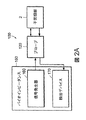
ここで、同じ参照記号が同じ部分を表している種々の図面を参照すると、図2Aには、本発明による、バイオインピーダンス測定デバイスまたはバイオインピーダンス測定プローブ120並びに信号発生・検出デバイス150を含む、バイオインピーダンス測定装置100を示すブロック図が示される。信号発生・検出デバイス150は、信号発生器160および検出デバイス170を含み、その各々は信号発生および検出機能を実行するための回路を構成する。信号発生・検出デバイス150は、バイオインピーダンス測定プローブ120に操作可能にまた電気的に接続され、このプローブは、電極122を介して子宮頚部組織2へ電気的に接続される(図3A)。この方法により、またより具体的に図3Aに示されるように、バイオインピーダンス測定プローブ120が組織3と電気的に接触すると、信号発生・検出デバイス150と子宮頚部組織の間に電気回路または経路が確立されて有効となる。当分野に知られているように、かかる経路が確立されると、信号発生・検出デバイス150により、より具体的にはこれらの信号発生器160により生成される信号(すなわち、電流/電圧)が、子宮頚部組織3を通って流れることができる。
Description of the preferred embodiments herein, the same reference characters refer to the various figures represent the same portion, FIG. 2A, in accordance with the present invention, bio-impedance measuring device or
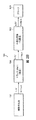
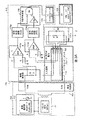
図2B、図3Aに示されるように、信号発生器160は、関数発生器162、降圧器(step down transformer)164および外部負荷源166を含むことができる。出力される電流の強さおよび周波数を制御することにより、試料を流れる出力電流が細胞膜を透過して、子宮頚部組織の抵抗の測定値を効果的に提供でき、周波数を制御することにより、電流が組織を流れるにつれて分散され、インピーダンスが測定可能となる(すなわち、電流の十分な分散を許容することなく組織をまっすぐには流れられないような周波数とする)。具体的な態様において、信号発生器160は、組織を流れる電流が0.5mAを超えないように制限されるよう、そして印加される電圧が3V未満となるように、構成および配置される。さらなる実施態様において、信号発生器160は、0.1mAおよび50kHzの正弦波電流が生成されて子宮頚部組織3を流れ、組織に印加される電圧が約1.5Vであるように、構成および配置される。
As shown in FIGS. 2B and 3A, the
図3Aにさらに詳細に示されるように、関数発生器162は、単一のXR2206波形発生器IC周辺に形成される回路である。該回路は、1Hz〜1MHzの正弦波、方形波または三角波を4つの切換レンジで生成する。高および低レベル出力の両方があり、レベルコントロールで調節可能である。このXR2206ICは、内部方形波発振器を含み、この周波数はタイミングキャパシタおよび電位差計によって制御される。方形波は微分されて(differentiate)三角波を生成し、次いで正弦波を生成するよう成形される。さらに含まれるのは、正弦波の純度を調節するために設定される2つのプリセット抵抗器である。波形スイッチは、単極3方向回転スイッチであり、ワイパー・アームが波形を選択し、全波形の振幅を制御する電位差計に接続される。
As shown in more detail in FIG. 3A, the
高出力において、方形波に対する最大振幅はピーク間約3V、三角波および正弦波に対する最大振幅もまた約3Vである。好ましい態様において、関数発生器は9VのDC電源により電力供給される。かかる関数発生器は、出力範囲内では歪(distortion)が1%未満であることが、試験によって示された。9VのバッテリーまたはDC電源を選択したのは、患者の安全を保証するためにガルバニック分離(galvanic separation)を維持する必要がないためであるが、関数発生器が当業者に知られている多数の電源の任意のものを用いて電力供給されること、またかかる電源が、それが必要な電源に適当なガルバニック分離を提供することも、本発明の範囲に含まれる。 At high power, the maximum amplitude for square waves is about 3V between peaks, and the maximum amplitude for triangular and sine waves is also about 3V. In a preferred embodiment, the function generator is powered by a 9V DC power source. Tests have shown that such a function generator has less than 1% distortion within the output range. The 9V battery or DC power supply was chosen because there is no need to maintain galvanic separation to ensure patient safety, but many function generators are known to those skilled in the art. It is within the scope of the present invention to be powered using any of the power supplies and that such power supplies provide appropriate galvanic isolation for the power supplies it needs.
信号発生器160は、母親および胎児の安全をさらに保証するため、子宮頚部組織3に印加される電圧をさらに降下させるために、降圧器164を含む。図3Aにさらに詳しく示すように、典型的な実施態様において、降圧器は、関数発生器162の出力に操作可能に結合されたMET39(3:1)エンキャプシュレートトランスである。さらに具体的な態様において、MET39(3:1)エンキャプシュレートトランスは、関数発生器162から入力された電圧が1.5Vの場合、出力電圧すなわち子宮頚部組織3に印加される電圧を、0.5Vにする。
The
降圧器を設けることに加えて、信号発生器は、限流抵抗器などの外部負荷源166を含み、それによって生成され子宮頚部組織3を通ることができる最大電流を制限し、患者および測定装置100を操作する作業者の安全を高める。子宮頚部2のバイオインピーダンスが数百オームを超えないことが予想される場合、より小さい電流の使用が適当である。実施態様において、外部負荷源166は約3.3kΩの外部負荷であり、従って信号発生器160の出力は印加電圧の0.5Vであり、それによって50kHzで最大電流0.14mAが生成される。図3Aにさらに詳細に示すように、信号発生器160の出力電流はプローブ120を通って子宮頚部組織3を透過する。得られた電圧降下は検出デバイス170で測定する。
In addition to providing a step-down device, the signal generator includes an
周波数、電流および電圧の一定条件下において、哺乳類の組織は、任意の電気回路素子(例えば抵抗器)と同様のインピーダンスまたは抵抗などの電気的特性を示すことができる。従って、バイオインピーダンス測定プローブ120は、子宮頚部2の組織3に電気的に結合されることにより、信号発生・検出デバイス150の検出デバイス170において検出される電気的パラメータ(例えば電圧)に電気的に結合される。検出デバイス170を含む回路は、組織が示す1つまたは2つ以上の電気的特性を、検出した情報に基づいて決定または計算する。さらに具体的な態様において、検出デバイスはまた、観察または測定された1つまたは2つ以上の電気的特性の出力(例えば視覚的表示)を提供することができる。例えば、検出デバイス170は、例えば組織の抵抗またはインピーダンスおよび位相角などを検出するのに用いることのできる、当業者に知られた多数のマルチメーター型のデバイスの任意のものであってよい。
Under certain conditions of frequency, current and voltage, mammalian tissue can exhibit electrical properties such as impedance or resistance similar to any electrical circuit element (eg, resistor). Accordingly, the
1つの実施態様において、検出デバイスはExtech MM560 True-RMS Multimeterであり、これは、良好な解像度を示し、1μV、0.0001Hz、0.01μAおよび0.1°までの測定を可能とする、True-RMSマルチメーターである。Extechモデルはまた、非常に携行性に優れ(400g未満)、従って信号発生・検出デバイス150に組み込むことができる。これはまたバッテリーで駆動されるため、デバイスへの電力供給に外部電源は必要としない。さらに、Extechはコンピュータとのインターフェイスを可能とするソフトウェアパッケージを搭載しており、データ保存および解析が容易である。
In one embodiment, the detection device is an Extech MM560 True-RMS Multimeter, which shows good resolution and allows measurements up to 1 μV, 0.0001 Hz, 0.01 μA and 0.1 °. -RMS multimeter. The Extech model is also very portable (less than 400 g) and can therefore be incorporated into the signal generation and
他の実施態様において、また図3Aに示すように、バイオインピーダンス測定プローブ120の電極122のうちの2個は、子宮頚部組織3内に得られた電圧を測定し、得られた電圧は、差動増幅器172bで増幅され、差動増幅器はまた信号源からのノイズを減少させて、増幅された信号は信号変換回路174aに入力される。また、降圧器164からの信号出力は差動増幅器172aで適切に処理され増幅されて、信号変換回路174bに入力される。
In other embodiments, and as shown in FIG. 3A, two of the
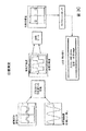
図3Bも参照すると、信号変換回路174a、bは、それぞれの信号変換回路へ入力された正弦波電圧信号を、例えば一連のhexインバータによって方形波信号へと変換するよう、構成および配置される。正弦波を子宮頚部組織3内に導入するのは、方形波の特性が奇数次高調波を有するために、組織3への信号生成のプロセスが複雑になるためである。電圧信号は方形波へ変換されるが、これは、ゼロ交差点が比較的顕著に検知されるからである。
Referring also to FIG. 3B, the
それぞれの信号変換回路174a、bから出力される2つの方形信号は、プログラム可能インタラプト・コントローラ(PIC 16F877)マイクロプロセッサ・チップ178に操作可能に結合された、一連の論理回路から構成される代数式加算器176において、代数的に処理される。PIC178は、2つの信号間の位相差を測定する。位相測定は幾つかの部分を含む。入力AC電源は、基準抵抗器(A波;純抵抗)および実際の子宮頚部組織(B波:抵抗+キャパシタンス→Z=R+jX)を流れる。基準抵抗器の値を、例えば、妊娠していない女性の子宮頚部組織の平均抵抗値となるよう選択する。B波は、子宮頚部組織3の容量効果のために負の位相シフトを有する。B波はまたノイズの問題も有するため、シュミットトリガおよびローパスフィルターを加えて、位相解析の前に信号をクリーンアップすることができる。
The two square signals output from each
その結果、論理ANDゲートを用いて2つの波(A波、B波)を代数的に差し引き、2つの方形波の間の差を決定して(C波)、これによって位相角についての情報を提供する。PICのサンプリング率を用い、PICのタイマーを用いてC波の幅を測定および計算し、これが位相角である。 As a result, a logical AND gate is used to algebraically subtract the two waves (A wave, B wave) to determine the difference between the two square waves (C wave), thereby obtaining information about the phase angle. provide. Using the PIC sampling rate, the PIC timer is used to measure and calculate the C-wave width, which is the phase angle.
強さおよび位相の測定値は、例えばPICチップ178によってプログラムされ更新されるLCD190を用いて表示する。PIC178の更新速度は連続的とみなされるだけ十分に速いため、2ラインLCDディスプレイは、リアルタイムのように、取り込んだインピーダンス測定値を連続して表示する。この方法により、ルックアップチャートを用いる産科医−婦人科医、臨床医または診断医は、インピーダンス測定値を比較して、分娩誘発リスクについての患者の読み取り値がどうであるかを決定することができる。好ましくは、更なる態様において、LCDディスプレイは、分娩誘発リスクに関する付加的情報を自動的に表示するよう、さらに制御される;すなわち、読み取った値が正常範囲を超えていることの示唆を提供するか、または測定値を表示する代わりに正常範囲外のメッセージを提供する。
バイオインピーダンス測定装置100の使用は、図4A、4Bを参照した以下の考察から最良に理解することができる。図4Aに示されていない、バイオインピーダンス測定装置100のさらなる詳細については、図2〜3も参照する。
The intensity and phase measurements are displayed using an
The use of the
使用の前に、バイオインピーダンス測定プローブ120を信号発生・検出デバイス150から切り離し、測定プローブを、当業者に知られた、測定プローブの構成に適合する多数の技法の任意のものを用いて滅菌する。1つの実施態様において、プローブは、標準のオートクレーブユニットにおいて、かかる使用のために確立されたプロトコルおよび方法に従って滅菌される。損傷の可能性を最小化するため、オートクレーブのフルサイクルモードではなく、フラッシュまたは迅速滅菌プロトコルを用いてもよい。以下に提供されるように、測定プローブを構成する材料は、典型的なオートクレーブ温度(例えば160°F)に適合するよう選択するのが好ましい。滅菌の後、測定プローブは、信号発生・検出デバイス150に再接続する前に冷却される。滅菌の他の方法は、プローブを各使用の後にエチレングリコール溶液に浸すことである。
Prior to use, the
代替的な態様において、測定プローブ120は製造業者によって滅菌され、キットまたはパッケージ内に滅菌された状態で提供される。かかる場合には、滅菌測定プローブ120を保護パッケージから取り外して、信号発生・検出デバイス150に接続する。
臨床医/診断医/医療従事者(すなわちユーザー)は、信号発生・検出デバイス150を起動することにより、プローブ電極122から所望の電流および電圧を組織へ出力できるように、また組織の所望の電気的パラメータ(例えば電圧)を検出し、1つまたは2つ以上の所望のパラメータ値を決定して出力できるようにする。臨床医/診断医は次に、測定プローブ120を哺乳類の身体に設けられている開口部内に挿入し、ここで、この実施態様においては該開口部は自然の身体の開口部(すなわち膣)である。測定プローブの挿入は、プローブの先端部材124が身体開口部内にあり、シャフト部材126の一部は外部に留まってユーザーによる取り扱い操作ができるようにする。自然の身体開口部の使用が考えられているが、測定プローブは例えば手術的介入などにより形成された開口部に挿入することも考えられる。
In an alternative embodiment, the
The clinician / diagnostic / healthcare worker (ie, user) can activate the signal generation and
臨床医/診断医または医療従事者は測定プローブ120をさらに操作して、電極122が検査/評価されるべき組織の近くに位置するようにし、全部の電極がこれらの組織と接触するようさらに操作する。より具体的な態様において、測定プローブ120は、電極122が子宮頚部組織の近くでそれに接触するように操作される。測定プローブ120を挿入して、プローブ電極122を子宮頚部組織3に接触させた後、測定プロセスが開始され、測定されたパラメータがユーザーに表示される。
The clinician / diagnostic or medical professional further manipulates the
本明細書に記載されるように、さらなる態様において、バイオインピーダンス測定プローブ120はさらに、プローブ電極122への電圧および電流の印加を手動で制御するための機構を含むように、構成および配置される。この方法により、電流を組織に供給するプローブ電極122は、デバイスが操作される間エネルギーが供給されない。これによって、患者、胎児およびユーザーの安全のためのさらなる方法が提供される。従って、プローブを挿入してプローブ電極122を子宮頚部組織3と接触させた後、臨床医/診断医が制御機構(例えばスイッチ)を起動させると、測定プロセスが上記のように開始される。
As described herein, in a further aspect, the
1つまたは2つ以上のバイオインピーダンスパラメータおよび/または他の関連する診断情報を得るかまたは測定した後、ユーザーはプローブ電極を配置し直して、子宮頚部組織に対して異なる配置となるようにする。これは、ユーザーがプローブ電極122を子宮頚部組織から離し、電極が異なる配置(例えば、測定プローブを回転させる)となるよう測定プローブ120を操作することで実施される。測定プロセスの完了後、ユーザーは測定プローブを身体の開口部から引き出す。
After obtaining or measuring one or more bioimpedance parameters and / or other relevant diagnostic information, the user repositions the probe electrode to a different placement relative to cervical tissue. . This is accomplished by the user operating the
得られたバイオインピーダンス情報から、臨床医/診断医は、子宮頚部組織の潤軟度、引張り強さ(tensile strength)および新生物の浸潤の可能性についての推測を引き出すことができる。かかる情報は、新規な方法によって重要な臨床管理の意思決定を支援および強化するが、これは、従来の技法を用いてこの情報が臨床的に顕著または検知可能になるよりも早い時点で、「組織レベル」の解析が非侵襲的な様式で利用可能となるからである。 From the obtained bioimpedance information, the clinician / diagnostician can draw inferences about the cervical tissue softness, tensile strength and possible neoplastic infiltration. Such information supports and enhances important clinical management decisions through novel methods, at an earlier point in time than this information becomes clinically significant or detectable using conventional techniques. This is because “tissue level” analysis is available in a non-invasive manner.
本明細書に示されるように、早期分娩をもたらす可能性のある多くの状態が存在し、原因に関わらず、妊娠中の子宮頚部の軟化、拡張および展退並びに陣痛は、子宮収縮のみの結果として起こるのではなく、子宮頚部の構造の能動的なリモデリングの結果でもある。陣痛への移行の際、ヒト妊娠子宮頚部の組織は大きなリモデリングを受けて、その主要なコラーゲン基質がグリコサミノグリカンによって置き換えられる。このコラーゲン基質の減少は、図5に提供されるグラフからも見ることができる。 As shown herein, there are many conditions that can lead to preterm labor, and regardless of the cause, cervical softening, dilatation and extension during pregnancy and labor are the result of uterine contractions only. It does not occur as a result of active remodeling of the cervical structure. Upon transition to labor, the human cervical tissue undergoes major remodeling, and its major collagen matrix is replaced by glycosaminoglycans. This decrease in collagen matrix can also be seen from the graph provided in FIG.
この「成熟」の結果子宮頚部が軟化し、これによって、胎児が子宮から出ることを可能にするために最終的に必要とされる薄化および拡張に備える。コラーゲンのグリコサミノグリカンに対する比率が減少するに従って、子宮頚部の物質はより疎水性となる。これが、組織の電気伝導性における変化として測定可能な性質または特性である。かかるバイオインピーダンスの変化は、指による触診によって臨床的に検知されるよりもはるか前に、組織レベルで検知可能である。 This “maturation” results in softening of the cervix, thereby preparing for the thinning and expansion ultimately required to allow the fetus to leave the uterus. As the ratio of collagen to glycosaminoglycan decreases, the cervical material becomes more hydrophobic. This is a property or characteristic that can be measured as a change in tissue electrical conductivity. Such bioimpedance changes can be detected at the tissue level long before it is clinically detected by finger palpation.
本発明の方法は、従来技法に比べて陣痛の開始をより早く検知することができるため、許容できる在胎期間と胎児の発達レベルに到達するまで陣痛を遅延させるのに非常に効果的な、幾つかの処置を考慮して実施することができる。そのため、検知が妊娠期間の初期において実施され把握されるので、これらの処置は妊婦に対しより有効で安全であることが期待される。また、羊膜破裂の前に検知できる可能性が高いために、一旦羊膜が破裂すると子宮および胎児の感染の医療リスクが増加するためその使用が安全ではない薬剤を、処置に用いることができる。 The method of the present invention can detect the onset of labor more quickly than conventional techniques, and is therefore very effective in delaying labor until reaching an acceptable gestational age and fetal developmental level, Several treatments can be considered. Therefore, since detection is performed and grasped in the early stage of pregnancy, these treatments are expected to be more effective and safe for pregnant women. Also, drugs that are unsafe to use can be used for treatment because the possibility of detection before rupture of the amniotic membrane increases the medical risk of infection of the uterus and fetus once the amniotic membrane ruptures.
従って、さらなる態様において、臨床医/診断医はバイオインピーダンス測定結果に基づき、床上安静などの簡単なものから陣痛を延期するため、またはその進行を阻むために投与可能な薬剤までの多様な、適切な処置を決定できる。かかる薬剤は、限定はされないが、βアドレナリン作動性受容体作動薬、硫酸マグネシウム、カルシウムチャネル遮断薬、シクロオキシゲナーゼ阻害薬、サルブマトール、リドカインおよび酸化窒素/酸化窒素供与体を含む。コルチコステロイドもまた、未成熟な胎児に対する具体的な処置として、器官の成熟を増強するため、また肺の発達を早めることによって胎児の肺機能を改善するため、また酸素交換に必要な呼吸酵素として、頻繁に用いられる。これらはまた脳室内出血および消化管の障害のリスクを減少させることができる。 Thus, in a further aspect, the clinician / diagnostic is based on bioimpedance measurement results and varies from a simple one such as bed rest to an agent that can be administered to postpone labor or to prevent its progression. The treatment can be determined. Such agents include, but are not limited to, beta-adrenergic receptor agonists, magnesium sulfate, calcium channel blockers, cyclooxygenase inhibitors, salbumatol, lidocaine and nitric oxide / nitric oxide donors. Corticosteroids are also a specific treatment for immature fetuses, to enhance organ maturation, to improve fetal lung function by accelerating lung development, and to the respiratory enzymes required for oxygen exchange As frequently used. They can also reduce the risk of intraventricular hemorrhage and gastrointestinal disorders.
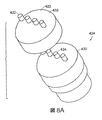
図6A−6Dをここで参照すると、本発明によるバイオインピーダンス測定プローブ220の1つの態様が示される。測定プローブ220は、上端部材224、シャフト部材226、複数の、より特に4個または5個以上の、さらに具体的には4個の電極222、および相互接続ワイヤ228を含む。シャフト部材226は、その中を相互接続ワイヤ228が通る、軸方向に伸びるルーメンまたは直通開口部(through aperture)225を含む。シャフト部材226はまた、その端部227が上端部材の一部を直通開口部内に受けいれるように配置される。この方法で、上端部材224はシャフト部材226と機械的に接続されて、上端部材およびシャフト部材が一体構造を形成する。さらなる態様において、上端部材224はシャフト部材226と取り外し可能に接続され、力を加えることにより上端部材がシャフト部材から取り外されて、交換または他の作用に用いることができる。
Referring now to FIGS. 6A-6D, one embodiment of a
上端部材224は、電極が上端部材中に配置されて上面223から伸びており、そして軸方向に伸びるように、構成および配置される。各電極はまた、各電極の端部が上端部材の上面223から規定の距離はなれて位置するのに十分な長さを有するよう、構成および配置される。電極222の各々はまた、四面体、直線で囲まれた形または円形のアレイを含む非直線電極アレイを形成または規定するよう配置される。より具体的な実施態様において、電極222は上端部材224内に、正方形の四極性電極アレイを形成する正方形アレイを形成するよう、配置される。
The
相互接続ワイヤ228は、各電極を正方形の四極性電極アレイと共に用いるために特に構成および配置された、信号発生・検出デバイス150に相互接続される。四極性電極アレイは、抵抗測定のVan der Pauw法と共に用いられる場合、バイオインピーダンス測定の平均された読み取り値を得ることを可能にする。この技法によれば、そして図14も参照すると、抵抗値の読み取りは試料領域の4点で行われ、次にこれらの読み取り値の修正幾何平均を取ることにより、組織全体の抵抗値を計算する。この技法を本発明で用いるのは、試料である組織の面積が非常に小さい(〜2mm2)ためである。さらに、子宮頚部組織内でバイオインピーダンス値が変動するため、平均値はより高い一貫性を提供する。
Van der Pauw法は、任意の四角い試料または円形領域上に規定された4つの試料点に渡る一連の電位差を作ることを含む。この方法によれば、1組のプローブ電極222(すなわち、4個の電極のうちの任意の2個)は、信号発生器160に相互接続され、子宮頚部組織を通って流れる電流が供給される。プローブ電極の他の組(すなわち、4個の電極のうちの他の2個)は、検出デバイス167に結合されて、電位差を測定する。このセットアップを次に、プローブ電極222の可能な組み合わせ全てで展開させる。従って、プローブ電極222の2個は電位差測定のために検出デバイス170の先端に接続され、プローブ電極222の2個は、信号発生器160からの出力に接続される(電圧および電流が、それぞれトランスおよび外部負荷によって降下された後に)。この方法のための適切な式を用いることにより、平均読み取り値が得られる。
The Van der Pauw method involves creating a series of potential differences across four sample points defined on any square sample or circular area. According to this method, a set of probe electrodes 222 (ie, any two of the four electrodes) are interconnected to signal
例示の実施態様において、電極222は上端部材224に固定される。代替的な態様において、電極222および上端部材224は当業者に知られた多数の技法の任意のものを用いて構成および配置され(例えば、バネ荷重電極、スライド電極)、それによって、電極が上端部材上面223に対して本質的に横向きに固定されるように、そして電極は、軸方向または長さ方向に動くことができ、上端部材上面223に対して内向きまたは外向きに動けるように維持される。
In the illustrated embodiment, the
上端部材224およびシャフト部材226は、意図された使用に適当な断面形状およびサイズを有するのが好ましい。実施態様において、先端およびシャフト部材224、226が互いに固定されている場合、それらは一般に円筒状部材を形成して、ルーチンの産科学的または婦人科学的検査の際に膣に挿入することができ、また、ユーザーによって操作可能なデバイスを提供することができる。シャフト部材226の長さは、図3Aに示すように、ユーザーがバイオインピーダンス測定プローブ220を身体開口部(例えば膣)の外側で操作できるように設定される。
先端およびシャフト部材224、226の各々は、意図された使用に適当であり、生体適合性のある材料で構成される。材料はまた、医療処置/身体開口部への挿入におけるその使用の前にバイオインピーダンス測定プローブ220を滅菌するのに用いられる、滅菌プロトコル(例えば加熱)に好適であるのが好ましい。シャフト部材226のための材料はまた、シャフト部材が操作される間および電極222が子宮頚部組織との接触を維持されている間にそれにかかる、予想される負荷および力に対して適切である。
Each of the tip and
電極は、意図された使用に適切なサイズであり、生体適合性があって意図された使用に適切な材料から構成される。かかる材料には、金、銀および銅並びにこれらの合金が含まれ、具体的な態様においては、電極は銀−銅合金から作製される。前記は例示であり、ステンレススチールなどの他の材料も、かかる他の材料の電気的および材料特性が意図された使用に満足できるものであれば用いることができる。 The electrodes are of a size that is appropriate for the intended use and are composed of a material that is biocompatible and suitable for the intended use. Such materials include gold, silver and copper and alloys thereof, and in a specific embodiment, the electrode is made from a silver-copper alloy. The foregoing is exemplary, and other materials such as stainless steel can be used if the electrical and material properties of such other materials are satisfactory for the intended use.
図7A〜7Fを参照すると、上端部材324の態様の種々の図が示されており、該部材は、電極322が、それぞれの上端部材の上面323の幅にわたりまたは放射状に伸びる、1つまたは2つ以上の直線電極アレイを形成するように配置されるよう、構成および配置されている。1つまたは2つ以上の直線電極アレイの各々は、複数の電極322から、より特定的には4個または5個以上の電極から構成され、例示の実施態様においては4個の電極から構成されている。電極322はまた、場の分散問題と電極の不均一性を最小化するように、互いに間隔をあけて配置される。かかる直線電極はまた、無視可能な電極極性を有する設計を生み出す。図7A〜7Fに示されている上端部材は、例えば図6に示されたシャフト部材226などのシャフト部材と共に用いられることが考慮される。そのため、シャフト部材の詳細については図6についての前記考察を参照のこと。
Referring to FIGS. 7A-7F, various views of an embodiment of an
各直線電極アレイは直線四極性プローブアレイを含み、該直線四極性プローブアレイにおいては、2個の電極が信号発生器160に電気的に結合され、他の2個の電極は検出デバイス170に電気的に結合されている。例示の実施態様において、各直線アレイの外側の2個の電極は信号発生器160に電気的に結合され、本発明の他の態様によれば、内側の2個の電極は検出デバイス170に電気的に結合される。
Each linear electrode array includes a linear quaternary probe array in which two electrodes are electrically coupled to the
図7A〜7Cに示される態様において、電極322は上端部材の上面323から距離を有して、露出された電極端部、すなわち子宮頚部組織に接触する端部が、全ての電極について上面から同じ間隔をあけるように配置される(すなわち、全ての電極端部が同じ平面上にある)。ここで図7Dを参照すると、本発明の他の態様による先端部材324aが示されている。この態様においては、電極の露出部の長さを制御して、露出された電極の端部が対向する接触すべき解剖学的な面を本質的に反映するようになっている。1つの実施態様において、2個の内側の電極の露出部の長さは、外側の2個の電極の露出部よりも、上面323からさらに伸びている。
In the embodiment shown in FIGS. 7A-7C, the
ここで図7E、7Fを参照すると、上端部材324b、cのさらなる実施態様の上面図が示されており、これらは複数の直線電極アレイで構成されている。図7Eに示された上端部材324bの態様は、互いに角度を有するよう配置された2つの直線アレイで構成される。さらに特定の態様において、アレイは、各アレイの中点が共通するように配置される。より具体的な態様において、2個の直線電極アレイは、互いに直交するように配置される。図7Fに示された上端部材324cの態様は、複数の直線電極アレイを含むよう構成され、より具体的には8つの直線電極アレイであって、各アレイが隣接する直線アレイと角度を有するように配置された該アレイを含むように構成される。隣接するアレイの間の角度が同じかまたは異なることは、本発明の範囲である。
Referring now to FIGS. 7E and 7F, there is shown a top view of a further embodiment of the
上記のように、図7A〜7Dに示される上端部材の態様については、2個の電極は信号発生デバイス160に結合され、他の2個の電極は検出デバイス170に結合される。図7E、7Fに示される態様においては、各直線アレイの電極が選択的に信号発生デバイス160および検出デバイス170に結合され、各アレイは順番に、該直線アレイが結合された領域の子宮頚部組織のバイオインピーダンスを測定するようになっている。この方法により、ユーザーは、前の配置から異なる位置の電極が有効な場所における複数のバイオインピーダンス測定値を得ることができ、従って複数得られたバイオインピーダンス値を平均して、平均値を得ることができる。
As described above, for the top member embodiment shown in FIGS. 7A-7D, two electrodes are coupled to the
かかる配置はまた、ユーザーがシャフト部材226(図6A)を操作することにより各データを得るために電極を再度配置させる必要性を排除する。これによってデータ取得をスピードアップし、他のデータ取得のために電極を再配置させるよう測定プローブを操作する時に生ずるストレスおよび不快感を減ずることができる。
ここで図8A、8Bを参照すると、本発明の他の側面による上端部材424が示されており、これはベース部430および取り外し可能なカバー部432を含むよう構成および配置されている。図8A、8Bに図示された上端部材は、図6に示されたシャフト部材226などのシャフト部材を組み合わせて用いることが意図される。従って、シャフト部材の詳細については図6についての前記考察を参照のこと。また、図8A、8Bに図示された態様は直線電極アレイまたは直線四極性アレイ上のものであるが、図6、7の任意の図に示された任意の上端部材の態様が、ベース部および取り外し可能なカバー部を含むように構成可能であることが意図される。
Such an arrangement also eliminates the need for the user to reposition the electrodes to obtain each data by manipulating the shaft member 226 (FIG. 6A). This speeds up data acquisition and reduces the stress and discomfort caused when operating the measurement probe to reposition the electrodes for other data acquisition.
Referring now to FIGS. 8A and 8B, there is shown an
ベース部430は、図6、7に記載された上端部材224、324の任意のものと同様の様式で、前記考察を参照して、シャフト部材226に固定される。ベース部430はまた、ベース部の上面から外向きに伸びている複数の電極434を含むように構成および配置される。ベース部電極434はまた、カバー部内に設けられた電極422の配置を反映するよう配置される。例示の態様において、ベース部電極434は、カバー部内に形成された直線アレイの電極の間隔および配置を反映する直線電極アレイを形成するよう配置される。
使用においては、カバー部は、カバー部の底に向かって下向きに伸びる開領域433を含むよう、構成および配置される。開領域433およびベース部の対応面は、カバー部が取り外し可能に、機械的に互いにはめこまれてカバー部がベース部に保持されるような、好ましいサイズで構成される。さらに、カバー部電極422は、その底部端にポケットまたは軸方向に伸びる開口を形成するよう、構成および配置され、ここで底部電極434の1つの対応する部分を受け取り、それによってこれらの電極422、434の間の雄雌型の電気的接続を形成するようになっている。カバー部電極422およびベース部電極434は当業者に知られた任意の接続技術を用いて適合可能であり、それによって、カバー部432がベース部430に取り外し可能に固定された場合に、対応する電極間に電気的接続を形成することが意図される。
In use, the cover portion is constructed and arranged to include an open region 433 that extends downwardly toward the bottom of the cover portion. The open area 433 and the corresponding surface of the base part are configured in a preferred size such that the cover part can be removed and mechanically fitted together so that the cover part is held on the base part. Furthermore, the
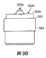
ここで図9〜10を参照すると、二極性バイオインピーダンスプローブ用の上端部材524が示される。図9A〜9Dに図示された上端部材は、図6に示されたシャフト部材226などのシャフト部材を組み合わせて用いることが意図される。従って、シャフト部材の詳細については図6についての前記考察を参照のこと。かかる上端部材は、中心電極522a、中心電極の周囲を囲むよう配置された内側環状電極522b、および内側環状電極の周囲を囲むよう配置された外側環状電極522cを含む。
Referring now to FIGS. 9-10, an
図9B〜9Dにさらに明確に表されているように、中心電極および環状電極522a〜c各々の端部は、それぞれ、対向する子宮頚部組織の接触面を反映するよう構成および配置される。さらに、中心電極522aは、中心電極によって子宮頚部組織に導入される電流が、該子宮頚部組織内の所望の深さに到達するよう、構成および配置される。また、内側環状電極522bは、中心電極によって子宮頚部組織に導入される電流が、一般に組織表面に残るよう、構成および配置される。これは、中心電極522aから導入される電流をさらにバイアスさせて、子宮頚部組織のより深い所へと到達させる。
As more clearly represented in FIGS. 9B-9D, the ends of each of the central and
使用において、また図10に示されるように、中心電極および内側環状電極は信号発生デバイス160に結合されて、これらの2つの電極により子宮頚部組織に同じ電圧が印加され、外側環状電極522cが電気回路を形成または完成させる。図10にも示されるように、検出デバイスは2個の電極間にあって組織の電圧を測定するよう、配置される。
上端部材524および電極の材料については、図6〜7に関する前記の考察を参照のこと。ただし、電極は他の導電性材料からも作製できることが意図される。
In use, and as shown in FIG. 10, the center electrode and the inner annular electrode are coupled to the
See the discussion above regarding FIGS. 6-7 for materials of the
ここで図12を参照すると、本発明の他の側面による、バイオインピーダンス測定装置600の立体分解図が示される。かかる装置は、バイオインピーダンス測定プローブ610、バネ620およびハンドル部材650を含む。バイオインピーダンス測定プローブ610は、本明細書に記載された任意の測定プローブを含み、ここでシャフト部材612は、バネ620の1端がそこで静止するストッパー614をさらに含むように構成される。
ハンドル部材650は、信号発生器160と検出デバイス170およびLCDディスプレイ190を含む、信号発生・検出デバイス150を収納するよう構成および配置される。ハンドル部材650はまた、ベースまたは端部を有して軸方向に伸びる開口部と共に構成され、ここで開口部は、バネ620およびシャフト部材612の一部を受領する。バネ620の他の端は、測定装置600が組み立てられた場合にはハンドル開口部652のベースまたは端部上に静止する。
Referring now to FIG. 12, a three-dimensional exploded view of a
The
使用においては、ユーザーは、ハンドル部材650を操作して上端部材616を身体の開口部に挿入し、その後ハンドルを操作して、電極618を子宮頚部組織3の近辺に位置させて接触させる(図4A)。バネ620は、ハンドルの動きで導入される任意の力の変化に関わらず、電極が組織に適用する力に感知可能な変化が現れることなく、電極が一般に子宮頚部組織に連続して接触するように維持されるよう、構成および配置されるのが好ましい。これにより、電極から組織へ付与される力が大きく変化することがないため、ハンドルへかかる力がたとえ変化しても、測定されるバイオインピーダンスは大きく変化することはない。またバネは、ハンドルの軸方向の動きでかかり得る最大の力を制限して、所望の値より低くするように構成されるのが好ましい。
In use, the user manipulates the
図12にも示すように、また本明細書に記載されているように、ハンドル部材650はスイッチまたはボタン660を含むよう配置され、該スイッチまたはボタンは、信号発生器160の起動、および/または、電流を子宮頚部組織内へ注入する1個または2個以上の電極と信号発生器との間の電気的相互接続機構の起動の制御に用いられるものである。かかる態様において、回路およびボタン660は、ボタン660が起動された時以外には電流が流れず、また電圧が電極にかからないように配置される。
As also shown in FIG. 12, and as described herein,
ここで図13を参照すると、本発明によるバイオインピーダンス測定システム800であって、本明細書に開示され教示された任意のバイオインピーダンス測定装置100、600、および本明細書に開示され教示された任意のバイオインピーダンス測定デバイスと組み合わせて用いるための、前記測定システムが示される。説明目的のために、以下の考察では図2Aのバイオインピーダンス測定装置100および図2A、3Aのバイオインピーダンス測定デバイス120を引用する。従って、以下に記載されていないこれら装置およびデバイスの特徴および要素のさらなる詳細については、これらの図に対する考察を参照する。
Referring now to FIG. 13, a
バイオインピーダンス測定システム800はまた、通信インターフェイス810およびコンピュータ処理システム820を含む。コンピュータ処理システム820は、当業者に知られている多数のシステムの任意のものであり、一般に以下を含む:例えばデータ処理、計算の実行およびI/O制御操作などのためにアプリケーションプログラムおよびオペレーティング・システムを実行するマイクロプロセッサおよびランダム・アクセス・メモリ、さらに固定記憶装置またはメモリシステム(すなわち、コンピュータシステムへの電力がオフにされた後も情報を保持するシステム)であって、例えば磁気ハードディスクおよび/または光学ディスクを取り入れたものであり、ここでストレージシステムはまた、かかる磁気ハードディスクおよび光学ディスクの外部アレイを含むこともできる(例えばRAID構造)。
通信インターフェイス810は、当業者に知られている多数の通信システム、デバイス、または装置の任意のものであって、それによって情報が選択的に、例えば本発明の信号発生・検出デバイス150aなどの外部入力デバイスから、コンピュータ処理システム820へと伝達されるものである。かかる通信インターフェイス810は、当業者に知られている多数の通信技術の任意のものを取り入れることができ、無線通信技術(例えばRFおよびIR)、有線通信技術(例えば電気信号および光学信号)、およびインターフェイスデバイス(例えばドッキングステーション)、さらにかかる通信技術の組み合わせを取り入れたシステムなどを含む。さらに、本発明による通信インターフェイス810はまた、ワイドアレイおよびローカルエリア・ネットワーク、さらにインターネットを介して通信する具体化された通信システムを含むことが理解される。
The
1つのコンピュータ処理システム820との通信が示されているが、これが本発明に対する限定とは考えられないことが理解されるべきであり、なぜならば、かかる通信は、バイオインピーダンス測定装置と2つ以上のコンピュータシステムとの間で行うことも意図されるからである。例えば、得られたバイオインピーダンス測定データは、特定ユーザーのコンピュータシステムおよび、組織学的検査目的でデータを取得することを課されている他のコンピュータシステムに送信することができる。代替的に、コンピュータ処理システム820は、通信インターフェイス810または他の通信システムを介して他のコンピュータシステムに接続されて、他のコンピュータシステムへ組織学的データを送信する。
Although communication with a single
本発明の信号発生・検出デバイス150aはさらに通信インターフェイスデバイス155を含み、該通信インターフェイスデバイスは、検出デバイス170により取得されたデータを、通信インターフェイス810に取り入れられた1つまたは2つ以上の通信システムへ、およびコンピュータ処理システム820へと送信するための機構を提供するよう、構成および配置されている。さらなる態様において、通信インターフェイスデバイス155はまた、コンピュータ処理システム820からの出力を受信し、これをディスプレイへと入力するよう構成および配置され、これによって処理システム出力に含まれるこの情報をディスプレイ190に表示することができる。この方法により、測定された情報に基づく診断および臨床情報を、臨床医または診断医がかかる情報のためにコンピューター処理システムへ特にアクセスする必要なく、彼らに提供することができる。
The signal generation /
1つの例示の態様において、通信インターフェイスデバイス155は多数の無線通信デバイスの任意のものか、または多数の有線通信技術の任意のもの(例えば、イーサーネット)と共に用いるデバイスである。かかる信号発生・検出デバイス150aおよび通信インターフェイスデバイス155はまた、測定されたバイオインピーダンスデータのかかるデータ通信が本質的にリアルタイムでコンピュータ処理システム820へと処理および出力されるよう、構成および配置されることが意図される。すなわち、データは取得されつつ、処理されコンピューター処理システム820へ送信される。
In one exemplary aspect, the
他の態様において、バイオインピーダンス測定データは取得されつつ、信号発生・検出デバイス150aに取得され保存される。全データの取得の後、ユーザーは通信インターフェイスデバイス155を通信インターフェイス810へと操作可能に接続し(例えば、ネットワークケーブルまたはUSBケーブルを通信インターフェイスデバイス155およびネットワーク通信システム/コンピュータ処理システムに接続する)、これによって取得したデータを、処理(例えば、バッチモード処理)のためにコンピュータ処理ステムに送信する。
In another embodiment, the bioimpedance measurement data is acquired and stored in the signal generation /
通信インターフェイスデバイス155はまた、通信インターフェイス810がドッキングステーションを含むまたは包含する場合は、ドッキングステーションとドッキングするための適切な電気的接続を含むデバイスを含むことができる。典型的には、ドッキングステーションとコンピュータ処理システム820との間に通信リンクが既に確立されている。従って、全データの取得の後、ユーザーは通信インターフェイスデバイス155をドッキングステーションに操作可能に結合することにより、取得したデータがその処理(例えばバッチモード処理)のために、ドッキングステーションを介してコンピュータ処理システムへと送信される。
The
特定の態様において、コンピュータ処理システム810はさらに、本発明によるバイオインピーダンス測定装置と組み合わせて用いられるための、固定記憶装置に格納された1つまたは2つ以上のアプリケーションプログラム822およびデータベース824を含む。1つの例示の態様において、アプリケーションプログラムは、データを取得し規定の様式でデータベースに格納し、後で臨床医/診断医が解析および評価のために検索できるための、指示書および基準を含む。例えば、診断医/臨床医はある患者についての一定期間の全測定データ(例えば、患者による異なる通院時)にアクセスでき、測定データがある傾向または変化が生じていることを示唆しているかどうかを決定し、それによって臨床医は、さらなる措置をとるべきかどうかを決定できる。産科学の領域においては、これは、早期陣痛の開始の示唆があるかどうかを決定し、それによって産科医または婦人科医が、かかる分娩を遅延させるための措置(例えば、床上安静の診断)をとるべきかどうかの決定を許容することであり得る。産科学以外の領域においては、診断医/臨床医は、この情報を、かかる変化の原因を決定するためのさらなる検査を行うべきかどうかを決定するために用いることができる。情報はまた、さらに侵襲的な試験または診断技術(例えば生検)に進む前に、他の種類の検査(例えば、子宮ガン検査)の結果のさらなる確認に用いることができる。
In certain aspects, the
さらなる態様において、データベースはまた、バイオインピーダンス測定値をより具体的な臨床または診断情報に関連づける組織学的情報を含み、簡単なものではこれは例えば、あるバイオインピーダンス測定値が当該患者についての正常値(例えば、年齢、妊娠しているかどうか、妊娠期間)からはずれていることなどである。したがってアプリケーションプログラムは、組織学的データまたは情報を取得測定データおよび患者の他の入力データと比較し、測定データに関連する組織学的臨床/診断情報を決定するための情報および基準をさらに含む。アプリケーションプログラムはまた、かかる臨床/診断情報をユーザーに出力するため、例えば情報をディスプレイ190に表示するための、指示書および基準をさらに含む。
本発明の好ましい態様を具体的な用語を用いて記述したが、かかる記述は説明目的のみであり、本クレームの精神および範囲から逸脱することなく、変更および改変を作り出せることが理解される。
In a further embodiment, the database also includes histological information that associates the bioimpedance measurement with more specific clinical or diagnostic information, which in the simplest case, for example, if a bioimpedance measurement is a normal value for the patient. (Eg, age, whether or not pregnant, pregnancy period). Accordingly, the application program further includes information and criteria for comparing histological data or information with acquired measurement data and other patient input data to determine histological clinical / diagnostic information associated with the measurement data. The application program also includes instructions and criteria for outputting such clinical / diagnostic information to the user, eg, for displaying the information on the
While preferred embodiments of the invention have been described using specific terms, it is to be understood that such description is for illustrative purposes only and that changes and modifications can be made without departing from the spirit and scope of the claims.
参照としての組み込み
本明細書に開示された全ての特許、公開された特許明細書および他の参照文献は、ここに参照としてその全体が参照により明示的に組み込まれる。
INCORPORATION BY REFERENCE All patents, published patent specifications and other references disclosed herein are hereby expressly incorporated by reference in their entirety.
等価物
当業者は、通常の実験以上のものを用いることなく、本明細書に記載された発明の具体的な態様の多くの等価物を認識または確定することができる。かかる等価物は、本クレームに包含されることが意図される。
Equivalents Those skilled in the art will recognize, or be able to ascertain using no more than routine experimentation, many equivalents to the specific embodiments of the invention described herein. Such equivalents are intended to be encompassed by the present claims.
Claims (64)
測定プローブを身体の開口部内に導入すること、ここで該測定プローブは、電極の端部が該プローブの上面から間隔をあけるように配置された複数の前記電極を含み;
子宮頚部組織に対して該測定プローブの上面の位置を変えて、前記電極の各々が前記子宮頚部組織に電気的に接触するようにすること;
前記組織と接触している前記複数電極の特定の電極にわたって電圧と電流を印加して、前記組織を電流が流れ、前記組織のインピーダンスに応答して該電流が分散されるようにすること;
前記電圧と電流を印加している間の、前記組織のインピーダンスに関連する電圧降下を、前記複数電極の特定の電極を用いて測定すること;および
前記電圧測定値に基づいてインピーダンスおよび電圧位相角を計算すること;
のステップを含む、前記方法。 A method for measuring bioimpedance of cervical tissue,
Introducing a measurement probe into a body opening, wherein the measurement probe comprises a plurality of said electrodes arranged such that the ends of the electrodes are spaced from the upper surface of the probe;
Changing the position of the top surface of the measurement probe relative to cervical tissue so that each of the electrodes is in electrical contact with the cervical tissue;
Applying a voltage and current across specific electrodes of the plurality of electrodes in contact with the tissue such that current flows through the tissue and is distributed in response to the impedance of the tissue;
Measuring a voltage drop related to the impedance of the tissue during application of the voltage and current using a particular electrode of the plurality of electrodes; and impedance and voltage phase angle based on the voltage measurement Calculating
The method comprising the steps of:
印加することが、前記4電極アレイの電極対の各々にわたって電圧と電流を連続的に印加することを含み;そして、
測定することが、前記4電極アレイの他の電極対を用いて電圧降下を測定することを含み、該他の電極対は、前記印加するのに用いる電極とは異なっている、
請求項4に記載のバイオインピーダンス測定方法。 The introduced probe comprises four electrodes arranged to form a tetrahedral array;
Applying comprises continuously applying voltage and current across each of the electrode pairs of the four-electrode array; and
Measuring includes measuring a voltage drop using another electrode pair of the four-electrode array, wherein the other electrode pair is different from the electrode used to apply,
The bioimpedance measurement method according to claim 4.
印加することが、前記直線アレイの2個の電極にわたって電圧と電流を印加することを含み;そして、
測定することが、前記直線アレイの残りの2個または3個以上の電極によって形成される電極対を用いて電圧降下を測定することを含む、
請求項4に記載のバイオインピーダンス測定方法。 The introduced probe comprises four or more electrodes arranged to form a linear electrode array;
Applying includes applying a voltage and a current across the two electrodes of the linear array; and
Measuring includes measuring a voltage drop using an electrode pair formed by the remaining two or more electrodes of the linear array;
The bioimpedance measurement method according to claim 4.
印加することが、前記4電極直線アレイを形成する4個の電極の2個にわたって電圧と電流を連続的に印加することを含み;そして、
測定することが、前記4電極直線アレイを形成する4個の電極の他の2個を用いて電圧降下を測定することを含む、
請求項4に記載のバイオインピーダンス測定方法。 The introduced probe comprises four electrodes arranged to form a linear electrode array;
Applying includes sequentially applying voltage and current across two of the four electrodes forming the four-electrode linear array; and
Measuring includes measuring a voltage drop using the other two of the four electrodes forming the four-electrode linear array;
The bioimpedance measurement method according to claim 4.
測定プローブを身体の開口部内に導入すること、ここで該測定プローブは、電極の端部が該プローブの上面から間隔をあけるように配置された複数の前記電極を含み;
子宮頚部組織に対して該測定プローブの上面の位置を変えて、前記電極の各々が前記子宮頚部組織に電気的に接触するようにすること;
前記組織と接触している前記電極の特定の電極にわたって電圧と電流を印加して、前記組織を電流が流れ、前記組織のインピーダンスに応答して該電流が分散されるようにすること;
前記電圧と電流を印加している間の、前記組織のインピーダンスに関連する電圧降下を測定すること;
前記電圧測定値に基づいてインピーダンスおよび電圧位相角を計算すること;および
前記計算されたパラメータが、陣痛開始に関連する子宮頚部組織の状態を示しているかどうかを決定すること;
のステップを含む、前記方法。 A method for detecting the start of labor,
Introducing a measurement probe into a body opening, wherein the measurement probe comprises a plurality of said electrodes arranged such that the ends of the electrodes are spaced from the upper surface of the probe;
Changing the position of the top surface of the measurement probe relative to cervical tissue so that each of the electrodes is in electrical contact with the cervical tissue;
Applying a voltage and current across a particular electrode of the electrode that is in contact with the tissue such that current flows through the tissue and is distributed in response to the impedance of the tissue;
Measuring a voltage drop related to the impedance of the tissue while applying the voltage and current;
Calculating impedance and voltage phase angle based on the voltage measurements; and determining whether the calculated parameters are indicative of cervical tissue condition associated with labor initiation;
The method comprising the steps of:
印加することが、前記4電極アレイの電極対の各々にわたって電圧と電流を連続的に印加することを含み;そして、
測定することが、前記4電極アレイの他の電極対を用いて電圧降下を測定することを含み、該他の電極対は、前記印加するのに用いる電極とは異なっている、
請求項14に記載の陣痛検知方法。 The introduced probe comprises four electrodes arranged to form a tetrahedral array;
Applying comprises continuously applying voltage and current across each of the electrode pairs of the four-electrode array; and
Measuring includes measuring a voltage drop using another electrode pair of the four-electrode array, wherein the other electrode pair is different from the electrode used to apply,
The labor detection method according to claim 14.
印加することが、前記直線アレイの2個の電極にわたって電圧と電流を印加することを含み;そして、
測定することが、前記直線アレイの残りの2個または3個以上の電極によって形成される電極対を用いて電圧降下を測定することを含む、
請求項14に記載の陣痛検知方法。 The introduced probe comprises four or more electrodes arranged to form a linear electrode array;
Applying includes applying a voltage and a current across the two electrodes of the linear array; and
Measuring includes measuring a voltage drop using an electrode pair formed by the remaining two or more electrodes of the linear array;
The labor detection method according to claim 14.
印加することが、前記複数の直線アレイの各々を形成する4個の電極のうちの2個にわたって電圧と電流を連続的に印加することを含み;そして、
測定することが、前記複数の直線アレイの各々を形成する4個の電極の他の2個を用いて電圧降下を測定することを含む、
請求項17に記載の陣痛検知測定方法。 The introduced probe comprises a plurality of linear arrays, each array comprising 4 electrodes;
Applying includes sequentially applying voltage and current across two of the four electrodes forming each of the plurality of linear arrays; and
Measuring includes measuring a voltage drop using the other two of the four electrodes forming each of the plurality of linear arrays;
The labor detection measuring method according to claim 17.
ここで決定することが、前記時系列で計算されたパラメータが陣痛開始に関連する子宮頚部組織の状態を示しているかどうかを決定することを含む、
請求項11〜19のいずれかに記載の陣痛検知方法。 The step of introducing, placing, applying, measuring, and calculating further includes performing a time series to generate a plurality of calculated time series impedance and voltage phase angles. And determining here comprises determining whether the parameters calculated in the time series are indicative of cervical tissue conditions associated with labor initiation,
The labor detection method according to any one of claims 11 to 19.
測定プローブを身体の開口部内に導入すること、ここで該測定プローブは、電極の端部が該プローブの上面から間隔をあけるように配置された複数の前記電極を含み;
子宮頚部組織に対して該測定プローブの上面の位置を変えて、前記電極の各々が前記子宮頚部組織に電気的に接触するようにすること;
前記組織と接触している前記電極の特定の電極にわたって電圧と電流を印加して、前記組織を電流が流れ、前記組織のインピーダンスに応答して該電流が分散されるようにすること;
前記電圧と電流を印加している間の、前記組織のインピーダンスに関連する電圧降下を測定すること;
前記電圧測定値に基づいてインピーダンスおよび電圧位相角を計算すること;
前記計算されたパラメータが、陣痛の開始に関連する子宮頚部組織の状態を示しているかどうかを決定すること;および、
前記決定および妊娠期間に基づき、陣痛遅延技法を実施すること;
のステップを含む、前記方法。 A method of delaying the onset of labor,
Introducing a measurement probe into a body opening, wherein the measurement probe comprises a plurality of said electrodes arranged such that the ends of the electrodes are spaced from the upper surface of the probe;
Changing the position of the top surface of the measurement probe relative to cervical tissue so that each of the electrodes is in electrical contact with the cervical tissue;
Applying a voltage and current across a particular electrode of the electrode that is in contact with the tissue such that current flows through the tissue and is distributed in response to the impedance of the tissue;
Measuring a voltage drop related to the impedance of the tissue while applying the voltage and current;
Calculating impedance and voltage phase angle based on the voltage measurements;
Determining whether the calculated parameter is indicative of cervical tissue condition associated with the onset of labor; and
Performing a labor delay technique based on said determination and gestational age;
The method comprising the steps of:
印加することが、前記4電極アレイの電極対の各々にわたって電圧と電流を連続的に印加することを含み;そして、
測定することが、前記4電極アレイの他の電極対を用いて電圧降下を測定することを含み、該他の電極対は、前記印加するのに用いる電極とは異なっている、
請求項24に記載の陣痛遅延方法。 The introduced probe comprises four electrodes arranged to form a tetrahedral array;
Applying comprises continuously applying voltage and current across each of the electrode pairs of the four-electrode array; and
Measuring includes measuring a voltage drop using another electrode pair of the four-electrode array, wherein the other electrode pair is different from the electrode used to apply,
The labor delay method according to claim 24.
印加することが、前記直線アレイの2個の電極にわたって電圧と電流を印加することを含み;そして、
測定することが、前記直線アレイの残りの2個または3個以上の電極によって形成される電極対を用いて電圧降下を測定することを含む、
請求項24に記載の陣痛遅延方法。 The introduced probe comprises four or more electrodes arranged to form a linear electrode array;
Applying includes applying a voltage and a current across the two electrodes of the linear array; and
Measuring includes measuring a voltage drop using an electrode pair formed by the remaining two or more electrodes of the linear array;
The labor delay method according to claim 24.
印加することが、前記複数の直線アレイの各々の4個の電極のうちの2個にわたって電圧と電流を連続的に印加することを含み;そして、
測定することが、前記複数の直線アレイの各々の4個の電極の他の2個を用いて電圧降下を測定することを含む、
請求項27に記載の陣痛遅延方法。 The introduced probe comprises a plurality of linear arrays, each array comprising 4 electrodes;
Applying includes sequentially applying voltage and current across two of the four electrodes of each of the plurality of linear arrays; and
Measuring includes measuring a voltage drop using the other two of the four electrodes of each of the plurality of linear arrays;
28. The labor delay method according to claim 27.
ここで、決定することが、前記計算された時系列のパラメータが陣痛の開始に関連する子宮頚部組織の状態を示しているかどうかを決定することを含む、
請求項21〜29のいずれかに記載の陣痛遅延方法。 Introducing, placing, applying, measuring, and calculating further includes performing a time series of steps to generate a plurality of calculated time series impedance and voltage phase angles That; and
Wherein determining includes determining whether the calculated time series parameter indicates a condition of cervical tissue associated with the onset of labor.
The labor delay method according to any one of claims 21 to 29.
患者に対して、床上安静または薬剤服用の少なくとも1つを実行するように指示すること、ここで該薬剤は、βアドレナリン作動性受容体作動薬、硫酸マグネシウム、カルシウムチャネル遮断薬、シクロオキシゲナーゼ阻害薬、サルブマトール、リドカインおよび酸化窒素/酸化窒素供与体、からなる群から選択される;
をさらに含む、請求項21〜30のいずれかに記載の陣痛遅延方法。 Implementing labor delay techniques based on decisions and gestational age,
Instructing the patient to perform at least one of bed rest or taking a drug, wherein the drug is a beta-adrenergic receptor agonist, magnesium sulfate, calcium channel blocker, cyclooxygenase inhibitor, Selected from the group consisting of salbumator, lidocaine and nitric oxide / nitrous oxide donors;
The labor delaying method according to any one of claims 21 to 30, further comprising:
のステップをさらに含む、請求項21〜31のいずれかに記載の陣痛遅延方法。 In addition to performing the labor delay technique, administering corticosteroids to the patient;
The labor delay method according to claim 21, further comprising the steps of:
身体開口部に挿入するように構成および配置された測定プローブであって、電極の端部が前記プローブの上面から間隔をあけるように配置された複数の前記電極を含む、前記プローブ;
印加電圧および電流を発生するよう構成および配置された信号発生器;
組織のインピーダンスに関連する電気的特性を検出および測定するための検出デバイス;
ここで、前記信号発生器は、特定の前記複数電極に操作可能に接続されて、これら特定の電極が組織に接触すると、印加された電流が組織の領域を通って流れ、組織のインピーダンスに応答して分散され;
ここで、前記検出デバイスは、特定の前記複数電極に操作可能に接続されて、前記電圧と電流が組織の領域に印加されている間、組織のインピーダンスに関連する電圧降下を検出および測定する;および、
前記電圧降下の測定値を用いてインピーダンスおよび電圧位相角を計算するよう構成および配置された、コンピュータデバイス;
を含む、前記測定装置。 A bioimpedance measuring device,
A measurement probe configured and arranged to be inserted into a body opening, the probe comprising a plurality of the electrodes arranged such that the ends of the electrodes are spaced from the upper surface of the probe;
A signal generator configured and arranged to generate applied voltage and current;
A detection device for detecting and measuring electrical properties related to tissue impedance;
Here, the signal generator is operably connected to the specific plurality of electrodes, and when these specific electrodes contact the tissue, the applied current flows through the tissue region and is responsive to the impedance of the tissue. Distributed;
Wherein the detection device is operably connected to the particular plurality of electrodes to detect and measure a voltage drop associated with tissue impedance while the voltage and current are applied to the tissue region; and,
A computing device configured and arranged to calculate impedance and voltage phase angle using said voltage drop measurements;
The measurement apparatus.
ここで信号発生器が前記3個の電極に操作可能に接続され;そして、
ここで検出デバイスが前記3個の電極のうちの2個に操作可能に接続されて、組織のインピーダンスに関連する電圧降下を検出および測定する、
請求項33に記載のバイオインピーダンス測定装置。 The measurement probe further comprises three electrodes;
Wherein a signal generator is operably connected to the three electrodes; and
Wherein a detection device is operably connected to two of the three electrodes to detect and measure a voltage drop associated with tissue impedance;
The bioimpedance measurement apparatus according to claim 33.
内部円形電極;
該内部電極の周囲に配置された第1環状電極;および
該第1環状電極の周囲に配置された第2環状電極;
をこの順序で含むように構成および配置された、請求項35に記載のバイオインピーダンス測定装置。 3 electrodes
Internal circular electrode;
A first annular electrode disposed around the inner electrode; and a second annular electrode disposed around the first annular electrode;
36. The bioimpedance measurement device of claim 35, wherein the bioimpedance measurement device is constructed and arranged to include
信号発生器が、前記アレイの4対の電極の各々の2個の電極に順次に操作可能に接続され、そのため印加された電流が前記4対の電極の各々および組織を通って連続して流れ、該組織のインピーダンスに応答して分散されるよう、構成および配置され;
検出デバイスが、前記信号発生器に操作可能に接続されていない、前記アレイの2個の電極に順次に操作可能に接続され;そして、
コンピュータデバイスが、前記4対の電極の各々についてのインピーダンスおよび電圧位相角並びにそれらの平均値を計算する、
請求項33に記載のバイオインピーダンス測定装置。 The measurement probe further comprises four electrodes arranged to form a tetrahedral array;
A signal generator is operatively connected to the two electrodes of each of the four pairs of electrodes of the array so that the applied current flows continuously through each of the four pairs of electrodes and tissue. Configured and arranged to be distributed in response to the tissue impedance;
A detection device is sequentially operatively connected to the two electrodes of the array not operably connected to the signal generator; and
A computing device calculates impedance and voltage phase angles and average values for each of the four pairs of electrodes;
The bioimpedance measurement apparatus according to claim 33.
信号発生器が、前記直線アレイの4個の電極うちの2個の電極に操作可能に接続されて、印加された電流がこれらの電極および組織の領域を通って流れ、該組織のインピーダンスに応答して組織中に分散され;そして、
検出デバイスが、前記アレイの他の2個の電極に操作可能に接続される;
請求項33に記載のバイオインピーダンス測定装置。 The measurement probe further comprises four electrodes arranged to form a linear electrode array;
A signal generator is operably connected to two of the four electrodes of the linear array, and the applied current flows through these electrodes and the tissue region and is responsive to the tissue impedance. Distributed throughout the organization; and
A detection device is operably connected to the other two electrodes of the array;
The bioimpedance measurement apparatus according to claim 33.
検出デバイスが、前記直線アレイの内側の2個の電極に操作可能に接続される;
請求項40に記載のバイオインピーダンス測定装置。 A signal generator is operably connected to the two electrodes outside the linear array; and
A detection device is operably connected to the two electrodes inside the linear array;
The bioimpedance measuring apparatus according to claim 40.
信号発生器が、各アレイの2個の電極に順次に操作可能に接続され、そのため印加された電流がこれらの電極および組織の領域を通って流れ、該組織のインピーダンスに応答して組織中に分散されるよう、構成および配置され;
検出デバイスが、前記各アレイの他の2個の電極に順次に操作可能に接続されるよう、構成および配置され;そして
コンピュータデバイスが、各直線アレイについてのインピーダンスおよび電圧位相角を計算する、
請求項40に記載のバイオインピーダンス測定装置。 The measurement probe further includes N linear arrays, where N is greater than or equal to 2, wherein each linear array includes four electrodes, wherein the N linear arrays are relative to adjacent arrays. Arranged at an angle;
A signal generator is operably connected to the two electrodes of each array in sequence so that the applied current flows through these electrodes and the tissue region and into the tissue in response to the tissue impedance. Configured and arranged to be distributed;
A detection device is configured and arranged to be sequentially operatively connected to the other two electrodes of each array; and the computing device calculates the impedance and voltage phase angle for each linear array;
The bioimpedance measuring apparatus according to claim 40.
検出デバイスが、各直線アレイの内側の2個の電極に順次に操作可能に接続されるよう、構成および配置される;
請求項42〜45のいずれかに記載のバイオインピーダンス測定装置。 A signal generator is configured and arranged to be sequentially operatively connected to the two electrodes outside each linear array; and
A detection device is configured and arranged to be sequentially operatively connected to the two electrodes inside each linear array;
The bioimpedance measurement apparatus according to any one of claims 42 to 45.
プローブ;
該プローブ表面から規定の距離外向きに伸びている3個の電極、
を含み、そして、
ここで前記3個の電極は、
内部円形電極;
該内部電極の周囲に配置された第1環状電極;および
該第1環状電極の周囲に配置された第2環状電極;
をこの順序で含むように構成および配置された、
前記デバイス。 A bioimpedance measurement device for measuring bioimpedance of a tissue,
probe;
Three electrodes extending outward a specified distance from the probe surface;
And including
Here, the three electrodes are
Internal circular electrode;
A first annular electrode disposed around the inner electrode; and a second annular electrode disposed around the first annular electrode;
Configured and arranged to contain in this order,
Said device.
3個の電極が、該先端部材の表面から間隔をあけており;
該シャフトは長さセットを有しており、これによってユーザーが哺乳類の身体の開口部の外側から前記プローブを操作できて、電極を組織と接触するように位置させることができる;
請求項48に記載のバイオインピーダンス測定デバイス。 A probe includes a tip member and a shaft, the tip member connected to the shaft;
Three electrodes are spaced from the surface of the tip member;
The shaft has a length set that allows a user to manipulate the probe from outside the mammalian body opening to position the electrode in contact with tissue;
49. The bioimpedance measurement device according to claim 48.
プローブ;
直線電極アレイを形成するように配置されている4個の電極であって、各々が該プローブ表面から規定の距離外向きに伸びている前記電極;
を含み、そして、
ここで1対の前記電極は組織に電流を印加するためにあり、そして他の対の電極は組織のインピーダンスに関連する電圧降下を測定するためにある、
前記デバイス。 A bioimpedance measurement device for measuring bioimpedance of a tissue,
probe;
Four electrodes arranged to form a linear electrode array, each extending outward a defined distance from the probe surface;
And including
Where one pair of said electrodes is for applying a current to the tissue and the other pair of electrodes is for measuring a voltage drop related to the impedance of the tissue,
Said device.
請求項51または52に記載のバイオインピーダンス測定デバイス。 Further includes N linear electrode arrays, where N is greater than or equal to 2, where each linear array includes 4 electrodes, and wherein the N linear arrays are angled relative to an adjacent array Arranged with
53. The bioimpedance measurement device according to claim 51 or 52.
各アレイの4個の電極が、該先端部材の表面から間隔をあけており;
該シャフトは長さセットを有しており、これによってユーザーが哺乳類の身体の開口部の外側からプローブを操作できて、電極を組織と接触するように位置させることができる;
請求項51〜55のいずれかに記載のバイオインピーダンス測定デバイス。 A probe includes a tip member and a shaft, the tip member connected to the shaft;
Four electrodes of each array are spaced from the surface of the tip member;
The shaft has a length set that allows the user to manipulate the probe from outside the mammalian body opening and position the electrode in contact with the tissue;
The bioimpedance measurement device according to any one of claims 51 to 55.
バイオインピーダンス測定装置;
該バイオインピーダンス測定装置に操作可能に接続されたコンピュータ処理システム;
を含み、そして、
ここで該バイオインピーダンス測定装置は、
身体開口部に挿入するように構成および配置された測定プローブであって、電極の端部が前記プローブの上面から間隔をあけるように配置された複数の前記電極を含む、前記プローブ、
印加電圧および電流を発生するよう構成および配置された信号発生器、
組織インピーダンスに関連する電気的特性を検出および測定するための検出デバイス、
ここで、前記信号発生器は、特定の前記複数電極に操作可能に接続されて、これら特定の電極が組織と接触すると、印加された電流が組織の領域を通って流れ、組織のインピーダンスに応答して分散され、
ここで、前記検出デバイスは、特定の前記複数電極に操作可能に接続されて、電圧および電流が組織の領域に印加されている間、組織のインピーダンスに関連する電圧降下を検出および測定する、および、
前記電圧降下の測定値を用いてインピーダンスおよび電圧位相角を計算するよう構成および配置された、コンピュータデバイス、
を含む、前記システム。 A system that detects the onset of labor,
Bioimpedance measuring device;
A computer processing system operably connected to the bioimpedance measurement device;
And including
Here, the bioimpedance measuring device is:
A measurement probe configured and arranged to be inserted into a body opening, the probe comprising a plurality of the electrodes arranged such that the ends of the electrodes are spaced from the upper surface of the probe;
A signal generator configured and arranged to generate applied voltage and current,
A detection device for detecting and measuring electrical properties related to tissue impedance;
Here, the signal generator is operably connected to the specific plurality of electrodes, and when these specific electrodes contact the tissue, the applied current flows through the region of the tissue and is responsive to the impedance of the tissue. Distributed,
Wherein the detection device is operably connected to the particular plurality of electrodes to detect and measure a voltage drop associated with tissue impedance while voltage and current are applied to the tissue region; and ,
A computing device configured and arranged to calculate impedance and voltage phase angle using said voltage drop measurements;
Including the system.
ここで前記コンピュータ処理システムが、
患者について行われた各測定における計算されたインピーダンスおよび位相角を時系列で格納するためのデータベース、および
前記処理システム上で実行するためのアプリケーションプログラムであって、ユーザーが、時系列で格納された計算されたインピーダンスおよび位相角の少なくとも1つを評価できるような指示書および基準を含む、前記プログラム、
を含む、請求項62に記載のシステム。 A computing device is configured and arranged to output the calculated impedance and voltage phase angle to the computer system; and
Here, the computer processing system is
A database for storing the calculated impedance and phase angle in each measurement performed on a patient in time series, and an application program for executing on the processing system, wherein the user is stored in time series Said program comprising instructions and criteria to be able to evaluate at least one of the calculated impedance and phase angle;
64. The system of claim 62, comprising:
ここで前記コンピュータ処理システムが、
ある妊娠期間についてのインピーダンスおよび位相角に相関する臨床/診断情報を含む、組織学的情報を格納するためのデータベース、および、
前記処理システム上で実行するためのアプリケーションプログラムであって、計算されたインピーダンスおよび位相角を格納された組織学的情報と比較し、計算されたインピーダンスおよび位相角並びに妊娠期間に関連する臨床/診断情報を出力するための、指示書および基準を含む、前記プログラム、
を含む、請求項62に記載のシステム。 A computing device is configured and arranged to output the calculated impedance and voltage phase angle to the computer system; and
Here, the computer processing system is
A database for storing histological information, including clinical / diagnostic information correlating to impedance and phase angle for a gestation period; and
Application program for execution on said processing system, comparing the calculated impedance and phase angle with stored histological information, and calculating the clinical / diagnosis related to the calculated impedance and phase angle and pregnancy period Said program comprising instructions and criteria for outputting information;
64. The system of claim 62, comprising:
Applications Claiming Priority (3)
| Application Number | Priority Date | Filing Date | Title |
|---|---|---|---|
| US46745603P | 2003-05-02 | 2003-05-02 | |
| US49730003P | 2003-08-22 | 2003-08-22 | |
| PCT/US2004/013720 WO2004098389A2 (en) | 2003-05-02 | 2004-05-03 | Devices, systems and methods for bioimpendence measurement of cervical tissue and methods for diagnosis and treatment of human cervix |
Publications (2)
| Publication Number | Publication Date |
|---|---|
| JP2006525099A true JP2006525099A (en) | 2006-11-09 |
| JP2006525099A5 JP2006525099A5 (en) | 2011-09-08 |
Family
ID=34316211
Family Applications (1)
| Application Number | Title | Priority Date | Filing Date |
|---|---|---|---|
| JP2006514248A Pending JP2006525099A (en) | 2003-05-02 | 2004-05-03 | Device, system and method for bioimpedance measurement of cervical tissue and method for diagnosis and treatment of human cervix |
Country Status (4)
| Country | Link |
|---|---|
| US (1) | US8060195B2 (en) |
| EP (1) | EP1620006A4 (en) |
| JP (1) | JP2006525099A (en) |
| WO (1) | WO2004098389A2 (en) |
Cited By (4)
| Publication number | Priority date | Publication date | Assignee | Title |
|---|---|---|---|---|
| JP2012509724A (en) * | 2008-11-28 | 2012-04-26 | インぺディメッド リミテッド | Impedance measurement process |
| WO2012070569A1 (en) * | 2010-11-22 | 2012-05-31 | 国立大学法人大阪大学 | Endometrial receptivity measurement method and measurement device, and method for operation of the measurement device |
| KR20190091701A (en) * | 2018-01-29 | 2019-08-07 | 고려대학교 산학협력단 | Non-invasive neural electrode assembly and neural electrode control system using thereof |
| WO2023090533A1 (en) * | 2021-11-22 | 2023-05-25 | Dc Medical Inc | System and methods for providing information for diagnosing preterm birth risk |
Families Citing this family (41)
| Publication number | Priority date | Publication date | Assignee | Title |
|---|---|---|---|---|
| ES2751995T3 (en) | 2004-06-18 | 2020-04-02 | Impedimed Ltd | Detection of edema |
| GB2426824A (en) * | 2005-06-03 | 2006-12-06 | Sheffield Teaching Hospitals | Body tissue impedance measuring probe with wireless transmitter |
| GB0511323D0 (en) | 2005-06-03 | 2005-07-13 | Sheffield Teaching Hospitals | Apparatus for measuring tissue sample electrical impedance |
| US8781551B2 (en) | 2005-07-01 | 2014-07-15 | Impedimed Limited | Apparatus for connecting impedance measurement apparatus to an electrode |
| EP3287073A1 (en) | 2005-07-01 | 2018-02-28 | Impedimed Limited | Monitoring system |
| JP2008544777A (en) | 2005-07-01 | 2008-12-11 | インぺディメッド リミテッド | Monitoring system |
| WO2007035887A2 (en) * | 2005-09-21 | 2007-03-29 | Beth Israel Deaconess Medical Center, Inc. | Electrical impedance myography |
| EP1948017B1 (en) | 2005-10-11 | 2014-04-02 | Impedimed Limited | Hydration status monitoring |
| US9504406B2 (en) | 2006-11-30 | 2016-11-29 | Impedimed Limited | Measurement apparatus |
| US8594781B2 (en) | 2007-01-15 | 2013-11-26 | Impedimed Limited | Monitoring system |
| WO2008132930A1 (en) * | 2007-04-19 | 2008-11-06 | Hosiden Corporation | Rotation input device and rotation detecting device using the same |
| JP5419861B2 (en) | 2007-04-20 | 2014-02-19 | インぺディメッド リミテッド | Impedance measuring apparatus and method |
| US7930022B2 (en) * | 2007-05-07 | 2011-04-19 | Cardiac Pacemakers, Inc. | System and method to determine hemodynamic tolerability |
| JP4893515B2 (en) * | 2007-07-19 | 2012-03-07 | オムロンヘルスケア株式会社 | Body impedance measurement unit for body impedance measurement and body fat measurement device |
| JP5542050B2 (en) * | 2007-08-09 | 2014-07-09 | インぺディメッド リミテッド | Impedance measurement method and apparatus |
| WO2009059351A1 (en) | 2007-11-05 | 2009-05-14 | Impedimed Limited | Impedance determination |
| AU2008207672B2 (en) | 2008-02-15 | 2013-10-31 | Impedimed Limited | Impedance Analysis |
| EP2303401B1 (en) | 2008-06-19 | 2016-11-23 | Cardiac Pacemakers, Inc. | Cardiac rhythm management system with hemodynamic tolerability analyzer |
| US8636638B2 (en) | 2009-04-16 | 2014-01-28 | Bivacor Pty Ltd | Heart pump controller |
| EP2419159A4 (en) | 2009-04-16 | 2017-07-19 | Bivacor Pty Ltd | Heart pump controller |
| AU2010312305B2 (en) | 2009-10-26 | 2014-01-16 | Impedimed Limited | Fluid level indicator determination |
| WO2011060497A1 (en) | 2009-11-18 | 2011-05-26 | Impedimed Limited | Signal distribution for patient-electrode measurements |
| US8874183B2 (en) | 2010-02-18 | 2014-10-28 | The Johns Hopkins University | Preterm labor monitor |
| US20170035347A1 (en) * | 2012-09-12 | 2017-02-09 | Mb Device Llc | Method for monitoring pregnancy in mammals |
| WO2014066568A1 (en) | 2012-10-24 | 2014-05-01 | Winthrop-University Hospital | Non-invasive biomarker to identify subjects at risk of preterm delivery |
| US20150038872A1 (en) * | 2013-08-02 | 2015-02-05 | The Trustees Of Dartmouth College | Multiple-electrode electrical impedance sensing biopsy sampling device and method |
| JP6414713B2 (en) | 2014-03-28 | 2018-11-07 | 国立大学法人大阪大学 | Vagina evaluation apparatus and uterus evaluation apparatus |
| CN103876738B (en) * | 2014-04-03 | 2016-03-09 | 思澜科技(成都)有限公司 | Based on the biological impedance probe of spectral characteristic, measuring system and method |
| US10966601B2 (en) * | 2015-05-27 | 2021-04-06 | Ob Tools Ltd. | Vaginal speculum with electromyographic sensors |
| GB2545703B (en) * | 2015-12-22 | 2019-01-09 | Univ Sheffield | Apparatus and methods for determining force applied to the tip of a probe |
| CN108778358B (en) | 2016-01-06 | 2021-11-23 | 毕瓦克公司 | Heart pump |
| AU2018250273B2 (en) | 2017-04-05 | 2023-06-08 | Bivacor Inc. | Heart pump drive and bearing |
| US11207509B2 (en) | 2017-06-15 | 2021-12-28 | Wiesman Holdings, LLC | Method and device for delivery of a solution into a body orifice |
| KR20200109293A (en) | 2017-09-13 | 2020-09-22 | 프로제너티, 인크. | Preeclampsia biomarkers and related systems and methods |
| USD918388S1 (en) | 2018-06-15 | 2021-05-04 | Wiesman Holdings, LLC | Solution diffusing head |
| CN109700459B (en) * | 2018-11-19 | 2022-03-15 | 重庆大学附属肿瘤医院 | Electrical impedance detection system for cervical screening |
| EP3946039A1 (en) * | 2019-04-05 | 2022-02-09 | Julius Georgiou | Method and apparatus for direct in-vivo, electrical and chemical monitoring and stimulation of the endometrial cavity |
| EP4070113A4 (en) | 2019-12-04 | 2023-12-20 | Biora Therapeutics, Inc. | Assessment of preeclampsia using assays for free and dissociated placental growth factor |
| TWI723696B (en) * | 2019-12-20 | 2021-04-01 | 金上達科技股份有限公司 | Human body biological information detection device and method |
| EP4228504A1 (en) * | 2020-10-13 | 2023-08-23 | Imperial College Innovations Limited | Apparatus and method for intraoperative real-time tumour tissue discrimination |
| FR3143593A1 (en) * | 2022-12-20 | 2024-06-21 | Aequilliving Inc Limited | Process for manufacturing a treatment product. |
Citations (5)
| Publication number | Priority date | Publication date | Assignee | Title |
|---|---|---|---|---|
| JPH01113645A (en) * | 1987-10-27 | 1989-05-02 | Nippon Syst Kenkyusho:Kk | Measuring apparatus for conductivity |
| DE4100568A1 (en) * | 1991-01-11 | 1992-07-16 | Fehling Guido | DEVICE FOR MONITORING A PATIENT FOR REPELLATION REACTIONS OF AN IMPLANTED ORGAN |
| WO2000019894A1 (en) * | 1998-10-08 | 2000-04-13 | Polartechnics Limited | Apparatus for recognizing tissue types |
| US6169914B1 (en) * | 1998-01-13 | 2001-01-02 | Urometrics, Inc. | Devices and methods for monitoring female arousal |
| US20030060696A1 (en) * | 2001-06-15 | 2003-03-27 | Skladnev Victor Nickolaevich | Apparatus for tissue type recognition using multiple measurement techniques |
Family Cites Families (8)
| Publication number | Priority date | Publication date | Assignee | Title |
|---|---|---|---|---|
| US4577640A (en) * | 1984-03-20 | 1986-03-25 | Hofmeister John F | Method and apparatus for direct in vivo monitoring of uterine electrical activity |
| US5199442A (en) * | 1991-05-20 | 1993-04-06 | Seager Stephen W J | Apparatus for reduction of spasticity in male and female patients having spinal cord injury as well as obtaining semen from males by stimulation of ejaculatory nerves |
| US6026323A (en) | 1997-03-20 | 2000-02-15 | Polartechnics Limited | Tissue diagnostic system |
| US6270458B1 (en) | 1999-03-05 | 2001-08-07 | Barnev Inc. | Cervix dilation and labor progression monitor |
| GB0005247D0 (en) | 2000-03-03 | 2000-04-26 | Btg Int Ltd | Electrical impedance method for differentiating tissue types |
| US20050119659A1 (en) | 2002-04-09 | 2005-06-02 | Joachim Pfefferle | Distractor |
| KR100459903B1 (en) * | 2002-07-25 | 2004-12-03 | 삼성전자주식회사 | Measurement system and electrode for measuring the impedance of small area of skin |
| WO2005096707A2 (en) | 2004-04-07 | 2005-10-20 | Barnev Ltd. | State based birth monitoring system |
-
2004
- 2004-05-03 JP JP2006514248A patent/JP2006525099A/en active Pending
- 2004-05-03 EP EP04751210A patent/EP1620006A4/en not_active Withdrawn
- 2004-05-03 WO PCT/US2004/013720 patent/WO2004098389A2/en active Application Filing
- 2004-05-03 US US10/555,503 patent/US8060195B2/en active Active
Patent Citations (5)
| Publication number | Priority date | Publication date | Assignee | Title |
|---|---|---|---|---|
| JPH01113645A (en) * | 1987-10-27 | 1989-05-02 | Nippon Syst Kenkyusho:Kk | Measuring apparatus for conductivity |
| DE4100568A1 (en) * | 1991-01-11 | 1992-07-16 | Fehling Guido | DEVICE FOR MONITORING A PATIENT FOR REPELLATION REACTIONS OF AN IMPLANTED ORGAN |
| US6169914B1 (en) * | 1998-01-13 | 2001-01-02 | Urometrics, Inc. | Devices and methods for monitoring female arousal |
| WO2000019894A1 (en) * | 1998-10-08 | 2000-04-13 | Polartechnics Limited | Apparatus for recognizing tissue types |
| US20030060696A1 (en) * | 2001-06-15 | 2003-03-27 | Skladnev Victor Nickolaevich | Apparatus for tissue type recognition using multiple measurement techniques |
Cited By (6)
| Publication number | Priority date | Publication date | Assignee | Title |
|---|---|---|---|---|
| JP2012509724A (en) * | 2008-11-28 | 2012-04-26 | インぺディメッド リミテッド | Impedance measurement process |
| WO2012070569A1 (en) * | 2010-11-22 | 2012-05-31 | 国立大学法人大阪大学 | Endometrial receptivity measurement method and measurement device, and method for operation of the measurement device |
| JP5923760B2 (en) * | 2010-11-22 | 2016-05-25 | 東レ・メディカル株式会社 | Uterine implantation measuring device |
| KR20190091701A (en) * | 2018-01-29 | 2019-08-07 | 고려대학교 산학협력단 | Non-invasive neural electrode assembly and neural electrode control system using thereof |
| KR102040161B1 (en) | 2018-01-29 | 2019-11-04 | 고려대학교 산학협력단 | Non-invasive neural electrode assembly and neural electrode control system using thereof |
| WO2023090533A1 (en) * | 2021-11-22 | 2023-05-25 | Dc Medical Inc | System and methods for providing information for diagnosing preterm birth risk |
Also Published As
| Publication number | Publication date |
|---|---|
| US20090171234A1 (en) | 2009-07-02 |
| EP1620006A2 (en) | 2006-02-01 |
| EP1620006A4 (en) | 2009-12-02 |
| WO2004098389A3 (en) | 2005-03-24 |
| US8060195B2 (en) | 2011-11-15 |
| WO2004098389A2 (en) | 2004-11-18 |
Similar Documents
| Publication | Publication Date | Title |
|---|---|---|
| US8060195B2 (en) | Devices, systems and methods for bioimpedance measurement of cervical tissue and methods for diagnosis and treatment of human cervix | |
| Kim et al. | Relationship between endometrial and subendometrial blood flow measured by three-dimensional power Doppler ultrasound and pregnancy after intrauterine insemination | |
| US10039472B2 (en) | Preterm labor monitor | |
| JP4053880B2 (en) | Apparatus and method for cervical measurement | |
| US20080077053A1 (en) | Method for Vaginal Skin Biomechanical Evaluation | |
| EP2456381B1 (en) | Orifice probe and method of use thereof | |
| Achiron et al. | Fetal aortic arch measurements between 14 and 38 weeks' gestation: in‐utero ultrasonographic study | |
| Nusee et al. | Is portable three-dimensional ultrasound a valid technique for measurement of postpartum urinary bladder volume? | |
| US6364844B1 (en) | Diagnostic system for determining and/or monitoring physiological conditions in mammals | |
| Avis et al. | In vitro multifrequency electrical impedance measurements and modelling of the cervix in late pregnancy | |
| García-Mejido et al. | Applicability of 3/4D transperineal ultrasound for the diagnosis of anal sphincter injury during the immediate postpartum | |
| US20090137925A1 (en) | Impedance Spectroscopy Cervix Scanning Apparatus and Method | |
| RU2364336C1 (en) | Functional diagnostic technique for contractility of small pelvis muscles | |
| RU2295291C1 (en) | Method for predicting varicoses of small pelvis in women | |
| Etemadi et al. | Novel device to trend impedance and fluorescence of the cervix for preterm birth detection | |
| JP5923760B2 (en) | Uterine implantation measuring device | |
| JP2002000604A (en) | Ultrasonic diagnostic device | |
| Stephens | Imaging Limitations Hinder Early Endometriosis Diagnosis | |
| Eldesouky et al. | Clinical audit of normal labor at Al Azhar University Hospitals | |
| RU2545889C1 (en) | Device for vaginal sphincter contraction strength test | |
| Jaufuraully et al. | A sensorised surgical glove to improve training and detection of obstetric anal sphincter injury: A preclinical study on a pig model | |
| Putri et al. | Servical Dilatation Measuring Device | |
| Santoso et al. | Use of 2D and multislice transperineal ultrasonography to describe the degree of perineal laceration following vaginal delivery | |
| CN114864091A (en) | Method, equipment and medium for evaluating cervical maturity of pregnant woman waiting for full-term labor induction | |
| Stewart et al. | OC27. 07: Translabial ultrasound for localisation of midurethral sling mesh. |
Legal Events
| Date | Code | Title | Description |
|---|---|---|---|
| A521 | Request for written amendment filed |
Free format text: JAPANESE INTERMEDIATE CODE: A523 Effective date: 20070501 |
|
| A621 | Written request for application examination |
Free format text: JAPANESE INTERMEDIATE CODE: A621 Effective date: 20070501 |
|
| A521 | Request for written amendment filed |
Free format text: JAPANESE INTERMEDIATE CODE: A523 Effective date: 20070914 |
|
| A131 | Notification of reasons for refusal |
Free format text: JAPANESE INTERMEDIATE CODE: A131 Effective date: 20100601 |
|
| A601 | Written request for extension of time |
Free format text: JAPANESE INTERMEDIATE CODE: A601 Effective date: 20100901 |
|
| A521 | Request for written amendment filed |
Free format text: JAPANESE INTERMEDIATE CODE: A523 Effective date: 20100922 |
|
| A521 | Request for written amendment filed |
Free format text: JAPANESE INTERMEDIATE CODE: A523 Effective date: 20101001 |
|
| A601 | Written request for extension of time |
Free format text: JAPANESE INTERMEDIATE CODE: A601 Effective date: 20101001 |
|
| A602 | Written permission of extension of time |
Free format text: JAPANESE INTERMEDIATE CODE: A602 Effective date: 20100913 |
|
| A602 | Written permission of extension of time |
Free format text: JAPANESE INTERMEDIATE CODE: A602 Effective date: 20101008 |
|
| A521 | Request for written amendment filed |
Free format text: JAPANESE INTERMEDIATE CODE: A523 Effective date: 20101201 |
|
| A131 | Notification of reasons for refusal |
Free format text: JAPANESE INTERMEDIATE CODE: A131 Effective date: 20110118 |
|
| A601 | Written request for extension of time |
Free format text: JAPANESE INTERMEDIATE CODE: A601 Effective date: 20110418 |
|
| A602 | Written permission of extension of time |
Free format text: JAPANESE INTERMEDIATE CODE: A602 Effective date: 20110425 |
|
| A601 | Written request for extension of time |
Free format text: JAPANESE INTERMEDIATE CODE: A601 Effective date: 20110518 |
|
| A602 | Written permission of extension of time |
Free format text: JAPANESE INTERMEDIATE CODE: A602 Effective date: 20110525 |
|
| A521 | Request for written amendment filed |
Free format text: JAPANESE INTERMEDIATE CODE: A523 Effective date: 20110719 |
|
| A524 | Written submission of copy of amendment under article 19 pct |
Free format text: JAPANESE INTERMEDIATE CODE: A524 Effective date: 20110719 |
|
| A131 | Notification of reasons for refusal |
Free format text: JAPANESE INTERMEDIATE CODE: A131 Effective date: 20120131 |
|
| A02 | Decision of refusal |
Free format text: JAPANESE INTERMEDIATE CODE: A02 Effective date: 20120703 |