JP2006522645A - Multi head hook - Google Patents
Multi head hook Download PDFInfo
- Publication number
- JP2006522645A JP2006522645A JP2006508751A JP2006508751A JP2006522645A JP 2006522645 A JP2006522645 A JP 2006522645A JP 2006508751 A JP2006508751 A JP 2006508751A JP 2006508751 A JP2006508751 A JP 2006508751A JP 2006522645 A JP2006522645 A JP 2006522645A
- Authority
- JP
- Japan
- Prior art keywords
- hook
- unitary
- head
- fastener
- thickness
- Prior art date
- Legal status (The legal status is an assumption and is not a legal conclusion. Google has not performed a legal analysis and makes no representation as to the accuracy of the status listed.)
- Withdrawn
Links
Images


Classifications
-
- A—HUMAN NECESSITIES
- A44—HABERDASHERY; JEWELLERY
- A44B—BUTTONS, PINS, BUCKLES, SLIDE FASTENERS, OR THE LIKE
- A44B18/00—Fasteners of the touch-and-close type; Making such fasteners
- A44B18/0046—Fasteners made integrally of plastics
- A44B18/0061—Male or hook elements
- A44B18/0065—Male or hook elements of a mushroom type
-
- A—HUMAN NECESSITIES
- A44—HABERDASHERY; JEWELLERY
- A44B—BUTTONS, PINS, BUCKLES, SLIDE FASTENERS, OR THE LIKE
- A44B18/00—Fasteners of the touch-and-close type; Making such fasteners
-
- B—PERFORMING OPERATIONS; TRANSPORTING
- B29—WORKING OF PLASTICS; WORKING OF SUBSTANCES IN A PLASTIC STATE IN GENERAL
- B29C—SHAPING OR JOINING OF PLASTICS; SHAPING OF MATERIAL IN A PLASTIC STATE, NOT OTHERWISE PROVIDED FOR; AFTER-TREATMENT OF THE SHAPED PRODUCTS, e.g. REPAIRING
- B29C43/00—Compression moulding, i.e. applying external pressure to flow the moulding material; Apparatus therefor
- B29C43/22—Compression moulding, i.e. applying external pressure to flow the moulding material; Apparatus therefor of articles of indefinite length
- B29C43/222—Compression moulding, i.e. applying external pressure to flow the moulding material; Apparatus therefor of articles of indefinite length characterised by the shape of the surface
-
- B—PERFORMING OPERATIONS; TRANSPORTING
- B29—WORKING OF PLASTICS; WORKING OF SUBSTANCES IN A PLASTIC STATE IN GENERAL
- B29C—SHAPING OR JOINING OF PLASTICS; SHAPING OF MATERIAL IN A PLASTIC STATE, NOT OTHERWISE PROVIDED FOR; AFTER-TREATMENT OF THE SHAPED PRODUCTS, e.g. REPAIRING
- B29C48/00—Extrusion moulding, i.e. expressing the moulding material through a die or nozzle which imparts the desired form; Apparatus therefor
- B29C48/001—Combinations of extrusion moulding with other shaping operations
- B29C48/0022—Combinations of extrusion moulding with other shaping operations combined with cutting
-
- B—PERFORMING OPERATIONS; TRANSPORTING
- B29—WORKING OF PLASTICS; WORKING OF SUBSTANCES IN A PLASTIC STATE IN GENERAL
- B29C—SHAPING OR JOINING OF PLASTICS; SHAPING OF MATERIAL IN A PLASTIC STATE, NOT OTHERWISE PROVIDED FOR; AFTER-TREATMENT OF THE SHAPED PRODUCTS, e.g. REPAIRING
- B29C48/00—Extrusion moulding, i.e. expressing the moulding material through a die or nozzle which imparts the desired form; Apparatus therefor
- B29C48/03—Extrusion moulding, i.e. expressing the moulding material through a die or nozzle which imparts the desired form; Apparatus therefor characterised by the shape of the extruded material at extrusion
- B29C48/07—Flat, e.g. panels
-
- B—PERFORMING OPERATIONS; TRANSPORTING
- B29—WORKING OF PLASTICS; WORKING OF SUBSTANCES IN A PLASTIC STATE IN GENERAL
- B29C—SHAPING OR JOINING OF PLASTICS; SHAPING OF MATERIAL IN A PLASTIC STATE, NOT OTHERWISE PROVIDED FOR; AFTER-TREATMENT OF THE SHAPED PRODUCTS, e.g. REPAIRING
- B29C48/00—Extrusion moulding, i.e. expressing the moulding material through a die or nozzle which imparts the desired form; Apparatus therefor
- B29C48/03—Extrusion moulding, i.e. expressing the moulding material through a die or nozzle which imparts the desired form; Apparatus therefor characterised by the shape of the extruded material at extrusion
- B29C48/12—Articles with an irregular circumference when viewed in cross-section, e.g. window profiles
-
- B—PERFORMING OPERATIONS; TRANSPORTING
- B29—WORKING OF PLASTICS; WORKING OF SUBSTANCES IN A PLASTIC STATE IN GENERAL
- B29C—SHAPING OR JOINING OF PLASTICS; SHAPING OF MATERIAL IN A PLASTIC STATE, NOT OTHERWISE PROVIDED FOR; AFTER-TREATMENT OF THE SHAPED PRODUCTS, e.g. REPAIRING
- B29C48/00—Extrusion moulding, i.e. expressing the moulding material through a die or nozzle which imparts the desired form; Apparatus therefor
- B29C48/25—Component parts, details or accessories; Auxiliary operations
- B29C48/30—Extrusion nozzles or dies
- B29C48/305—Extrusion nozzles or dies having a wide opening, e.g. for forming sheets
-
- B—PERFORMING OPERATIONS; TRANSPORTING
- B29—WORKING OF PLASTICS; WORKING OF SUBSTANCES IN A PLASTIC STATE IN GENERAL
- B29C—SHAPING OR JOINING OF PLASTICS; SHAPING OF MATERIAL IN A PLASTIC STATE, NOT OTHERWISE PROVIDED FOR; AFTER-TREATMENT OF THE SHAPED PRODUCTS, e.g. REPAIRING
- B29C67/00—Shaping techniques not covered by groups B29C39/00 - B29C65/00, B29C70/00 or B29C73/00
- B29C67/0044—Shaping techniques not covered by groups B29C39/00 - B29C65/00, B29C70/00 or B29C73/00 for shaping edges or extremities
-
- B—PERFORMING OPERATIONS; TRANSPORTING
- B29—WORKING OF PLASTICS; WORKING OF SUBSTANCES IN A PLASTIC STATE IN GENERAL
- B29C—SHAPING OR JOINING OF PLASTICS; SHAPING OF MATERIAL IN A PLASTIC STATE, NOT OTHERWISE PROVIDED FOR; AFTER-TREATMENT OF THE SHAPED PRODUCTS, e.g. REPAIRING
- B29C2793/00—Shaping techniques involving a cutting or machining operation
- B29C2793/0027—Cutting off
-
- B—PERFORMING OPERATIONS; TRANSPORTING
- B29—WORKING OF PLASTICS; WORKING OF SUBSTANCES IN A PLASTIC STATE IN GENERAL
- B29C—SHAPING OR JOINING OF PLASTICS; SHAPING OF MATERIAL IN A PLASTIC STATE, NOT OTHERWISE PROVIDED FOR; AFTER-TREATMENT OF THE SHAPED PRODUCTS, e.g. REPAIRING
- B29C48/00—Extrusion moulding, i.e. expressing the moulding material through a die or nozzle which imparts the desired form; Apparatus therefor
- B29C48/001—Combinations of extrusion moulding with other shaping operations
- B29C48/0018—Combinations of extrusion moulding with other shaping operations combined with shaping by orienting, stretching or shrinking, e.g. film blowing
-
- B—PERFORMING OPERATIONS; TRANSPORTING
- B29—WORKING OF PLASTICS; WORKING OF SUBSTANCES IN A PLASTIC STATE IN GENERAL
- B29C—SHAPING OR JOINING OF PLASTICS; SHAPING OF MATERIAL IN A PLASTIC STATE, NOT OTHERWISE PROVIDED FOR; AFTER-TREATMENT OF THE SHAPED PRODUCTS, e.g. REPAIRING
- B29C48/00—Extrusion moulding, i.e. expressing the moulding material through a die or nozzle which imparts the desired form; Apparatus therefor
- B29C48/03—Extrusion moulding, i.e. expressing the moulding material through a die or nozzle which imparts the desired form; Apparatus therefor characterised by the shape of the extruded material at extrusion
- B29C48/13—Articles with a cross-section varying in the longitudinal direction, e.g. corrugated pipes
-
- B—PERFORMING OPERATIONS; TRANSPORTING
- B29—WORKING OF PLASTICS; WORKING OF SUBSTANCES IN A PLASTIC STATE IN GENERAL
- B29L—INDEXING SCHEME ASSOCIATED WITH SUBCLASS B29C, RELATING TO PARTICULAR ARTICLES
- B29L2031/00—Other particular articles
- B29L2031/727—Fastening elements
- B29L2031/729—Hook and loop-type fasteners
-
- Y—GENERAL TAGGING OF NEW TECHNOLOGICAL DEVELOPMENTS; GENERAL TAGGING OF CROSS-SECTIONAL TECHNOLOGIES SPANNING OVER SEVERAL SECTIONS OF THE IPC; TECHNICAL SUBJECTS COVERED BY FORMER USPC CROSS-REFERENCE ART COLLECTIONS [XRACs] AND DIGESTS
- Y10—TECHNICAL SUBJECTS COVERED BY FORMER USPC
- Y10T—TECHNICAL SUBJECTS COVERED BY FORMER US CLASSIFICATION
- Y10T24/00—Buckles, buttons, clasps, etc.
- Y10T24/27—Buckles, buttons, clasps, etc. including readily dissociable fastener having numerous, protruding, unitary filaments randomly interlocking with, and simultaneously moving towards, mating structure [e.g., hook-loop type fastener]
- Y10T24/2792—Buckles, buttons, clasps, etc. including readily dissociable fastener having numerous, protruding, unitary filaments randomly interlocking with, and simultaneously moving towards, mating structure [e.g., hook-loop type fastener] having mounting surface and filaments constructed from common piece of material
-
- Y—GENERAL TAGGING OF NEW TECHNOLOGICAL DEVELOPMENTS; GENERAL TAGGING OF CROSS-SECTIONAL TECHNOLOGIES SPANNING OVER SEVERAL SECTIONS OF THE IPC; TECHNICAL SUBJECTS COVERED BY FORMER USPC CROSS-REFERENCE ART COLLECTIONS [XRACs] AND DIGESTS
- Y10—TECHNICAL SUBJECTS COVERED BY FORMER USPC
- Y10T—TECHNICAL SUBJECTS COVERED BY FORMER US CLASSIFICATION
- Y10T428/00—Stock material or miscellaneous articles
- Y10T428/24—Structurally defined web or sheet [e.g., overall dimension, etc.]
- Y10T428/24008—Structurally defined web or sheet [e.g., overall dimension, etc.] including fastener for attaching to external surface
- Y10T428/24017—Hook or barb
Abstract
本発明は可撓性のバッキング(11)とユニタリーバッキング(11)の上部表面から突出している複数の離間したフック部材(24)とを含むユニタリーポリマーフックファスナー(20)を好ましく形成するための方法を提供する。それぞれのフック部材(24)は実質的に同一方向に突出している複数のフックヘッド要素(28,29)を含む。それぞれのフック部材はバッキング(11)に一端で取り付けられたステム部分(25)とバッキング(11)の反対側のステム部分(25)の一端にヘッド部分(28,29)を含む。ヘッド部分(28,29)はステム部分(25)の側面から延在することもでき、完全に省略されてフック部材以外の他の形状であり得る別の突出部を形成することもできる。ヘッド部分(28,29)は好ましくは2つの対向する側面の少なくとも1つにおいてステム部分(25)を越えて突出する。少なくともフックヘッド部分(28,29)はステム(25)の2つの対向する側面の少なくとも1つにおいて2以上のフックヘッド要素(28,29)を有する。フックヘッド部分(28,29)は、フックヘッド厚を減少するように好ましくは熱処理されて、縦方向の少なくともフックヘッドにおける分子配向は減少するか、又はなくなる。The present invention provides a method for preferably forming a unitary polymer hook fastener (20) comprising a flexible backing (11) and a plurality of spaced hook members (24) projecting from the upper surface of the unitary backing (11). I will provide a. Each hook member (24) includes a plurality of hook head elements (28, 29) projecting in substantially the same direction. Each hook member includes a stem portion (25) attached at one end to the backing (11) and a head portion (28, 29) at one end of the stem portion (25) opposite to the backing (11). The head portions (28, 29) can extend from the side of the stem portion (25) or can be omitted completely to form another protrusion that can be other shapes than the hook member. The head portion (28, 29) preferably projects beyond the stem portion (25) on at least one of the two opposite sides. At least the hook head portion (28, 29) has two or more hook head elements (28, 29) on at least one of the two opposing sides of the stem (25). The hook head portions (28, 29) are preferably heat treated to reduce the hook head thickness so that molecular orientation in at least the hook head in the longitudinal direction is reduced or eliminated.
Description
本発明は、フックアンドループファスナーでの使用に適した成型フックファスナーに関する。 The present invention relates to molded hook fasteners suitable for use in hook and loop fasteners.
フックアンドループファスナー用フック材料を形成するための様々な既知の方法がある。フックを形成するための初期の製造方法の1つは、繊維またはフィルムバッキング等へとモノフィラメントのループを織り、続いてフィラメントのループを切断してフックを形成する工程を伴った。米国特許第4,290,174号明細書、米国特許第3,138,841号明細書または米国特許第4,454,183号明細書に開示されているように、これらのモノフィラメントループを加熱して、頭部を有する構造体を形成することも行われた。これらの織物フックは、一般的に耐久性があり、そして繰り返しの使用に良好に機能する。しかしながら、それらは一般的に高価であり、また手触りが粗い。 There are a variety of known methods for forming hook material for hook and loop fasteners. One early manufacturing method for forming hooks involved the steps of weaving a monofilament loop into a fiber or film backing, etc., followed by cutting the filament loop to form the hook. These monofilament loops are heated as disclosed in US Pat. No. 4,290,174, US Pat. No. 3,138,841 or US Pat. No. 4,454,183. Thus, a structure having a head was also formed. These woven hooks are generally durable and perform well for repeated use. However, they are generally expensive and rough to the touch.
使い捨ての衣類、おむつ等に使用する場合、高価ではなくて摩擦性の低いフックを提供することが一般的に望まれていた。これらの用途等に関して、解決策は一般的に、バッキングとフック要素またはフック要素の前駆体を同時に形成する連続押出法の使用であった。フック要素の直接的な押出成型形成によると(米国特許第5,315,740号明細書を参照)、フック要素は、フック要素が成形面から引き離れるように、バッキングからフック先端へと連続的に細くなっている必要がある。このため、一般的に、個々のフックは、単一方向のみにおいて係合することができるものに実質的に制限されるとともに、フック要素の係合ヘッド部分の強度も制限される。 It has been generally desired to provide a hook that is inexpensive and has low friction when used in disposable clothing, diapers, and the like. For these applications, etc., the solution has generally been the use of a continuous extrusion process in which the backing and the hook element or hook element precursor are formed simultaneously. According to the direct extrusion forming of the hook element (see US Pat. No. 5,315,740), the hook element is continuous from the backing to the hook tip so that the hook element is pulled away from the molding surface. It must be thin. Thus, in general, individual hooks are substantially limited to those that can only be engaged in a single direction, and the strength of the engagement head portion of the hook element is also limited.
例えば米国特許第4,894,060号明細書に、これらの限定なしにフック要素の形成を可能にする別の直接成型方法が提案されている。成型表面でキャビティーのネガとして形成されるフック要素の代わりに、異形押出ダイによって基本フック断面を形成する。ダイによって、フィルムバッキングとリブ構造とを同時に押出す。次いで、リブを横方向に切れ目を入れ、続いて押出ストリップをリブの方向に延伸することによって、リブから個々のフック要素を形成する。バッキングは長くなるが、カットリブ部分は実質的に不変のままである。これによって、伸長方向でリブの個々のカット部分がそれぞれ互いに分離されて、不連続のフック要素を形成する。あるいは、これと同様の種類の押出方法を使用して、リブ構造の部分を粉砕して不連続のフック要素を形成する。異形押出方法では、基本フック断面またはプロファイルはダイの形状によって制限されるのみであり、そして2方向に延在するフックであって、成形面からの抜き取りを可能にするためのテーパを必要としないフックヘッド部分を有するフックを形成することができる。より高性能およびより高機能性の多目的フック構造を提供するために、これは極めて都合がよい。しかしながら、このフック形成方法の機能性をさらに拡大し、そして様々な繊維材料に対してより高度な機能性および融通性を有する新規フック要素を製造することが望ましい。 For example, US Pat. No. 4,894,060 proposes another direct molding method that allows the formation of hook elements without these limitations. Instead of a hook element formed as a cavity negative on the molding surface, the basic hook section is formed by a profile extrusion die. The film backing and rib structure are extruded simultaneously by a die. The individual hook elements are then formed from the ribs by cutting the ribs laterally and subsequently stretching the extruded strip in the direction of the ribs. Although the backing is longer, the cut rib portion remains substantially unchanged. Thereby, the individual cut portions of the ribs are separated from one another in the direction of extension, forming a discontinuous hook element. Alternatively, a similar type of extrusion method is used to grind portions of the rib structure to form discontinuous hook elements. In the profile extrusion method, the basic hook section or profile is only limited by the shape of the die and is a hook extending in two directions and does not require a taper to allow extraction from the molding surface A hook having a hook head portion can be formed. This is extremely advantageous in order to provide a higher performance and higher functionality multi-purpose hook structure. However, it is desirable to further expand the functionality of this hook-forming method and to produce new hook elements that have a higher degree of functionality and flexibility for a variety of fiber materials.
本発明は、可撓性のバッキングと、このユニタリーバッキングの上部表面から突出している複数の離間したフック部材とを含むユニタリーポリマーフックファスナーを好ましく形成するための方法を提供する。ここで、それぞれのフック部材は、実質的に同一方向に突出している複数のフックヘッド要素を含む。それぞれのフック部材は、バッキングに一端で取り付けられたステム部分と、バッキングの反対側のステム部分の一端にあるヘッド部分とを含む。またヘッド部分はステム部分の一側面から延在することもでき、または完全に省略されて、フック部材以外の他の形状であり得る別の突出部を形成することもできる。ヘッド部分は、好ましくは2つの対向する側面の少なくとも1つにおいてステム部分を越えて突出する。少なくともフックヘッド部分は、ステムの2つの対向する側面の少なくとも1つにおいて2以上のフックヘッド要素を有する。フックヘッド部分は、フックヘッド厚を減少させて、縦方向での少なくともフックヘッドにおける分子配向を減少させるかまたはなくすように、熱処理されたものであることが好ましい。 The present invention provides a method for preferably forming a unitary polymer hook fastener that includes a flexible backing and a plurality of spaced hook members projecting from the upper surface of the unitary backing. Here, each hook member includes a plurality of hook head elements projecting in substantially the same direction. Each hook member includes a stem portion attached at one end to the backing and a head portion at one end of the stem portion opposite the backing. The head portion can also extend from one side of the stem portion or can be omitted entirely to form another protrusion that can be other shapes than the hook member. The head portion preferably protrudes beyond the stem portion on at least one of the two opposite sides. At least the hook head portion has two or more hook head elements on at least one of the two opposing sides of the stem. The hook head portion is preferably heat treated to reduce the hook head thickness to reduce or eliminate molecular orientation at least in the longitudinal direction of the hook head.
ファスナーは、例えば、米国特許第3,266,113号明細書、米国特許第3,557,413号明細書、米国特許第4,001,366号明細書、米国特許第4,056,593号明細書、米国特許第4,189,809号明細書および米国特許第4,894,060号明細書、あるいは米国特許第6,209,177号明細書に記載のような既知のフックファスナー製造方法の新規な改変によって好ましく製造される。これらの特許明細書の内容全体を本明細書に援用する。好ましい方法は一般的に、ダイプレートを通して熱可塑性樹脂を押出する工程を含み、この場合にダイプレートは、ベース層と、ベース層の表面上に突出する離間したリッジ、リブまたはフック要素とを形成するように形作られる。これらのリッジは一般的に、好ましくはフック部材である製造される所望の突出部の断面形状を形成する。ダイが、離間したリッジまたはリブを形成する場合、ダイプレートによってフック部材の断面形状が形成され、一方、初期のフック部材の厚さは、リッジの不連続な切れ目部分を形成するために、それらの長手方向に沿って離間した第1の位置でリッジに横方向に切れ目を入れることによって形成される。第1の切れ目位置間に1以上の第2の切れ目があり、これは、少なくともトップフックヘッド部分、そして好ましくはステム部分の一部を通して、一般的にステム部分の1%〜90%、好ましくは5%〜80%で延在する。その後、バッキング層の縦方向延伸(リッジの方向または縦方向で)によって、リッジの第1の切れ目部分を分離し、次いで、これらの切れ目部分は、離間した別々のフック部材を形成する。次いで、押出されたフック部材または切れ目が入れられたリブフック部材を熱処理することによって、少なくともフックヘッド部分の収縮を生じさせ、これによってフックヘッド部分の厚さを5%〜90%、好ましくは30%〜90%分減少し、そして第2の切れ目に沿ってフックヘッド部分が2以上の第2のフックヘッド部分へと分離する。ここで、それぞれの第2の切れ目は、フックヘッド要素を有する別々の第2のフックヘッド部分を画定する。これによって、ステム部分の単一の側面または面上で2以上のフックヘッド要素が生じ、フックヘッド要素のそれぞれが別々にループ繊維と係合することが可能である。別の実施形態においては、熱処理を続けて、フック部材のステム部分の少なくとも一部を同様に収縮させる。 Fasteners include, for example, US Pat. No. 3,266,113, US Pat. No. 3,557,413, US Pat. No. 4,001,366, US Pat. No. 4,056,593. US Pat. No. 4,189,809 and US Pat. No. 4,894,060, or known hook fastener manufacturing methods as described in US Pat. No. 6,209,177. It is preferably produced by a novel modification of The entire contents of these patent specifications are incorporated herein by reference. Preferred methods generally include the step of extruding a thermoplastic through a die plate, where the die plate forms a base layer and spaced ridges, ribs or hook elements projecting over the surface of the base layer. Shaped to do. These ridges generally form the cross-sectional shape of the desired protrusion to be manufactured, preferably a hook member. If the die forms spaced ridges or ribs, the die plate will form the cross-sectional shape of the hook members, while the initial hook member thickness will allow them to form discontinuous cuts in the ridge. The ridges are formed by transverse cuts at first positions spaced along the longitudinal direction of the ridge. There are one or more second cuts between the first cut positions, which are generally 1% to 90% of the stem portion, preferably through at least the top hook head portion, and preferably a portion of the stem portion, preferably Extends from 5% to 80%. Thereafter, longitudinal stretching of the backing layer (in the direction of the ridge or in the longitudinal direction) separates the first cut portions of the ridge, which in turn form separate hook members that are spaced apart. The extruded hook member or the ribbed hook member with cuts is then heat treated to cause at least a shrinkage of the hook head portion, thereby reducing the thickness of the hook head portion from 5% to 90%, preferably 30%. Decrease by -90% and the hook head portion separates into two or more second hook head portions along the second cut. Here, each second cut defines a separate second hook head portion having a hook head element. This creates two or more hook head elements on a single side or face of the stem portion, and each of the hook head elements can engage the loop fibers separately. In another embodiment, the heat treatment is continued to cause at least a portion of the stem portion of the hook member to contract as well.
添付の図面を参照することによって、本発明をさらに説明する。それぞれの図中、同様の参照数字が同様の部分を指す。 The invention will be further described by reference to the accompanying drawings. Like reference numerals refer to like parts in the respective drawings.
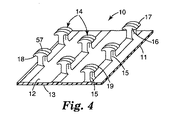
図4は、本発明の方法に従って製造することができる代表的な前駆体ポリマーフックファスナー部分の拡大透視図であり、一般的に参照数字10によって示す。フックファスナー部分10は、略平行な上部および下部主面12および13を有する薄くて強い可撓性のフィルム様バッキング11と、バッキング11の少なくとも上部表面12から突出している離間した複数のフック部材14とを含む。耐引裂性または補強性に関して望まれる場合には、バッキングは平らな表面または表面特徴を有し得る。フック部材14は、それぞれ、バッキング11の一端に取り付けられ、そしてバッキング11との接合部においてフックの固定および破壊強さを向上させるために好ましくはバッキング11に向かって広がるテーパ部分を有するステム部分15と、バッキング11の反対側のステム部分15の端部のヘッド部分17とを含む。ヘッド部分17の側部16は、片側または2つの対向する側部でステム部分15の側面と同一平面であり得る。ヘッド部分17は、ステム部分の片側または両側でステム部分を越えて突出しているフック固定部分またはアーム19を有する。図示したフック部材は、ループファスナー部分のループ間にヘッド部分17が入ることを助けるようにステム部分15の反対側に丸みを帯びた表面を有する。またヘッド部分17は、バッキング11上に突出しているステム部分15とヘッド部分17の表面との間の接合部に、横断する円筒形の凹形表面部分を有する。
FIG. 4 is an enlarged perspective view of an exemplary precursor polymer hook fastener portion that can be manufactured according to the method of the present invention and is generally indicated by
またフック部材14は、隣接する同一の広がりを有するフックヘッド要素18を生じるフックヘッド部分17を二分する第2の切れ目57を有する。示されるように第2の切れ目は、フック部分17を通して、そしてステム部分15中まで延在する。しかしながら、第2の切れ目はバッキング11の上部表面12までは延在しない。一般的に、第2の切れ目は第1の切れ目59の末端エッジ部の少なくとも約0.1mm上、好ましくは少なくとも0.2mm上で終わる。これによって、縦方向で延在する場合、第2の切れ目においてリブを分離することなく、前駆体フックファスナーが第1の切れ目において好ましく分離される。未分離および/または未分化のフックヘッド要素18は、分離または分化されたフックヘッド要素の前駆体を形成する。
The
フックファスナー部分10の形成に続いて、フックファスナー部分を、フックヘッド要素18の分離および/または分化を引き起こす処理にかけることができる。これを図5Aに示す。フックファスナー部分20のバッキング11は、略平行な上部および下部主面12および13、ならびにバッキング11の少なくとも上部表面12から突出している離間した複数のフック部材24を有する。耐引裂性または補強性に関して望まれる場合には、バッキングは平らな表面または表面特徴を有し得る。フック部材24は、それぞれ、バッキング11に一端に取り付けられたステム部分25を含む。バッキング11の反対側のステム部分25の端部のヘッド部分は、第2のカット線27に沿って2つの別個のフックヘッド要素28および29へと分離および/または分化されている。フックヘッド要素28および29の側部は、片側または2つの対向する側部でステム部分25の側面と同一平面であり得る。フックヘッド要素28および29は、ステム部分の片側または両側でステム部分25を越えて突出しているフック固定部分またはアームを有する。図示したフック部材は、ループファスナー部分のループ間にフックヘッド要素が入ることを助けるようにステム部分25の反対側に丸みを帯びた表面を有する。またフックヘッド要素28および29は、1以上の方向で互いから広がるアームを有する。分離および/または分化されたフックヘッド要素28および29は、それぞれ、ループ繊維を独立して係合することができる別々のフック要素またはアームを有する。
Following formation of the
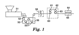
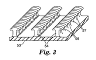
図4および図5Aのようなフックファスナー部分を形成するための方法の第1の実施形態を、図1に図示する。一般的に、この方法は、ベース53と、形成されるフック部分または部材の断面形状を有するベース層53の上部表面上に突出している細長い離間したリブ54とを有するストリップ50を形成するために、例えば、放電機械加工によって成形された開口カットを有するダイ52を通して、押出機51から熱可塑性樹脂の図2に示されるストリップ50をまず押出する工程を含む。冷却液(例えば水)で充填したクエンチタンク56を通して、ローラー55を回って、ストリップ50を引き、その後、リブ54(ベース層53でなく)は、それらの長手方向に沿って離間した第1および第2の位置で一連のカッター58によって横方向にスリッティング又は切断されて、図3に示されるように形成される前駆体フック部分のほぼ所望の厚さに相当する間隔を有するリブ54の第1の切れ目部分59を形成する。この切れ目は、リブの縦の延在方向から、おおよそ90°〜30°のいずれかの所望の角度であり得る。リブを形成するポリマーにさらなる分子配向を提供するため、及び/またはリブの大きさを減少してリブのスリッティングによって形成されたフック部材を小さくするために、切れ目を入れる前に、必要に応じてストリップを延伸することができる。レシプロ式または回転式ブレード、レーザーまたはウォータージェットのような従来の手段のいずれかを使用してカッター58により切断することができるが、しかしながら好ましくは、リブ54の縦の延在方向に対して約60°〜80°の角度で配向されたブレードを使用して切れ目を入れる。第2のカッターによって、切れ目線57で、第1の切れ目59の深さ未満のあらかじめ決められた深さまでリブに切れ目を入れる。一般的に、リブをその後延伸してフック部材を形成する時にフック部材が均一にあらかじめ決められた配列で形成されるように、全ての第1の切れ目は実質的に同じあらかじめ決められた深さで提供される。しかしながら、不連続なあらかじめ決められたフック部材の形成を可能にするあらかじめ決められた距離までストリップが延伸される時に、切れ目線に沿って分離を生じないようにそれらが提供される限り、第2の切れ目の深さが均一である必要はない。
A first embodiment of a method for forming a hook fastener portion as in FIGS. 4 and 5A is illustrated in FIG. Generally, this method is used to form a
リブ54に切れ目を入れた後、好ましくは異なる表面速度で運転される第1の対のニップローラー60および61と第2の対のニップローラー62および63との間で、ストリップ50のベース53を少なくとも2:1の延伸比で、好ましくは約4:1の延伸比で縦方向に延伸する。これによって、第2の切れ目線57が影響を受けないままで、切れ目が入れられたリブが好ましく第1の切れ目線59で分離される。しかしながら、十分な程度まで延伸することによって、1以上の第2の切れ目線57の間でベースを伸長することもできる。任意に、ベース53に二軸配向をもたらすようにストリップ50を横方向に延伸することもできる。これによって、ベースをより薄くおよびより可撓性にするとともにフック要素の密度を減少させることができる。延伸前に、ベース53を加熱するためにローラー61が加熱されていることが好ましく、そして延伸されたベース53を安定化するためにローラー62が冷却されていることが好ましい。最初に延伸することによって、リブ54の第1の切れ目部分59の間に空間が形成されて、次いで、これは完成したフックファスナー部分10のフック部または部材14となる。次いで、第2の切れ目線によって形成されるフックヘッド要素の分化および/または分離を引き起こすために、形成されたフック部材を処理してもよい。この処理は、好ましくは熱処理であり得、好ましくは非接触熱源64による。加熱の温度および期間は、5%〜90%まで少なくともヘッド部分の収縮または厚さ減少を引き起こすように選択されるべきであり、これによって、フックヘッド要素18の分化および/または分離も引き起こされる。好ましくは、放射点、予熱空気、炎、UV、マイクロ波、超音波または集束IR熱ランプを含み得る非接触加熱源を使用して加熱を達成する。この熱処理は、形成されたフック部材を含むストリップ全体にわたって可能であるが、ストリップの一部分または一領域のみに対しても可能である。またはストリップの異なる部分を、処理の程度に差をつけて熱処理することができる。この様式では、異なる成形リブプロファイルを押出する必要なく、性能レベルが異なる領域を含むフックを単一ストリップ上に得ることが可能である。この熱処理によって、フックストリップの領域にわたって連続的にまたは勾配をつけてフック要素を変更、分離および/または分化することが可能である。この様式では、分化および/または分離されたフック要素は、フック部材の画定された領域にわたって連続的に異なり得る。さらにフック密度は、実質的に同一のフィルムバッキングカリパスまたは厚さ(例えば、50ミクロン〜500ミクロン)と連結された異なる領域で同一であり得る。異なるフック厚を有するフック要素または部材のような異なる種類のフック部材または要素を、フックストリップの縦方向で単一列または多列で得ることができるように、熱処理は、異なる列に沿って可能であるか、または異なる列を横切ることが可能である。基本フック要素製造プロセスの変更を必要とせずに、カスタマイズされた性能を生じることができるように、フック要素の作製に続くいずれの時間でも熱処理を実行することができる。
After cutting the
図5Aは、少なくともフックヘッド部分の厚さの減少、ならびに分離および/または分化されたフックヘッド要素28および29へのフックヘッド要素18の分化および分離を引き起こすように熱処理された後の図4のフックファスナー部分のフックファスナー部分を示す。これによって一般的に、例えば、様々な分化および/または分離されたフックヘッド要素28が28’、29’、28’’、29’’、28’’’および29’’’と示される図5B、5Cおよび5Dに示されるように、例えば、異なる量のアーム状の垂れ下がり(arm droop)またはカールを有することによって少なくともわずかに互いから分岐し得る分化および/または分離されたフックヘッド要素が得られる。一般的に質量保存の法則の結果として、フック部材14およびフックヘッド要素18の他の寸法も変更可能である。フックヘッド要素28および29のアームは、同一の広がりを有し得るか、またはフック部材の高さ平面で、もしくはフック部材の高さ平面からわずかに分岐する。フック部材の高さは一般的にわずかな量で増加し、そしてヘッド部分の幅は、アーム状の垂れ下がりの増大とともに増加する。ステムおよびヘッド部分は、全フック部材14に沿って不完全な熱処理のためにベースからヘッド部分まで不均な厚さ寸法およびテーパーを有し得る。一般的に未処理の部分は、最初の厚さと一致する均一な厚さを有し、一般的に完全に熱処理された部分は、均一な厚さを有し、移行領域が未処理の部分と処理された部分とを分離する。また不完全な熱処理は、フック要素アーム先端からステムに隣接するアーム部分までフックヘッド部分の厚さの変化を生じ得る。
FIG. 5A is the view of FIG. The hook fastener part of a hook fastener part is shown. This is generally illustrated, for example, in FIG. 5B in which various differentiated and / or separated
フック部材の厚さの減少は、一般的に厚さ方向と一致する縦方向のフックヘッドおよび/またはステム部分の少なくとも溶融流動によって誘発された分子配向の緩和によって引き起こされる。また、切れ目を入れる前にリブを縦方向に延伸する時に延伸によって誘発された分子配向がある場合、厚さのさらなる減少が起こり得る。溶融によって誘発された分子配向は、圧力および剪断力下でダイオリフィス中にポリマーを強制的に通過させる時に、溶融押出プロセスによって生じる。ダイのリブまたはリッジ形成セクションは、形成リブに分子配向を生じる。この分子配向は、リブまたはリッジに沿って縦方向に広がる。リブまたはリッジに切れ目を入れる時、分子配向は、切れ目が入れられたリブまたは切れ目が入れられたフック部材の厚さ方向に概して広がるが、分子配向はフック部材の厚さ方向に対して約0度〜45度の角度を成して広げることができる。フック部材中の初期の分子配向は、一般的に、少なくとも10%、好ましくは20%〜100%である(以下の試験法の項目で定義される通り)。本発明に従ってフック部材を熱処理する場合、フック部材の分子配向は減少し、そしてフック部材の厚さ寸法は減少する。厚さ減少量は、縦方向に延在するフック部材の分子配向量またはフック厚さ寸法に主に依存する。処理時間、温度、熱源の特性等のような熱処理条件も、フック部材の厚さ減少をもたらし得る。熱処理が進行するにつれて、フック部材全体の厚さが減少するまで、フック部材における縮小または突出部の厚さの減少が、フックヘッド部分または突出部のトップからステム部分までまたは突出部の下方のベースまで広がる。一般的に、両者とも完全に熱処理されるか、または同一範囲まで部分的に熱処理される場合、ステムおよびフックヘッド部分において、厚さ減少は実質的に同一である。フックヘッド部分の一部分のみおよび/またはフックヘッド部分およびステム部分が熱処理される場合、上部熱処理部分、一般的にヘッド部分から、ステム部分の実質的に熱処理されない部分、またはステム部分および実質的に減少していない厚さを有するフックヘッド部分の一部分まで厚さが増加する移行領域が存在する。厚さ寸法が収縮する場合、処理部分の幅は一般的に増加し、一方、全フック部材の高さはわずかに増加し、アーム状の垂れ下がりは増加する。この結果、経済的に直接製造できないか、または従来法によっては全く製造することができないフック厚さがもたらされる。熱処理された突出部、一般的にはフックヘッド、場合によりステムは、10%未満、好ましくは5%未満の分子配向度により特徴付けられ、ベースフィルム層の配向は実質的に減少しない。一般的に、ベースフィルム層に隣接するフック部材ステムまたは突出部の配向度は、10%以上、好ましくは20%以上である。 The reduction in hook member thickness is caused by relaxation of molecular orientation induced by at least melt flow of the longitudinal hook head and / or stem portion, generally coincident with the thickness direction. Also, if there is molecular orientation induced by stretching when the rib is stretched longitudinally before making a cut, further reduction in thickness can occur. Molten induced molecular orientation is caused by the melt extrusion process when the polymer is forced through a die orifice under pressure and shear. The rib or ridge forming section of the die creates molecular orientation in the forming rib. This molecular orientation extends longitudinally along the rib or ridge. When a cut is made in a rib or ridge, the molecular orientation generally extends in the thickness direction of the cut rib or hook member, but the molecular orientation is about 0 relative to the thickness direction of the hook member. It can be spread at an angle of ~ 45 degrees. The initial molecular orientation in the hook member is generally at least 10%, preferably 20% to 100% (as defined in the test method section below). When heat treating a hook member in accordance with the present invention, the molecular orientation of the hook member is reduced and the thickness dimension of the hook member is reduced. The amount of thickness reduction mainly depends on the molecular orientation amount of the hook member extending in the longitudinal direction or the hook thickness dimension. Heat treatment conditions such as processing time, temperature, heat source characteristics, etc. can also result in a reduction in hook member thickness. As the heat treatment progresses, the hook member shrinks or the protrusion thickness decreases until the entire hook member thickness decreases, either from the top of the hook head or protrusion to the stem portion or below the protrusion. Spread to. Generally, when both are fully heat treated or partially heat treated to the same extent, the thickness reduction is substantially the same in the stem and hook head portions. If only a portion of the hook head portion and / or the hook head portion and the stem portion are heat treated, the upper heat treated portion, generally from the head portion, the substantially unheated portion of the stem portion, or the stem portion and substantially reduced. There is a transition region where the thickness increases to a portion of the hook head portion having a thickness that is not. As the thickness dimension shrinks, the width of the treated portion generally increases, while the height of all hook members increases slightly and the arm-like sag increases. This results in a hook thickness that cannot be manufactured directly economically or at all by conventional methods. Heat treated protrusions, typically hook heads, and possibly stems, are characterized by a degree of molecular orientation of less than 10%, preferably less than 5%, and the orientation of the base film layer is not substantially reduced. Generally, the degree of orientation of the hook member stem or protrusion adjacent to the base film layer is 10% or more, preferably 20% or more.
熱処理は、一般的に、ポリマー溶融温度付近またはそれより上の温度で行われる。その熱によって、ポリマーの溶融温度より著しく高くなる場合、フックヘッド部分または突出部のトップにおけるポリマーのいかなる実際の溶融も最低限に抑えるために、処理時間を短くする。熱処理は、フックヘッドおよび/またはステムの厚さの減少をもたらすのに十分な時間で行われるが、バッキングの著しい変形またはフックヘッド部分もしくは突出部のトップの溶融流動が起こらないようにする。また熱処理は、フックヘッド部分のエッジを丸める結果をもたらし、衣服用途における使用に関して触感を改善し得る。 The heat treatment is generally performed at a temperature near or above the polymer melting temperature. If the heat is significantly higher than the melting temperature of the polymer, the processing time is shortened to minimize any actual melting of the polymer at the top of the hook head portion or protrusion. The heat treatment is performed for a time sufficient to result in a reduction in hook head and / or stem thickness, but prevents significant deformation of the backing or melt flow of the top of the hook head portion or protrusion. Heat treatment can also result in rounding the edges of the hook head portion and can improve tactile feel for use in garment applications.
一般的に、本発明の方法における使用に好適なフック部材は、処理前および後の両方において、5000μm未満のバッキングの上部表面からの高さ寸法を有する。ステムおよびヘッド部分は、一般的に、バッキングの表面と平行な第1の方向で1500μm未満の厚さ寸法を有する。ステム部分は、それぞれ、一般的に第1の方向に対して直角およびバッキングの表面に対して平行で、第2の方向において50μm〜500μmの範囲の幅寸法を有し、そしてヘッド部分は、それぞれ、ステム部分の幅寸法より大きい50μmと2000μmとの間である第2の方向において幅寸法を有し、そして全体的な幅は5000μm未満である。一般的に、ベースの1平方センチメートルあたり、少なくとも10、好ましくは20〜200、または20〜300のフック部材が存在する。 In general, hook members suitable for use in the method of the present invention have a height dimension from the upper surface of the backing of less than 5000 μm, both before and after processing. The stem and head portions generally have a thickness dimension of less than 1500 μm in a first direction parallel to the surface of the backing. The stem portions are each generally perpendicular to the first direction and parallel to the backing surface, have a width dimension in the second direction ranging from 50 μm to 500 μm, and the head portions are each Having a width dimension in a second direction that is between 50 μm and 2000 μm, greater than the width dimension of the stem portion, and the overall width is less than 5000 μm. Generally, there are at least 10, preferably 20-200, or 20-300 hook members per square centimeter of base.
本発明の方法によって製造できる特に好ましい新規マイクロフック部材は、1000μm未満、好ましくは300μm〜800μmの高さを有し、そして少なくともフックヘッド要素部分が50μm〜200μm、好ましくは50μm〜180μmの厚さを有するフック部材である。この改善されたマイクロフックの他の寸法は、上記で定義されるように、50μm〜500μmのステム幅、100μm〜800μmのヘッド部分幅、および50μm〜700μm、好ましくは100μm〜500μmのフック要素のためのアーム状の垂れ下がり、および1平方センチメートルあたり少なくとも50、そして好ましくは約70〜150、300までのフックのフック部材密度を含む。この新規マイクロフックは、改善された全体的性能を様々な低ロフトループ布に対して示す。 Particularly preferred novel microhook members that can be produced by the method of the present invention have a height of less than 1000 μm, preferably 300 μm to 800 μm, and at least the hook head element portion has a thickness of 50 μm to 200 μm, preferably 50 μm to 180 μm. It is a hook member which has. Other dimensions of this improved microhook are for stem elements of 50 μm to 500 μm, head portion widths of 100 μm to 800 μm, and hook elements of 50 μm to 700 μm, preferably 100 μm to 500 μm, as defined above. Arm hooks and a hook member density of at least 50 and preferably from about 70 to 150,300 hooks per square centimeter. This new microhook demonstrates improved overall performance for various low loft loop fabrics.
フックファスナー部分を製造することができる適切なポリマー材料としては、ポリオレフィン、例えばポリプロピレンおよびポリエチレン、ポリ塩化ビニル、ポリスチレン、ナイロン、ポリエチレンテレフタレート等のようなポリエステルを含む熱可塑性樹脂、ならびにそのコポリマーおよびブレンドが挙げられる。好ましくは、樹脂は、ポリプロピレン、ポリエチレン、ポリプロピレン−ポリエチレンコポリマーまたはそのブレンドである。 Suitable polymeric materials from which the hook fastener portion can be made include thermoplastics including polyolefins such as polypropylene and polyethylene, polyvinyl chloride, polystyrene, nylon, polyethylene terephthalate, and the like, and copolymers and blends thereof. Can be mentioned. Preferably, the resin is polypropylene, polyethylene, polypropylene-polyethylene copolymer or blends thereof.
ファスナーのバッキングは、音波溶接、熱結着、裁縫、または感圧接着剤もしくはホットメルト接着剤を含む接着剤のような所望の手段によって基材に結合され、そしてしっかりとステムを固定し、ファスナーが剥離される時に引裂き抵抗を示すように十分厚くなければならない。しかしながら、ファスナーが使い捨て衣服上で使用される場合、バッキングは、必要とされるよりも剛くなるような厚さであってはならない。一般的にバッキングは、それ自体で、または使い捨て吸収性物品に使用されるための同様に軟質であるべき不織物、織物もしくはフィルム型バッキングのようなさらなるキャリアバッキング構造に積層化されて、使用時に柔軟であると認められるように、10〜2000、好ましくは10〜200のガーレー剛度(Gurley stiffness)を有する。最適バッキング厚さは、フックファスナー部分が製造される樹脂に依存して異なるが、一般的に20μmと1000μmとの間である。 The fastener backing is bonded to the substrate by any desired means such as sonic welding, thermal bonding, sewing, or adhesives including pressure sensitive adhesives or hot melt adhesives, and securely fastens the stem and fasteners It must be thick enough to exhibit tear resistance when peeled off. However, if the fastener is used on a disposable garment, the backing should not be so thick that it is stiffer than needed. Generally the backing is laminated on its own or in a further carrier backing structure, such as a non-woven, woven or film-type backing, that should also be soft for use in disposable absorbent articles, and in use. It has a Gurley stiffness of 10 to 2000, preferably 10 to 200 so as to be recognized as flexible. The optimum backing thickness varies depending on the resin from which the hook fastener portion is manufactured, but is generally between 20 and 1000 μm.
図6は、本発明に従って製造することができるポリマーフックファスナー部分の第2の実施形態である。フックファスナー部分30のバッキング11は、略平行な上部および下部の主要表面12および13、ならびにバッキング11の少なくとも上部表面12から突出している複数の離間したフック部材39を有する。フック部材39は、それぞれ、バッキングへの一端に結合されたステム部分と、バッキング11の反対側のステム部分の端部にヘッド部分とを含む。ヘッド部分34は、異なる幅の別の第1の切れ目と、あるいはより広いフック部材の第2の切れ目とによって生じる2つの異なる幅のものである。この実施形態において、分化によって、第2の切れ目を有し複数のフックヘッド要素を有するフック部材と、1つのフックヘッド要素を有する他のフック部材とが生じる。
FIG. 6 is a second embodiment of a polymer hook fastener portion that can be manufactured in accordance with the present invention. The backing 11 of the
図7は、本発明に従って製造することができる前駆体ポリマーフックファスナー部分の第3の実施形態である。フックファスナー部分40のバッキング11は、略平行な上部および下部の主要表面12および13、ならびにバッキング11の少なくとも上部表面12から突出している複数の離間したフック部材48を有する。この実施形態において、それぞれのフック部材はフックヘッド部分およびステム部分を含むが、ただし2つの第2のカットを条件とする。ヘッド部分が分化および/または分離される場合、フックヘッド部分は、第2のカット57によって分離された3つの別々のフックヘッド要素を形成する。それぞれのフックヘッド要素は、ステム部分の一方または両方でステム部分を越えて突出している別々のフック係合部分またはアームを有する。
FIG. 7 is a third embodiment of a precursor polymer hook fastener portion that can be manufactured in accordance with the present invention. The backing 11 of the
フック部材のフック要素は、ステム部分と比較して好ましくは相対的に薄く、フック要素の平均厚さのステム部分の平均厚さに対する比率は、一般的に0.1〜0.9、好ましくは0.25〜0.5であり得、フックヘッド要素の厚さは、50μm〜1000μm、好ましくは50μm〜400μmである。これによって、極めて薄いフックヘッドが著しく大きいステム構造上に確実に支持され、そして容易に変形するか、または壊れる可能性のある薄いステムに対する懸念を減少する。なお低ロフトの安価な不織布を係合可能でありながら、より頑強な適用におけるフックの使用を可能にする。単一方向における複数のフックヘッド要素の供給も、繰り返される使用における機能性を増加させる。フックヘッド要素が機能しなくなる場合、例えば、変形または破損された場合、第2または可能なさらなるフックヘッド要素は、同一フック部材上でループ繊維を係合するために利用可能である。これによって、長期使用性能および耐久性が増加する。 The hook element of the hook member is preferably relatively thin compared to the stem portion, and the ratio of the average thickness of the hook element to the average thickness of the stem portion is generally 0.1 to 0.9, preferably The thickness of the hook head element can be between 0.25 and 0.5 and is between 50 μm and 1000 μm, preferably between 50 μm and 400 μm. This ensures that a very thin hook head is supported on a significantly larger stem structure and reduces concerns for thin stems that can easily deform or break. It allows the use of hooks in more robust applications while being able to engage low-loft, inexpensive non-woven fabrics. The provision of multiple hook head elements in a single direction also increases functionality in repeated use. If the hook head element fails, for example if it is deformed or broken, a second or possible further hook head element is available for engaging the loop fibers on the same hook member. This increases long-term use performance and durability.
試験方法
135°剥離試験
135度剥離試験を使用して、ループファスナー材料の試料からフックファスナーウェブの試料を剥離するために必要とされる力の量を測定した。両面接着テープを使用して5.1cm×12.7cmのループ試験材料片を5.1cm×12.7cm鋼パネル上にしっかり配置した。パネルの長手方向にループ材料の横方向が平行になるように、ループ材料をパネル上に配置した。試験すべきフックファスナーの1.9cm×2.5cmストリップを、長い方の寸法がウェブの縦方向にあるように切断した。幅2.5cmのペーパーリーダーを、フックストリップの一端の平滑な側に取り付けた。次いで、ストリップとループ材料との間に1.9cm×2.5cmの接触領域があり、そしてストリップのリーディングエッジがパネルに沿ってあるように、フックストリップをループの中央に配置した。次いで、ストリップとループ材料の積層体をそれぞれの方向に2回ずつ、1分あたり約30.5cmの速度で1000グラムローラーを使用して手でローラーにかけた。次いで、試料を135度剥離ジグに置いた。インストロン(Instron)(登録商標)モデル1122引張試験機の底部ジョーにジグを入れた。ペーパーリーダーの解放端部を引張試験機の上部ジョーに置いた。1分あたり30.5cmのクロスヘッド速度および1分あたり50.8cmのチャート速度に設定されたチャートレコーダーを使用して、フックストリップが135度の一定の角度でループ材料から剥離される時の剥離力を記録した。4つの最高ピークの平均をグラム単位で記録した。フックファスナーストリップをループ材料から除去するために必要とされる力は、グラム/2.54cm幅で記録した。最低10回の試験を実行し、そしてそれぞれのフックとループの組合せに関して平均した。ループ試験材料は、3M カンパニー(3M Company)からKN−1971として入手可能な米国特許第5,616,394号明細書の実施例1に記載のものと同様に製造された不織ループであった。ループ試験材料は、いくつかの回転の巻き戻しおよび廃棄後、材料の供給ロールから得られ、「新しい」材料に暴露された。そのようにして得られた試験材料は相対的に圧縮された状態にあり、そしてループのいずれかの重要な再ロフトが生じる前に直ちに剥離試験に使用した。
Test Method 135 Degree Peel Test The 135 degree peel test was used to measure the amount of force required to peel a hook fastener web sample from a sample of loop fastener material. A 5.1 cm × 12.7 cm piece of loop test material was securely placed on a 5.1 cm × 12.7 cm steel panel using double-sided adhesive tape. The loop material was placed on the panel so that the transverse direction of the loop material was parallel to the longitudinal direction of the panel. A 1.9 cm x 2.5 cm strip of hook fastener to be tested was cut so that the longer dimension was in the machine direction of the web. A 2.5 cm wide paper leader was attached to the smooth side of one end of the hook strip. The hook strip was then placed in the center of the loop so that there was a 1.9 cm x 2.5 cm contact area between the strip and the loop material and the leading edge of the strip was along the panel. The laminate of strip and loop material was then hand rolled using a 1000 gram roller at a rate of about 30.5 cm per minute, twice in each direction. The sample was then placed on a 135 degree peel jig. A jig was placed in the bottom jaw of an Instron® Model 1122 tensile tester. The open end of the paper leader was placed on the upper jaw of the tensile tester. Peeling when the hook strip is peeled from the loop material at a constant angle of 135 degrees using a chart recorder set at a crosshead speed of 30.5 cm per minute and a chart speed of 50.8 cm per minute The power was recorded. The average of the four highest peaks was recorded in grams. The force required to remove the hook fastener strip from the loop material was recorded in grams / 2.54 cm width. A minimum of 10 tests were performed and averaged for each hook and loop combination. The loop test material was a nonwoven loop made similar to that described in Example 1 of US Pat. No. 5,616,394 available as KN-1971 from the 3M Company. . The loop test material was obtained from the material supply roll after several revolutions of unwinding and disposal and was exposed to the “new” material. The test material so obtained was in a relatively compressed state and was used immediately in the peel test before any significant reloft of the loop occurred.
135°ツイスト剥離試験
135度剥離試験を使用して、低プロフィールループファスナー材料の試料からフックファスナーウェブの試料を剥離するために必要とされる力の量を測定した。試験すべきフックファスナーウェブの1.9cm×2.5cmのストリップは、長い方の寸法がウェブの縦方向にあるように切断した。幅2.5cmのペーパーリーダーを、フックストリップの一端の平滑な側に取り付けた。以下の手順を使用して、フック材料を低プロファイルループ材料に固定した:フック側を低くして、おしめの低プロフィールループバックシート材料上にフック材料を配置した。4.1kg重量の、低部表面上の7.6cm×7.6cm幅の中間グリット吸収ペーパーをフック材料のトップに配置した。フックとバックシートループ材料とを係合するために、おしめを確実に平坦な状態に保持し、そして重量を右に45度、次いで左に90度、次いで右に90度、次いで左に45度ねじった。次いで重量を除去して、そしてインストロン(Instron)(登録商標)モデル1122引張試験機の下部ジョー中に設置された135度のジグスタンドの表面に対してしっかりとおむつを保持した。フック材料に取り付けられたペーパーリーダーの解放端部を引張試験機の上部ジョーに置いた。1分あたり30.5cmのクロスヘッド速度および1分あたり50.8cmのチャート速度に設定されたチャートレコーダーを使用して、フックストリップが135度の一定の角度でループ材料から剥離される時の剥離力を記録した。4つの最高ピークの平均をグラム単位で記録し、グラム/2.54cm幅で報告した。それぞれのおむつで10の異なる位置を試験し、そして10回の平均を表4に報告した。ループ試験材料は、プロクター アンド ギャンブル パンパース(Procter & Gamble Pampers)おむつサイズ4のバックシートの不織側(すなわち、外側に面する側)であった。
135 ° Twist Peel Test A 135 degree peel test was used to measure the amount of force required to peel a sample of hook fastener web from a sample of low profile loop fastener material. A 1.9 cm x 2.5 cm strip of hook fastener web to be tested was cut so that the longer dimension was in the machine direction of the web. A 2.5 cm wide paper leader was attached to the smooth side of one end of the hook strip. The following procedure was used to secure the hook material to the low profile loop material: the hook material was placed on the diaper low profile loop backsheet material with the hook side lowered. A 4.1 kg weight of a 7.6 cm × 7.6 cm wide intermediate grit absorbent paper on the lower surface was placed on top of the hook material. To engage the hook and backsheet loop material, ensure that the diaper is held flat and weigh 45 degrees to the right, then 90 degrees to the left, then 90 degrees to the right, then 45 degrees to the left Twisted. The weight was then removed and the diaper was held firmly against the surface of a 135 degree jigstand placed in the lower jaw of an Instron® model 1122 tensile tester. The open end of the paper leader attached to the hook material was placed on the upper jaw of the tensile tester. Peeling when the hook strip is peeled from the loop material at a constant angle of 135 degrees using a chart recorder set at a crosshead speed of 30.5 cm per minute and a chart speed of 50.8 cm per minute The power was recorded. The average of the four highest peaks was recorded in grams and reported in grams / 2.54 cm width. Ten different positions were tested in each diaper and the average of 10 times was reported in Table 4. The loop test material was the non-woven side (ie, the outward facing side) of a Procter & Gamble Pampers diaper size 4 backsheet.
動的剪断
ダイナミック剪断試験を使用して、ループファスナー材料の試料から機械ファスナーフック材料の試料を剪断するために必要とされる力の量を測定した。剪断試験を実行するために、135度剥離試験に関して上記されたものと同一のループ材料を使用した。2.5cm×7.5cmループ試料は、短い方の寸法がフックの縦方向であるようにカットされた。次いで、3Mストラッピングテープによってループの裏面でこのループ試料を強化した。1.25cm×2.5cmフック試料も調製した。長い方の寸法はフックの縦方向である。この試料を、3Mストラッピングテープの幅2.5cm×長さ7.5cmのタブの端部に積層した。接着剤をカバーするために、フックなしで末端でそれ自体の上に、ストラッピングテープを二重にした。次いで、長いタブ方向が互いに平行であるようにループの中央にフックを配置し、ループタブが第1の端部で越えて延在し、そしてフックタブが第2の端部で越えて延在した。5kgロールダウンによって手でフックをロールダウンし、5回繰返した。インストロン(Instron)(登録商標)モデル1122引張試験機のジョー中に、アセンブルされたタブを配置した。フックタブを上部ジョーに配置し、そしてループタブを底部ジョーに配置した。1分あたり30.5cmのクロスヘッド速度および1分あたり50.8cmのチャート速度に設定されたチャートレコーダーを使用して、フックストリップが180度の一定の角度でループ材料から剪断される時の剪断力を記録した。最大荷重をグラム単位で記録した。ループ材料から機械ファスナーストリップを剪断するために必要とされる力をグラム/2.54cm幅で報告した。最低10回の試験を実行し、そしてそれぞれのフックおよびループ組合せに関して平均した。
Dynamic Shear The dynamic shear test was used to measure the amount of force required to shear a sample of mechanical fastener hook material from a sample of loop fastener material. To perform the shear test, the same loop material as described above for the 135 degree peel test was used. The 2.5 cm × 7.5 cm loop sample was cut so that the shorter dimension was the longitudinal direction of the hook. The loop sample was then reinforced on the back side of the loop with 3M strapping tape. A 1.25 cm × 2.5 cm hook sample was also prepared. The longer dimension is the vertical direction of the hook. This sample was laminated to the end of a 3M strapping tape width 2.5 cm x length 7.5 cm tab. To cover the adhesive, the strapping tape was doubled on itself at the end without a hook. The hook was then placed in the center of the loop so that the long tab directions were parallel to each other, the loop tab extending beyond the first end, and the hook tab extending beyond the second end. The hook was rolled down by hand with a 5 kg roll down and repeated 5 times. The assembled tab was placed in the jaw of an Instron® model 1122 tensile tester. A hook tab was placed on the top jaw and a loop tab was placed on the bottom jaw. Shear when the hook strip is sheared from the loop material at a constant angle of 180 degrees using a chart recorder set at a crosshead speed of 30.5 cm per minute and a chart speed of 50.8 cm per minute The power was recorded. Maximum load was recorded in grams. The force required to shear the mechanical fastener strip from the loop material was reported in grams / 2.54 cm width. A minimum of 10 tests were performed and averaged for each hook and loop combination.
フック寸法
約25倍率のズームレンズを備えたライカ(Leica)顕微鏡を使用して、実施例フック材料の寸法を測定した。試料を、x−y可動ステージに配置し、そして最も近いミクロンまでステージ移動を通して測定した。最低3回の繰り返しを使用して、それぞれの寸法の平均とした。
Hook Dimensions The dimensions of the example hook material were measured using a Leica microscope equipped with a zoom lens with a magnification of about 25 ×. Samples were placed on an xy movable stage and measured through stage movement to the nearest micron. A minimum of 3 repetitions was used to average each dimension.
分子配向
X線回折技術を使用して、実施例フック材料の配向度を測定した。銅のKα放射線を使用するブルカー(Bruker)微小拡散計(ブルカー(Bruker)AXS、ウィスコンシン州、マディソン(Madison,Wisconsin))、および散乱放射線のハイスター(HiSTAR)(登録商標)二次元検出器レジストリーを使用してデータを集めた。回折計に、グラファイト入射ビーム光線モノクロメーターおよび200マイクロメートルピンホールコリメータが付いていた。X線源は、50キロボルト(kV)および100ミリアンペア(mA)で操作されたアノードおよび銅ターゲットを回転させるリガク(Rigaku)RU200(リガク(Rigaku)USA、マサチューセッツ州、ダンバーズ(Danvers,MA))から成った。0度(2θ)で中心に配置された検出器を有し、試料から検出器までの距離が6cmであるトランスミッションジオメトリーにおいてデータを集めた。フックアームを外した後に縦方向でフック材料の薄い断面を切断することによって、試験片を得た。入射ビームは、切断された断面の平面に垂直であり、従って押出ウェブの横方向に平行だった。レーザーポインターおよびデジタルビデオカメラ配置システムを使用して、3つの異なる位置を測定した。ヘッド部分の中心付近で、ステム部分の中央点の付近で、そしてバッキングのわずかに上のステム部分の可能な限り低部付近で、測定を行った。ガッドス(GADDS)(登録商標)ソフトウェア(ブルカー(Bruker)AXS(ウィスコンシン州、マディソン(Madison,Wisconsin))を使用して、データを3600秒に関して累積し、そして検出器の感度および空間線形に関して修正した。6〜32度(2θ)散乱角範囲内の結晶ピークの面積と全ピークの面積(結晶+非晶質)との比率として、結晶化度を計算した。1の値は100%結晶化度を表し、そしてゼロの値は完全に非晶質材料(0%結晶度)と一致する。分子配向度(%)は、二次元の回折データのラジアルトレースから計算された。バックグラウンドおよび非晶質強度は、以下で定義されるトレース(A)および(C)によって定義される2θ位置間で直線状であると仮定された。トレース(B)におけるバックグラウンドおよび非晶質強度をそれぞれの要素に対して補間し、トレースから引き算して、(B’)を得た。トレース(B’)のプロットは、配向がない場合は一定強度を有し、そして好ましい配向が存在する場合は振動強度パターンを有する。好ましい配向を有さない結晶フラクションの大きさは、振動パターンの最低限度によって定義される。配向された結晶フラクションの大きさは、振動パターンの最低限度を超過する強度によって定義される。配向度(%)は、トレース(B’)から個々の成分の積分によって計算した。
Molecular orientation The degree of orientation of the Example hook material was measured using X-ray diffraction techniques. Bruker of using K alpha radiation of copper (Bruker) small diffusion gauge (Bruker (Bruker) AXS, Madison, WI (Madison, Wisconsin)), and the scattered radiation of the high-Star (HiStar) (TM) two-dimensional detector Data was collected using the registry. The diffractometer was equipped with a graphite incident beam ray monochromator and a 200 micrometer pinhole collimator. The X-ray source is from Rigaku RU200 (Rigaku USA, Danvers, Mass.), Which rotates an anode and copper target operated at 50 kilovolts (kV) and 100 milliamps (mA). Made. Data were collected in a transmission geometry with a detector centered at 0 degrees (2θ) and a 6 cm distance from the sample to the detector. A specimen was obtained by cutting a thin section of the hook material in the longitudinal direction after removing the hook arm. The incident beam was perpendicular to the plane of the cut section and was therefore parallel to the lateral direction of the extruded web. Three different positions were measured using a laser pointer and digital video camera placement system. Measurements were taken near the center of the head part, near the center point of the stem part, and as low as possible on the stem part slightly above the backing. Using GADDS® software (Bruker AXS (Madison, Wisconsin), Wisconsin), data was accumulated for 3600 seconds and corrected for detector sensitivity and spatial alignment The crystallinity was calculated as the ratio of the crystal peak area within the 6-32 degree (2θ) scattering angle range to the total peak area (crystal + amorphous), where a value of 1 is 100% crystallinity. And a value of zero is completely consistent with an amorphous material (0% crystallinity) .The degree of molecular orientation (%) was calculated from a radial trace of two-dimensional diffraction data. The quality intensity was assumed to be linear between the 2θ positions defined by traces (A) and (C) defined below: Trace (B ) Were interpolated for each element and subtracted from the trace to obtain (B ′), where the plot of trace (B ′) shows constant intensity in the absence of orientation. And having a vibration intensity pattern if a preferred orientation exists, the size of the crystal fraction without the preferred orientation is defined by the minimum degree of the vibration pattern. Defined by the intensity exceeding the minimum of the vibration pattern, the degree of orientation (%) was calculated by integration of the individual components from the trace (B ′).
トレース(A):リーディングバックグラウンドエッジおよび非晶質強度;12.4−12.8度(2θ)ラジアルアロング(radially along)χ、0.5度ステップサイズ。 Trace (A): Reading background edge and amorphous strength; 12.4 to 12.8 degrees (2θ) radial along χ, 0.5 degree step size.
トレース(B):ランダムなおよび配向した結晶フラクション、バックグラウンド散乱、ならびに非晶質強度;13.8−14.8度(2θ)ラジアルアロング(radially along)χ、0.5度ステップサイズ。 Trace (B): random and oriented crystal fractions, background scattering, and amorphous intensity; 13.8-14.8 degrees (2θ) radial along χ, 0.5 degree step size.
トレース(C):トレーリングバックグラウンドエッジおよび非晶質強度;15.4〜15.8度(2θ)ラジアルアロング(radially along)χ、0.5度ステップサイズ。 Trace (C): trailing background edge and amorphous strength; 15.4 to 15.8 degrees (2θ) radial along χ, 0.5 degree step size.
トレース(B’):トレース(B)から非晶質およびバックグラウンド強度を引き算することによって得られた、ランダムなおよび配向した結晶フラクション。 Trace (B '): Random and oriented crystal fraction obtained by subtracting amorphous and background intensity from trace (B).
トレース(A)の散乱角中心:(12.4〜12.8)度=12.6度2θ
トレース(B)の中心:(13.8〜14.8)度=14.3度2θ
トレース(C)の中心:(15.4〜15.8)度=15.6度2θ
補間定数=(14.3−12.6)/(15.6−12.6)=0.57
それぞれの配列要素[i]に対して:
強度(非晶質+バックグラウンド)[i]=[(C[i]−A[i])*0.57)+A[i]
B’[i]=B[i]−強度(非晶質+バックグラウンド)[i]
[i]に対するB’[i]のプロットから:
B’(ランダム)[i]=振動パターンにおける最低限度の強度値
B’(配向)[i]=B’[i]−B’(ランダム)[i]
Center of scattering angle of trace (A): (12.4 to 12.8) degrees = 12.6 degrees 2θ
Center of trace (B): (13.8 to 14.8) degrees = 14.3 degrees 2θ
Trace (C) center: (15.4 to 15.8) degrees = 15.6 degrees 2θ
Interpolation constant = (14.3-12.6) / (15.6-12.6) = 0.57
For each array element [i]:
Strength (amorphous + background) [i] = [(C [i] -A [i]) * 0.57) + A [i]
B ′ [i] = B [i] −strength (amorphous + background) [i]
From the plot of B ′ [i] against [i]:
B ′ (random) [i] = minimum intensity value in vibration pattern B ′ (orientation) [i] = B ′ [i] −B ′ (random) [i]
シンプソンの積分技術(Simpson’s Integration technique)および以下の面積を使用して、配向された材料のパーセントを算出した。 Using the Simpson's Integration technique and the following areas, the percent of oriented material was calculated.
B’[i]=全結晶面積(ランダム+配向)=面積(全体)
B’(配向)[i]=配向された結晶面積=面積(配向)
B’(ランダム)[i]=ランダムな結晶面積=面積(ランダム)
配向された材料(%)=(面積(配向)/面積(ランダム))×100
B ′ [i] = total crystal area (random + orientation) = area (whole)
B ′ (orientation) [i] = orientated crystal area = area (orientation)
B ′ (random) [i] = random crystal area = area (random)
Oriented material (%) = (area (orientation) / area (random) ) × 100
実施例1
図1に示されるものに類似した装置を使用して、ユニタリーフックファスナーウェブを製造した。177℃−232℃−246℃のバレル温度プロフィールおよび約235℃のダイ温度を使用して、6.35cm一軸スクリュー押出機(24:1L/D)によって、1重量%のポリプロピレン/TiO2(50:50)濃縮物によって着色されたポリプロピレン/ポリエチレン耐衝撃性コポリマー(SRC7−644,1.5MFI,ダウ ケミカル(Dow Chemical))を押出した。放電機械加工によって切削された開口部を有するダイを通して、下方向へ垂直に押出物を押出した。ダイによる成形後、約10℃に保持された水を使用して、6.1メートル/分の速度で水槽でクエンチした。次いで、ウェブを切断ステーションに送って、ウェブの横方向から測定される23度の角度でリブ(ベース層ではなく)にウェブの横方向に切れ目を入れた。第1の切れ目および第2の切れ目の2つの異なる深さの切れ目が生じるように、切断装置を調整した。与えられたリブに沿ってダウンウェブ(縦方向)における切れ目の繰返し配列は、第1−第2−第1−第1−第2等であり、第1と第1との間隔順序は、406μm−203μm−406μm−203μm等であった。リブに切れ目を入れた後、ニップロールの第1の対とニップロールの第2の対との間で約3.65対1の延伸比で、ウェブのベースを縦方向に延伸し、ダウンウェブ方向で約7.5フック要素/cmまで個々のフック要素を分離させた。一連のフック要素ダウンウェブを生じるより深い第1の切れ目の間でのみ、分離は起こった。ここで、全ての他のフック要素は、フック要素の上部部分を半分に分割する第2の切れ目を有した。横方向において、1センチメートルあたり約14列のリブまたはカットされたフックがあった。伸長前にウェブを柔らかくするために、ニップロールの第1のペアの上部ロールを143℃まで加熱した。このフックファスナーウェブの一般的なプロファイルを図5Aに示す。
Example 1
A unitary hook fastener web was made using an apparatus similar to that shown in FIG. Using a barrel temperature profile of 177 ° C.-232 ° C.-246 ° C. and a die temperature of about 235 ° C., a 6.35 cm single screw extruder (24: 1 L / D) 1 wt% polypropylene / TiO 2 (50 50) Polypropylene / polyethylene impact copolymer (SRC 7-644, 1.5 MFI, Dow Chemical) colored by concentrate was extruded. The extrudate was extruded vertically downward through a die having openings cut by electrical discharge machining. After molding with the die, it was quenched in a water bath at a speed of 6.1 meters / min using water held at about 10 ° C. The web was then sent to a cutting station where a rib (not the base layer) was cut in the transverse direction of the web at an angle of 23 degrees measured from the transverse direction of the web. The cutting device was adjusted so that two different depth cuts were produced in the first cut and the second cut. The repetitive arrangement of cuts in the downweb (longitudinal direction) along a given rib is first-second-first-first-second etc., and the order of spacing between the first and first is 406 .mu.m. -203 μm-406 μm-203 μm and the like. After cutting the ribs, the base of the web is stretched in the machine direction at a stretch ratio of about 3.65 to 1 between the first pair of nip rolls and the second pair of nip rolls, and in the downweb direction. Individual hook elements were separated to about 7.5 hook elements / cm. Separation occurred only between the deeper first cuts that produced a series of hook element downwebs. Here, all other hook elements had a second cut that split the upper portion of the hook element in half. In the lateral direction there were about 14 rows of ribs or cut hooks per centimeter. The top roll of the first pair of nip rolls was heated to 143 ° C. to soften the web prior to stretching. A typical profile for this hook fastener web is shown in FIG. 5A.
実施例2
第1の切れ目と第2の切れ目との間の間隔が305ミクロンであるように切断装置を調整したことを除いて、実施例1の通りにユニタリーフックファスナーウェブを製造した。リブに切れ目を入れた後、ニップロールの第1の対とニップロールの第2の対との間で約3.65対1の延伸比で、ウェブのベースを縦方向に延伸し、ダウンウェブ方向で約6フック要素/cmまで個々のフック要素をさらに分離させた。
Example 2
A unitary hook fastener web was produced as in Example 1, except that the cutting device was adjusted so that the spacing between the first cut and the second cut was 305 microns. After cutting the ribs, the base of the web is stretched in the machine direction at a stretch ratio of about 3.65 to 1 between the first pair of nip rolls and the second pair of nip rolls, and in the downweb direction. Individual hook elements were further separated to about 6 hook elements / cm.
実施例3
与えられたリブに沿ってダウンウェブ(縦方向)における切れ目の繰返し配列は、第1−第2−第1−第2等であるように切断装置を調整したことを除いて、実施例1の通りにユニタリーフックファスナーウェブを製造した。切れ目の間隔は254ミクロンであった。リブに切れ目を入れた後、ニップロールの第1の対とニップロールの第2の対との間で約3.65対1の延伸比で、ウェブのベースを縦方向に延伸し、ダウンウェブ方向で約5フック要素/cmまで個々のフック要素をさらに分離させた。一連のフック要素ダウンウェブを生じるより深い第1の切れ目の間でのみ、分離は起こった。ここで、全ての他のフック要素は、フック要素の上部部分を半分に分割する第2の切れ目を有した。
Example 3
The repeated arrangement of cuts in the downweb (longitudinal direction) along a given rib is that of Example 1 except that the cutting device was adjusted to be first-second-first-second etc. A unitary hook fastener web was produced on the street. The spacing between the cuts was 254 microns. After cutting the ribs, the base of the web is stretched in the machine direction at a stretch ratio of about 3.65 to 1 between the first pair of nip rolls and the second pair of nip rolls, and in the downweb direction. Individual hook elements were further separated to about 5 hook elements / cm. Separation occurred only between the deeper first cuts that produced a series of hook element downwebs. Here, all other hook elements had a second cut that split the upper portion of the hook element in half.
実施例4
与えられたリブに沿ってダウンウェブ(縦方向)における切れ目の繰返し配列は、第1−第2−第2−第1−第2−第2等であるように切断装置を調整したことを除いて、実施例1の通りにユニタリーフックファスナーウェブを製造した。切れ目の間隔は203ミクロンであった。リブに切れ目を入れた後、ニップロールの第1の対とニップロールの第2の対との間で約3.65対1の延伸比で、ウェブのベースを縦方向に延伸し、ダウンウェブ方向で約4フック要素/cmまで個々のフック要素をさらに分離させた。一連のフック要素ダウンウェブを生じるより深い第1の切れ目の間でのみ、分離は起こった。ここで、全ての他のフック要素は、フック要素の上部部分を3分の1に分割する2つの第2の切れ目を有した。
Example 4
Except that the repetitive arrangement of cuts in the downweb (longitudinal direction) along a given rib is adjusted to be a first-second-second-second-first-second-second etc. Then, a unitary hook fastener web was manufactured as in Example 1. The gap spacing was 203 microns. After cutting the ribs, the base of the web is stretched in the machine direction at a stretch ratio of about 3.65 to 1 between the first pair of nip rolls and the second pair of nip rolls, and in the downweb direction. Individual hook elements were further separated to about 4 hook elements / cm. Separation occurred only between the deeper first cuts that produced a series of hook element downwebs. Here, all the other hook elements had two second cuts dividing the upper part of the hook element into one third.
実施例5
以下の手順を使用して、ウェブのフック側で、実施例1のウェブを非接触熱処理にかけた。フック側を上にして、13cm×43cm片のウェブを13cm×43cmの鋼プレート(厚さ1.3cm)上に配置し、そしてエッジを固定して、ウェブが収縮するのを防止した。ウェブ上で約10秒間、エアガンを均一に通過させることによって、400℃のマスター(Master)ブランドホットエアガンからの予熱空気をウェブ上に垂直にブローした。
Example 5
The web of Example 1 was subjected to a non-contact heat treatment on the hook side of the web using the following procedure. With the hook side up, a 13 cm x 43 cm piece of web was placed on a 13 cm x 43 cm steel plate (thickness 1.3 cm) and the edges were secured to prevent the web from shrinking. Preheated air from a 400 ° C. Master brand hot air gun was blown vertically onto the web by evenly passing the air gun over the web for about 10 seconds.
実施例6
以下の手順を使用して、ウェブのフック側で、実施例2のウェブを非接触熱処理にかけた。フック側を上にして、13cm×43cm片のウェブを13cm×43cmの鋼プレート(厚さ1.3cm)上に配置し、そしてエッジを固定して、ウェブが収縮するのを防止した。ウェブ上で約10秒間、エアガンを均一に通過させることによって、400℃のマスター(Master)ブランドホットエアガンからの予熱空気をウェブ上に垂直にブローした。
Example 6
The web of Example 2 was subjected to a non-contact heat treatment on the hook side of the web using the following procedure. With the hook side up, a 13 cm x 43 cm piece of web was placed on a 13 cm x 43 cm steel plate (thickness 1.3 cm) and the edges were secured to prevent the web from shrinking. Preheated air from a 400 ° C. Master brand hot air gun was blown vertically onto the web by evenly passing the air gun over the web for about 10 seconds.
実施例7
以下の手順を使用して、ウェブのフック側で、実施例3のウェブを非接触熱処理にかけた。フック側を上にして、13cm×43cm片のウェブを13cm×43cmの鋼プレート(厚さ1.3cm)上に配置し、そしてエッジを固定して、ウェブが収縮するのを防止した。ウェブ上で約10秒間、エアガンを均一に通過させることによって、400℃のマスター(Master)ブランドホットエアガンからの予熱空気をウェブ上に垂直にブローした。
Example 7
The web of Example 3 was subjected to a non-contact heat treatment on the hook side of the web using the following procedure. With the hook side up, a 13 cm x 43 cm piece of web was placed on a 13 cm x 43 cm steel plate (thickness 1.3 cm) and the edges were secured to prevent the web from shrinking. Preheated air from a 400 ° C. Master brand hot air gun was blown vertically onto the web by evenly passing the air gun over the web for about 10 seconds.
実施例8
以下の手順を使用して、ウェブのフック側で、実施例4のウェブを非接触熱処理にかけた。フック側を上にして、13cm×43cm片のウェブを13cm×43cmの鋼プレート(厚さ1.3cm)上に配置し、そしてエッジを固定して、ウェブが収縮するのを防止した。ウェブ上で約10秒間、エアガンを均一に通過させることによって、400℃のマスター(Master)ブランドホットエアガンからの予熱空気をウェブ上に垂直にブローした。
Example 8
The web of Example 4 was subjected to a non-contact heat treatment on the hook side of the web using the following procedure. With the hook side up, a 13 cm x 43 cm piece of web was placed on a 13 cm x 43 cm steel plate (thickness 1.3 cm) and the edges were secured to prevent the web from shrinking. Preheated air from a 400 ° C. Master brand hot air gun was blown vertically onto the web by evenly passing the air gun over the web for about 10 seconds.
以下の表1は、実施例1〜8において製造されたフック部材に関するフックヘッド要素の厚さ、ならびに2つの異なるループ材料に対して測定されたフックファスナーウェブの剥離および剪断性能を示す。第2の切れ目を使用してフック部材が半分に分割した場合、同一の厚さを有するここではツインと呼ぶ2つのヘッド要素が生じた。第2の切れ目を使用してフック部材が3分の1に分割された場合、同一の厚さを有するここではトリプレットと呼ぶ3つのヘッド要素が生じた。第2の切れ目によってフック部材が分割されなかった場合、ここではシングルと呼ぶ1つのみのヘッド要素が得られた。表の第3欄に報告される厚さは、第2欄に明示されたフック部材のタイプと同一順序である。 Table 1 below shows the hook head element thickness for the hook members produced in Examples 1-8, and the hook fastener web peel and shear performance measured for two different loop materials. If the hook member was split in half using the second cut, two head elements, referred to herein as twins, having the same thickness resulted. When the hook member was divided into one third using the second cut, three head elements, referred to herein as triplets, having the same thickness resulted. If the hook member was not divided by the second cut, only one head element, referred to here as a single, was obtained. The thicknesses reported in the third column of the table are in the same order as the types of hook members specified in the second column.

Claims (26)
Applications Claiming Priority (2)
| Application Number | Priority Date | Filing Date | Title |
|---|---|---|---|
| US10/396,652 US6982055B2 (en) | 2003-03-25 | 2003-03-25 | Multiheaded hook |
| PCT/US2004/004592 WO2004093590A1 (en) | 2003-03-25 | 2004-02-17 | Multiheaded hook |
Publications (2)
| Publication Number | Publication Date |
|---|---|
| JP2006522645A true JP2006522645A (en) | 2006-10-05 |
| JP2006522645A5 JP2006522645A5 (en) | 2007-03-15 |
Family
ID=32988814
Family Applications (1)
| Application Number | Title | Priority Date | Filing Date |
|---|---|---|---|
| JP2006508751A Withdrawn JP2006522645A (en) | 2003-03-25 | 2004-02-17 | Multi head hook |
Country Status (14)
| Country | Link |
|---|---|
| US (2) | US6982055B2 (en) |
| EP (1) | EP1615521B1 (en) |
| JP (1) | JP2006522645A (en) |
| KR (1) | KR20050123117A (en) |
| CN (1) | CN1764396A (en) |
| AR (1) | AR043751A1 (en) |
| AT (1) | ATE495685T1 (en) |
| BR (1) | BRPI0408598A (en) |
| DE (1) | DE602004031099D1 (en) |
| MX (1) | MXPA05010032A (en) |
| MY (1) | MY137897A (en) |
| RU (1) | RU2005127413A (en) |
| TW (1) | TW200505373A (en) |
| WO (1) | WO2004093590A1 (en) |
Cited By (3)
| Publication number | Priority date | Publication date | Assignee | Title |
|---|---|---|---|---|
| KR101494587B1 (en) | 2007-06-13 | 2015-02-23 | 아플릭스 | Automatic gripping device with extremely flexible hooks |
| JP2019058657A (en) * | 2017-09-22 | 2019-04-18 | Ykk株式会社 | Fastening tape with reinforced hook |
| WO2020235613A1 (en) * | 2019-05-21 | 2020-11-26 | クラレファスニング株式会社 | Mesh-like hook fastener and dyeing method therefor |
Families Citing this family (33)
| Publication number | Priority date | Publication date | Assignee | Title |
|---|---|---|---|---|
| US7001475B2 (en) * | 2001-12-11 | 2006-02-21 | 3M Innovative Properties Company | Film structures and methods of making film structures |
| US7052636B2 (en) * | 2002-01-15 | 2006-05-30 | 3M Innovative Properties Company | Heat treated profile extruded hook |
| US20050132544A1 (en) * | 2003-12-23 | 2005-06-23 | Jayshree Seth | Split hook fastener |
| US8937266B2 (en) * | 2007-02-27 | 2015-01-20 | Illinois Tool Works, Inc. | System and method for controlling and coordinating welding-type processes and gouging-type processes |
| JP3134280U (en) * | 2007-05-29 | 2007-08-09 | 株式会社アデランス | Wig fitting |
| FR2933328B1 (en) * | 2008-07-01 | 2016-08-26 | Aplix Sa | MOLDING DEVICE FOR MANUFACTURING A MOLDED OBJECT COMPRISING A FIELD OF HOOKS |
| DE102009007546A1 (en) * | 2008-09-08 | 2010-03-11 | Kiefel Gmbh | Device for welding a connection region of a film with a connection part and use, method, installation and bag |
| CA2749929C (en) | 2009-01-20 | 2015-12-22 | Gerald Rocha | Method and apparatus for producing hook fasteners |
| US9185974B2 (en) | 2010-06-02 | 2015-11-17 | Steelcase Inc. | Frame type workstation configurations |
| US8667908B2 (en) | 2010-06-02 | 2014-03-11 | Steelcase Inc. | Frame type table assemblies |
| US8689705B2 (en) | 2010-06-02 | 2014-04-08 | Steelcase, Inc. | Reconfigurable table assemblies |
| US9210999B2 (en) | 2010-06-02 | 2015-12-15 | Steelcase Inc. | Frame type table assemblies |
| US9138957B2 (en) | 2010-06-21 | 2015-09-22 | 3M Innovative Properties Company | Slit hook strips and laminates and articles containing the same |
| BR122016013534B1 (en) | 2010-07-16 | 2021-02-23 | Gerald Rocha | contact fastening tape and method for forming the same |
| BR112013006941A2 (en) | 2010-11-29 | 2017-08-01 | Illinois Tool Works | zipper profile made by cutting and stretching methods |
| US8973225B2 (en) | 2010-12-21 | 2015-03-10 | 3M Innovative Properties Company | Structured surface with multiple-post caps and method of making the same |
| US8845943B2 (en) | 2010-12-21 | 2014-09-30 | 3M Innovative Properties Company | Method of making a structured surface and article therefrom |
| WO2013040156A1 (en) | 2011-09-16 | 2013-03-21 | 3M Innovative Properties Company | Mechanical fastener, fastening system, and disposable absorbent article |
| US9084701B2 (en) | 2011-11-10 | 2015-07-21 | The Procter & Gamble Company | Absorbent articles with hook and loop fastening systems |
| US9090005B2 (en) | 2012-04-02 | 2015-07-28 | Velcro Industries B.V. | Blown film fastening |
| US20140000784A1 (en) | 2012-06-29 | 2014-01-02 | Shrish Yashwant Rane | Method for Producing a Multi-Layer Nonwoven Web Having Enhanced Mechanical Properties |
| US9056032B2 (en) | 2012-06-29 | 2015-06-16 | The Procter & Gamble Company | Wearable article with outwardmost layer of multicomponent fiber nonwoven providing enhanced mechanical features |
| US20140000070A1 (en) | 2012-06-29 | 2014-01-02 | Arman Ashraf | Fastening System Having Multicomponent Fiber Component Providing Enhanced Separation Resistance |
| BR112015020014B1 (en) * | 2013-02-22 | 2020-12-15 | Velcro BVBA | METHOD OF MANUFACTURING A CLOSURE OF CONTACT, ELEMENT OF CLOSING CONTACT MALE AND CLOSING CONTACT |
| CN106470566B (en) * | 2014-03-31 | 2020-02-07 | 杰拉尔德·罗查 | Configurable touch fastener |
| US9282790B2 (en) * | 2014-03-31 | 2016-03-15 | Gerald ROCHA | Deployable touch fastener |
| US20160052145A1 (en) * | 2014-08-19 | 2016-02-25 | GM Global Technology Operations LLC | Conformable holding device |
| FR3027775B1 (en) * | 2014-10-31 | 2016-11-11 | Aplix Sa | HOOK CLOSURE DEVICE IN SENSORY EFFECT HOOKS |
| US10517392B2 (en) | 2016-05-13 | 2019-12-31 | Steelcase Inc. | Multi-tiered workstation assembly |
| US10039374B2 (en) | 2016-05-13 | 2018-08-07 | Steelcase Inc. | Multi-tiered workstation assembly |
| CN106510105A (en) * | 2016-11-11 | 2017-03-22 | 深圳市六月玫瑰内衣科技有限公司 | Hook and loop and underwear |
| CN107518533A (en) * | 2017-10-20 | 2017-12-29 | 常熟宾迪尔粘扣带有限公司 | A kind of elastic fixing closure element |
| WO2024020924A1 (en) | 2022-07-28 | 2024-02-01 | The Procter & Gamble Company | Absorbent article with fastening component for disposal |
Family Cites Families (26)
| Publication number | Priority date | Publication date | Assignee | Title |
|---|---|---|---|---|
| US3138841A (en) | 1962-10-23 | 1964-06-30 | Naimer Jack | Separable fastening fabrics |
| US3266113A (en) | 1963-10-07 | 1966-08-16 | Minnesota Mining & Mfg | Interreacting articles |
| US3557413A (en) | 1968-09-23 | 1971-01-26 | William H Engle | Nonmechanical closure |
| LU64946A1 (en) | 1971-03-26 | 1972-07-07 | ||
| US4001366A (en) | 1972-01-03 | 1977-01-04 | Ingrip Fasteners Inc. | Method for making self-gripping devices having integral trains of gripping elements |
| US4290174A (en) | 1976-08-13 | 1981-09-22 | Minnesota Mining And Manufacturing Company | Separable fastener and article for making same |
| US4454183A (en) | 1982-02-26 | 1984-06-12 | Minnesota Mining And Manufacturing Company | Strip material with heat-formed hooked heads |
| US5011642A (en) * | 1987-06-05 | 1991-04-30 | Minnesota Mining And Manufacturing Company | Method of making extruded article |
| US4894060A (en) | 1988-01-11 | 1990-01-16 | Minnesota Mining And Manufacturing Company | Disposable diaper with improved hook fastener portion |
| US5616394A (en) | 1988-05-13 | 1997-04-01 | Minnesota Mining And Manufacturing Company | Sheet of loop material, and garments having such loop material incorporated therein |
| US5315740A (en) | 1992-08-20 | 1994-05-31 | Velcro Industries, B.V. | Hook for hook and loop fasteners |
| JP3392887B2 (en) * | 1992-10-16 | 2003-03-31 | ミネソタ マイニング アンド マニュファクチャリング カンパニー | Interlocking fastener |
| AU692828B2 (en) | 1994-01-13 | 1998-06-18 | Minnesota Mining And Manufacturing Company | Abrasive article, method of making same, and abrading apparatus |
| US5505747A (en) * | 1994-01-13 | 1996-04-09 | Minnesota Mining And Manufacturing Company | Method of making an abrasive article |
| JP2886455B2 (en) * | 1994-07-08 | 1999-04-26 | ワイケイケイ株式会社 | Engagement piece structure of integrally molded surface fastener |
| JPH09121908A (en) | 1995-11-06 | 1997-05-13 | Ykk Corp | Hook-and-loop fastener and its manufacturing method and device |
| US6035498A (en) | 1997-01-27 | 2000-03-14 | Velcro Industties B.V. | Stretched fasteners |
| JPH10248866A (en) | 1997-03-10 | 1998-09-22 | Ykk Corp | Slip resistant member made of synthetic resin |
| JP3505074B2 (en) | 1998-01-22 | 2004-03-08 | Ykk株式会社 | Molded surface fastener |
| US6991843B2 (en) * | 1999-01-15 | 2006-01-31 | Velcro Industries B.V. | Fasteners engageable with loops of nonwoven fabrics and with other open structures, and methods and machines for making fasteners |
| US6484371B1 (en) * | 2001-02-27 | 2002-11-26 | 3M Innovative Properties Company | High strength, flexible, light weight hook and loop bundling straps |
| AU2002367012A1 (en) | 2002-01-15 | 2003-07-30 | 3M Innovative Properties Company | Heat treated extruded hook fastener |
| US20030182776A1 (en) * | 2002-01-15 | 2003-10-02 | 3M Innovative Properties Company | Heat treated profile extruded hook |
| US20030145440A1 (en) * | 2002-01-15 | 2003-08-07 | 3M Innovative Properties Company | Heat treated profile extruded hook |
| US7052636B2 (en) * | 2002-01-15 | 2006-05-30 | 3M Innovative Properties Company | Heat treated profile extruded hook |
| US6814912B2 (en) * | 2002-12-17 | 2004-11-09 | 3M Innovative Properties Company | Heat treated high density structures |
-
2003
- 2003-03-25 US US10/396,652 patent/US6982055B2/en not_active Expired - Fee Related
-
2004
- 2004-02-17 WO PCT/US2004/004592 patent/WO2004093590A1/en active Search and Examination
- 2004-02-17 RU RU2005127413/12A patent/RU2005127413A/en not_active Application Discontinuation
- 2004-02-17 BR BRPI0408598-1A patent/BRPI0408598A/en not_active IP Right Cessation
- 2004-02-17 JP JP2006508751A patent/JP2006522645A/en not_active Withdrawn
- 2004-02-17 CN CNA2004800081728A patent/CN1764396A/en active Pending
- 2004-02-17 AT AT04711830T patent/ATE495685T1/en not_active IP Right Cessation
- 2004-02-17 EP EP04711830A patent/EP1615521B1/en not_active Expired - Lifetime
- 2004-02-17 DE DE602004031099T patent/DE602004031099D1/en not_active Expired - Lifetime
- 2004-02-17 KR KR1020057017942A patent/KR20050123117A/en not_active Application Discontinuation
- 2004-02-17 MX MXPA05010032A patent/MXPA05010032A/en not_active Application Discontinuation
- 2004-03-04 TW TW093105714A patent/TW200505373A/en unknown
- 2004-03-22 MY MYPI20041010A patent/MY137897A/en unknown
- 2004-03-23 AR ARP040100954A patent/AR043751A1/en not_active Application Discontinuation
-
2005
- 2005-09-26 US US11/234,897 patent/US7765651B2/en not_active Expired - Fee Related
Cited By (5)
| Publication number | Priority date | Publication date | Assignee | Title |
|---|---|---|---|---|
| KR101494587B1 (en) | 2007-06-13 | 2015-02-23 | 아플릭스 | Automatic gripping device with extremely flexible hooks |
| JP2019058657A (en) * | 2017-09-22 | 2019-04-18 | Ykk株式会社 | Fastening tape with reinforced hook |
| US11083252B2 (en) | 2017-09-22 | 2021-08-10 | Ykk Corporation | Fastening tape with reinforced hooks |
| WO2020235613A1 (en) * | 2019-05-21 | 2020-11-26 | クラレファスニング株式会社 | Mesh-like hook fastener and dyeing method therefor |
| JP7433308B2 (en) | 2019-05-21 | 2024-02-19 | クラレファスニング株式会社 | Mesh hook hook and loop fastener and its dyeing method |
Also Published As
| Publication number | Publication date |
|---|---|
| CN1764396A (en) | 2006-04-26 |
| US7765651B2 (en) | 2010-08-03 |
| EP1615521B1 (en) | 2011-01-19 |
| US20060019059A1 (en) | 2006-01-26 |
| MXPA05010032A (en) | 2005-10-26 |
| MY137897A (en) | 2009-03-31 |
| KR20050123117A (en) | 2005-12-29 |
| BRPI0408598A (en) | 2006-03-21 |
| EP1615521A1 (en) | 2006-01-18 |
| TW200505373A (en) | 2005-02-16 |
| US20040187276A1 (en) | 2004-09-30 |
| WO2004093590A1 (en) | 2004-11-04 |
| ATE495685T1 (en) | 2011-02-15 |
| US6982055B2 (en) | 2006-01-03 |
| AR043751A1 (en) | 2005-08-10 |
| RU2005127413A (en) | 2006-02-20 |
| DE602004031099D1 (en) | 2011-03-03 |
Similar Documents
| Publication | Publication Date | Title |
|---|---|---|
| JP2006522645A (en) | Multi head hook | |
| EP1467639B1 (en) | Heat treated profile extruded hook | |
| US7052636B2 (en) | Heat treated profile extruded hook | |
| US7048984B2 (en) | Net structure and method of making | |
| US6814912B2 (en) | Heat treated high density structures | |
| WO1998014086A1 (en) | J hook-type hook strip for a mechanical fastener | |
| TWI581945B (en) | Method of making a structured surface and article therefrom | |
| US20030182776A1 (en) | Heat treated profile extruded hook | |
| WO2003059108A2 (en) | Heat treated extruded hook fastener |
Legal Events
| Date | Code | Title | Description |
|---|---|---|---|
| A521 | Request for written amendment filed |
Free format text: JAPANESE INTERMEDIATE CODE: A523 Effective date: 20070124 |
|
| A621 | Written request for application examination |
Free format text: JAPANESE INTERMEDIATE CODE: A621 Effective date: 20070124 |
|
| A761 | Written withdrawal of application |
Free format text: JAPANESE INTERMEDIATE CODE: A761 Effective date: 20080612 |